Close-Range Photogrammetry for Accident Reconstruction Measurements
|
|
|
- Emery Norris
- 6 years ago
- Views:
Transcription

1 Close-Range Photogrammetry for Accident Reconstruction Measurements iwitness TM Close-Range Photogrammetry Software Lee DeChant Principal DeChant Consulting Services DCS Inc Bellevue, WA All Rights Reserved DeChant Consulting Services
2 Preface If you utilize an EDM Total Station or you use the baseline offset approach (or both) that s fine. But, let s look at another technology that has proven its worth and value, and which is low cost, easy to use and readily available. Close-Range Photogrammetry is not a cure-all for forensic mapping tasks it is just another valuable dimensional measurement tool in the user s tool box. No one 3D metrology system is perfectly suited for all applications!
 EDM total station or the impulse laser The")


3 Typical AR measuring/diagramming tools OR Distance measuring Wheel (not 3D) EDM total station or the impulse laser The consumer grade digital camera & photogrammetry Speed Slow Moderate Fast Accuracy Marginal Very Good Very Good Set-up Time No Yes No Storage Easy More Difficult Easy Cost Inexpensive Very Expensive Inexpensive & Dual Purpose Ease of use Simple More Difficult Moderate Time at scene Slow Relatively slow Fastest Dual Purpose No No Yes Scene Real-time Yes Yes No Meas. after fact No No Yes


4 So, what does that word photogrammetry mean anyhow? The term photogrammetry is derived from three Greek words photos meaning light, gramma meaning drawn, metron meaning to measure. + +
5 Close Range Photogrammetry is the science and technology of generating 3D information from 2D measurements on images. mostly digital images nowadays, but film images can also be used.
6 The determination of 3D coordinates of these feature points happens via a process called: Photogrammetric Bundle Triangulation Image Chip Size ( Digital Camera) 4 Camera Positions Focal Node of Lens Spatial Intersections of Light Rays The 3D Object Points in object space to be measured
 must be")

7 To accurately measure 3D points, certain information (internal to the camera) must be known. In iwitness TM this can be accomplished by fully automatic camera calibration. iwitness Camera Calibration
8 Best Practices for camera calibration and general image recording for photogrammetry - Camera calibration is performed with the camera s lens set at a fixed focal distance (typically widest angle field of view if zoom lens.) - It is best to have the autofocus turned off (i.e. use manual focus). - Focus the lens to infinity on the lens barrel, or via the electronic focus slider.
9 What happens if I have to work with digital images from another camera or from film negatives or prints? For digital images, there s usually an Exchangeable Image File Format (EXIF). - Photogrammetry software systems (e.g. iwitness) read-in the image EXIF tag. - The EXIF tag stores the image s format size in pixels and it s focal length. - Another key component for basic photogrammetric measurement is the pixel size (height & width) of the digital image getting this information is easy through the web, e.g., Having the above information sets up the Camera Parameters correctly for the Image Format in relationship to the Principal Distance (Focal Length.) However it does not account for lens distortion. In brief, using the above is not as accurate as that of a Calibrated Camera. If the above process is accomplished properly, the measurement result is typically satisfactory for accident reconstruction purposes. Whenever possible, calibrate the camera!
10 The next slide is a combination of the EXIF Reader and the iwitness Camera Parameter Dialog box. The camera make is a Konica (Minolta) and the model is a DiMage Z10. Notice that the focal length is circled as 9.9mm. This information as well as the image format size in Pixels and the calculated Pixel Height x Width are core for close range photogrammetry. Photogrammetrically solving for the lens distortion is equally important, as without it, project accuracy can suffer depending on the specific lens being used. In certain cases where digital images are provided to you, they can be calibrated using a process called self calibration, but this requires a minimum of four images, with at least one being rotated 90 degrees, i.e. we need landscape & portrait shots.

11 EXIF Reader iwitness Camera Parameters Camera setup for zoomed focal length for use in iwitness
12 What about film (analog) photographs? The negatives or prints need to be scanned to digital format. The pixels must be square (a good software program for this is ZARAF used with iwitness ( The focal length of the lens for each image is required Scenario #1 Focal Length Known along with Image Format (un-cropped): - Proceed with the above Scenario #2 Focal Length Unknown and\or images cropped - Requires orientation via Control Points; iwitness has a feature called FOOM that allows one to work with images from an unknown camera, as well as solve for lens distortion
13 REAL WORLD CASE Lets review a real-world case where police used a digital camera (a Minolta DiMAGE Z10) at a car/pedestrian fatality in Noteworthy is the fact that the police agency did not take any measurements of this fatality scene, but they did photograph the critical road evidence as well as orange spray paint. The following slides illustrate how the police on-scene images were used with the iwitness photogrammetry program to assist in the reconstruction of critical evidence locations and to map a street intersection and over 500 feet of roadway all by one person.

14 Police Image One of Three in iwitness Looking Northwest One of three on-scene police recorded images used in iwitness to photogrammetrically map critical road evidence. Reference the red 3D points in this image all 3 images were zoomed, which is not desirable in photogrammetry, but still tolerable on a case-by-case basis.
 Looking East 3D Mapping of the roadway, one year after the")
15 Police digital camera images were used to measure the areas marked with spray paint. Note the road evidence of vehicle at area of POI (the red points) Looking East 3D Mapping of the roadway, one year after the incident using iwitness, a digital camera and RPMs


16 Looking East 3D Mapping of the roadway with iwitness, one year after the incident
17 Looking East iwitness survey one year after the incident note: Reference Point Markers (RPMs) are not in the road they were randomly spaced about 20 to 50 feet over the mapped single network distance of 500 feet. The RPMs are placed on the grass, shoulders, curbing, etc. The markers are simply there to assist in camera orientation. RPMs assist in making the data processing work faster - leading to a more precise photogrammetric result.

18 Plan View iwitness 3D Graphics View Camera positions, 3D Points, Lines, and non-contact Facet Form Polylines. NORTH


19 OPTIONAL network Level To Gravity Using a digital inclinometer, two measurements are made and used within iwitness. The coordinate system is then mathematically leveled to gravity (X,Y horizontal, Z vertical) The DXF output file from iwitness was then used for additional CAD work. The two bold red lines are measured tape distances used for iwitness scale Looking West


20 Isometric view Road Evidence Looking East In close-range photogrammetry, the key is strong image-overlap from different perspective view points

21 Street intersection at incident 500 away The markers (RPMs) are placed anywhere in the incident scene, where they re observed from multiple camera view points. The RPMs are best not used as evidence markers per se. iwitness allows the user to trace the images using advanced tools such as Facet Form Polylines and also other image marking tools for natural feature marking. Looking West RPM 3D Facet Form Polyline


22 The camera aim point for these three closest camera positions is looking down the road in an east to west direction. Notice the cameras aimed in the opposite (west to east) direction. The key in imaging is semi-rings of images and waves of these same semi-ring images. 1 5 Ray Intersection on Point ID TIP1 Looking West 2 3

23 Looking West The result of the iwitness 3D entities as they appear in a CAD diagramming program; iwitness works with any CAD program that reads the DXF file format. In this project we are illustrating the iwitness DXF results displayed in CAD Zone s Crash Zone.

24 Plan view of the 3D iwitness mapped entities

25 3D view of some of the iwitness measured natural features, with entities completed in the Crash Zone diagramming software Looking East
.")
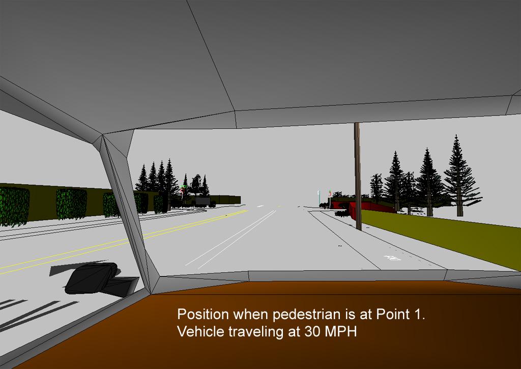
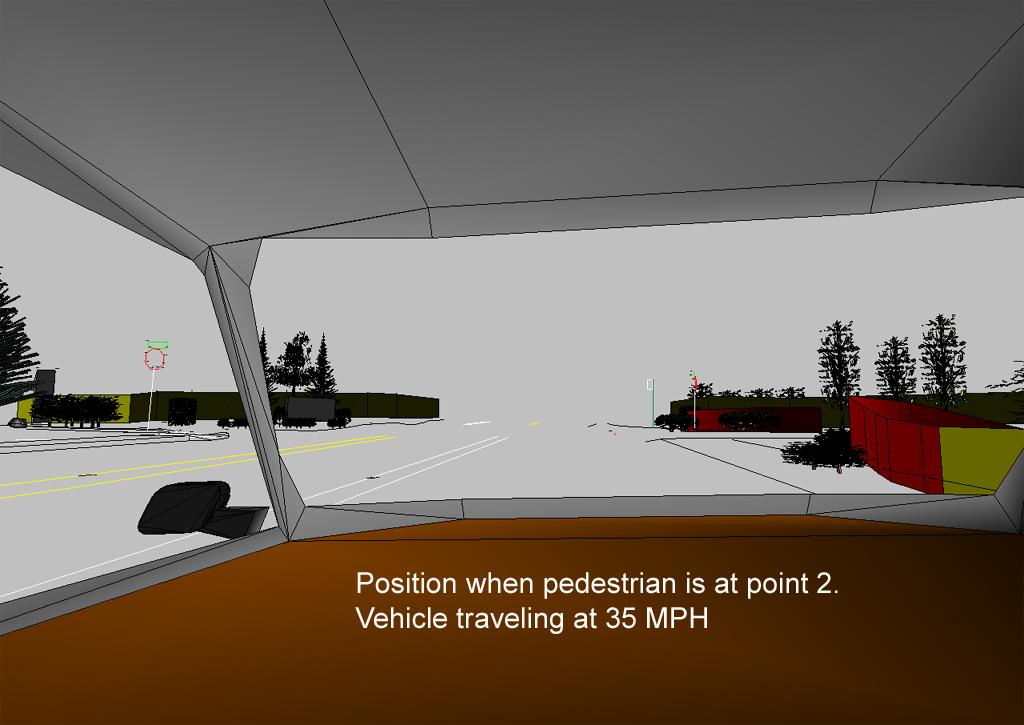
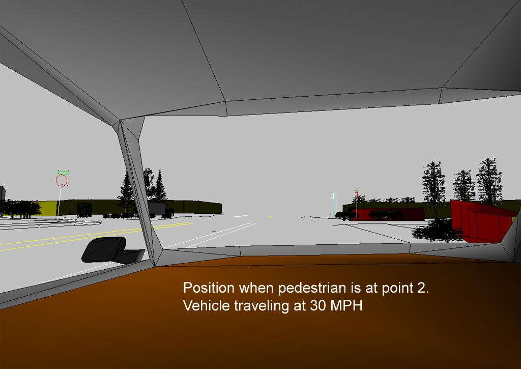
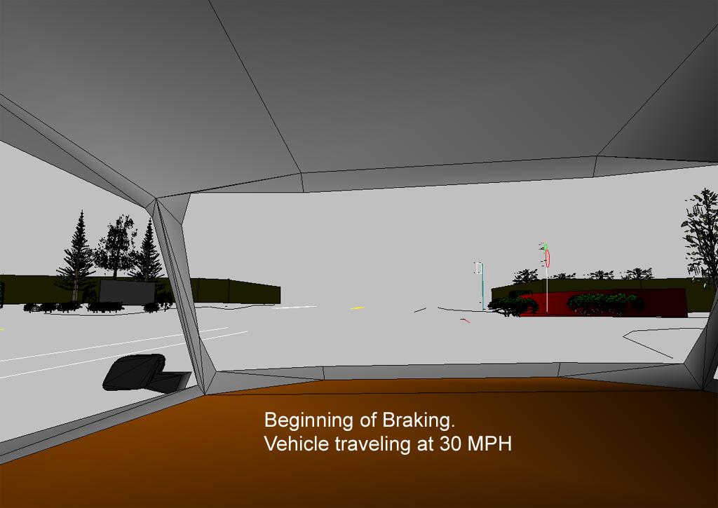
26 The pedestrian was struck and killed after stepping off this sidewalk and then running across the street in a north to northwest direction to catch a bus. The sidewalk corner was imaged for possible sightline obstruction for the pedestrian (and also for the driver). The 3D photogrammetric model from iwitness, upon importation into CAD, allows one to stand on the sidewalk at the crosswalk, or to sit in the drivers seat. iwitness was used to measure all entities including the crosswalk (curb step-off.) Looking East oncoming car westbound
27 A TIME & DISTANCE STUDY was performed using the information from witnesses at the scene, along with the measured police images, with post-site survey measuring / modeling using iwitness. iwitness measurements are now displayed in CAD - creating a 3D view of the scene as viewed from the drivers perspective. Time & Distance calculations were made from driving speeds of 30 and 35 mph at specific distances of the car in the road from the pedestrian running across the street.

28 Pedestrian Curb Step-off to cross street Looking West
29
30
31
32
33
34
35 What about accuracy of the photogrammetric measurements?
 revealed iwitness 3D object point uncertainty of.5 (1.2 cm) RMS. The measured 3D points are accurate (overall) to better than 1.5 - mapping a single photogrammetric network of 500 feet.")
36 Just how accurate is the iwitness 3D point data for this project? Internal accuracy estimates:.4 (1cm) RMS Check distances (tape and measuring standards, (i.e., stop signs, sidewalk widths, road lane widths etc.,) revealed iwitness 3D object point uncertainty of.5 (1.2 cm) RMS. The measured 3D points are accurate (overall) to better than mapping a single photogrammetric network of 500 feet.
37 Summary iwitness provides a 3D measurement tool for accident recording and reconstruction that is: Fast minimizing traffic disruption and road closures Comprehensive any feature of interest can be measured, at any time Accurate can measure to fractions of an inch within large-area accident scenes Reliable the inherent redundancy of multiple images makes iwitness a very reliable 3D measurement tool Flexible digital or film recording can occur in most conditions Easy to use needs only an amateur camera & the easy-to-use iwitness software Inexpensive total system cost can be as low as a few thousand dollars, or about 10-20% of the cost of a total station Widely use hundreds of users employ iwitness in various local, state and federal police and traffic agencies, as well as in other application domains such as engineering measurement and heritage recording Capable of providing a re-measurement or further measurement at any time after the fact from the archived images and it is noteworthy that iwitness was developed especially for accident reconstruction and 3D forensic measurement
Determining Crash Data Using Camera Matching Photogrammetric Technique
 SAE TECHNICAL PAPER SERIES 2001-01-3313 Determining Crash Data Using Camera Matching Photogrammetric Technique Stephen Fenton, William Neale, Nathan Rose and Christopher Hughes Knott Laboratory, Inc. Reprinted
PHOTOGRAMMETRY STEREOSCOPY FLIGHT PLANNING PHOTOGRAMMETRIC DEFINITIONS GROUND CONTROL INTRODUCTION
 PHOTOGRAMMETRY STEREOSCOPY FLIGHT PLANNING PHOTOGRAMMETRIC DEFINITIONS GROUND CONTROL INTRODUCTION Before aerial photography and photogrammetry became a reliable mapping tool, planimetric and topographic
APPLICATION OF PHOTOGRAMMETRY TO BRIDGE MONITORING
 APPLICATION OF PHOTOGRAMMETRY TO BRIDGE MONITORING Jónatas Valença, Eduardo Júlio, Helder Araújo ISR, University of Coimbra, Portugal jonatas@dec.uc.pt, ejulio@dec.uc.pt, helder@isr.uc.pt KEYWORDS: Photogrammetry;
A New Capability for Crash Site Documentation
 A New Capability for Crash Site Documentation By Major Adam Cybanski, Directorate of Flight Safety, Ottawa Major Adam Cybanski is the officer responsible for helicopter investigation (DFS 2-4) at the Canadian
Technical information about PhoToPlan
 Technical information about PhoToPlan The following pages shall give you a detailed overview of the possibilities using PhoToPlan. kubit GmbH Fiedlerstr. 36, 01307 Dresden, Germany Fon: +49 3 51/41 767
ECEN 4606, UNDERGRADUATE OPTICS LAB
 ECEN 4606, UNDERGRADUATE OPTICS LAB Lab 2: Imaging 1 the Telescope Original Version: Prof. McLeod SUMMARY: In this lab you will become familiar with the use of one or more lenses to create images of distant
APPENDIX C: Photography Guidelines
 APPENDIX C: Photography Guidelines The purpose of the photos is to convey to the readers of the report your recommendation for the property s eligibility or non-eligibility for the National Register. You
CRM 230 Module 2 Lecture Notes. Crime Scene Search
 CRM 230 Module 2 Lecture Notes Crime Scene Search Hello. This presentation will discuss sequential processing of a crime scene and the importance of identification and individualization of evidence. It
UltraCam Eagle Prime Aerial Sensor Calibration and Validation
 UltraCam Eagle Prime Aerial Sensor Calibration and Validation Michael Gruber, Marc Muick Vexcel Imaging GmbH Anzengrubergasse 8/4, 8010 Graz / Austria {michael.gruber, marc.muick}@vexcel-imaging.com Key
CSI: Rombalds Moor Photogrammetry Photography
 Photogrammetry Photography Photogrammetry Training 26 th March 10:00 Welcome Presentation image capture Practice 12:30 13:15 Lunch More practice 16:00 (ish) Finish or earlier What is photogrammetry 'photo'
Using PhotoModeler for 2D Template Digitizing Eos Systems Inc.
 Using PhotoModeler for 2D Template Digitizing 2017 Eos Systems Inc. Table of Contents The Problem... 3 Why use a photogrammetry package?... 3 Caveats and License to Use... 3 The Basic Premise... 3 The
Chapters 1 & 2. Definitions and applications Conceptual basis of photogrammetric processing
 Chapters 1 & 2 Chapter 1: Photogrammetry Definitions and applications Conceptual basis of photogrammetric processing Transition from two-dimensional imagery to three-dimensional information Automation
Crime Scene Diagramming: Back to Basics
 Crime Scene Diagramming: Back to Basics Kent E. Boots It is quite common in crime scene reconstruction for some type of analysis, e.g., trajectory, blood spatter, etc., to be based on measurements taken
FRAUNHOFER AND FRESNEL DIFFRACTION IN ONE DIMENSION
 FRAUNHOFER AND FRESNEL DIFFRACTION IN ONE DIMENSION Revised November 15, 2017 INTRODUCTION The simplest and most commonly described examples of diffraction and interference from two-dimensional apertures
Driver Education Classroom and In-Car Curriculum Unit 3 Space Management System
 Driver Education Classroom and In-Car Curriculum Unit 3 Space Management System Driver Education Classroom and In-Car Instruction Unit 3-2 Unit Introduction Unit 3 will introduce operator procedural and
4) Click on Load Point Cloud to load the.czp file from Scene. Open Intersection_Demo.czp
 Click on Load Point Cloud to load the.czp file from Scene. Open Intersection_Demo.czp") Intersection 2D Demo 1) Open the Crash Zone or Crime Zone diagram program. 2) Click on to open the CZ Point Cloud tool. 3) Click on 3D/Cloud Preferences. a) Set the Cloud File Units (Feet or Meters). b)
Intersection 2D Demo 1) Open the Crash Zone or Crime Zone diagram program. 2) Click on to open the CZ Point Cloud tool. 3) Click on 3D/Cloud Preferences. a) Set the Cloud File Units (Feet or Meters). b)
UAV PHOTOGRAMMETRY COMPARED TO TRADITIONAL RTK GPS SURVEYING
 UAV PHOTOGRAMMETRY COMPARED TO TRADITIONAL RTK GPS SURVEYING Brad C. Mathison and Amber Warlick March 20, 2016 Fearless Eye Inc. Kansas City, Missouri www.fearlesseye.com KEY WORDS: UAV, UAS, Accuracy
TECHNICAL INFORMATION Traffic Template Catalog No. TT1
 Copyright 2016 by SIRCHIE All Rights Reserved. TECHNICAL INFORMATION Traffic Template Catalog No. TT1 INTRODUCTION Your SIRCHIE Traffic Template is a versatile police tool designed to make even the most
Video 8: 2 Point Perspective
 Video 8: 2 Point Perspective Two point perspective is a drawing method using lines to create the illusion of space on a 2-Dimensional surface. Two point perspective is one of the six ways an artist can
HD aerial video for coastal zone ecological mapping
 HD aerial video for coastal zone ecological mapping Albert K. Chong University of Otago, Dunedin, New Zealand Phone: +64 3 479-7587 Fax: +64 3 479-7586 Email: albert.chong@surveying.otago.ac.nz Presented
6.A44 Computational Photography
 Add date: Friday 6.A44 Computational Photography Depth of Field Frédo Durand We allow for some tolerance What happens when we close the aperture by two stop? Aperture diameter is divided by two is doubled
Source: (January 4, 2010)
") Source: http://www.slrgear.com/reviews/showproduct.php/product/101/cat/12 (January 4, 2010) Name Nikon 105mm ƒ/2d AF DC Nikkor Image Circle 35mm Type Telephoto Prime Defocus Control Focal Length 105mm
Source: http://www.slrgear.com/reviews/showproduct.php/product/101/cat/12 (January 4, 2010) Name Nikon 105mm ƒ/2d AF DC Nikkor Image Circle 35mm Type Telephoto Prime Defocus Control Focal Length 105mm
ON THE CREATION OF PANORAMIC IMAGES FROM IMAGE SEQUENCES
 ON THE CREATION OF PANORAMIC IMAGES FROM IMAGE SEQUENCES Petteri PÖNTINEN Helsinki University of Technology, Institute of Photogrammetry and Remote Sensing, Finland petteri.pontinen@hut.fi KEY WORDS: Cocentricity,
ContextCapture Quick guide for photo acquisition
 ContextCapture Quick guide for photo acquisition ContextCapture is automatically turning photos into 3D models, meaning that the quality of the input dataset has a deep impact on the output 3D model which
8.EE. Development from y = mx to y = mx + b DRAFT EduTron Corporation. Draft for NYSED NTI Use Only
 8.EE EduTron Corporation Draft for NYSED NTI Use Only TEACHER S GUIDE 8.EE.6 DERIVING EQUATIONS FOR LINES WITH NON-ZERO Y-INTERCEPTS Development from y = mx to y = mx + b DRAFT 2012.11.29 Teacher s Guide:
Sample Copy. Not For Distribution.
 Photogrammetry, GIS & Remote Sensing Quick Reference Book i EDUCREATION PUBLISHING Shubham Vihar, Mangla, Bilaspur, Chhattisgarh - 495001 Website: www.educreation.in Copyright, 2017, S.S. Manugula, V.
AutoCAD Line Types If AutoCAD linetypes are disabled during configuration, Slick! will only plot/print straight lines!
 Print / Plot To print the contents of the graphics window, select File? Print/Plot from the menu bar. Slick! can print or plot directly to the Windows printer or plotter. In this discussion, the term printing
Autofocus Problems The Camera Lens
 NEWHorenstein.04.Lens.32-55 3/11/05 11:53 AM Page 36 36 4 The Camera Lens Autofocus Problems Autofocus can be a powerful aid when it works, but frustrating when it doesn t. And there are some situations
Photogrammetric Measurement Error Associated with Lens Distortion
 Copyright 2011 SAE International 2011-01-0286 Photogrammetric Measurement Error Associated with Lens Distortion William T.C. Neale, David Hessel, Toby Terpstra Kineticorp, LLC ABSTRACT All camera lenses
5 THINGS YOU PROBABLY DIDN T KNOW ABOUT CAMERA SHUTTER SPEED
 Photzy 5 THINGS YOU PROBABLY DIDN T KNOW ABOUT CAMERA SHUTTER SPEED Quick Guide Written by Kent DuFault 5 THINGS YOU PROBABLY DIDN T KNOW ABOUT CAMERA SHUTTER SPEED // PHOTZY.COM 1 There are a few things
Nikon 24mm f/2.8d AF Nikkor (Tested)
") Nikon 24mm f/2.8d AF Nikkor (Tested) Name Nikon 24mm ƒ/2.8d AF Nikkor Image Circle 35mm Type Wide Prime Focal Length 24mm APS Equivalent 36mm Max Aperture ƒ/2.8 Min Aperture ƒ/22 Diaphragm Blades 7 Lens
Nikon 24mm f/2.8d AF Nikkor (Tested) Name Nikon 24mm ƒ/2.8d AF Nikkor Image Circle 35mm Type Wide Prime Focal Length 24mm APS Equivalent 36mm Max Aperture ƒ/2.8 Min Aperture ƒ/22 Diaphragm Blades 7 Lens
ESD 4.0 Quick Start Lessons
 ESD 4.0 Quick Start Lessons Overview The following lessons will teach you the skills needed to draw most traffic accident scenes. Using Easy Street Draw, follow the step-by-step instructions to create
Applying Automated Optical Inspection Ben Dawson, DALSA Coreco Inc., ipd Group (987)
") Applying Automated Optical Inspection Ben Dawson, DALSA Coreco Inc., ipd Group bdawson@goipd.com (987) 670-2050 Introduction Automated Optical Inspection (AOI) uses lighting, cameras, and vision computers
Applying Automated Optical Inspection Ben Dawson, DALSA Coreco Inc., ipd Group bdawson@goipd.com (987) 670-2050 Introduction Automated Optical Inspection (AOI) uses lighting, cameras, and vision computers
THE SCHOOL BUS. Figure 1
 THE SCHOOL BUS Federal Motor Vehicle Safety Standards (FMVSS) 571.111 Standard 111 provides the requirements for rear view mirror systems for road vehicles, including the school bus in the US. The Standards
Image Formation. Dr. Gerhard Roth. COMP 4102A Winter 2015 Version 3
 Image Formation Dr. Gerhard Roth COMP 4102A Winter 2015 Version 3 1 Image Formation Two type of images Intensity image encodes light intensities (passive sensor) Range (depth) image encodes shape and distance
The Crash Zone - The Crime Zone User s Manual
 The Crash Zone - The Crime Zone User s Manual Copyright 2008 The CAD Zone, Inc. - Beaverton, OR All Rights Reserved Contents Table of Contents 2 Installing and Evaluating Your Software 4 Evaluating the
Guide to Basic Composition
 Guide to Basic Composition Begins with learning some basic principles. This is the foundation on which experience is built and only experience can perfect camera composition skills. While learning to operate
Zoom-Dependent Camera Calibration in Digital Close-Range Photogrammetry
 Zoom-Dependent Camera Calibration in Digital Close-Range Photogrammetry C.S. Fraser and S. Al-Ajlouni Abstract One of the well-known constraints applying to the adoption of consumer-grade digital cameras
RECENT DEVELOPMENTS IN EMERGENCY VEHICLE TRAFFIC SIGNAL PREEMPTION AND COLLISION AVOIDANCE TECHNOLOGIES. Purdue Road School 2017 Dave Gross
 RECENT DEVELOPMENTS IN EMERGENCY VEHICLE TRAFFIC SIGNAL PREEMPTION AND COLLISION AVOIDANCE TECHNOLOGIES Purdue Road School 2017 Dave Gross Preemption Technology Platform types Acoustic Optical GPS Radio
Kent Messamore 3/12/2010
 Photo Composition Kent Messamore 3/12/2010 Composition Choosing a Subject Quality of Light Framing the Image Depth of Field Backgrounds and Foregrounds Viewpoint Leading Lines Contrasts Patterns Negative
Point Calibration. July 3, 2012
 Point Calibration July 3, 2012 The purpose of the Point Calibration process is to generate a map of voltages (for galvos) or motor positions of the pointing device to the voltages or pixels of the reference
FoamWorks Introduction. David Mrozinski 848 W. Borton Road Essexville, Michigan 48732
 FoamWorks 4.0 Introduction Quick Start Registration Registration Menus Files Save a Cut Profile Load a Cut Profile Close Profile/G-code Restore Default Cut Profile Exit Setup Setup Parameters Generate
BOSTON EVERETT HORIZON WAY BROADWAY ALFORD ST BOW ST BOSTON CITY LINE EVERETT CITY LINE DEXTER ST MYSTIC ST COURTLAND ST LYNDE ST THORNDIKE ST
 BOSTON HORIZON WAY ALFORD ST BROADWAY BOSTON CITY LINE CITY LINE MANHOLE #101 (STA 5+00) BOW ST DEXTER ST ST LYNDE ST THORNDIKE ST COURTLAND ST RIVER PROP (TYP) ROBIN ST BETTY ST 50 500 1. BASELINE STATIONING
RRR Design & Modeling with the FDOT Civil 3D State Kit
 RRR Design & Modeling with the FDOT Civil 3D State Kit Mike Racca - CADD Applications Development Specialist Production Support Office CADD 605 Suwannee St - MS 40, Tallahassee, Florida 32399 Session Objectives:
PhotoModeler Quick Start Guide
 PhotoModeler Quick Start Guide Start Here First Eos Systems Inc. 6th Edition Jan 2014 Copyrights & Legal 2014 Eos Systems Inc. All rights reserved. No part of this publication can be reproduced, transmitted,
We will study all three methods, but first let's review a few basic points about units of measurement.
 WELCOME Many pay items are computed on the basis of area measurements, items such as base, surfacing, sidewalks, ditch pavement, slope pavement, and Performance turf. This chapter will describe methods
E X P E R I M E N T 12
 E X P E R I M E N T 12 Mirrors and Lenses Produced by the Physics Staff at Collin College Copyright Collin College Physics Department. All Rights Reserved. University Physics II, Exp 12: Mirrors and Lenses
Traversing the UNSW campus using
 GMAT 4010 - Thesis B UNSW School of Surveying and Spatial Information Systems Traversing the UNSW campus using Terrestrial Photogrammetry Author: Jarrod Braybon z3219882 j.braybon@student.unsw.edu.au Supervisor
Chapter 29/30. Wave Fronts and Rays. Refraction of Sound. Dispersion in a Prism. Index of Refraction. Refraction and Lenses
 Chapter 29/30 Refraction and Lenses Refraction Refraction the bending of waves as they pass from one medium into another. Caused by a change in the average speed of light. Analogy A car that drives off
Manufacturing Metrology Team
 The Team has a range of state-of-the-art equipment for the measurement of surface texture and form. We are happy to discuss potential measurement issues and collaborative research Manufacturing Metrology
Opto Engineering S.r.l.
 TUTORIAL #1 Telecentric Lenses: basic information and working principles On line dimensional control is one of the most challenging and difficult applications of vision systems. On the other hand, besides
CHAPTER 7 Total Station Surveying. CE 316 March 2012
 CHAPTER 7 Total Station Surveying CE 316 March 2012 249 7.1 Introduction Total station surveying - defined as the use of electronic survey equipment used to perform horizontal and vertical measurements
Operating Rausch ScanCam within POSM.
 Operating Rausch ScanCam within POSM. POSM (Pipeline Observation System Management) // posmsoftware.com // info@posmsoftware.com // 859-274-0041 RAUSCH USA // www.rauschusa.com // reusa@rauschusa.com //
Plan Preparation Checklist
 Appendix D Plan Preparation Checklist It is the responsibility of the Designer to complete and submit this checklist along with all required drawings for OUC (EFP) Review. All drawings submitted for OUC
Creating a 3D Assembly Drawing
 C h a p t e r 17 Creating a 3D Assembly Drawing In this chapter, you will learn the following to World Class standards: 1. Making your first 3D Assembly Drawing 2. The XREF command 3. Making and Saving
Module 7. Memory drawing and quick sketching. Lecture-1
 Module 7 Lecture-1 Memory drawing and quick sketching. Sketching from memory is a discipline that produces great compositions and designs. Design, after all, is a creative process that involves recollection
PHOTOGRAMMETRIC RESECTION DIFFERENCES BASED ON LABORATORY vs. OPERATIONAL CALIBRATIONS
 PHOTOGRAMMETRIC RESECTION DIFFERENCES BASED ON LABORATORY vs. OPERATIONAL CALIBRATIONS Dean C. MERCHANT Topo Photo Inc. Columbus, Ohio USA merchant.2@osu.edu KEY WORDS: Photogrammetry, Calibration, GPS,
PHOTOGRAMMETRIC ADVANCED DETECTION SOLUTION INCIDENT DETECTION IN TUNNELS
 - 102 - PHOTOGRAMMETRIC ADVANCED DETECTION SOLUTION INCIDENT DETECTION IN TUNNELS de Kok P., Zenz T., Markus J. Siemens Building Technologies Austria ABSTRACT Use of photogrammetric methods and image analysis
PERFORMANCE EVALUATIONS OF MACRO LENSES FOR DIGITAL DOCUMENTATION OF SMALL OBJECTS
 PERFORMANCE EVALUATIONS OF MACRO LENSES FOR DIGITAL DOCUMENTATION OF SMALL OBJECTS ideharu Yanagi a, Yuichi onma b, irofumi Chikatsu b a Spatial Information Technology Division, Japan Association of Surveyors,
Image Formation. Dr. Gerhard Roth. COMP 4102A Winter 2014 Version 1
 Image Formation Dr. Gerhard Roth COMP 4102A Winter 2014 Version 1 Image Formation Two type of images Intensity image encodes light intensities (passive sensor) Range (depth) image encodes shape and distance
TAKING PICTURES. 1. Be sure your picture has a point of interest.
 TAKING PICTURES 1. Be sure your picture has a point of interest. Each picture should have one principal idea or point of interest. That is, the eye of someone looking at the picture should, at a glance,
Extending the Dynamic Range of Film
 Written by Jonathan Sachs Copyright 1999-2003 Digital Light & Color Introduction Limited dynamic range is a common problem, especially with today s fine-grained slide films. When photographing contrasty
Getting Started. with Easy Blue Print
 Getting Started with Easy Blue Print User Interface Overview Easy Blue Print is a simple drawing program that will allow you to create professional-looking 2D floor plan drawings. This guide covers the
For customers in USA This device complies with Part 15 of the FCC rules. Operation is subject to the following two conditions:
 User manual For customers in North and South America For customers in USA This device complies with Part 15 of the FCC rules. Operation is subject to the following two conditions: (1) This device may not
Introduction. Note. This is about what happens on the streets.
 Page : 1 Note If there are people who have any commitment with certain photos, and do not wish the photo s on this book please let it now to XinXii, so they could contact me and I make sure the photos
SCIENCE & TECHNOLOGY
 Pertanika J. Sci. & Technol. 21 (2): 387-396 (2013) SCIENCE & TECHNOLOGY Journal homepage: http://www.pertanika.upm.edu.my/ Production of Orthophoto and Volume Determination Using Low-Cost Digital Cameras
Lesson 4: Photogrammetry
 This work by the National Information Security and Geospatial Technologies Consortium (NISGTC), and except where otherwise Development was funded by the Department of Labor (DOL) Trade Adjustment Assistance
So far, I have discussed setting up the camera for
 Chapter 3: The Shooting Modes So far, I have discussed setting up the camera for quick shots, relying on features such as Auto mode for taking pictures with settings controlled mostly by the camera s automation.
Photography Composition Basics
 Photography Composition Basics The Rule of Thirds The Rule of Thirds The rule of thirds involves mentally dividing up your image using 2 horizontal lines and 2 vertical lines, as shown below. You then
Adding Content and Adjusting Layers
 56 The Official Photodex Guide to ProShow Figure 3.10 Slide 3 uses reversed duplicates of one picture on two separate layers to create mirrored sets of frames and candles. (Notice that the Window Display
CHEM 4930 Forensic Science Analysis. Lecture 4
 CHEM 4930 Forensic Science Analysis Lecture 4 Documentation Documentation The most important activity that is performed at a crime scene Types of documentation Notes Photographs Sketches Taking Photographs
Relative Coordinates
 AutoCAD Essentials Most drawings are created using relative coordinates. This means that the next point is set from the last point drawn. The last point drawn is stored as temporary 0,0". AutoCAD uses
Following are the geometrical elements of the aerial photographs:
 Geometrical elements/characteristics of aerial photograph: An aerial photograph is a central or perspective projection, where the bundles of perspective rays meet at a point of origin called perspective
EXPERIMENT ON PARAMETER SELECTION OF IMAGE DISTORTION MODEL
 IARS Volume XXXVI, art 5, Dresden 5-7 September 006 EXERIMENT ON ARAMETER SELECTION OF IMAGE DISTORTION MODEL Ryuji Matsuoa*, Noboru Sudo, Hideyo Yootsua, Mitsuo Sone Toai University Research & Information
Structured-Light Based Acquisition (Part 1)
") Structured-Light Based Acquisition (Part 1) CS635 Spring 2017 Daniel G. Aliaga Department of Computer Science Purdue University Passive vs. Active Acquisition Passive + Just take pictures + Does not intrude
Structured-Light Based Acquisition (Part 1) CS635 Spring 2017 Daniel G. Aliaga Department of Computer Science Purdue University Passive vs. Active Acquisition Passive + Just take pictures + Does not intrude
DatuGram 2D. User Guide. Version 2.0 August Datumate Geomatics Expert Systems
 DatuGram 2D User Guide Version 2.0 August 2013 Datumate Geomatics Expert Systems Using DatuGram, land surveying is made easier, faster and with excellent geodetic accuracy. For more information please
RESULTS OF 3D PHOTOGRAMMETRY ON THE CMS BARREL YOKE
 RESULTS OF 3D PHOTOGRAMMETRY ON THE CMS BARREL YOKE R. GOUDARD, C. HUMBERTCLAUDE *1, K. NUMMIARO CERN, European Laboratory for Particle Physics, Geneva, Switzerland 1. INTRODUCTION Compact Muon Solenoid
Use of Photogrammetry for Sensor Location and Orientation
 Use of Photogrammetry for Sensor Location and Orientation Michael J. Dillon and Richard W. Bono, The Modal Shop, Inc., Cincinnati, Ohio David L. Brown, University of Cincinnati, Cincinnati, Ohio In this
Stalker Speed Sensor II Traffic Statistics Sensor Manual rev A
 Stalker Speed Sensor II Traffic Statistics Sensor Manual 011-0132-00 rev A Applied Concepts, Inc. 2609 Technology Drive Plano, Texas 75074 972-398-3780 ii Applied Concepts TRAFFIC STATISTICS SPEED SENSOR
Photography. Taking better photos
 Photography Taking better photos Composition Composition is the arrangement of the visual elements of the photograph, such as Geometric elements, such as lines, shapes, and curves Contrasts of tone, color,
Lighting Techniques 18 The Color of Light 21 SAMPLE
 Advanced Evidence Photography Contents Table of Contents General Photographic Principles. 2 Camera Operation 2 Selecting a Lens 2 Focusing 3 Depth of Field 4 Controlling Exposure 6 Reciprocity 7 ISO Speed
CAMERA BASICS. Stops of light
 CAMERA BASICS Stops of light A stop of light isn t a quantifiable measurement it s a relative measurement. A stop of light is defined as a doubling or halving of any quantity of light. The word stop is
TECHNICAL DOCUMENTATION
 TECHNICAL DOCUMENTATION NEED HELP? Call us on +44 (0) 121 231 3215 TABLE OF CONTENTS Document Control and Authority...3 Introduction...4 Camera Image Creation Pipeline...5 Photo Metadata...6 Sensor Identification
Be aware that there is no universal notation for the various quantities.
 Fourier Optics v2.4 Ray tracing is limited in its ability to describe optics because it ignores the wave properties of light. Diffraction is needed to explain image spatial resolution and contrast and
Vic-2D Manual. Rommel Cintrón University of Puerto Rico, Mayagüez. NEES at CU Boulder CU-NEES-08-07
 CU-NEES-08-07 NEES at CU Boulder 01000110 01001000 01010100 The George E Brown, Jr. Network for Earthquake Engineering Simulation Vic-2D Manual By Rommel Cintrón University of Puerto Rico, Mayagüez September
Below are the desired outcomes and usage competencies based on the completion of Project 4.
 Engineering Design with SolidWorks Project 4 Below are the desired outcomes and usage competencies based on the completion of Project 4. Project Desired Outcomes: An understanding of the customer s requirements
Which equipment is necessary? How is the panorama created?
 Congratulations! By purchasing your Panorama-VR-System you have acquired a tool, which enables you - together with a digital or analog camera, a tripod and a personal computer - to generate high quality
Template Drawings. Template Drawings. AutoCAD Essentials
 AutoCAD Essentials Starting a new drawing using any CAD software requires a series of steps. Measurement units, sheet size, layer designations, text fonts and text sizes plus many more items must be set.
Models Horizons & Vanishing Points Multiple Horizons & Vanishing Points Values & Vanishing Points Tricks
 2P erspectives Models Horizons & Vanishing Points Multiple Horizons & Vanishing Points Values & Vanishing Points Tricks Disne y Enterp rises, In c. Disney Enterprises, Inc. 2T his chapter... covers the
Guidance on Using Scanning Software: Part 5. Epson Scan
 Guidance on Using Scanning Software: Part 5. Epson Scan Version of 4/29/2012 Epson Scan comes with Epson scanners and has simple manual adjustments, but requires vigilance to control the default settings
ROTATING SYSTEM T-12, T-20, T-50, T- 150 USER MANUAL
 ROTATING SYSTEM T-12, T-20, T-50, T- 150 USER MANUAL v. 1.11 released 12.02.2016 Table of contents Introduction to the Rotating System device 3 Device components 4 Technical characteristics 4 Compatibility
I-I. S/Scientific Report No. I. Duane C. Brown. C-!3 P.O0. Box 1226 Melbourne, Florida
 S AFCRL.-63-481 LOCATION AND DETERMINATION OF THE LOCATION OF THE ENTRANCE PUPIL -0 (CENTER OF PROJECTION) I- ~OF PC-1000 CAMERA IN OBJECT SPACE S Ronald G. Davis Duane C. Brown - L INSTRUMENT CORPORATION
To start there are three key properties that you need to understand: ISO (sensitivity)
") Some Photo Fundamentals Photography is at once relatively simple and technically confusing at the same time. The camera is basically a black box with a hole in its side camera comes from camera obscura,
Some Photo Fundamentals Photography is at once relatively simple and technically confusing at the same time. The camera is basically a black box with a hole in its side camera comes from camera obscura,
Room 2D/3D Diagram Demo
 Room 2D/3D Diagram Demo PART 1) Basic Room Layout (2D) 1) Open the Crash Zone or Crime Zone diagram program. 2) Click on to open the CZ Point Cloud tool. 3) Click on 3D/Cloud Preferences. a) Set the Cloud
INVESTIGATION OF PHOTOTRIANGULATION ACCURACY WITH USING OF VARIOUS TECHNIQUES LABORATORY AND FIELD CALIBRATION
 INVESTIGATION OF PHOTOTRIANGULATION ACCURACY WITH USING OF VARIOUS TECHNIQUES LABORATORY AND FIELD CALIBRATION A. G. Chibunichev 1, V. M. Kurkov 1, A. V. Smirnov 1, A. V. Govorov 1, V. A. Mikhalin 2 *
One Point Perspective Drawing/Painting
 One Point Perspective Drawing/Painting Grade: 4 Medium: Drawing and Painting Learning Objective: Students will use one point perspective to create a piece of art that has a 3D appearance. Authors: Heather
To apply proposed roadway data (vertical alignments, cross section template data, cut/fill slopes, etc.)
") That CAD Girl J ennifer dib ona Website: www.thatcadgirl.com Email: thatcadgirl@aol.com Phone: (919) 417-8351 Fax: (919) 573-0351 Roadway Design Extracting Existing Ground Cross Sections This document
That CAD Girl J ennifer dib ona Website: www.thatcadgirl.com Email: thatcadgirl@aol.com Phone: (919) 417-8351 Fax: (919) 573-0351 Roadway Design Extracting Existing Ground Cross Sections This document
RESEARCH ON LOW ALTITUDE IMAGE ACQUISITION SYSTEM
 RESEARCH ON LOW ALTITUDE IMAGE ACQUISITION SYSTEM 1, Hongxia Cui, Zongjian Lin, Jinsong Zhang 3,* 1 Department of Information Science and Engineering, University of Bohai, Jinzhou, Liaoning Province,11,
DICOM Correction Proposal
 Tracking Information - Administration Use Only DICOM Correction Proposal Correction Proposal Number Status CP-1713 Letter Ballot Date of Last Update 2018/01/23 Person Assigned Submitter Name David Clunie
User Manual for HoloStudio M4 2.5 with HoloMonitor M4. Phase Holographic Imaging
 User Manual for HoloStudio M4 2.5 with HoloMonitor M4 Phase Holographic Imaging 1 2 HoloStudio M4 2.5 Software instruction manual 2013 Phase Holographic Imaging AB 3 Contact us: Phase Holographic Imaging