Safety Instructions for Parents and Children
|
|
|
- Katherine Shields
- 5 years ago
- Views:
Transcription
1

2 Safety Instructions for Parents and Children Attention! Please keep away from children under 3 years. Danger of suffocation by swallowing small parts. Risk of injury due to sharp tips and edges of individual components. We reserve the right to make technical changes. Please note: Only suitable for children over 8 years. Use under the supervision of adults recommended. Please read the instructions before use, follow them and keep them at hand for reference. Please keep the packaging. Battery: The kit requires a 9 V battery, which is not included in the package due to limited storability. A short-circuit of the battery must be avoided, because it can cause overheating of the cables and an explosion of the battery. After use, the battery clip must be removed of the battery. Non-rechargeable batteries must not be charged. There is a risk of explosion. Deformations of the batteries must be avoided. Used batteries must be disposed of according to environmental regulations. Please note: The LEDs, sensors and transistors must be inserted with the correct polarity for the circuits to work. The two transistors have a different designation and must not be confused. The motors must be connected correctly.


3 General Information All circuits presented in this manual have been developed, checked and tested with the utmost possible care. Nevertheless, mistakes cannot be completely excluded. The author is liable in cases of intent or gross negligence in accordance with the statutory provisions. For the rest, the author shall only be liable in accordance with the Product Liability Act for injury to life, body or health or for culpable breach of essential contractual obligations. The claim for damages for the violation of essential contractual obligations is limited to the contract-typical, foreseeable damage, unless there is a case of mandatory liability according to the Product Liability Act. The product has been manufactured in accordance with the applicable European directives and therefore bears the CE mark. The intended use is described in this manual. In the event of any other use or modification of the product, you are the only responsible for compliance with the applicable rules. Therefore, assemble the circuits exactly as described in the instructions. The crossed-out dustbin symbol means that this product must be recycled separately from household waste as electrical and electronic waste. Your local authority will tell you where to find the nearest free collection point.


4 Introduction We are pleased you have chosen this versatile robot assembly kit. varikabi offers you an exciting and playful approach to electronics. You will certainly have fun and variety with varikabi for a long time. Varikabi's "muscles" are two motors, his "brain cells" two transistors. The simple control circuits are placed on a small breadboard and are therefore easily modifiable. With the help of a clever combination of three brightness sensors varikabi perceives the smallest contrasts in its environment and reacts to them in many different ways. Thanks to a selector switch and by aligning and switching the sensors, you'll explore twelve different functions and amazing behaviors. varikabi can do a lot: - Overcome obstacle courses - Follow dark or light lines - Track or move objects - Search, track or circle light - Trace or circle shadows - Circle on light or dark areas
5 Content 1) Assembly varikabi is available in the seven colors red, blue, green, neon green, yellow, pink and black. Regardless of the color variant, there are seven different animal models to choose from. Numerous illustrations show you step by step how to assemble them. S. 9 varikabi as a Dog S. 17 varikabi as a Sea Lion S. 23 varikabi as a Frog S. 29 varikabi as a Bird S. 35 varikabi as a Giraffe S. 43 varikabi as a Mouse S. 51 varikabi as a Beetle S. 60 varikabi - Fischertechnik 2) Functions The experimentation manual explains the twelve functions of varikabi. It will show you how to build the appropriate circuits, connect the motors and set the three sensors. Finally, find a fault diagnosis in case something does not work as expected. 3) Operating Principle You will learn how the different control circuits and components of the kit work. You will learn varikabis behaviors and understand how they are caused. This part of the manual is still under construction and will be updated continuously.
6 1) Assembly What you need 9 V block battery or 9 V battery pliers and side cutters black duct tape (for varikabi FT) about one hour time


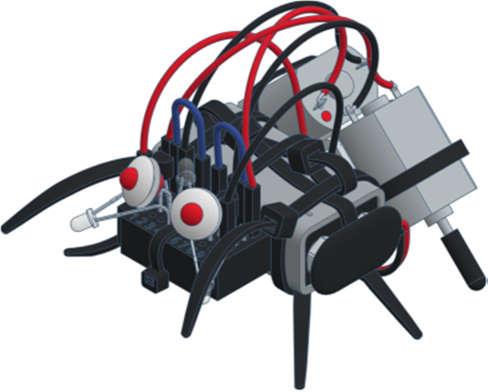

7 The seven varikabi models
8 The components


9 varikabi as a Dog
10 1)
11 2)
12 3)
13 4)
14 5)
15 6)
16 7)


17 varikabi as a Sea Lion
18 1)
19 2)
20 3)
21 4)
22 5)
23 varikabi as a Frog
24 1)
25 2)
26 3)
27 4)
28 5)


29 varikabi as a Bird
30 1)
31 2)
32 3)
33 4)
34 5)


35 varikabi as a Giraffe
36 1)
37 2)
38 3)
39 4)
40 5)
41 6)
42 7)


43 varikabi as a Mouse
44 1)
45 2)
46 3)
47 4)
48 5)
49 6)
50 7)


51 varikabi as a Beetle
52 1)
53 2)
54 3)
55 4)
56 5)
57 6)
58 7)
59 8)
60 varikabi - Fischertechnik
61 The components
62 1)
63 2)
64 3)
65 4)


66 2) Circuits and Functions The different circuit variants allow varikabi twelve functions. The circuits and features of the functions are described below in detail. varikabi stands still varikabi drives slowly varikabi drives fast
67 Notes on Lighting Unlike many other robots, varikabi does not need to emit infrared light to detect lines or objects in front of it. This simplifies the circuit and reduces power consumption. Since varikabi reacts on brightness differences in the environment, it is essential to use a suitable light source. Note: The light of LED lamps or fluorescent lamps has a low red component and is not well perceptible for varikabi's sensors. When using these light sources, a sufficiently strong illumination must therefore be provided. To avoid that varikabi's sensors are not blinded by the light source, attention must also be paid to a suitable position in relation to lamps or windows. Note: Most functions can be performed best under a sufficiently distant lamp or under a window on the floor. In the case of lateral light incidence varikabi would follow this light or its own shadow instead of driving to the desired target. If varikabi is supposed to follow or avoid a structure on the ground, make sure that the ground does not reflect light.
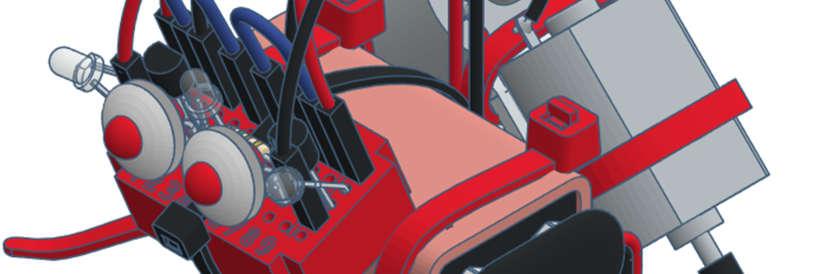
68 Breadboard With a breadboard simple electronic circuits can be set up and changed very quickly. Our small breadboard has eleven rows of five pins each connected internally. The outer two rows are used for the power supply (+/-). The rest are labeled with the numbers 1 to 9. The fifth row in the middle is concealed at varikabi with the black cable tie and is not needed. Resistor The resistor limits the current of the two LEDs. The colored rings indicate the value of the ohmic resistance, which in our case is 150 Ω (ohms). Bend the connecting wires of the resistor at a distance of 10 mm and shorten them to a length of approx. 15 mm. Then put the resistor in the center of the breadboard.


69 Transistors Since varikabi's drive motors require a much higher current than the sensors can supply, amplifiers are needed. A transistor is a simple three-terminal electronic amplifier. To make sure that the gain is sufficiently high, so-called Darlington transistors are used, which already contain two series-connected transistors. The right and left motors require equivalent transistors, a so-called PNP and an NPN transistor. They can be distinguished by their imprint BC516 (PNP) or BC517 (NPN). Bend the outer two legs slightly apart so that the transistors fit well into the breadboard. Then insert them into the breadboard according to the illustration on the left and right of the resistor. Caution: The two transistors BC516 and BC517 must not be mixed-up and must be inserted turned differently.
 can be imagined essentially as a variable resistor whose resistance decreases as the brightness increases.")
70 Sensors varikabi compares the brightness at its three sensors. Depending on how the so-called phototransistors are aligned, varikabi perceives impressions of the ground, in front or above itself. A phototransistor (FT) can be imagined essentially as a variable resistor whose resistance decreases as the brightness increases. However, you must pay attention to the correct polarity of the phototransistor. The sensors are connected to the breadboard in all 12 circuits in the rows +, 4, 6 and -. Therefore, bend the connections slightly apart according to the illustration. The following pages describe how to install the three sensors for each function. Select a desired function and align the sensors accordingly. Caution: The phototransistors must be installed correctly polarized. The + side has a shorter leg and a flattening on the protruding collar of the case.
71 1) Following Dark Lines Searches for a dark line (e.g. black tape) Drives along the line Accelerates on straight stretches and brakes in curves Circuit: Shadow Follower / Acceleration Mode With the distance between the outer two sensors you can adjust the accuracy with which varikabi is supposed to drive on the line. Ideally, they are a little off the line. If they are too close to the line, varikabi will permanently adjust the direction and drive serpentines. In addition, it will not be able to activate its turbo, because for this more light must fall on the outer sensors than on the one in the center.
72 2) Following Light Lines Drives along a bright line (e.g. white tape on a dark background) Stops at the end of the line Circuit: Light Follower / Braking Mode If you do not have white adhesive tape, you can place white sheets of paper on a dark floor, for example. With the distance between the outer two sensors you can adjust the accuracy with which varikabi is supposed to drive on the line. To make varikabi stop at the end of a line (on a dark background), direct the center sensor further down than the two lateral sensors.

73 3) Tracking Light Traces a light on the ground or a lamp in front of him Stops in front of the light Stops when a shadow appears over him Circuit: Light Follower / Braking Mode The ambient light should not be too strong for this function, so that the contrast is strong enough. Align the side sensors in parallel or just slightly to the side so they can simultaneously keep a frontal light in sight. The more light hits the outer and the less the center sensor, the sooner varikabi will come to a standstill. This ratio can also be adjusted with the inclination of the center sensor.

74 4) Tracking Objects Moves towards dark objects in front of him Keeps distance and stops in front of them or tracks moving objects Circuit: Shadow Follower / Braking Mode Adjust the distance of the lateral sensors to the size of the object to be tracked. The further forward they are directed, the more exactly varikabi will follow the object. However, if they are both directed to the object, varikabi will not be able to stop in front of it. Use the tilt angle of the center sensor to adjust the distance to the object being tracked. The more you point it down, the closer varikabi will approach the object.
75 5) Pushing Objects Stands still when no dark object is in sight Starts moving when an object is in front and follows it pushes small things forward Circuit: Shadow Follower / Braking Mode Adjust the distance of the lateral sensors to the size of the object to be tracked. Both sensors should have the object in view at the same time. Adjust the angle of inclination of the middle sensor so that it is only slightly over the object. If the middle sensor points too steeply upwards, varikabi remains constantly in motion and can only be stopped by a shadow from above.


76 6) Avoiding Obstacles Stops in case of dark obstacles, navigates between them and then accelerates again Overcomes an obstacle course Circuit: Light Follower/ Acceleration Mode In order for varikabi to reliably avoid obstacles, these must be darker than the ground. Align the lateral sensors about 45 to the side and slightly to the ground. The further the sensors are directed downwards, the closer varikabi will approach obstacles before swerving. Adjust the tilt angle of the center sensor in the way that it is only slightly directed above the obstacles so that varikabi will be able to accelerate on free track.
77 7) Avoiding Dark Stays on a bright surface (e.g. illuminated table in the dark) Avoids dark obstacles Accelerates and escapes shadows appearing over it Circuit: Light Follower/ Acceleration Mode The bright area can be e.g. your room floor or a clear table illuminated from above. You can also place white sheets of paper on a dark background. Avoid lateral light incidence from windows. For varikabi to recognize the edge of the table well, the optimum angle of inclination of the two lateral sensors must be found. Caution: If you hold your hand above varikabi, it will only drive straight ahead without paying attention to its surrounding.
78 8) Avoiding Light Stands still on a light surface Drives steadily on a dark ground Turns away from light or stops in front of it Circuit: Shadow Follower / Braking Mode For the dark background, for example, you can cut black paper and place it on a light floor. The surface should be round and have a diameter of at least 30 cm. Adjust the inclination of the two lateral sensors in the way that varikabi will turn at the edge in time. Adjust the tilt angle of the middle sensor in the way that varikabi will always keep moving on the dark surface but stops on a light surface.

79 9) Following Shadows Avoids light and seeks shade Drives towards a shadow Stops in the shadow Tracks the shadow as it moves Circuit: Shadow Follower / Braking Mode Choose a place outdoor or underneath a light source, which is placed at least one meter high. Your hand is the best shadow. However, be careful not to wear clothes with dark sleeves, otherwise varikabi would prefer to follow the shadow of your arm. When you hold your hand over varikabi, it stops. Then slowly move your hand forwards or sideways so that varikabi can follow it.
80 10) Search Light Searches for a light above him and drives towards it Stops under the light Turns away of shadow and drives back into the light Circuit: Light Follower / Braking Mode For this experiment you need a dark room and a lamp about 30 to 100 cm above varikabi. Ideally, you can also move the lamp. However, a flashlight is not very suitable because of its focus. The more you direct the center sensor upwards, the further varikabi will move towards the center of the lit area before it stops. If you hold your hand between varikabi and the lamp, varikabi will try to return into the light.

81 11) Circling Around Light Looks for a light and drives fast towards it Then below the light it moves on slowly in circles Accelerates when shadow is above Circuit: Light Follower/ Acceleration Mode For this experiment you need a dark environment and a lamp about 30 to 100 cm above varikabi. A flashlight is not suitable because of its strong focus. If you place varikabi on the ground in some distance from the lamp, it will quickly approach the light. Below the lamp, it will slow down and keep turning in order not to move away from the lamp. With the inclination of the sensors you choose at which distance varikabi will make the turn.

82 12) Circling Around Shadow Turns away from light Accelerates when shadow is above Tries to stay in the shade and turns again and again Circuit: Shadow Follower / Acceleration Mode Choose a place outdoors, but not in the sun, or a room with uniform ceiling lighting. If you hold your hand or a larger object over varikabi, it will accelerate briefly and then turn steadily in order not to move out of the shadow. With the inclination of the sensors you set when varikabi will turn back each time. The two side sensors must always be directed slightly further backwards than the center sensor.
83 Cable Bridges The blue cables connect the sensors (FT 2, FT 3, FT 1 ) with the transistors (T 2,T 1 ). Depending on whether you connect them directly or crossed, varikabi will respond differently to a shadowing of the sensor FT 3 : FT 2 FT 3 FT 1 FT 2 FT 3 FT 1 T 2 T 1 T 2 T 1 The description of the 12 functions indicates whether you need to select the acceleration mode or the braking mode for each circuit. Plug the blue wires into rows 1, 4, 6 and 9 according to the illustration. Acceleration mode: Braking mode: varikabi gets faster varikabi slows down cables parallel cables crossed LEDs Unlike incandescent bulbs, LEDs must be properly polarized for them to light up. The shorter leg and the flattening on the housing mark the negative connection ( ) of an LED. Depending on the color you have two red, blue or green LEDs in your assembly kit. Depending on whether you have selected the braking mode or the acceleration mode, the LEDs must be bent and plugged-in in a different way. Finally, put the two white silicone sheaths on the LEDs. Note: varikabi's eye-leds will only light up at high speed or at standstill. This means always when the center sensor FT 3 is shaded.
84 Acceleration Mode Breaking Mode
85 Connection of the Motors varikabi moves with the help of two particularly slow and quiet DC motors. With the black rubber caps varikabi therefore requires neither a gear nor wheels. The speed of the motors is set by the level of the applied voltage. This voltage is controlled with the help of the transistors or the sensors respectively. Depending on which transistor (T 2, T 1 ) drives which one of the motors (M 2, M 1 ), the following behaviors arise: T 2 M 2 T 1 M 1 Shadow Follower T 2 M 2 T 1 M 1 Light Follower The following diagram shows how the cables are to be mounted in the rows Depending on the selected function, connect the motor cables as light or shadow follower. Light Follower: red cables are inside Shadow Follower: red cables are outside Note: By connecting the motors differently, you determine whether varikabi will be driving toward the dark or the light. The rotation direction of the motors depends on the polarity of the applied voltage. In order for varikabi's engines to spin forward, make sure that the red connections always cross and the black ones run parallel.
86 Light Follower Shadow Follower Caution: The red cables are crossed connected!
87 Power Supply In order to put varikabi into operation, the outer two rows of the breadboard now have to be supplied with power. To do this, lead the battery cable with the two plug-in connections from underneath through the gap between the bracket and the battery. Then insert the contacts of the battery cable to the positions on the breadboard indicated below. To avoid a short circuit between the plugs, leave them in the breadboard and use the clip connector on the battery to turn varikabi on and off. For a battery change, you can pull out the battery sideways.
88 Fault Diagnosis Problem Possible Reasons varikabi does not move at all. The left and right sensors are connected with the wrong polarity. A battery cable is not inserted correctly in the breadboard or the battery clip is not on the 9V battery. The battery is empty or defective. The rubber caps are too far on the motor shafts. Only one of the motors is running. The left or the right sensor is connected to the breadboard with the wrong polarity. A transistor is connected to the breadboard with the wrong polarity. A connection cable of the motor is not inserted correctly in the breadboard. A rubber cap is pushed too far on the motor shaft. A motor turns backwards. This motor is connected with the wrong polarity.
89 Problem varikabi only drives straight ahead. Possible Reasons The center sensor is connected incorrectly. The two LEDs do not light up. One or both LEDs are inserted with the wrong polarity. varikabi gets stuck on the ground. varikabi is not placed well or too uneven on the cable ties. The surface is too bumpy for varikabi. If none of these causes apply to your problem, check carefully that all components are installed as described in the construction plan. If you need help, please contact us with a detailed error description and preferably a photo of your robot: info@variobot.com
90 3) Operating Principle Depending on how the sensors are connected to the transistors and which motor is driven by which transistor, there are four basic control and circuit variants, which are shown on the following pages. Acceleration mode / Shadow Follower Acceleration mode / Light Follower Braking mode / Shadow Follower Braking mode / Light Follower All other features of the 12 functions are set by aligning the sensors. The obliquely drawn connections represent the blue cable bridges between the sensors and the transistors. The two LEDs are connected in series with the resistor and arranged between the transistors. In Acceleration mode they light up when the current flows through both transistors. In Braking mode they light up when the current flows through the motors in the other direction, as long as they stand still.
91 Circuit: Acceleration Mode/ Shadow Follower FT 2 T 2 M 2 L 2 FT 3 R +9 V Bat L 1 FT 1 T 1 M 1
92 Circuit: Acceleration Mode/ Light Follower FT 2 T 2 M 2 L 2 FT 3 R +9 V Bat L 1 FT 1 T 1 M 1
93 Circuit: Braking Mode/ Shadow Follower FT 2 T 2 M 2 L 2 FT 3 R +9 V Bat L 1 FT 1 T 1 M 1
94 Circuit: Braking Mode/ Light Follower FT 2 T 2 M 2 L 2 FT 3 R +9 V Bat L 1 FT 1 T 1 M 1
 between base and emitter, the transistor reduces the resistance between collector and emitter and - it is said - it switches through.")
95 The Transistors A transistor is a simple electronic amplifier with three connections: base (B), emitter (E) and collector (C). At a sufficiently high voltage of about U BE = 0.7 V (V = Volt) between base and emitter, the transistor reduces the resistance between collector and emitter and - it is said - it switches through. The collector current IC for ordinary transistors can be about 100 to 800 times larger than the base current I B. varikabi uses Darlington transistors with a very high current amplification of To supply the motor and LEDs with a current of 0.03 A (amps) = 30 ma (milliamperes), a base current of only 1 μa (microampere) is required: 30 ma / = ma = 1 µa A Darlington transistor consists of two transistors connected in series and requires about U BE =1.4 V instead of 0.7 V to switch through. To ensure that the motors react to the sensor signals in opposite directions, varikabi uses a complementary pair of transistors: one PNP transistor for T 1 (BC516) and one NPN transistor for T 2 (BC517) I B I B I C IC T 2 T 1
96 The adjacent figure shows a simple circuit with a battery, a motor and an NPN transistor. Underneath, the corresponding circuit is shown with a PNP transistor. The current flows in the direction of the black arrow from plus to minus in both cases. There are three different basic circuits with a transistor. varikabi uses the so-called collector circuit. It is called collector circuit because the collector (C) is connected to a constant voltage (battery). The red arrows symbolize the voltages. You can notice that the voltage at the motor U E is lower by the base-emitter voltage U BE than the base-voltage U B. U E = U B U BE = U B 1.4 V U B U BE U E Note: Because the voltage at the emitter (E) follows the voltage at the base (B) except for the difference of U BE, this circuit is also called emitter follower. With the control voltage U B and a very low current I B, the voltage U E and thus the speed of the motor can be controlled. U B U E U BE
97 The Sensors varikabi's phototransistors (FT) are similar in design to a transistor. The collector (C) is on the plus side and the emitter (E) is on the minus side. Instead of a basic connection, however, they have a light-sensitive area. The incidence of light determines the permeability between the collector and the emitter. The circuit diagram shows that the three phototransistors FT 1, FT 3 and FT 2 are all connected. They say they're in series. This series connection results in a socalled voltage divider, which divides the voltage of the 9 V battery depending on the illumination of the sensors. Examples: With exactly the same amount of light, the voltages at the sensors are three volts each, regardless of the brightness: U 2 = U 3 = U 1 = 3 V If, for example, the middle sensor FT 3 were illuminated four times brighter than FT 2 and FT 1, a voltage four times lower would drop at FT 3 and the supply voltage would be divided as follows: U 2 = 4 V, U 3 = 1 V, U 1 = 4 V Note: The two variable voltages between the three sensors control the speed of the two motors. FT 2 U 2 FT 3 U 3 FT 1 U 1
Build your own boombox
 Build your own boombox This amplifier kit with plug-in board and all necessary components is easy and quick to assemble, requires no soldering and is great fun. Listen to your favourite music with your
Basic Electronics Course Part 2
 Basic Electronics Course Part 2 Simple Projects using basic components Including Transistors & Pots Following are instructions to complete several electronic exercises Image 7. Components used in Part
DARK ACTIVATED COLOUR CHANGING NIGHT LIGHT KIT
 TEACHING RESOURCES SCHEMES OF WORK DEVELOPING A SPECIFICATION COMPONENT FACTSHEETS HOW TO SOLDER GUIDE CREATE SOOTHING LIGHTING EFFECTS WITH THIS DARK ACTIVATED COLOUR CHANGING NIGHT LIGHT KIT Version
EASY BUILD TIMER KIT TEACHING RESOURCES. Version 2.0 LEARN ABOUT SIMPLE TIMING CIRCUITS WITH THIS
 TEACHING RESOURCES SCHEMES OF WORK DEVELOPING A SPECIFICATION COMPONENT FACTSHEETS HOW TO SOLDER GUIDE LEARN ABOUT SIMPLE TIMING CIRCUITS WITH THIS EASY BUILD TIMER KIT Version 2.0 Index of Sheets TEACHING
DIODE / TRANSISTOR TESTER KIT
 DIODE / TRANSISTOR TESTER KIT MODEL DT-100K Assembly and Instruction Manual Elenco Electronics, Inc. Copyright 1988 Elenco Electronics, Inc. Revised 2002 REV-K 753110 DT-100 PARTS LIST If you are a student,
Manual Robot kit for experimentation. Mobile all-rounder Analog control Without programming For beginners and experts cm
 Manual Robot kit for experimentation Mobile all-rounder Analog control Without programming For beginners and experts AGE 14+ SIZE 1cm CONSTRUCTION2-4h PARTS 15 Introduction We are pleased that you have
Assembly Instructions: Kit #5
 Assembly Instructions: Kit #5 1. Insert the T-pin into one of the caps. 2. Insert the rotor core into the same cap as shown below. Apply some pressure to push the rotor core approximately 1/2" (10-12 mm)
Experiment Manual Electronics Learning Circuits Manual Cover.indd 1 3/29/11 2:19 PM
 Experiment Manual Instruction Manual Contents 4 Introduction 2 Electronics 3 The parts in your kit 6 Tips for assembling the circuits 9 Getting started with light-emitting diodes 0 Red light with green
DIODE / TRANSISTOR TESTER KIT
 DIODE / TRANSISTOR TESTER KIT MODEL DT-100K 99 Washington Street Melrose, MA 02176 Phone 781-665-1400 Toll Free 1-800-517-8431 Visit us at www.testequipmentdepot.com Assembly and Instruction Manual Elenco
STX Stair lighting controller.
 Stair lighting controller STX-1792 STX-1792 controller is used to control stairs lighting dynamically. The backlight is switched on with the subsequent steps, depending on the motion directions: ascending
General-Purpose Photoelectric Sensor
 General-Purpose Photoelectric Sensor Wide Selection of High Performance Small DC Sensors Offers Longer Sensing Distances Fast 0. msec response time for high-speed sensing Extended sensing distances up
LAB PROJECT 2. Lab Exercise
 LAB PROJECT 2 Objective Investigate photoresistors, infrared light emitting diodes (IRLED), phototransistors, and fiber optic cable. Type a semi-formal lab report as described in the lab manual. Use tables
IR add-on module circuit board assembly - Jeffrey La Favre January 27, 2015
 IR add-on module circuit board assembly - Jeffrey La Favre January 27, 2015 1 2 For the main circuits of the line following robot you soldered electronic components on a printed circuit board (PCB). The
RC Interface Controller Board Assembly and Operation
 RC Interface Controller Board Assembly and Operation Revision Date: January 17, 2006 SUPERDROIDROBOTS.COM RC Interface Controller Board Accurate content is of the utmost importance to the authors of this
Brick Challenge. Have fun doing the experiments!
 Brick Challenge Now you have the chance to get to know our bricks a little better. We have gathered information on each brick that you can use when doing the brick challenge: in case you don t know the
ELECTRONICS STARTER KIT
 ELECTRONICS STARTER KIT (MAP 474 - N02QQ) R These five small self-assembly circuits cover basic principles of electronics and can be adapted for numerous practical application. The five circuits include
Studuino Icon Programming Environment Guide
 Studuino Icon Programming Environment Guide Ver 0.9.6 4/17/2014 This manual introduces the Studuino Software environment. As the Studuino programming environment develops, these instructions may be edited
Line-Following Robot
 1 Line-Following Robot Printed Circuit Board Assembly Jeffrey La Favre October 5, 2014 After you have learned to solder, you are ready to start the assembly of your robot. The assembly will be divided
LABORATORY EXPERIMENT. Infrared Transmitter/Receiver
 LABORATORY EXPERIMENT Infrared Transmitter/Receiver (Note to Teaching Assistant: The week before this experiment is performed, place students into groups of two and assign each group a specific frequency
Top spin Nr /
 Top spin Nr. 1840 0000 / 1840 1000 Bedienungsanleitung 21-6680 28052014 / A Made in Germany Ideas for dental technology Top spin Nr. 1840 0000 / 1840 1000 Contents 1. Introduction...2 1.1 Symbols...2 2.
Warning: CHOKING HAZARD -Small Parts. Not for Children Under 9 yrs. Kit Recommended for Ages 12 and up.
 The Original Warning: CHOKING HAZARD -Small Parts. Not for Children Under 9 yrs. Kit Recommended for Ages 12 and up. Table of Contents Soldering.. 3 How the WASP Works.. 7 The Build...... 12 Troubleshooting......30
Light activated switch
 Build instructions, circuit explanation and example applications Issue 1.6 Product information: www.kitronik.co.uk/quicklinks/2112/ TEACHER Light activated switch Introduction About the project kit This
TV Remote. Discover Engineering. Youth Handouts
 Discover Engineering Youth Handouts Electronic Component Guide Component Symbol Notes Amplifier chip 1 8 2 7 3 6 4 5 Capacitor LED The amplifier chip (labeled LM 386) has 8 legs, or pins. Each pin connects
Operating mode. distance. 7 m Light ON Dark ON (selectable) 2 m [100 mm] (See note 1.) 100 mm (wide view)
![Operating mode. distance. 7 m Light ON Dark ON (selectable) 2 m [100 mm] (See note 1.) 100 mm (wide view)](/thumbs/83/88087955.jpg "Operating mode. distance. 7 m Light ON Dark ON (selectable) 2 m [100 mm] (See note 1.) 100 mm (wide view)") Built-in Amplifier Photoelectric Sensor E3S-A/B Revolutionary High-performance High-quality Sensor with Built-in Amplifier can be adjusted in seconds because the optical axis coincides with the mounting
Built-in Amplifier Photoelectric Sensor E3S-A/B Revolutionary High-performance High-quality Sensor with Built-in Amplifier can be adjusted in seconds because the optical axis coincides with the mounting
LAB 1 AN EXAMPLE MECHATRONIC SYSTEM: THE FURBY
 LAB 1 AN EXAMPLE MECHATRONIC SYSTEM: THE FURBY Objectives Preparation Tools To see the inner workings of a commercial mechatronic system and to construct a simple manual motor speed controller and current
Maximum Power Point (Student Handout) (The Principles of Optimizing Photovoltaic Cell Power Output)
 (The Principles of Optimizing Photovoltaic Cell Power Output)") Name(s): Maximum Power Point (Student Handout) (The Principles of Optimizing Photovoltaic Cell Power Output) Part 1: Investigating How a Photovoltaic (PV) System Works Take a look at the animation of a
Name(s): Maximum Power Point (Student Handout) (The Principles of Optimizing Photovoltaic Cell Power Output) Part 1: Investigating How a Photovoltaic (PV) System Works Take a look at the animation of a
Experimental Procedure
 1 of 17 9/11/2018, 1:24 PM https://www.sciencebuddies.org/science-fair-projects/project-ideas/robotics_p012/robotics/build-a-light-tracking-bristlebot (http://www.sciencebuddies.org/science-fairprojects/project-ideas/robotics_p012/robotics/build-a-light-tracking-bristlebot)
SERVICE MANUAL PARTS LIST MODEL: NH40
 SERVICE MANUAL & PARTS LIST MODEL: NH40 CONTENTS What to do when... 1-3 SERVICE ACCESS Face Cover... 4 Bed Cover... 5 Free-arm Cover... 6 Front Cover... 7 Rear Cover... 8 MECHANICAL ADJUSTMENT Presser
Repair manual. Fifth-wheel coupling JSK 38/50
 Repair manual Fifth-wheel coupling JSK 38/5 ZDE 199 3 12 E 6/212 1 Foreword Table of contents Page Fifth wheel couplings are connecting parts that must comply with very high safety requirements and must
An important note about your Charged Up Exploration Kit.
 ChargedUp Hands On Exploration Kit First An important note about your. DO NOT ASSUME that you will see something at the tournament because it was in this kit. This supplemental study material IS NOT part
Electronic Components
 Electronic Components Arduino Uno Arduino Uno is a microcontroller (a simple computer), it has no way to interact. Building circuits and interface is necessary. Battery Snap Battery Snap is used to connect
Bi-Directional DC Motor Speed Controller 5-32Vdc (3166v2)
") General Guidelines for Electronic Kits and Assembled Modules Thank you for choosing one of our products. Please take some time to carefully read the important information below concerning use of this product.
General Guidelines for Electronic Kits and Assembled Modules Thank you for choosing one of our products. Please take some time to carefully read the important information below concerning use of this product.
A Deluxe LED Blinky That You Can Build!
 Lux Spectralis A Deluxe LED Blinky That You Can Build! Assembly Instructions Contents Step 1: Parts check... 2 Step 2: Tool check... 3 Step 3: Install the computer chip... 3 Step 4: Install the resistors...
Fifth-wheel coupling JSK 38/50
 Repair manual Fifth-wheel coupling JSK 38/5 ZDE 199 3 12 E 6/25 1 LT SK38C-3 English RevA Foreword Table of contents Page Fifth wheel couplings are connecting parts that must comply with very high safety
Patton Robotics, LLC.
 Patton Robotics LLC Patton Robotics T3 Motherboard Assembly Instructions Version 1.1 Patton Robotics, LLC. 61 Hagan Drive New Hope, PA 18938 Phone: 609-977-5525 Email: pattonrobotics@gmail.com Copyright
Experiment 3. Ohm s Law. Become familiar with the use of a digital voltmeter and a digital ammeter to measure DC voltage and current.
 Experiment 3 Ohm s Law 3.1 Objectives Become familiar with the use of a digital voltmeter and a digital ammeter to measure DC voltage and current. Construct a circuit using resistors, wires and a breadboard
Experiment 2. Ohm s Law. Become familiar with the use of a digital voltmeter and a digital ammeter to measure DC voltage and current.
 Experiment 2 Ohm s Law 2.1 Objectives Become familiar with the use of a digital voltmeter and a digital ammeter to measure DC voltage and current. Construct a circuit using resistors, wires and a breadboard
ELR 4202C Project: Finger Pulse Display Module
 EEE 4202 Project: Finger Pulse Display Module Page 1 ELR 4202C Project: Finger Pulse Display Module Overview: The project will use an LED light source and a phototransistor light receiver to create an
NA1-PK3 SERIES. Compact Size Picking Sensor. Boasts a compact, pocket lighter size enabling universal installation
 44 PHOTO PHOTO Compact Size Sensor NA-PK SERIES Related Information General terms and conditions... F- Glossary of terms... P.549~ guide... P.49~ General precautions...p.55~ Recognition Make sure to use
DC Motors. come in all shapes and sizes. You probably have 3-4 on you right now. the two motors in the kit
 DC otors come in all shapes and sizes the two motors in the kit You probably have 3-4 on you right now (cell vibrate, laptop fan, laptop dvd drive) When motors first came out, people thought we d just
3x Magnification. Digital Zoom to 6x. CAUTION: Do not point Infrared Emitter directly into eye at close range.
 MxGenPRO MANUAL-English.qx_MxGenPRO Manual-English 12/16/14 9:24 AM Page 3 Instruction Manual 3x Magnification. Digital Zoom to 6x. CAUTION: Do not point Infrared Emitter directly into eye at close range.
C - Underground Exploration
 C - Underground Exploration You've discovered an underground system of tunnels under the planet surface, but they are too dangerous to explore! Let's get our robot to explore instead. 2017 courses.techcamp.org.uk/
tinycylon Assembly Instructions Contents Written by Dale Wheat Version August 2016 Visit dalewheat.com for the latest update!
 tinycylon Assembly Instructions Written by Dale Wheat Version 2.1 10 August 2016 Visit dalewheat.com for the latest update! Contents Assembly Instructions...1 Contents...1 Introduction...2 Quick Start
Autonomous Robot Control Circuit
 Autonomous Robot Control Circuit - Theory of Operation - Written by: Colin Mantay Revision 1.07-06-04 Copyright 2004 by Colin Mantay No part of this document may be copied, reproduced, stored electronically,
FEATURES. 15 m ft. 4 m ft. 2 m ft. 100 mm in. 600 mm in. 15 m ft. 4 m ft. 2 m ft. 100 mm 3.
 273 Cylindrical Photoelectric Sensor SERIES Related Information General terms and conditions... F-3 Glossary of terms... P.1549~ guide... P.231~ General precautions... P.1552~ PHOTO PHOTO MEASURE -LS200
HEAT ACTIVATED SWITCH KIT
 TEACHING RESOURCES SCHEMES OF WORK DEVELOPING A SPECIFICATION COMPONENT FACTSHEETS HOW TO SOLDER GUIDE REACT TO THE TEMPERATURE WITH THIS HEAT ACTIVATED SWITCH KIT Version 2.1 Heat Activated Switch Teaching
Dumpster Optics BENDING LIGHT REFLECTION
 Dumpster Optics BENDING LIGHT REFLECTION WHAT KINDS OF SURFACES REFLECT LIGHT? CAN YOU FIND A RULE TO PREDICT THE PATH OF REFLECTED LIGHT? In this lesson you will test a number of different objects to
Process/Mini. English IMPORTANT NOTE. Installation and Operation Manual. General Purpose Light Curtain with 30 mm resolution
 Installation and Operation Manual Process/Mini General Purpose Light Curtain with 30 mm resolution English manufactured under ISO 9001: 2000 IMPORTANT NOTE FOLLOW THE INSTRUCTIONS GIVEN IN THIS MANUAL
Fast IC Power Transistor with Thermal Protection
 Fast IC Power Transistor with Thermal Protection Introduction Overload protection is perhaps most necessary in power circuitry. This is shown by recent trends in power transistor technology. Safe-area,
LifeGear G1 /HOME GYM ITEM NO.: 63100
 LifeGear G1 /HOME GYM ITEM NO.: 63100 OWNER S MANUAL IMPORTANT: Read all instructions carefully before using this product. Retain this owner s manual for future reference. The specifications of this product
ProfiScale MULTI Multimeter
 1,5 V 9V 200 mv 600 V 200 ma 1/10 A ProfiScale MULTI Multimeter en Operating instructions BURG-WÄCHTER KG Altenhofer Weg 15 58300 Wetter Germany Introduction Want the reassurance of knowing whether current
= V IN. and V CE. = the supply voltage 0.7 V, the transistor is on, V BE. = 0.7 V and V CE. until saturation is reached.
 Switching Circuits Learners should be able to: (a) describe and analyse the operation and use of n-channel enhancement mode MOSFETs and npn transistors in switching circuits, including those which interface
Video Wall Installation Instructions 2W X 3H, 3W X 3H
 Video Wall Installation Instructions 2W X 3H, 3W X 3H www.microndisplaysolutions.com Table of Contents Important Safety Instructions... 3 Configuration... 4 Package Contents, included and optional items...
Photoelectric Sensor
 Photoelectric Sensor Revolutionary High-performance High-quality Sensor with Built-in Amp can be adjusted in seconds because the optical axis coincides with the mounting axis. Highly visible spot on white
Experiment 8: Semiconductor Devices
 Name/NetID: Experiment 8: Semiconductor Devices Laboratory Outline In today s experiment you will be learning to use the basic building blocks that drove the ability to miniaturize circuits to the point
Electronic Tutorial Program P a r t V I : S e n s o r y Switching by way of humidity, contact, time, light and heat
 1 1 0. 2 6 8 Electronic Tutorial Program P a r t V I : S e n s o r y Switching by way of humidity, contact, time, light and heat Contents: Humidity sensor Contact sensor Time sensor Light sensor Heat sensor
Kit Contents. The Power House experiment kit contains the following parts:
 Version 2.0 Kit Contents 1a 1e 1d 1c 1b 18 12 15 19 16 23 11 5 8 10 20 24 14 6 21 17 7 9 2 3 4 22 13 25 The Power House experiment kit contains the following parts: Description Qty. Item No. 1 Power House
METAL BENDER OPERATING & MAINTENANCE INSTRUCTIONS Model Nos: CCB1 & CCB2 Part Nos: & CCB2 CCB1
 METAL BENDER Model Nos: CCB1 & CCB2 Part Nos: 7630073 & 7630074 CCB2 CCB1 OPERATING & MAINTENANCE INSTRUCTIONS 1206 1 The Compact Bender allows you to economically make a variety of bends in flat, square,
GC-1032 Metal Detector OWNER S MANUAL
 GC-1032 Metal Detector OWNER S MANUAL 1 With your GC-1032 metal detector, you can hunt for coins, relics, jewelry, gold, and silver just about anywhere. The detector comes with high sensitivity and strong
ELEXBO. Electrical - Experimentation Box
 ELEXBO Electrical - Experimentation Box 1 Table of contents 2 Introduction...3 Basics...3 The current......4 The voltage...6 The resistance....9 Measuring resistance...10 Summary of the electrical values...11
Never power this piano with anything other than a standard 9V battery!
 Welcome to the exciting world of Digital Electronics! Who is this kit intended for? This kit is intended for anyone from ages 13 and above and assumes no previous knowledge in the field of hobby electronics.
CX-440SERIES. Hysteresis 2 % & Difference in sensing range between white and black 1 %
 COMPACTADJUSTABLE RANGE REFLECTIVE PHOTOELECTRIC SENSOR Amplifier Built-in CX-SERIES Conforming to EMC Directive UL Recognition Hysteresis % & Difference in sensing range between white and black 1 % Ultra
b b Fig. 1 Transistor symbols
 TRANSISTORS Transistors have three terminals which are referred to as emitter (e), base (b) and collector (c). Fig 1 shows the symbols used for the two types of transistors in common use. c c b b e e npn
555 Morse Code Practice Oscillator Kit (draft 1.1)
") This kit was designed to be assembled in about 30 minutes and accomplish the following learning goals: 1. Learn to associate schematic symbols with actual electronic components; 2. Provide a little experience
This kit was designed to be assembled in about 30 minutes and accomplish the following learning goals: 1. Learn to associate schematic symbols with actual electronic components; 2. Provide a little experience
Thursday 4 June 2015 Afternoon
 Oxford Cambridge and RSA Thursday 4 June 2015 Afternoon AS GCE PHYSICS A G482/01 Electrons, Waves and Photons *4865637372* Candidates answer on the Question Paper. OCR supplied materials: Data, Formulae
SCHEMATIC OF GRAYMARK 808 POWERED BREADBOARD
 SCHEMATIC OF GRAYMARK 808 POWERED BREADBOARD 1a white SW1 white 2a TP1 blue TP2 black blue TP3 TP4 yellow TP5 yellow TP6 4 3 8 7 + D1 D2 D5 D6 C1 R1 TP8 Q1 R3 TP12 2 TP18 U2-0-15V C8 9 C2 + TP15 C5 R12
Chapter 7: Instrumentation systems
 Chapter 7: Instrumentation systems Learning Objectives: At the end of this topic you will be able to: describe the use of the following analogue sensors: thermistors strain gauge describe the use of the
Beaded Viking knit. necklace
 Beaded Viking knit necklace Add dimension and sparkle to Viking knit by incorporating beads into the weave and working with two different colors of wire simultaneously. By Stephanie Eddy FCT-MWON0316_WRK19
A 75-Watt Transmitter for 3 Bands Simplified Shielding and Filtering for TVI BY DONALD H. MIX, W1TS ARRL Handbook 1953 and QST, October 1951
 A 75-Watt Transmitter for 3 Bands Simplified Shielding and Filtering for TVI BY DONALD H. MIX, W1TS ARRL Handbook 1953 and QST, October 1951 The transmitter shown in the photographs is a 3-stage 75-watt
Motors and Servos Part 2: DC Motors
 Motors and Servos Part 2: DC Motors Back to Motors After a brief excursion into serial communication last week, we are returning to DC motors this week. As you recall, we have already worked with servos
Chapter 2: Electricity
 Chapter 2: Electricity Lesson 2.1 Static Electricity 1 e.g. a polythene rod Lesson 2.3 Electric current 1 I = Q / t = 80 / 16 = 5 A 2 t = Q / I = 96 / 6 = 16 s 1b e.g. a metal wire 2 If static charge begins
2.00AJ / 16.00AJ Exploring Sea, Space, & Earth: Fundamentals of Engineering Design Spring 2009
 MIT OpenCourseWare http://ocw.mit.edu 2.00AJ / 16.00AJ Exploring Sea, Space, & Earth: Fundamentals of Engineering Design Spring 2009 For information about citing these materials or our Terms of Use, visit:
ECE 203 LAB 2 CONTROL FUNDAMENTALS AND MAGNETIC LEVITATION
 Version 1.1 1 of 13 ECE 203 LAB 2 CONTROL FUNDAMENTALS AND MAGNETIC LEVITATION BEFORE YOU BEGIN PREREQUISITE LABS All 202 Labs EXPECTED KNOWLEDGE Fundamentals of electrical systems EQUIPMENT Oscilloscope
Sonoma State University Department of Engineering Science Fall 2017
 ES-110 Laboratory Introduction to Engineering & Laboratory Experience Saeid Rahimi, Ph.D. Lab 7 Introduction to Transistors Introduction As we mentioned before, diodes have many applications which are
ESE141 Circuit Board Instructions
 ESE141 Circuit Board Instructions Board Version 2.1 Fall 2006 Washington University Electrical Engineering Basics Because this class assumes no prior knowledge or skills in electrical engineering, electronics
A vibration is one back-and-forth motion.
 Basic Skills Students who go to the park without mastering the following skills have difficulty completing the ride worksheets in the next section. To have a successful physics day experience at the amusement
A. Preparing the fabric (not shown):
:") INSERTING ZIPPERS - CENTER INSERTION The zipper can be snapped on to the right or to the left side of the needle so that you can sew close to the zipper. When sewing on the right side of the zipper, attach
INSERTING ZIPPERS - CENTER INSERTION The zipper can be snapped on to the right or to the left side of the needle so that you can sew close to the zipper. When sewing on the right side of the zipper, attach
Congratulations on your purchase of the SparkFun Arduino ProtoShield Kit!
 Congratulations on your purchase of the SparkFun Arduino ProtoShield Kit! Well, now what? The focus of this guide is to aid you in turning that box of parts in front of you into a fully functional prototyping
Introduction to Electronics and Breadboarding Circuits
 Introduction to Electronics and Breadboarding Circuits What we're going to learn today: What is an electronic circuit? What kind of power is needed for these projects? What are the fundamental principles
LED ROBOT BLINKER KIT
 LED ROBOT BLINKER KIT MODEL K-17 Assembly and Instruction Manual Elenco Electronics, Inc. Copyright 1989, 1998 Elenco Electronics, Inc. Revised 2001 REV-J 753217 PARTS LIST If any parts are missing or
Simple Circuits Experiment
 Physics 8.02T 1 Fall 2001 Simple Circuits Experiment Introduction Our world is filled with devices that contain electrical circuits in which various voltage sources cause currents to flow. We use radios,
Physics 309 Lab 3 Bipolar junction transistor
 Physics 39 Lab 3 Bipolar junction transistor The purpose of this third lab is to learn the principles of operation of a bipolar junction transistor, how to characterize its performances, and how to use
NA1-PK3 SERIES. Compact Size Picking Sensor. Boasts a compact, pocket lighter size enabling universal installation
 497 Compact Size Sensor NA-PK SERIES Related Information General terms and conditions... F-7 Glossary of terms... P.59~ Sensor selection guide... P.475~ General precautions...p.5 PHOTO PHOTO Conforming
A510S Operation Manual
 A510S Operation Manual REV 1.1 1 Table of Contents 1 General Information 1-1 Description 1-2 Potential Operational Hazards 1-3 Technical Specifications 1-4 Instrument Overview 1-5 Function Summary 2 How
Copyright Graupner/SJ GmbH. Manual. Vector Unit / Vector Unit Extreme 2 channel HoTT 2,4 GHz receiver/servo/speed controller unit No No.
 Copyright Graupner/SJ GmbH EN Manual Vector Unit / Vector Unit Extreme 2 channel HoTT 2,4 GHz receiver/servo/speed controller unit No. 34002 No. 34003 Index Introduction... 4 Service Center... 4 Intended
Kiosk Solution W1000. Installation and Assembly Instructions July 2015 Edition
 Kiosk Solution W1000 Installation and Assembly Instructions July 2015 Edition All product names mentioned in this document are the trademarks, brands or registered trademarks of their respective owner.
HANDS-ON LAB INSTRUCTION SHEETS MODULE
 HANDS-ON LAB INSTRUCTION SHEETS MODULE 1 MEASURING RESISTANCE AND VOLTAGE NOTES: 1) Each student will be assigned to a unique Lab Equipment number MS01-MS30 which will match to a Tool Kit and a Radio Shack
2 Recommended Tools / Supplies
 Bias Scout TM Kit Assembly Manual Version 3.1 25 March 2015 1 Inventory of Parts 1 ea octal socket 1 ea octal base, brown (1 3/16" dia x 7/8" high) 1 ea 1.0 / 1W metal oxide, flame proof resistor 1 ea
Technological Studies. - Applied Electronics (H) TECHNOLOGICAL STUDIES HIGHER APPLIED ELECTRONICS. Transistors. Craigmount High School 1
 TECHNOLOGICAL STUDIES HIGHER APPLIED ELECTRONICS. Transistors. Craigmount High School 1") TECHNOLOGICAL STUDIES HIGHER APPLIED ELECTRONICS Transistors Craigmount High School 1 APPLIED ELECTRONICS Outcome 1 - Design and construct electronic systems to meet given specifications When you have
TECHNOLOGICAL STUDIES HIGHER APPLIED ELECTRONICS Transistors Craigmount High School 1 APPLIED ELECTRONICS Outcome 1 - Design and construct electronic systems to meet given specifications When you have
Home Map Projects Construction Soldering Study Components 555 Symbols FAQ Links
 1 of 7 7/3/2010 10:15 μμ Home Map Projects Construction Soldering Study Components 555 Symbols FAQ Links This page explains the operation of transistors in circuits. Practical matters such as testing,
T-IVA001S. Highly Sensitive Galvanometer Amplifier that can Measure Picoamperes. Operating Instruction Manual I V
 T-IVA001S Highly Sensitive Galvanometer Amplifier that can Measure Picoamperes Operating Instruction Manual I V April 9, 2012 Features A highly sensitive galvanometer amplifier for use with current source
ECE 5670/6670 Project. Brushless DC Motor Control with 6-Step Commutation. Objectives
 ECE 5670/6670 Project Brushless DC Motor Control with 6-Step Commutation Objectives The objective of the project is to build a circuit for 6-step commutation of a brushless DC motor and to implement control
REPAIR INSTRUCTIONS: CABLE
 The repair instructions describe replacing the Cable in the Easy Sun PARASOL Sunshade. These repair instructions are intended only for persons with experience of using the tools required. Please read the
SERVICE MANUAL AND PARTSLIST
 SERVICE MANUAL AND PARTSLIST Next 20 CONTENTS WHAT TO DO WHEN... 1~3 SERVICE ACCESS FACE COVER... 4 TOP COVER... 4 BASE COVER... 5 REAR COVER... 6 FRONT COVER... 7 MECHANICAL ADJUSTMENT NEEDLE THREAD TENSION...
The light sensor, rotation sensor, and motors may all be monitored using the view function on the RCX.
 Review the following material on sensors. Discuss how you might use each of these sensors. When you have completed reading through this material, build a robot of your choosing that has 2 motors (connected
40 mm Beam Pitch General Purpose Area Sensor NA40 SERIES
 9 0 mm Beam Pitch General Purpose Area Sensor SERIES Related Information General terms and conditions... F- Glossary of terms / General precautions...p.59~ / P.55~ guide... P.9~ Korea s S-mark... P.60
3.2.3 Rear Door Window and Quarter Window Carrier Assembly
 Tighten all bolts. Tighten bolts marked -1- and -2- in specified sequence. Tightening torque: 8 Nm Remaining bolts can be tightened in any sequence. Insert door window -3- through window recess without
ECE 203 LAB 6: INVERTED PENDULUM
 Version 1.1 1 of 15 BEFORE YOU BEGIN EXPECTED KNOWLEDGE Basic Circuit Analysis EQUIPMENT AFG Oscilloscope Programmable Power Supply MATERIALS Three 741 Opamps TIP41 NPN power transistor TIP42 PNP power
Temperature activated switch
 Build instructions, circuit explanation and example applications Issue 1.5 Product information: www.kitronik.co.uk/quicklinks/2113/ TEACHER Temperature activated switch Introduction About the project kit
ME430 Mechatronics. Lab 2: Transistors, H Bridges, and Motors. Name. Name. The lab team has demonstrated:
 Name Name ME430 Mechatronics Lab 2: Transistors, H Bridges, and Motors The lab team has demonstrated: Part (A) Driving DC Motors using a PIC and Transistors NPN BJT transistor N channel MOSFET transistor