MultiPrep Procedure. Overview
|
|
|
- Doreen Hodge
- 5 years ago
- Views:
Transcription


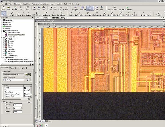
1 Overview MultiPrep Procedure TEM Wedge Preparation of an Integrated Circuit (IC) G.D. Liechty; E. Hirsch; C.A. Smith, Allied High Tech Products, Inc. August 2003 The MultiPrep is an efficient tool for preparing materials for TEM observation in either wedge or plan-view format. Samples are reliably polished to electron transparency, often eliminating the need for ion milling. Consistent sample rotation, oscillation and load provide uniform material removal and eliminate artifacts that can be associated with manual polishing. The dial preparation of multiple interfaces (i.e., thin films/superconductors). In this procedure, the polished (first) side of an IC (see cross-sectioning procedure) is mounted to a fixture with a Pyrex insert that has been polished parallel with the abrasive plane. The second side is thinned to remove bulk material. A wedge angle is then induced at 1 degree and the sample is final polished to electron transparency. The sample can then be ion milled or observed in the TEM. indicator measures the sample and allows the operator to monitor its thickness throughout the polishing process, decreasing preparation time by eliminating the guesswork associated with handheld polishing tools. Only the sample makes contact with the abrasive during polishing, ensuring that the desired angle (wedge polishing) remains intact throughout the process. The wedge technique provides a large, electron-transparent area in one dimension, making it ideal for semiconductors, and it allows simultaneous It is strongly recommended that the MultiPrep System manual be studied to ensure familiarity with the terms used to describe certain functions and components in this procedure. Consumable selection, machine settings and techniques used in this procedure were developed using the MultiPrep System in Allied s applications laboratory.
2 Equipment Used: MultiPrep System Cam-Lock Adapter TEM Wedge/FIB Thinning Paddle TechCut 4 Precision Low Speed Saw Zeiss Axioskop 2 MAT Compound Microscope w/ Transmitted Light Zeiss Stemi DV-4 Stereomicroscope Zeiss AxioVision 4 Measurement Software Note: Part numbers for microscopes and software depend on desired configuration. Consumables Used: Hot Mounting Wax Loc-Tite µm Diamond Lapping Film (DLF) µm DLF µm DLF µm DLF µm DLF Rubber Squeegee Red Final C Polishing Cloth µm Non-Crystallizing Colloidal Silica Suspension Micro Organic Soap Cotton-Tipped Applicators (Swabs) DLF Storage/Blotter Book Aero-Duster Canned Air Other: Hot Plate w/ Temperature Readout (Dataplate PMC 720) Microscope Slides Tweezers, Sharp End Acetone Isopropyl Alcohol Paper, 8 x 11 White Filter Paper 2
 and remove it to cool at room temperature. 3.")
. Photo 1 Photo 2 3 Photo 3 6. Place the slide onto the hot plate.")

3 Procedure 1. Place a microscope slide onto a hot plate set to 175 C. 2. Melt wax onto the slide, place the circuit side of the polished sample into the wax (Photo 1) and remove it to cool at room temperature. 3. Secure the slide into the saddle clamp and attach to the arm of the TechCut 4 (see Photo 2). Rotate the slide in the fixture so the circuit geometry is aligned with the edge of the blade. 4. Position the sample by adjusting the micrometer so the blade is approximately 1,000 microns from the polished edge. 5. Section through the sample and through the glass cover slip but not through the microscope slide (see Photo 3). Photo 1 Photo 2 3 Photo 3 6. Place the slide onto the hot plate. Once the wax is melted, remove the smaller sample and place it in a beaker of Acetone. 7. Swirl the sample thoroughly to remove the traces of wax. 8. Remove the sample from the Acetone and place it onto filter paper to absorb the Acetone for about 60 seconds. 9. Place the sample in a beaker of IPA (isopropyl alcohol) and swirl it for 20 to 30 seconds to remove the residual Acetone. 10. Remove the sample and place it onto filter paper to absorb the excess IPA for another 60 seconds. 11. With a cotton swab, clean the sample using a solution of Micro Organic Soap mixed with water (1:10). 12. Rinse the sample with water and dry using a clean air source such as an Aero-Duster. 13. Calibrate the MultiPrep System according to the procedures in the manual.
 and raise the arm using the vertical adjustment knob so the Pyrex does not touch the DLF.")
 until the Pyrex makes contact and the digital dial indicator displays at least 75 microns.")

4 14. Secure a 9µm DLF to the platen and set the sample load to full. 15. Using the cam-lock adapter, attach the TEM/Pyrex paddle (see below) onto the MultiPrep configured as shown in Photo 10. # , TEM/Pyrex Paddle 16. Lower the spindle with the spindle riser (if raised) and raise the arm using the vertical adjustment knob so the Pyrex does not touch the DLF. Zero the digital dial indicator by pressing the yellow button labeled Zero. 17. Activate platen rotation counterclockwise at 100 RPM. 18. Activate oscillation at speed Activate coolant and lower the paddle (using the vertical adjustment knob) until the Pyrex makes contact and the digital dial indicator displays at least 75 microns. Be sure to polish enough of the Pyrex so the entire surface is parallel with the platen. 20. Repeat steps using 3 µm DLF and polish the Pyrex for at least 3 minutes at 80 RPM. 21. Raise the spindle with the spindle riser. Remove the paddle and clean the polished surface of the Pyrex with IPA and dry using clean air. 22. Mount the sample to the Pyrex using either wax or glue. There are advantages with each method and only with trial and error will it be possible to determine the better of the two. Glue Wax 4


5 Glue method: Loc-Tite 460 is recommended for mounting the sample using this method. It is a very reliable and consistent product, more so than other similar products referred to as Super Glue or nail glues like Sally Hansen s. It is soluble in Acetone and requires no heat to cure. A. Position the paddle under the stereomicroscope as shown in Photo 4. B. Place the polished edge of the sample onto the polished Pyrex just behind the front edge until ready to glue it into position. C. Using the end of a toothpick or cotton-tipped applicator (wood end), apply a small amount of Loc-Tite 460 across the front, polished edge of the Pyrex. D. With tweezers, lift, place and position the sample as shown in Photo 5. E. Using firm but gentle pressure, press the sample against the Pyrex and squeeze the glue to produce a thin glue line. The sample should be mounted as close to and parallel with the front edge of the Pyrex as possible. F. Allow enough time for the glue to harden. Photo 4 Note: Using too much glue will prolong the cure time. Observe the glossy nature of the glue surface to determine if it is sufficiently hardened to continue. This may require remounting the sample a few times until the technique and amount of glue used is optimized. G. Once the glue is cured, measure the sample using AxioVision (Photos 6 and 9). Be sure to measure the thickest side of the sample if it is cut unevenly. Proceed to step 23 at this time. Photo 5 Photo 6 5

 on the slide (see Photo 8). C. Using tweezers, lift the cleaned sample and place the polished side into the wax.")
6 Wax method: A hot plate will be required to use wax. A stereomicroscope is used for viewing the sample when mounting it to the Pyrex. Note: Position the stereomicroscope close to the hot plate to shorten the distance when transferring the heated fixture. A heating block (# ) is used to prolong the heat to the Pyrex so the wax will remain liquid during mounting (see Photo 7). A. Place the TEM paddle, heating block and microscope slide onto the hot plate at 175 C. B. Melt a small amount of wax (a bead) on the slide (see Photo 8). C. Using tweezers, lift the cleaned sample and place the polished side into the wax. D. Lift the sample from the bead and place it next to the bead. Allow the wax to flow from the sides of the sample for about 10 seconds. E. Repe at about 3 times to new locations on the slide to remove the excess wax. F. Place the paddle onto the heating block and transfer the block to the stereomicroscope. G. Position the sample as shown in Photo 4 and press it into the Pyrex to compress the wax from between the sample and the Pyrex. The sample should be mounted as close to and parallel with the front edge of the Pyrex as possible. H. Remove the paddle from the heating block to cool for approximately 5 minutes. Once the wax is hard, measure the sample using AxioVision (Photos 6 and 9). Be sure to measure the thickest side of the sample if the sample is cut unevenly. Proceed to step 23 at this time. Wax Bead Photo 7 Photo 8 6


7 23. Place the paddle under the stereomicroscope. With a razor blade, remove the excess glue or wax from the glass cover slip where the sample is mounted to the Pyrex so that the sample may be observed in the microscope for measurement purposes. 24. Secure a 15 µm DLF to the platen. 25. Raise the arm more than the thickness of the sample using the vertical adjustment knob so that when the spindle is lowered with the spindle riser the sample does not touch the DLF. 26. Attach the paddle onto the cam-lock adapter (see Photo 10). Photo 9 Approximately 200 microns 27. Position the sample between the edge and the center of the platen (see Photo 10). 28. Set load to 300 grams. 29. Lower the spindle riser and zero the dial indicator. 30. Using the vertical adjustment knob, lower the sample into the abrasive until the digital dial indicator displays 100 microns more than what needs to be removed. For example, if 800 microns is to be removed, the dial should display 900 microns. Note: The objective is to stop so approximately 200 microns of the sample remains on the Pyrex using 15 µm DLF (see Photo 9). 31. Raise the sample using the spindle riser. 32. Activate platen rotation counterclockwise at 10 RPM. 33. Activate coolant and gently lower the sample onto the DLF using the spindle riser. Once contact is made between the sample and the abrasive, zero the dial indicator. Increase platen speed to 75 RPM, polish all but approximately 200 microns from the sample and raise the sample with the spindle riser. 34. Clean and measure the sample. Note: It may be necessary to increase the magnification to get a more accurate measurement. The polished edge will now be parallel with the Pyrex. 35. Secure a 6 µm DLF to the platen. 36. Polish the sample until it is about 100 microns thick. Repeat steps except use 60 RPM. 37. Stop the platen, raise the sample from the platen with the spindle riser and remove the sample for measurement and inspection. 38. Secure a 3 µm DLF to the platen. 39. Polish the sample until it is about 30 microns thick. 40. Repeat steps except use 40 RPM. Photo Stop the platen, raise the sample from the platen with the spindle riser and remove the sample for measurement and inspection. 7


8 Note: The sample is measured either by focusing through the glass cover slip on the circuitry or on the top of the cover slip. Measuring through the cover slip may create difficulty in determining the actual edge due to the reflection of light on the polished edge of the cover slip and the limited resolution. See Photos 11 and 12 to see the difference. Photo 11 Photo 12 Note: The desired angle may vary from sample to sample. However, when polishing IC s, a shallow angle is normally used so that every level of metal can be thinned from top to bottom. Too steep of an angle will not allow all the metals lines to be thinned entirely. 42. Using the vertical adjustment knob, raise the arm at least five (5) full rotations. Note: Because the angle adjustment will drive the front edge of the Pyrex closer to the platen, the arm of the MultiPrep must be raised. 43. Adjust the front left micrometer to the desired wedge angle by rotating it clockwise. Fifty vertical lines equal one full revolution and Secure a 0.5 µm DLF to the platen. 45. Attach the paddle, lower the sample with the spindle riser and zero the dial indicator. 46. Use the vertical adjustment knob and lower the sample into the abrasive until the digital dial indicator displays about 80 to 100 microns. 47. Raise the sample using the spindle riser. 48. Activate platen rotation clockwise at 10 RPM. 49. Activate the coolant and gently lower the sample onto the DLF using the spindle riser. Allow the sample to make contact with the DLF for one-half revolution, then lift the sample with the spindle riser. 50. Inspect the sample to determine if a facet angle is present. If parallel as in Photo 15, continue to step 55. Photo 13 Note: If the facet is not parallel with the circuit line as shown in Photo 13, the wax or glue line is either uneven or the sample is not mounted parallel with the front edge of the Pyrex. 51. Using AxioVision, measure the facet angle as shown in Photo 13. Using the value of the angle as measured, look up the necessary correction value in Graph #1. 8
. TEM Wedge Left to Right Correction Angle 0.02 Left/Right Correction Angle (LR) 0.24 0.22 0.2 0.18 0.")

9 52. Based on the sample measured in Photo 13, an adjustment to the right-rear micrometer will correct the facet angle on the sample used in this illustration, so it is parallel with the circuit line. The graph indicates the micrometer head requires adjustment by 0.05 degrees (2.5 ticks, see Photo 14). TEM Wedge Left to Right Correction Angle 0.02 Left/Right Correction Angle (LR) y = x Top View Angle (T) Graph 1 Photo 14 Note: Graph 1 applies to samples angled at 1. For other angles, multiply the wedge angle by the top view angle and multiply by Example: Top View Angle 2 Wedge Angle 4 x Equals 8 Multiply x 0.01 = 0.08 Represents the number if increments the micrometer head needs to be adjusted. 53. After the adjustment is made, polish the sample for another one-half rotation. 54. Raise the sample with the spindle riser and inspect it to verify accuracy of angle adjustment (see Photo 15). 55. When the facet is parallel, measure the sample thickness before proceeding with the final thinning (see Photo 16). 56. Attach and lower the paddle using the spindle riser and zero the dial indicator. 57. At 10 RPM, polish all but 10 microns from the sample and remove it to inspect under transmitted light (see Photo 17). Photo 15 9

. 59.")
10 Note: While thinning the sample with 0.5 µm DLF, eventually the front edge will thin to a point where it will no longer be possible to measure the thickness. The color of the sample will then be used to determine thickness. However, the digital dial indicator may still be used to monitor the polishing rate. 58. Once the sample is similar to that shown in Photo 16, return to the 0.5 µm DLF and remove 2 microns at a time until the glass cover slip begins to recede to an overall thickness between 50 and 75 microns (cross-section thickness, see Photo 17). 59. Apply a Red Final C polishing cloth to a separate platen and place it onto the TechPrep. 60. Remove the cam-lock adapter and attach the paddle on the underside of the micro-hub. Photo 16 Photo Set the limit sensors so the sample rotates to the approximate positions indicated in Figure Activate coolant and saturate the cloth. 63. Activate platen rotation clockwise at 150 RPM. 64. Activate Limit rotation at speed 1 (slowest). 65. Position the water flow at the edge of the platen to reduce colloidal silica splash on the bowl. 66. Apply 0.05 µm colloidal silica to the cloth. 67. With the vertical adjustment knob, lower the sample into the cloth until a trail is observed and the dial indicator displays between 20 and 30 microns, ensuring sufficient sample contact with the cloth. It may be necessary to add more colloidal silica to the cloth while lowering the sample so the trail can be observed. 68. Polish the sample in 1-minute intervals. Between intervals, clean and inspect the sample condition and progress. At the point where the glass recedes and approaches the circuitry, fringes will appear in the silicon. Platen Figure 1 10

11 At this point the sample can be thinned in the ion mill for a short period of time (under 5 minutes) to clean and remove artifacts. Continuing to polish the sample thinner can be more risky than ion milling to its final thickness. As operator skill level and familiarity with the MultiPrep increase, the sample can eventually be put into the TEM without ion milling. 200X Magnification, Transmitted Light 500X Magnification, Transmitted Light 11


12 Equipment Photo Page Stemi DV-4 TechCut 4 MultiPrep System AxioVision 4 Imaging/Capture Software Axioskop 2 MAT 12
MultiPrep Procedure. Backside Thinning of a Flip-Chip Device G. D. Liechty, C. A. Smith, Allied High Tech Products, Inc.
 MultiPrep Procedure Backside Thinning of a Flip-Chip Device G. D. Liechty, C. A. Smith, Allied High Tech Products, Inc., August 2003 Overview When thinning electronic devices for various analyses, including
TEM SAMPLE-PREPARATION PROCEDURES FOR THIN-FILM MATERIALS
 TEM SAMPLE-PREPARATION PROCEDURES FOR THIN-FILM MATERIALS Initial Set-Up: Heat up a hot plate to around 150-200 C Plan view Mounting/Grinding/Dimpling/Polishing: 1) Cleave a square-ish piece of sample.
XTEM sample prep for dummys. Nathan Gray University of Utah Materials Science and Engineering Graduate Research Assistant
 XTEM sample prep for dummys Nathan Gray University of Utah Materials Science and Engineering Graduate Research Assistant Necessary Equipment Epoxy: I used Mbond 610 available at Ted Pella. Also can use
Standard Operating Manual
 Standard Operating Manual Buehler EcoMet TM 300 Polisher Version 1.0 Page 1 of 19 Contents 1. Picture and Location 2. Process Capabilities 2.1 Cleanliness Standard 2.2 Possible Polishing Materials 2.3
Accessories for the Model 920 Lapping and Polishing Machine
 Accessories for the Model 920 Lapping and Machine Applications Laboratory Report Introduction polishing is a common practice in many materials preparation laboratories. Instrumentation for materials processing
Electron Microscopy Sciences
 Electron Microscopy Sciences INSTRUCTIONAL MANUAL CAT. 50120-10 Model 900 Grinding and Polishing Machine P.O. Box 550 s1560 Industry Road s Hatfield PA 19440 1 Introduction The Model 900 is a small, compact
Setting up and Using Digital Micrometer Controlled Lapping Fixtures
 Setting up and Using Digital Micrometer Controlled Lapping Fixtures Purpose polishing fixtures are commonly used in materials preparation labs around the world. Lapping fixtures provide stability, precision,
SUPERSEDED REVISION. Reasons for reissue of this instruction sheet are provided in Section 7, REVISION SUMMARY.
 PRO BEAM Jr. EB cable plug connectors are designed to be installed onto jacketed fiber optic cable with KEVLAR strength members. The connector must be assembled using a cable plug connector shell kit,
TechCut 5 PRECISION HIGH SPEED SAW. Product Brochure. Quality Products for Metallographic Sample Preparation & Analysis
 Product Brochure TechCut 5 PRECISION HIGH SPEED SAW A VERSATILE, PROGRAMMABLE SECTIONING MACHINE DESIGNED TO CUT A WIDE VARIETY AND SIZE OF MATERIALS Quality Products for Metallographic Sample Preparation
Dicing Through Hard and Brittle Materials in the Micro Electronic Industry By Gideon Levinson, Dicing Tools Product Manager
 Dicing Through Hard and Brittle Materials in the Micro Electronic Industry By Gideon Levinson, Dicing Tools Product Manager A high percentage of micro electronics dicing applications require dicing completely
Micro Automation- Model 1006 Dicing Saw Instructions. Serial # Rev 2 ( R.DeVito) Location Chase 1
 Location Chase 1") Micro Automation- Model 1006 Dicing Saw Instructions Serial # Rev 2 (12-23-05 R.DeVito) Location Chase 1 Dicing Saw Instructions (Revised 8/9/03 - K.J) 1. On the Log Sheet sign in, including Name and Date.
Micro Automation- Model 1006 Dicing Saw Instructions Serial # Rev 2 (12-23-05 R.DeVito) Location Chase 1 Dicing Saw Instructions (Revised 8/9/03 - K.J) 1. On the Log Sheet sign in, including Name and Date.
DualPrep 3 /PH Grinding/Polishing Systems
 Product Brochure DualPrep 3 /PH Grinding/Polishing Systems Intuitive Operation Durable, Powerful, Reliable 25 Programmable Steps Variable Platen and Sample Speed Central or Individual Sample Force Modes
Bath Accessory Installation
 Bath Accessory Installation Step 1 - Clean surface using a clean dry cloth or use rubbing alcohol to remove any residue (wax, grease, solvents). Allow to dry one hour. Caution! DO NOT use any household
MetPrep 4 /PH Grinding/Polishing Systems
 Product Brochure MetPrep 4 /PH Grinding/Polishing Systems Intuitive Operation Durable, Powerful, Reliable 25 Programmable Steps Variable Platen and Sample Speed Central or Individual Sample Force Modes
Termination Procedure
 Connector Piece Parts Contact/Connector Head Twist On Nut MX MX Boot Procedure Chart Procedure Tool Required Tool Part Number Cable Preparation & Fiber Cleaning Jacket Stripper 86710-0004 Cable Preparation
The World s Finest Skate Sharpening Equipment BLADEMASTER I-SH6000 OPERATORS MANUAL. REVISION DATE: September
 The World s Finest Skate Sharpening Equipment BLADEMASTER SH6000 OPERATORS MANUAL REVISION DATE: September 15 2010 I-SH6000 SH6000 SKATE SHARPENING FIXTURE WARNING: ALWAYS WEAR EYE PROTECTION WHEN OPERATING
1. Initial Precautions 2. Technical Precautions and Suggestions 3. General Information and Cure Stages 4. Understanding and Controlling Cure Time
 How to apply Arctic Silver Premium Thermal Adhesive 1. Initial Precautions 2. Technical Precautions and Suggestions 3. General Information and Cure Stages 4. Understanding and Controlling Cure Time 5.
Grinding and Polishing of Glass Samples for Cross Section Determination of Water Uptake
 Grinding and Polishing of Glass Samples for Cross Section Determination of Water Uptake Revised in 08/04 by Eric Hoke and in 10/08 by Xinwei Wu Original Procedure by Daniel MacNeil Tired of grinding and
Building a Slip Joint Folder By Steve Culver, Master Smith Part 1 of 2
 Building a Slip Joint Folder By Steve Culver, Master Smith steve@culverart.com www.culverart.com Part 1 of 2 This is part 1of 2 of Building a Slip Joint Folder by Steve Culver, Master Smith. This is a
CUTTING SAMPLES WITH THE BUEHLER PETROTHIN: USER GUIDE
 Cutting Sample with the Buehler PetroThin CUTTING SAMPLES WITH THE BUEHLER PETROTHIN: USER GUIDE Author: Reviewer(s): Management Approval (Name, Title, Date): Audience: E. Fisher Origination date: 4/29/2013
Kontax Stirling Engines KS90T instructions
 Kontax Stirling Engines KS90T instructions This document covers the following: Tools required Parts list Assembly instructions Operating instructions Maintenance Contact details: www.stirlingengine.co.uk
INSTRUCTION MANUAL. Force Transducer Output Tube Repair Kit
 INSTRUCTION MANUAL Model 400-TR Force Transducer Output Tube Repair Kit June 4, 2004, Revision 5 Copyright 2004 Aurora Scientific Inc. Aurora Scientific Inc. 360 Industrial Pkwy. S., Unit 4 Aurora, Ontario,
User Manual. Digital Compound Binocular LED Microscope. MicroscopeNet.com
 User Manual Digital Compound Binocular LED Microscope Model MD82ES10 MicroscopeNet.com Table of Contents i. Caution... 1 ii. Care and Maintenance... 2 1. Components Illustration... 3 2. Installation...
5. Carefully remove the printer from the lower boxed foam support and place it on a solid, level base where it will be used
 PROJET 1200 QUICKSTART GUIDE Before you get started you will need: Lint-free paper towels A pair of nitrile gloves Saftety glasses OPENING YOUR PROJET 1200 NOTE: Make sure you save all of your packaging
Installation Instructions 8115F 8115SF
 TM Installation Instructions 85F 85SF Single Control Centerset Lavatory Faucet with Speed Connect Drain Congratulations on purchasing your American Standard faucet with the Speed Connect Drain, a feature
Resistivity. First we will use a holder and wax. The main idea is to use the wax to glue the pellet to the holder.
 Resistivity Here we are going to indicate the necessary steps in order to see the sample preparation, the resistivity measurements procedure and the data analysis. Our sample made by Keeseong Park is BSCCO
Gently slide the roundnose chisel on the tool rest and into the grinding wheel. Like you practiced, pivot the chisel to grind the bevel.
 Set the roundnose chisel, bevel down on the tool rest. Slide the chisel forward until the center of the chisel touches the grinding wheel (Figure 24-21). With the machine "OFF" prac-tice pivoting the roundnose
Cleaning the cutter blade
 Cleaning the cutter blade < Daily maintenance > In order to use this printer in good condition, please perform the daily maintenance. Note the following when performing the maintenance. Do not lubricate
Flange Design & Maintenance
 Flange Design & Maintenance Back Flange S.S. Bushing S.S. Front Flange Al. + Hard Anodize Nut - S.S. Good Damaged Dicing Seminar Blade Gang Assembly s Dual blade Spacer Blade Wobbling Flange deflection
Kontax Stirling Engines KS90 instructions
 Kontax Stirling Engines KS90 instructions This document covers the following: Tools required Parts list Assembly instructions Operating instructions Maintenance Contact details: www.stirlingengine.co.uk
Improved Cooling unit with Automatic Temperature Controller for Enhancing the Life of Ice Bonded Abrasive Polishing Tool
 Improved Cooling unit with Automatic Temperature Controller for Enhancing the Life of Ice Bonded Abrasive Polishing Tool S.Rambabu 1 and N. Ramesh Babu 2 * 1 Department of Mechanical Engineering, Indian
Standard Operating Manual
 Standard Operating Manual NanoFactor NVG-200A Silicon Grinder Version 1.1 Page 1 of 18 Contents 1. Picture and Location 2. Process Capabilities 2.1 Cleanliness Standard 2.2 Possible Grinding Materials
Title: Precision Saw. Personnel performing this procedure will have training provided by the equipment manufacturer or by trained UF personnel.
 PAGE: 1 OF 5 Personnel performing this procedure will have training provided by the equipment manufacturer or by trained UF personnel. I. PURPOSE Put the purpose for this piece of equipment is to aid in
DISCO DICING SAW SOP. April 2014 INTRODUCTION
 DISCO DICING SAW SOP April 2014 INTRODUCTION The DISCO Dicing saw is an essential piece of equipment that allows cleanroom users to divide up their processed wafers into individual chips. The dicing saw
Pencil Hardness Tester BEVS 1301
 Pencil Hardness Tester BEVS 1301 User Manual PAGE 1 1. Introduction BEVS pencil hardness tester offers an easy to use method for the determination of film hardness for a coating applied to a flat substrate,
QUARTZ FABRICATION MANUAL
 QUARTZ FABRICATION MANUAL Quartz Fabrication Manual Rev. 1 Page 1 of 26 TABLE OF CONTENTS Product Description. 3 Slab Inspection.. 4 Fabrication Equipment.. 6 FABRICATION TIPS Cutting The Slab. 7 General
For Barrel Tapers. Installation and Operating Instructions for use with table saws and large disk sanders
 Tim s Taper Tool For Barrel Tapers Installation and Operating Instructions for use with table saws and large disk sanders Your taper tool is capable of making barrel tapered shafts. The term barrel is
Kontax Stirling Engines KS90S instructions
 Kontax Stirling Engines KS90S instructions This document covers the following: Tools required Parts list Assembly instructions Operating instructions Maintenance Contact details: www.stirlingengine.co.uk
PRINTED CIRCUIT BOARD (PCB) MICRO-SECTIONING FOR QUALITY CONTROL
 MICRO-SECTIONING FOR QUALITY CONTROL") SUMNotes PUBLISHED BY BUEHLER, A DIVISION OF ILLINOIS TOOL WORKS VOLUME 5, ISSUE 1 PRINTED CIRCUIT BOARD (PCB) MICRO-SECTIONING FOR QUALITY CONTROL Introduction Quality control in Printed Circuit Board
SUMNotes PUBLISHED BY BUEHLER, A DIVISION OF ILLINOIS TOOL WORKS VOLUME 5, ISSUE 1 PRINTED CIRCUIT BOARD (PCB) MICRO-SECTIONING FOR QUALITY CONTROL Introduction Quality control in Printed Circuit Board
Install Instructions for Corner Octavia Mantel
 Install Instructions for Corner Octavia Mantel Please read this manual before installing the suite. This manual should remain with the homeowner. 137 Nelson St Brantford Ontario Canada N3S 4B5 1-800-325-7988
Basic Users Manual for Tecnai-F20 TEM
 Basic Users Manual for Tecnai-F20 TEM NB: This document contains my personal notes on the operating procedure of the Tecnai F20 and may be used as a rough guide for those new to the microscope. It may
Wooden Faceplates. Tapping on the Lathe
 Wooden Faceplates There are lots of turning jobs where spending some time on set-up makes the turning go quicker and easier. Making Wooden Faceplates is one way to make set-ups and jigs for turning. As
LuxCore Installation Instructions
 LuxCore Installation Instructions ATTENTION: LuxCore PANELS MUST BE ACCLIMATIZED FOR 24 HOURS BEFORE INSTALLATION PLEASE READ ALL INSTRUCTIONS PRIOR TO INSTALLATION The guidelines provided herein have
M A N U A L 6 June 2017
 M A N U A L 6 June 2017 What are Protection Films? These films are meant to protect the vulnerable parts of cars, bicycles, motorbikes, etc... They are transparent glossy, so the underlying colour remains
A full range of abrasive and precision saws, blades, and vices for cutting any material.
 A full range of abrasive and precision saws, blades, and vices for cutting any material. SECTIONING Specimen preparation for microstructural examination starts with a quality cut. The proper equipment
INSTALLATION GUIDE VERSION 11/14
 INSTALLATION GUIDE VERSION 11/14 In this guide we will demonstrate effective techniques and methods for installing EDGE stainless steel sinks seamlessly in both laminate and solid surface. These techniques
General Wood Shop Notes
 General Wood Shop Notes Restricted Materials No METAL or BONE of any kind on any machine or in the room o See additional restrictions individual machine All reclaimed and other than new lumber must be
RISK OF SHOCK: DO NOT WIPE DOWN ANY ELECTRICAL COMPONENTS. ALWAYS KEEP AWAY FROM ALL AREAS WHERE ELECTRONIC COMPONENTS ARE INSTALLED.
 Maintenance General Cleaning Waste material from the printing process can accumulate inside the printer. Using a slightly damp, lint-free cloth, wipe the interior of the CubePro including the print plate,
Contents. pages 20-24: Installing Edge sinks into. custom laminate countertops page 8: Installing Edge sinks into postform laminate countertops
 Contents pages 2-8: Installing Edge sinks into custom laminate countertops page 8: Installing Edge sinks into postform laminate countertops pages 9-14: Installing Acrylic sinks into custom laminate countertops
TECHNICAL BULLETIN BELT FINISHING WITH MICRO-MESH
 TECHNICAL BULLETIN BELT FINISHING WITH MICRO-MESH MICRO-MESH finishing belts provide desired surface qualities and economic benefits to many types of finishing operations, and are available in a range
UNPACK & ASSEMBLY. Done! CAUTION! THE MILL WILL BE VERY HEAVY - GET ASSISTANCE Pepe Tools.
 PARTS DIAGRAM T Bar Height adjustment Wooden hand grip Height adjustment gears Frame Height adjustment screws Top roller End Gears cover Handle Brass Bushes (Each side) Bottom roller 4:1 Gearbox Mounting
Assembly Instructions: Kit #5
 Assembly Instructions: Kit #5 1. Insert the T-pin into one of the caps. 2. Insert the rotor core into the same cap as shown below. Apply some pressure to push the rotor core approximately 1/2" (10-12 mm)
TABLE OF CONTENTS. Safety notes i. Care and Maintenance. ii. 1. Components Illustration Installation of Components.. 4
 TABLE OF CONTENTS Safety notes i Care and Maintenance. ii 1. Components Illustration... 1 2. Installation of Components.. 4 2.1 Installation Diagram... 4 2.2 Installation Procedures 5 3. Operation...11
Kontax Stirling Engines KS90R instructions
 Kontax Stirling Engines KS90R instructions This document covers the following: Tools required Parts list Assembly instructions Operating instructions Maintenance Contact details: www.stirlingengine.co.uk
3M Impact Protection Profile Installation System Instructions
 3M Impact Protection Profile Installation System Instructions IMPORTANT: READ INSTRUCTIONS FOR USE BEFORE OPERATING Intended Use: The 3M Impact Protection Profile Installation System is for installing
REQUIRED EQUIPMENT SETUP
 #003-598 raverhone VS OPERATION AND MAINTENANCE MANUAL 24V IMPORTANT NOTICE FOR OPERATORS No user serviceable parts inside. Do not remove any outer surfaces. Do not modify this equipment or remove warning
Casting Tool Kit, from Jewelry Television. Introduction. Tools That Come With The Casting Kit
 Tools That Come With The Casting Kit 1. 2. 3. 4. Stone Setting Pliers Pin Vise Prong Lifter 80mm Brass Gauge 5. 6. 7. 8. Tweezer Burnisher Prong Pusher Ring Clamp Casting Tool Kit, from Jewelry Television
Figure 1. Oil-immersion objectives available for use with the Lionheart FX.
 Tech Note Oil Objective Introduction The Lionheart FX automated imager is compatible with high numerical aperture oil immersion objectives. These objectives offer magnification up to 100X and significantly
Curium 19H Installation Instructions & Parts List
 Curium 19H Installation Instructions & Parts List Illustration Curium 19H Right Hand Page 1 of 15 01/07/2016 Revision 2.1 IMPORTANT This shower screen / enclosure must be installed by suitably qualified
Display-Top Apothecary Cabinet. Assembly Instructions. Page 1
 Display-Top Apothecary Cabinet Assembly Instructions Page 1 Display-Top Apothecary Cabinet Parts List Please check packaging for all parts and hardware before discarding. Unpack and lay parts on clean,
Ox-RAC-08 Ribbon Angled Fiber Cleaver User Manual
 Ox-RAC-08 Ribbon Angled Fiber Cleaver User Manual Issue 2.0 Contents Introduction... 2 Contents of Cleaving Kit & Unpacking... 3 Cleaving Problems... 8 Blade damage:... 9 Cleaver Maintenance... 10 Cleaning
1 SELECT suitable material. It takes time to cut a cab. Don t waste it on rubbish.
 7 July 09 CUTTING A STANDARD CABOCHON A Standard Cabochon or CAB is an oval or round stone with one flat side and the other side having an even curved dome shape. Top of Cab It will have a narrow bevel
Semiconductor Back-Grinding
 Semiconductor Back-Grinding The silicon wafer on which the active elements are created is a thin circular disc, typically 150mm or 200mm in diameter. During diffusion and similar processes, the wafer may
UNPACK & ASSEMBLY. Done! CAUTION! THE MILL WILL BE VERY HEAVY - GET ASSISTANCE Pepe Tools.
 PARTS DIAGRAM T Bar Height adjustment Wooden hand grip Height adjustment gears Frame Height adjustment screws Top roller End Gears cover Handle Brass Bushes (Each side) Bottom roller 4:1 Gearbox Mounting
MICROSCOPE LAB. Resolving Power How well specimen detail is preserved during the magnifying process.
 AP BIOLOGY Cells ACTIVITY #2 MICROSCOPE LAB OBJECTIVES 1. Demonstrate proper care and use of a compound microscope. 2. Identify the parts of the microscope and describe the function of each part. 3. Compare
COMPOSITES LAB MANUAL
 COMPOSITES LAB MANUAL Version 1 Lab 3: Surface Preparation, Wet Layup, and Vacuum Bagging The original version of this manual was a one student senior design project written by Katherine White, the Composite
THIS SHEET CONTAINS IMPORTANT SAFETY INSTRUCTIONS. SAVE THESE INSTRUCTIONS.
 LumeLEX 2026 SERIES INSTALLATION INSTRUCTIONS Important THIS SHEET CONTAINS IMPORTANT SAFETY INSTRUCTIONS. SAVE THESE INSTRUCTIONS. Warning This product must be installed in accordance with National Electrical
Laboratory Introduction
 Laboratory Introduction There are two basic categories of microscopes: light microscopes and electron microscopes. Light, or optical, microscopes require light waves to provide the illumination while electron
3M No Polish SC/APC Angle Splice Connector Jacket for 2 x 3 mm FRP and 1.6 to 3.0 mm Cable 8802-T/APC/AS/1.6-3
 3M No Polish SC/APC Angle Splice Connector Jacket for 2 x 3 mm FRP and 1.6 to 3.0 mm Cable 8802-T/APC/AS/1.6-3 Instructions October 2013 3 1.0 Table of contents 1.0 Summary...3 2.0 Cable and Fiber Preparation...4
Application of 3M Pressure Sensitive Films to 3M Panagraphics Substrates
 Instruction Bulletin 5.30 Release B, Effective October 2006 See bulletin change summary on last page Application of 3M Pressure Sensitive Films to 3M Panagraphics Substrates Preparation Points to Consider
SCREEN PRINTING V0.3 DRAFT. Not for Release STANDARD OPERATING PROCEDURE
 V0.3 DRAFT SCREEN PRINTING STANDARD OPERATING PROCEDURE Not for Release Professor Chris Bondy, School of Media Science, RIT Akshat Pardiwala, Graduate Student, MS, Print Media Mitchell Morgan, Undergrad
A socket contact support (supplied separately) must be installed onto the locator assembly.
 must be installed onto the locator assembly.") Figure 1 PRO CRIMPER III Hand Tool Assembly 1976444 1 consists of PRO CRIMPER III Hand Tool Frame 354940 1 and Die Assembly 1976444 2. The tool assembly is used to crimp the contacts listed in Figure 1.
Figure 1 PRO CRIMPER III Hand Tool Assembly 1976444 1 consists of PRO CRIMPER III Hand Tool Frame 354940 1 and Die Assembly 1976444 2. The tool assembly is used to crimp the contacts listed in Figure 1.
Adhesive Application & Laminating System
 U S E R S G U I D E Adhesive Application & Laminating System The XM2500 is an economical and easy to use document finishing system. This versatile and non-electric system has been designed to laminate
PRECISION CUTTING MICRACUT 202
 PRECISION CUTTING MICRACUT 202 MICRACUT 202 MICRACUT 202 precision cutters are used for precise and deformation-free cutting of Metals, Ceramics, Electronic Components, Crystals, Composites, Biomaterials,
2 How to operate the microscope/obtain an image
 Morgagni Operating Instructions 50079 010912 2-1 2 ow to operate the microscope/obtain an image 2.1 Starting the microscope 2.1.1 Starting the microscope with several manually-operated steps 1. Turn on
8.10 Drill Grinding Device
 8.10 Drill Grinding Device Special Accessories 1. Introduction Device can accurately grind precision drill and tools, this drill grinding machine system consists of a motor and grinding wheel head composed
Metal Aircraft Landing Light Installation Instructions
 Metal Aircraft Landing Light Installation Instructions This landing light kit was designed for the Thorp T-18 as a method of installing a halogen landing light in the leading edge of the outer bay of the
tile redi redi DOOR Redi Redi Swing Slide g TM TM...Opening Doors to Stunning Showers! TM TM SERIES: CONFIGURATION: MOUNTING PACKAGE:
 redi DOOR INSTALLATION INSTRUCTIONS tile redi Redi Redi Swing Slide g TM TM...Opening Doors to Stunning Showers! TM TM SERIES: CONFIGURATION: MOUNTING PACKAGE: 3000 Door-Door Header, sliding doors RDQCI5301
An improved technique for producing thin rock-sections.
 247 An improved technique for producing thin rock-sections. By A. C. BisHoP, B.Sc., Ph.D., F.G.S. Department of Geology, Queen Mary College, University of London. [Taken as read 7 June 1962.] Summary.
Installation Instructions
 GENERAL INSTALLATION INFORMATION To ensure maximum performance from your A 2 bath fixture, please read and follow the instructions and cautions. Carefully inspect the new fixture for any shipping damage.
Laboratory 2: Microscopy and Observation of Cells authors: Dr. Ruth Dahlquist-Willard & Michael Kunz
 Laboratory 2: Microscopy and Observation of Cells authors: Dr. Ruth Dahlquist-Willard & Michael Kunz Corresponding Readings: Campbell Ch. 4 BIOL-100L Safety Information: We will be using laboratory glassware
XHD Bull Bar w/ Dual Row LED Light Bar (10-17 Jeep JK)
") XHD Bull Bar w/ Dual Row LED Light Bar (10-17 Jeep JK) PARTS LIST: 1 Driver/Left Side Bull Bar Upright 8 10-1.5mm Hex Nuts 1 Side Bull Bar Upright 4 10-1.5mm Nylon Lock Nuts 1 Top Cross Bar 2 Light Bar
XHD Bull Bar w/ Dual Row LED Light Bar (10-17 Jeep JK) PARTS LIST: 1 Driver/Left Side Bull Bar Upright 8 10-1.5mm Hex Nuts 1 Side Bull Bar Upright 4 10-1.5mm Nylon Lock Nuts 1 Top Cross Bar 2 Light Bar
PRECISION, VERSITALITY, & CONSISTENCY
 SMART CUT 6001 GP SECTIONING SAW Operator can change the feed rate and blade speed during operation Can be used for highest precision applications and for general low deformation, low kerf loss sectioning
Timing the Millennium, Freedom, Liberty and Discovery
 Timing the Millennium, Freedom, Liberty and Discovery Use these instructions in conjunction with your instructional CD. Symptoms: Skipping or missing stitches. Solution: Change needle. (We strongly recommend
Instruction Sheet MCHE 365 & I-Tech 344 Lathe & Mill Machining Operations Pencil Organizer Project, FALL 2015
 Instruction Sheet MCHE 365 & I-Tech 344 Lathe & Mill Machining Operations Pencil Organizer Project, FALL 2015 1 Always flip to 1 st page & leave your drawings & instructions on your Machine at end of class.
Clamping filigree parts
 Clamping filigree parts August 2005 Getting a good hold on bits and pieces For almost all shapes and sizes of parts there are suitable clamping technologies available on the market. However demands on
Agricultural Mechanics and Technology Power Tool Safety Rules
 Agricultural Mechanics and Technology Power Tool Safety Rules Name: BAND SAW Use: Cutting curves, circles and irregular shapes. 1. Use clean SHARP blades. 2. The teeth should always point DOWN. 3. Adjust
To install new top weight plate bushings in G7 strength units.
 1/5 PURPOSE To install new top weight plate bushings in G7 strength units. RE-WORK PARTS REQUIRED - ZMS4000424 Top Weight Plate Bushing (Quantity 4 per machine). - Matrix Top Weight Plate Bushing Removal
Wedge Bonder --- West Bond E
 Wedge Bonder --- West Bond 747677E Figure 1: West Bond Wedge Bonder Introduction The West Bond 747677E bonder is an ultrasonic wedge-wedge wire bonder designed to interconnect wire leads to various types
Materials Polishing Manual. By Thomas Perry Daniel Webster College Version 1 August 10, 2007
 Materials Polishing Manual By Thomas Perry Daniel Webster College Version 1 August 10, 2007 Materials Polishing Manual This manual describes how to use the equipment at Daniel Webster College to create
Curium 19.4H Installation Instructions & Parts List
 Curium 19.4H Installation Instructions & Parts List Illustration Curium 19.4H Right Hand Page 1 of 21 30/06/2016 Revision 1.0 IMPORTANT This shower screen / enclosure must be installed by suitably qualified
Instructions for Catalina Round/Square Extension Tables
 Unpack the table onto a soft level surface and identify the listed items. Instructions for Catalina Round/Square Extension Tables Hardware included: ¼ - #20 x 35mm s (4) ¼ - #20 x 50mm s (8) Cross nuts
Commonwealth of Pennsylvania PA Test Method No. 517 Department of Transportation October Pages LABORATORY TESTING SECTION. Method of Test for
 Commonwealth of Pennsylvania PA Test Method No. 517 Department of Transportation 10 Pages 1. SCOPE LABORATORY TESTING SECTION Method of Test for DETERMINATION OF ACCELERATED POLISH OF COARSE AGGREGATE
SUPERSEDED. NOT the LATEST REVISION
 Figure 1 OPTIMATE 2.5mm bayonet ceramic connector kits listed in Figure 1 are designed to be applied to fiber optic cable. Coupling Receptacle Kit 501381 1 is used to mate two bayonet connectors in free
Repair Instructions. Durametallic PSS III. Experience In Motion. Split Seal
 Repair Instructions Durametallic PSS III Split Seal Experience In Motion PSS III seal reference Gland Gland Gasket Split Joint gasket Coil Spring Seal Drive Sleeve Gasket Split Joint Gasket Rotating Face
OPERATING INSTRUCTIONS FOR MODEL SPR-25 Manual Stencil Printer
 OPERATING INSTRUCTIONS FOR MODEL SPR-25 Manual Stencil Printer TABLE OF CONTENTS I. INSTALLATION...3 II. SET-UP...4 III. Z AXIS ADJUSTMENT (Screen Height)...6 IV. X, Y AND Ø ADJUSTMENTS...6 V. SQUEEGEE
FBX-PA-2AC. Third edition : April No
 FBX-PA-2AC Third edition : April 2006 No. 060058 INTRODUCTION Thank you very much for purchasing Kansai Special FBX series. Read and study this Instruction Manual carefully before you start any of the
Owners Manual for. The Transcriptor. Skeleton Turntable
 Owners Manual for The Transcriptor Skeleton Turntable Owner's Manual for The Transcriptor Skeleton Turntable - 1 - E X C L U S I V E U N I T E D S T A T E S I M P O R T E R A N D D I S T R I B U T O R
Traditional Undermount: S Method (Undermount):
:") TOOLS REQUIRED 15.1 TOOLS REQUIRED The installation of Corian shape product must be a precise and exacting process to ensure that a good fit is always created. Using the correct tools is essential. In
TOOLS REQUIRED 15.1 TOOLS REQUIRED The installation of Corian shape product must be a precise and exacting process to ensure that a good fit is always created. Using the correct tools is essential. In
Troubleshooting Conventional Burnout Phosphate Bonded Investments
 Troubleshooting Conventional Burnout Phosphate Bonded Investments Phosphate investments are affected by many variables, but the following generalizations can be made: Thorough mixing insures complete reaction