A Case study for near net Shape Flashless forging for full yoke (Sleeve Yoke OMNI)
|
|
|
- Crystal Mitchell
- 6 years ago
- Views:
Transcription
1 International OPEN ACCESS Journal Of Modern Engineering Research (IJMER) A Case study for near net Shape Flashless forging for full yoke (Sleeve Yoke OMNI) Er. O. P. Dwivedi 1, Er. Dharminder singh 2 1 (GM (mfg) GNA UDYOG Ltd, Bundala, M. tech (P/T) RIET/PTU, Phagwara/jalandhar,Punjab,India) 2 (Lecturer in Ramgharia polytechnic Phagwara, M. tech (P/T) PTU, jalandhar) Abstract: Forging is a metal forming process commonly used in industry. Forging process is strongly affected by the process parameters. In a progressive press forging process, an initial block of metal (billet) is compressed between two dies halves in each stage to produce a complex part. The shape of the initial billet is crucial in achieving the desired characteristics in the final forged part. The metallurgical property as well as the geometry of the final product are strongly dependent on the shape of initial work piece as well as on the perform shapes at each of the subsequent forming stages. The major issue, which restricts imparting large deformation to the billet are the tensile stress, which later results in cracking. Bulge is also undesirable from near net shape manufacturing point of view, as it will require secondary processing like trimming Traditionally, an experienced designer uses his or her expertise and design data handbooks for optimizing the initial billet shape. Design of the optimum preform for near net shape forging is a crucial step in the design of many forging products In this study, the same is arrived at using profile map, which is generated using the results of FE simulations of varying geometrical and processing parameters.it is shown that preform map offers a powerful tool for near net shape forging Keyword: finite element,preform, press forging; profile map; near net shape I. Introduction 1.1 In metal forming process, Net shape forging can be defined as the process of forging components to final dimensions with no post forging machining necessary. Near-net shape forged components, on the other hand, are forged as close as possible to the final dimensions of the desired part, with little machining or only grinding [1] after forging and heat treatment. Automotive industry is the main customer of near net shape forging components. Today's market is characterized by requirements for short delivery times, low costs and high quality. The supplier is confronted with smaller production and delivery batch sizes and an increasing type variation of part types. Automobile producers are more and more interested in parts which need minimal machining or are ready to assemble. Near Net shape forging parts can fulfill these requirements. The preform design used in near net shape forging processes is an important aspect for improving product quality and decreasing production cost. In the past, preform design was accomplished by empirical design, approximate analysis and trial-and-error. This task is now supported by the finite-element method and the backward tracing scheme [2]. Preform is material part that has undergone preliminary shaping but is not yet in its final form. In preform all process parameter and part geometry is defined in advance by which near net shape is easily found. through the use of simulation technique. This computer- aided simulation will reduce number of expensive die tryouts[3] 1.2 Background: This product is the main part in propeller shaft's universal joint as shown in PHOTO 1. In PHOTO 1(a) the final product full yoke is presented. The product is forged in 4 multistage [4] operation steps. Each operation consists of a stroke between a male and female die. The 4 multi stage-operation method is based on the flashless die technology, developed in the press forge [4]. Flashless forging technology means that the external material during production is as less as possible. Earlier the part is manufactured by drop forging process in three stages (fullering, blocker and finisher) as shown in Fig 2. Design is provided with minimum of 15% flash margin and 1.5mm minimum machining allowances per side which can be controlled to 3% flash and 0.5mm machining margins per side by flashless/near net shape forging concept.fig. 2a and Fig. 2b shows the old hammer dies and produced forging part. IJMER ISSN: Vol. 4 Iss. 4 Apr
 Prop.")
 Old Drop forging die")

2 Photo 1 1, Photo 1 2 Fig 1a Prop. Shaft Omni Photo (1) Prop. Shaft Omni Photo (1a) Final forged part Fig (2a) Old Drop forging die design Fig (2b) Drop forged part IJMER ISSN: Vol. 4 Iss. 4 Apr
 STAGE -2 (Fullering)")
 STAGE -4 (Finished) Comparison Table 1")
 1.450 0.")
 2000 340 Allowances!")
3 Fig (3a) STAGE -1 (Blank) Figures showing the Drop forging process stages Fig (3b) STAGE -2 (Fullering) Fig. (3c) STAGE -3 (Blocker) Fig. (3d) STAGE -4 (Finished) Comparison Table 1 Parameters Drop Hammer FE Model Material C-45 C-45 Blank weight (kg) Blank size (mm) Φ50 Ҳ 84 Φ 48Ҳ70 Temperatu( c ) Max Load (N) Allowances!5% 3% IJMER ISSN: Vol. 4 Iss. 4 Apr

 & (4b) 1.")
 Fig (4a) STAGE -1 1.3.1.2 Operation 2 Turning the vertical piece at right angle and slight upset so that the sufficient material is achieved for yoke filling up. Fig (4b) STAGE -2) 1.3.1.3 Operation 3 Again turning the piece to right angle and forging it to final shape.")
4 1.3 Design Research Design Research 1 To achieve near net shape / flash less forging, the design was changed to vertical forging where the contact area between the top punch, bottom die and the work piece was minimized so that minimum flash could be achieved [5}.To achieve this Preform Design it was conceptualized that the stem portion will be in one cavity only and there would be no contact of the other half of the die.the other half which would be in contact and where there will be flash formation will only be in the yoke portion. So the conceptualized photo is as shown in the Fig.(4a) & (4b) Operation 1 Gathering or upsetting is done in the top head keeping the stem diameter same which is as per the volume required for making yokes with 3% (Burning and Flash) allowance as shown in Fig (4a) Fig (4a) STAGE Operation 2 Turning the vertical piece at right angle and slight upset so that the sufficient material is achieved for yoke filling up. Fig (4b) STAGE -2) Operation 3 Again turning the piece to right angle and forging it to final shape. Result: - The yoke found unfilled and huge flash formed unevenly as shown in the Fig (4c) Fig. (4c) STAGE -3 IJMER ISSN: Vol. 4 Iss. 4 Apr

 to (5e) 1.3.2.")
 Fig (5b) Stage -1 (forward extrusion- FE")
 T formed IJMER ISSN: 2249 6645 www.ijmer.")
5 1.3.2 Design Research 2 To overcome the problem of underfilling and excess flash in design research 1, design research 2 was coceptualised as shown below from Fig (5a) to (5e) Design and development approach Fig (5a) Stage -0 (billet) Fig (5b) Stage -1 (forward extrusion- FE model) Fig (5c) stage2 T- formation (FE model) Fig(5c) T formed IJMER ISSN: Vol. 4 Iss. 4 Apr
 II.")

6 Fig (5d) Stage -3 Bending of T (FE model) Fig (5e) Stage -4 (Finished yoke) II. Methodology Methodology followed during the tenure of this study is given in the form of flowchart as followed- Flow chart 1 IJMER ISSN: Vol. 4 Iss. 4 Apr
 T- Shape (2 nd stage) Bend shape (3 rd stage) Final near net shape ( 4 th stage) Flow Chart 2 Fig. 6 a (Near net shape Forged Part) Fig.")
7 III. Production Flow Diagram Material Inspection Billet Cut Weight gm Billet dia 49mm Graphitisation Heating Temp. 950 ± 50 C Forward Extrusion (1 st stage) T- Shape (2 nd stage) Bend shape (3 rd stage) Final near net shape ( 4 th stage) Flow Chart 2 Fig. 6 a (Near net shape Forged Part) Fig. 6 b (FE Model) IJMER ISSN: Vol. 4 Iss. 4 Apr

8 Fig 7a (Four stages die design) IV. Deform Simulation / FE Models The FE model for all four stages consist of three parts i.e. top, bottom and partgeometry. Part geometry [6] used in each operation is the outpui of previous operation. The top and bottom dies are selected as rigid bodies while the part is in plastic form. Because the die blocks have to retain their shape. In Table 2 the friction parameters [7] in all stages are presented: Stage 1 Stage 2 Friction Heat Transfer Friction Heat Transfer Contact Coefficient Coefficient Contact Coefficient Coefficient Lower die (N/sec/mm/C) Lower die (N/sec/mm/C) Upper die (N/sec/mm/C) Upper die (N/sec/mm/C) Piece (N/sec/mm/C) Piece (N/sec/mm/C) Stage 3 Stage 4 Friction Heat Transfer Friction Heat Transfer Contact Coefficient Coefficient Contact Coefficient Coefficient Lower die (N/sec/mm/C) Lower die (N/sec/mm/C) Upper die (N/sec/mm/C) Upper die (N/sec/mm/C) Piece (N/sec/mm/C) Piece (N/sec/mm/C) Table 2 V. Production explanation In this chapter, the complete production of product (full yoke) will be explained. All the possible problems that appear in the production will be described. Each operation is defined clearly so a good idea about the main problem of this subject can be made 5.1 Preparation: The starting product consist of a steel alloy cylinder with a diameter of 48 [mm] and a height of 70 [mm]. The cylinder will be called in the future piece. The piece is preheated in an induction furnace till it has the temperature of 950 C. This means also that the volume of the epiece changes because of the big temperature difference. With the formula the new volume can be calculated. (1) With expansion coefficient α= [1/K] and T = 950 [K], the diameter increases to [mm] and the height increases to [mm]. So these lengths have to be used in the FE model well as in first operation die, After heating the cylinder cools for 18 seconds, because in that time the cylinder is transported from the induction heater to the first operation place, After that the piece has to be placed in the center of the die of the first operation, this is very important for the good centering of the product. This takes atleast 1.5 secs. The 19.5 secs of transportation and cooling has to be simulated as well in the numerical simulation IJMER ISSN: Vol. 4 Iss. 4 Apr
![5.2 operaration1: After positioning of the piece, the first stroke takes place. This operation is the forward extrusion operation [8] and has a couple of aims.](/docs-images/77/75863140/images/9-0.jpg "First of all it removes the scale and redistribute the material to the shape of the end product. Next to that, it also rejects the piece if the weight tolerance is exceeded.")

9 5.2 operaration1: After positioning of the piece, the first stroke takes place. This operation is the forward extrusion operation [8] and has a couple of aims. First of all it removes the scale and redistribute the material to the shape of the end product. Next to that, it also rejects the piece if the weight tolerance is exceeded. Because if the weight tolerance is exceeded, the piece will not fit in the die of the second operation. Further it ensures the exact positioning in the die of the second operation The final distance between the upper and lower die is [mm]. In figure7(a), the upper and lower dies of operation 1 are presented. The parameters, which can be changed for the research, are given in Fig( 7a ),Only the height can be changed, because by changing the height, also the angle shall change. This will ensure to keep the same volume between the two dies In Fig ( 8a) the filling of the original geometry after operation 1 is presented. After the stroke, the upper die will go up and the piece will be transported to the lower die of operation 2. This takes 1.5 seconds and in this time, the piece will cool again. IJMER ISSN: Vol. 4 Iss. 4 Apr

 0.")
 39.")
")
 725 1016 5")
 48.95130 98.")
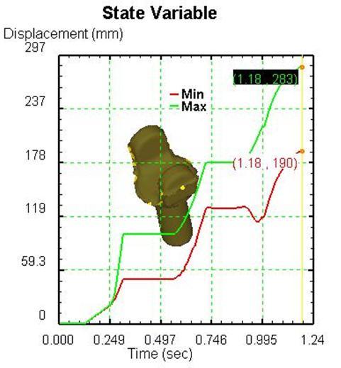
10 Table 3 State variable parameters for Stage 1 Stage1 Sr. No contents minimum value maximum value 1 Effective Strain (mm/mm) Effective Stress (Mpa) Effective Strain rate (mm/mm/sec) Temperature ( 0 C) Volume (mm 3 ) Displacement (mm) Velocity (mm/sec) Fig. 8b State variable & graph for operation 1 IJMER ISSN: Vol. 4 Iss. 4 Apr

, the upper and lower dies of operation 2 are presented. In this operation a lot of parameters can be changed.")

11 5.3 operation 2: After the transportation of the operation1, the piece will be placed in the lower die of operation 2, which also takes 1.5 seconds. The second operation is the preforming operation in T shape and has also a couple of aims. First of all it creates arms equal to calculated length of forks the side walls of the die would restrict the flow of material and control the width of forks without any flash. Thickness of forks can be adjusted by adjusting the stroke length In Fig( 9a), the upper and lower dies of operation 2 are presented. In this operation a lot of parameters can be changed. This is also the reason that the solution first has to be found in the second operation. Now the second stroke takes place. The final distance between the upper and lower die depends on the filling of the point where the upper and lower die comes together. See the arrow at Fig ( 9a ) The filling of the corner has to be approximately the same as the filling in Fig( 5c). A shape in the corner like that, gives a good filling in the top of the die and also a good flashless filling at the end of operation 4. Table 4 State Variable parameters for Stage 2 SR.NO CONTENTS MINIMUM VALUE MAXIMUM VALUE 1 Effective strain(mm/mm) Effective stress(mpa ) Effectivestarin rate(mm/mm/sec) Temeperature( c) Volume (mm³) Displacment(mm) Velocity(mm/sec) IJMER ISSN: Vol. 4 Iss. 4 Apr

, the upper and lower dies of operation 3 are presented.")


12 Fig. (9b) State variable graph for operation Operation 3 After the operation 2, the piece will be transported in the lower die of operation 3, which also takes 1.5 seconds. In Fig ( 10a), the upper and lower dies of operation 3 are presented. In this operation only one parameter can be changed. This because of the fact that the shape of the end product is prescribed. Now the third stroke takes place. The final distance between the upper and lower die depends upon the proper bending of piece in the die. If the whole die is filled, it isn't necessary to press further. In DEFORM [9] this is easily seen with the graphical function of the normal pressure. IJMER ISSN: Vol. 4 Iss. 4 Apr

 0.37700 6.0200 2 Effective stress(mpa ) 0.17 282.")
 589.00 1020.00 5 Volume (mm³) 131704.")
 490.1200 680.")
13 Fig 10a FE Model of die in closed condition and perform after bending of T STAGE 3 SR.NO CONTENTS MINIMUM VALUE MAXIMUM VALUE 1 Effective strain(mm/mm) Effective stress(mpa ) Effectivestarin rate(mm/mm/sec) Temeperature( c) Volume (mm³) Displacment(mm) Velocity(mm/sec) Table 5 : Stage Variable Parameters for Stage 3 IJMER ISSN: Vol. 4 Iss. 4 Apr


14 Fig. 10b State variable graph for operation 3 IJMER ISSN: Vol. 4 Iss. 4 Apr

15 5.4 operations 4 After the Operation 3, the piece will be transported in the lower die of operation 4, which also takes 1.5 seconds. In figure 7, the upper and lower dies of operation 4 are presented. In this operation only one parameter can be changed. This because of the fact that the shape of the end product is prescribed. Now the fourth stroke takes place. The final distance between the upper and lower die depends on the filling of the top of the die. If the whole die is filled,and the total length is achieved it isn't necessary to press further. In DEFORM 3D this is easily to see with the graphical function of the normal pressure. Table 6 State variable parameters for stage 4 SR.NO CONTENTS MINIMUM VALUE MAXIMUM VALUE 1 Effective strain(mm/mm) Effective stress(mpa ) Effectivestarin rate(mm/mm/sec) 4 Temeperature( c) Volume (mm³) Displacment(mm) Velocity(mm/sec) IJMER ISSN: Vol. 4 Iss. 4 Apr


16 IJMER ISSN: Vol. 4 Iss. 4 Apr
 (mm) Dimensions Obtained Throughflashless forging route (Press forging)(mm) 1 69.5 67.91 2 40.00 41.00 3 70.50 67.60 4 58.")
17 Observation A Case study for near net Shape Flashless forging for full yoke (Sleeve Yoke omni) Fig. (11 b) State variable Graph for operation 4 VI. Result & Comparison Sr No Dimensions Obtained Through( hammer forging route) (mm) Dimensions Obtained Throughflashless forging route (Press forging)(mm) Table 7 Dimensional Comparison Full Yoke (Omni) Dimension No. Drop Hammer Flass less Forging IJMER ISSN: Vol. 4 Iss. 4 Apr
 PRESS (1500 TON) 68 kgf/mm² 79 kgf/mm² IMPACT 22 Joule 44 Joule GRAIN")
 IJMER ISSN: 2249 6645 www.ijmer.com Vol. 4 Iss.")
18 6.1 Metallurgical Test Reports and Comparison DATE METALLURGICAL PROPERTIES Graph 1 HAMMER 17/9/2012 HARDNESS 197 BHN 229 BHN TENSILE (DATA AS PER HARDNESS VALUE) PRESS (1500 TON) 68 kgf/mm² 79 kgf/mm² IMPACT 22 Joule 44 Joule GRAIN SIZE 6-8 ASTM 5-8 ASTM GRAIN FLOW OK OK Table 8 Photo 2 (Micro Structure of Hot Forging on Hammer) Photo 3 (Micro Structure of Near Net Shape forging on 1500MT Multi Station Press) IJMER ISSN: Vol. 4 Iss. 4 Apr
19 Input Weight. Forged (wt. With flash) Net wt. Flash wt. Burning Loss % Flash % Burning % Yield Value A Case study for near net Shape Flashless forging for full yoke (Sleeve Yoke omni) 6.2 Weight saving Economics Reports and comparison WEIGHT SAVING ECONOMICS SR.NO Description Drop Forging (kg) Flashless Forging (kg) Wt. Saving % Saving 1 Input Weight Forged (wt. With flash) Net wt Flash wt Buming Loss % Flash % Buming % Yield Table 9 Graph 2 Weight Saving Economics Drop Forging Flashless Forging Description VII. Conclusion The aim of this project is reached at GNA Udyog Ltd.. It will be used as a prototype for all other Yoke flashless or Near Net shape forging.in this case a study has been carried out for near net shape flashless forgingfor full yoke omni, a child part to be fixed in propelleor shaft of omni vehicle (a LCV) made by Maruti Suzuki ltd (India ). In this study the preform die design changes required for flashless forging of sleeve yoke through warm forging route is carried out. It has been concluded that preform design plays a very important role to achieve near net shape flashless forging, the yield improved from 71.4 % ( closed die hot forging through hammaer route ) to 99.2% flashless/near net shape warm forging through press forging route. Finite element analysis is carried out for different stages of preform & finisher forging for the elements effective strainn rate, effective stress, temperature, volume displacement & velocity. Such application of preforms & simulation techniques will help achieve optimum utlisation of material resulting in economical utilsation of components References [1] ohiou.edu [on line], 2005, available at http :// / raub / Manufacturing / forging. htm [2] Guoqun Zhao, Zhenduo Zhao, Tonghai Wang, Ramana V. Grandhi, Journal of Materials Processing Technology,84, ,(1998). [3] Altan taylan, Metal Forming Fundamental and Application, ASM International, (1983). [4] Bramley A.N., Mnaors D.,J Materials and Design, 21, , (2000) [5] Chitkara Naunit R, Young J. Kim, International Journal of Machine Tools & Manufacture, 41, , (2001). [6] Ou H, Lan J., Armstrong C.G, Price M.A Journal of Materials Proccessing Technology, 151, ,(2004) [7] Lu B., Ou H., Armstrong C.G, Rennie. A, Materials and Design, 30, , (2009). [8] Kondo,K some reminiscences of the development of precision techonology process, Advanced Technology of Plasticity, vol 1, Proceedings of the 7 th ICTP, oct 28=31,2002 Yokhame japan [9] User s manual, Deform 3D software, Version 6.1 IJMER ISSN: Vol. 4 Iss. 4 Apr
Preform design for near net shape close die gear forging using simulation technique
 Available online at www.scholarsresearchlibrary.com Scholars Research Library Archives of Applied Science Research, 2010, 2 (6):317-324 (http://scholarsresearchlibrary.com/archive.html) ISSN 0975-508X
Corso di Studi di Fabbricazione
 Corso di Studi di Fabbricazione 3a Richiami dei processi tecnologici di trasformazione FUNDAMENTAL OF METAL FORMING 1 METAL FORMING Large group of manufacturing processes in which plastic deformation is
Design and Analysis of Draw Bead Profile in Sheet Metal Forming Of Reinf-Rr End Upr-Lh/Rh for Safe Thinning
 International Journal of Engineering Science Invention (IJESI) ISSN (Online): 2319 6734, ISSN (Print): 2319 6726 Volume 7 Issue 7 Ver IV July 2018 PP 01-10 Design and Analysis of Draw Bead Profile in Sheet
LS-DYNA USED TO ANALYZE THE MANUFACTURING OF THIN WALLED CANS AUTHOR: CORRESPONDENCE: ABSTRACT
 LS-DYNA USED TO ANALYZE THE MANUFACTURING OF THIN WALLED CANS AUTHOR: Joachim Danckert Department of Production Aalborg University CORRESPONDENCE: Joachim Danckert Department of Production Fibigerstraede
Experimental and numerical investigation of tube sinking of rectangular tubes from round section
 International Journal of Engineering and Technology sciences (IJETS) ISSN 2289-4152 Academic Research Online Publisher Research Article Experimental and numerical investigation of tube sinking of rectangular
Robust Die Design with Spiral-shape Cavity
 Robust Die Design with Spiral-shape Cavity K.H. Jung, Y.B. Kim, Y.H. Kim, and G.A. Lee # Abstract Scroll compressors are used for air conditioning system in automobiles due to its relatively low pressure
Metal Stamping Glossary
 Metal Stamping Glossary Alloy - A substance that has metallic properties and is composed of two or more chemical elements of which at least one is an elemental metal. Annealing - A process involving the
Design of intermediate die shape of multistage profile drawing for linear motion guide
 Journal of Mechanical Science and Technology 24 (12) (2010) 2539~2544 www.springerlink.com/content/1738-494x DOI 10.1007/s12206-010-0630-y Design of intermediate die shape of multistage profile drawing
International Journal of Engineering Trends and Technology (IJETT) Volume 38 Number 4- August 2016
 Volume 38 Number 4- August 2016") Design and Development of Mounting Bracket Y. V. Thokale 1, P. G. Karajagi 2 1 PG student, Mechanical Department, Siddhant College of Engineering, Pune, India. 2 Asst. Professor and Department Academic
Design and Development of Mounting Bracket Y. V. Thokale 1, P. G. Karajagi 2 1 PG student, Mechanical Department, Siddhant College of Engineering, Pune, India. 2 Asst. Professor and Department Academic
DESIGN OF DRAW DIE FOR CYLINDRICAL CUP FORMATION
 DESIGN OF DRAW DIE FOR CYLINDRICAL CUP FORMATION Mr.Bhushan Sanjay Paysheti, Dr. Shekhar Yadgiri Gajjal Abstract For production of sheet metal parts we need various dies (press tools) which will convert
Cold Forming Basics for Industrial Fasteners
 Cold Forming Basics for Industrial Fasteners Station 1 Cut-off Coiled wire is fed into cold-former. Slug is cut off to specified length. Station 2 Squaring Ends of cut-off are squared. Station 3 Impact
Unit IV Drawing of rods, wires and tubes
 Introduction Unit IV Drawing of rods, wires and tubes Drawing is a process in which the material is pulled through a die by means of a tensile force. Usually the constant cross section is circular (bar,
EXPERIMENTAL OPTIMIZATION OF THE DIE FORGING TECHNOLOGY OF PLIERS. Sándor Pálinkás *, János Tóth. University of Miskolc, Hungary
 Association of Metallurgical Engineers of Serbia AMES Scientific paper UDC: 621.73.077 EXPERIMENTAL OPTIMIZATION OF THE DIE FORGING TECHNOLOGY OF PLIERS Sándor Pálinkás *, János Tóth University of Miskolc,
Cutting Strategies for Forging Die Manufacturing on CNC Milling Machines
 Cutting Strategies for Forging Die Manufacturing on CNC Milling Machines Kore Sai Kumar M Tech (Advanced Manufacturing Systems) Department of Mechanical Engineering, Bheema Institute of Technology & Science
ME 363 Forming Project (100 points)
") (100 points) Due Date: Dec. 4, 2014 Introduction Metal forming software (AFDEX-2012) will be used in this project to design and simulate the metal forging process. AFDEX is a general purpose metal forming
(100 points) Due Date: Dec. 4, 2014 Introduction Metal forming software (AFDEX-2012) will be used in this project to design and simulate the metal forging process. AFDEX is a general purpose metal forming
Module 3 Selection of Manufacturing Processes
 Module 3 Selection of Manufacturing Processes Lecture 4 Design for Sheet Metal Forming Processes Instructional objectives By the end of this lecture, the student will learn the principles of several sheet
Influence of Lubrication and Draw Bead in Hemispherical Cup Forming
 INSTITUTE OF TECHNOLOGY, NIRMA UNIVERSITY, AHMEDABAD 382 481, 08-10 DECEMBER, 2011 1 Influence of Lubrication and Draw Bead in Hemispherical Cup Forming G. M. Bramhakshatriya *12, S. K. Sharma #1, B. C.
Smithing force is applied to manipulate the metal Forging force is applied to manipulate the metal
 FORGING Smithing It is a process of performing various operations on relatively small work pieces, heated in an open fire (hearth) and force is applied to manipulate the metal by means of hand hammers
Experimental Investigation on Locally Increasing the Thickness of Sheet Metal by Beading and Compression Technique
 Mindanao Journal of Science and Technology Vol. () 5- Experimental Investigation on Locally Increasing the Thickness of Sheet Metal by Beading and Compression Technique Consorcio S. Namoco, Jr. *, Takashi
Manufacturing Cutting Strategies for Forging Die Manufacturing on CNC Milling Machines
 Manufacturing Cutting Strategies for Forging Die Manufacturing on CNC Milling Machines D. Vikrama Deva Narasimha Varma Department of Mechanical Engineering, Hyderabad Institute of Technology and Management,
Design and Manufacturing of U-Bending Tool to Overcome Spring Back Effect by Ironing Impact
 Design and Manufacturing of U-Bending Tool to Overcome Spring Back Effect by Ironing Impact Manjunathan.R 1*, Mohanraj.R 1, Moshay.M 1, Natchimuthu.N 1, Suresh.S 2 1 Final year UG student, Department of
DEVELOPMENT OF A NOVEL TOOL FOR SHEET METAL SPINNING OPERATION
 DEVELOPMENT OF A NOVEL TOOL FOR SHEET METAL SPINNING OPERATION Amit Patidar 1, B.A. Modi 2 Mechanical Engineering Department, Institute of Technology, Nirma University, Ahmedabad, India Abstract-- The
Drawing. Fig. 1 Drawing
 Drawing Drawing is a metalworking process which uses tensile forces to stretch metal. It is broken up into two types: sheet metal drawing and wire, bar, and tube drawing. The specific definition for sheet
Metal Working Processes
 Metal Working Processes Bachelor of Industrial Technology Management with Honours Semester I Session 2013/2014 CLASSIFICATION OF MANUFACTURING PROCESSES TOPIC OUTLINE What is Sheet Metal? Sheet Metalworking
Design and Analysis of Progressive Die for Chain Link Plate
 Design and Analysis of Progressive Die for Chain Link Plate Md Inaithul Rehaman #1, P Satish Reddy #2, Matta Manoj #3, N.Guru Murthy #4 ME Department, Prasiddha College of Engg and Technology, Anathavaram
Modeling and Analysis of a Surface Milling Cutter Using Finite Element Analysis
 International Journal of Engineering Research and Development e-issn: 2278-067X, p-issn : 2278-800X, www.ijerd.com Volume 4, Issue 10 (November 2012), PP. 49-54 Modeling and Analysis of a Surface Milling
Principles of Major Manufacturing Processes. Prepared by: Behzad Heidarshenas Ph.D in Manufacturing Processes
 Principles of Major Manufacturing Processes Prepared by: Behzad Heidarshenas Ph.D in Manufacturing Processes 1 Overview of Casting Technology Casting is usually performed in a foundry Foundry = factory
Wear Analysis of Multi Point Milling Cutter using FEA
 Wear Analysis of Multi Point Milling Cutter using FEA Vikas Patidar 1, Prof. Kamlesh Gangrade 2, Dr. Suman Sharma 3 1 M. E Production Engineering and Engineering Design, Sagar Institute of Research & Technology,
Design of Punch and Die for Trimming Operation of Differential Bearing Cap
 International Journal of Current Engineering and Technology E-ISSN 2277 4106, P-ISSN 2347 5161 2017 INPRESSCO, All Rights Reserved Available at http://inpressco.com/category/ijcet Research Article Design
# Reducing Springback using post-stretching with stake beads By Tanmay Gupta, Ali Fallahiarezoodar, and Dr. Taylan Altan
 Reducing Springback using post-stretching with stake beads By Tanmay Gupta, Ali Fallahiarezoodar, and Dr. Taylan Altan #688-4 Reducing springback, especially in forming of Advanced High Strength Steels
Wire Drawing 7.1 Introduction: stock size
 Wire Drawing 7.1 Introduction: In drawing, the cross section of a long rod or wire is reduced or changed by pulling (hence the term drawing) it through a die called a draw die (Fig. 7.1). Thus, the difference
Manufacturing Processes - 1 Prof. Inderdeep Singh Department of Mechanical & Industrial Engineering Indian Institute of Technology, Roorkee
 Manufacturing Processes - 1 Prof. Inderdeep Singh Department of Mechanical & Industrial Engineering Indian Institute of Technology, Roorkee Module - 01 Lecture - 06 Swaging & Wire Drawing Very good morning
Design and Analysis of Press Tool Assembly
 Design and Analysis of Press Tool Assembly Raveendra M.Tech Student ABSTRACT Press working may be defined as a chip less manufacturing process by which various components are made from sheet metal. This
ME 333 MANUFACTURING PROCESSES-II SPECIAL PURPOSE METAL FORMING PROCESSES
 ME 333 MANUFACTURING PROCESSES-II SPECIAL PURPOSE METAL FORMING PROCESSES Shape Rolling Steps in the shape rolling of an I-beam part. Various other structural sections, such as channels and rails, also
Cold Forged Fastener Development utilizing Simufact.forming Software
 Cold Forged Fastener Development utilizing Simufact.forming Software Nathan Crowgey, Vico Products Co., Plymouth, MI, USA Abstract This paper considers the process the Vico Products engineering team contemplated
Design of Machine Elements I Prof. G. Chakraborty Department of Mechanical Engineering Indian Institute of Technology Kharagpur
 Design of Machine Elements I Prof. G. Chakraborty Department of Mechanical Engineering Indian Institute of Technology Kharagpur Lecture - 22 Rivet Joints Dear student, welcome to the video lectures on
Integrated Forming Simulations and Die Structural Analysis for Optimal Die Designs
 Integrated Forming Simulations and Die Structural Analysis for Optimal Die Designs Venkat Aitharaju*, Malcolm Liu, Jennifer Dong, Jimmy Zhang, Chuan-tao Wang General Motors Corporation, Manufacturing Engineering
Module 3 Selection of Manufacturing Processes IIT BOMBAY
 Module 3 Selection of Manufacturing Processes Lecture 8 Co-selection of Materials and Processes Instructional objectives By the end of this lecture, the student will learn (1) how to categorise various
ScienceDirect. Effect of rubber forming process parameters on micro-patterning of thin metallic plates
 Available online at www.sciencedirect.com ScienceDirect Procedia Engineering 81 (2014 ) 1439 1444 11th International Conference on Technology of Plasticity, ICTP 2014, 19-24 October 2014, Nagoya Congress
Processing of Non-Metals Prof. Dr. Inderdeep Singh Department of Mechanical and Industrial Engineering Indian Institute of Technology, Roorkee
 Processing of Non-Metals Prof. Dr. Inderdeep Singh Department of Mechanical and Industrial Engineering Indian Institute of Technology, Roorkee Module - 4 Plastics: Properties and Processing Lecture - 5
Wire and pipe drawing
 Wire and pipe drawing Overview Wire drawing application deformations, drawing speeds and forces equipmentm dies and die materials Tube drawing tube drawing processes Strain and drawing force Drawing tools
Experimental Investigation of Electrode Wear in Die-Sinking EDM on Different Pulse-on &off Time (µs) in Cylindrical Copper Electrode
 in Cylindrical Copper Electrode") International OPEN ACCESS Journal Of Modern Engineering Research (IJMER) Experimental Investigation of Electrode Wear in Die-Sinking EDM on Different Pulse-on &off Time (µs) in Cylindrical Copper Electrode
International OPEN ACCESS Journal Of Modern Engineering Research (IJMER) Experimental Investigation of Electrode Wear in Die-Sinking EDM on Different Pulse-on &off Time (µs) in Cylindrical Copper Electrode
ScienceDirect. Effect of tool shape on galling behavior in plate shearing
 Available online at www.sciencedirect.com ScienceDirect Procedia Engineering 81 (2014 ) 1817 1822 11th International Conference on Technology of Plasticity, ICTP 2014, 19-24 October 2014, Nagoya Congress
Drawing of Hexagonal Shapes from Cylindrical Cups
 Dr. Waleed Khalid Jawed Metallurgy & Production Engineering Department, University of Technology /Baghdad Email: Drwaleed555@yahoo.com Sabih Salman Dawood Metallurgy & Production Engineering Department,
Design and Research on Die Design of Car Brake Adjuster
 Journal of Computing and Electronic Information Management ISS: 413-1660 Design and Research on Die Design of Car Brake Adjuster Yang Gao a, Dongfang Xu b School of Shandong University of Science and Technology,
Application of FEA Simulation in Cold Forging. Dr. Gerhard H. Arfmann, Dr. Michael Twickler CPM GmbH, Herzogenrath, Germany
 Dr. Gerhard H. Arfmann, Dr. Michael Twickler CPM GmbH, Herzogenrath, Germany 1 Automotive parts made by Forging 2 1 Interesting Automotive parts made by Cold Forging 3 How to design the right process to
Wire and tube Drawing
 Wire and tube Drawing Drawing is an operation in which the cross-section of solid rod, wire or tubing is reduced or changed in shape by pulling it through a die. The principle of this procedure consist
SHAPE OPTIMIZATION OF TWO CYLINDER WATER COOLED INTERNAL COMBUSTION ENGINE S CONNECTING ROD FOR WEIGHT REDUCTION
 SHAPE OPTIMIZATION OF TWO CYLINDER WATER COOLED INTERNAL COMBUSTION ENGINE S CONNECTING ROD FOR WEIGHT REDUCTION 1 MR. P. M. KASUNDRA, 2 Dr. P. P. RATHOD, 3 MR. A.S.SORTHIYA 1 M.E.[Automobile Engineering]
Failure of Engineering Materials & Structures. Code 34. Bolted Joint s Relaxation Behavior: A FEA Study. Muhammad Abid and Saad Hussain
 Failure of Engineering Materials & Structures Code 3 UET TAXILA MECHNICAL ENGINEERING DEPARTMENT Bolted Joint s Relaxation Behavior: A FEA Study Muhammad Abid and Saad Hussain Faculty of Mechanical Engineering,
SANDVIK 20C STRIP STEEL
 SANDVIK 20C STRIP STEEL DATASHEET Sandvik 20C is a hardened and tempered carbon steel characterized by good properties in respect of: Fatigue strength and wear resistance Hardness combined with ductility
Address for Correspondence
 Research Paper USING FLOW SIMULATION AS A TOOL FOR DEPLOYING ANALYTICAL METHODOLOGY TO DETERMINE THE MOST SUITABLE PARAMETERS FOR DESIGN FOR A DIE CASTING DIE 1 Swati Sambhajirao Patil (Sathe), 2 D.G.Kumbhar,
ME 363 Forming Project (100 points)
") (100 points) Due Date: Dec. 5, 2017 Introduction Metal forming software (AFDEX-2012) will be used in this project to design and simulate the metal forging process. AFDEX is a general purpose metal forming
(100 points) Due Date: Dec. 5, 2017 Introduction Metal forming software (AFDEX-2012) will be used in this project to design and simulate the metal forging process. AFDEX is a general purpose metal forming
Analytical model for predicting the surface profile of a work piece in round-to-2 R and square-to-2 R oval groove rolling
 Journal of Mechanical Science and Technology 4 (11) () 89~95 www.springerlink.com/content/1738-494x DOI.7/s16--91-7 Analytical model for predicting the surface profile of a work piece in round-to- R and
DESIGN AND FABRICAION OF METAL SPINNING WITH LATHE CARRIAGE
 DESIGN AND FABRICAION OF METAL SPINNING WITH LATHE CARRIAGE Mandar Sawant 1, Amey Dhuri 2, Prasad Gawade 3, Gauresh Arolkar 4, Devendra Dicholkar 5 1 Professor, SSPM s college of engineering, Kankavli,
Solidification Process(1) - Metal Casting Chapter 9,10
 - Metal Casting Chapter 9,10") Solidification Process(1) - Metal Casting Chapter 9,10 Seok-min Kim smkim@cau.ac.kr -1- Classification of solidification processes -2- Casting Process in which molten metal flows by gravity or other force
Solidification Process(1) - Metal Casting Chapter 9,10 Seok-min Kim smkim@cau.ac.kr -1- Classification of solidification processes -2- Casting Process in which molten metal flows by gravity or other force
Available online at ScienceDirect. Procedia Engineering 81 (2014 )
") Available online at www.sciencedirect.com ScienceDirect Procedia Engineering 81 (2014 ) 641 646 11th International Conference on Technology of Plasticity, ICTP 2014, 19-24 October 2014, Nagoya Congress
Available online at www.sciencedirect.com ScienceDirect Procedia Engineering 81 (2014 ) 641 646 11th International Conference on Technology of Plasticity, ICTP 2014, 19-24 October 2014, Nagoya Congress
SPANNERS. An ISO 9001:2000 Certified Company
 SPANNERS NVR offers wide range of Spanners, forged from high grade Chrome Vanadium Steel using the latest production methods. NVR Spanners made to DIN, ANSI and ISO Standards meets the latest requirements
Development of Manufacturing Technology for Precision Compressor Wheel Castings for Turbochargers
 Furukawa-Sky Aluminum Development of Manufacturing Technology for Precision Compressor Wheel Castings for Turbochargers by Takayuki Sotome and Shoichi Sakoda* Recently, the demand for turbo chargers for
Parametric Optimization of Ball Burnishing Process Parameter for Hardness of Aluminum Alloy 6061
 IOSR Journal of Engineering (IOSRJEN) ISSN (e): 50-301, ISSN (p): 78-8719 Vol. 0, Issue 08 (August. 01), V PP 1-6 www.iosrjen.org Parametric Optimization of Ball Burnishing Process Parameter for Hardness
INVESTIGATION OF PROCESS-RELATED DAMAGE DURING THERMAL PIERCING OF A THERMOPLASTIC COMPOSITE
 THE 19 TH INTERNATIONAL CONFERENCE ON COMPOSITE MATERIALS INVESTIGATION OF PROCESS-RELATED DAMAGE DURING THERMAL PIERCING OF A THERMOPLASTIC COMPOSITE N.W.A. Brown 1,2 *, C.M. Worrall 1, A. Kapadia 1,
Design for machining
 Design for machining Machining processes are material removal processes which are a family of shaping operation in which excess or undesired material is removed from the work piece finally remaining with
Design and manufacturing of flange marking machine
 Design and manufacturing of flange marking machine 1 ASMITA DOIPHODE, 2 APARNA TAKAWALE, 3 SHRADDHA YADAV, 4 POOJA BAVISKAR, 5 JAYASHRI NAPHADE 1,2,3,4 BE Students, 5 Assistant Professor Mechanical Engineering
Using Shape Optimization Tool In Ansys Software For Weight Reducation Of Steel Connecting Rod
 Using Shape Optimization Tool In Ansys Software For Weight Reducation Of Steel Connecting Rod 1 Mr. H.B.Ramani, 2 Mr. Neeraj Kumar 1 M.Tech.[Production Engineering] Students, Mechanical Engineering Department,
Automotive Fasteners for Automotive Industry
 Automotive Fasteners for Automotive Industry PEINER Umformtechnik GmbH Woltorfer Straße 20-24 D-31224 Peine Phone + 49 (0) 5171 545-0 Fax + 49 (0) 5171 545-180 e- mail sales@peiner-ut.com Internet www.peiner-ut.com
PRODUCTION TOOLING FOR POLYMER COMPONENTS VIA THE DTM RAPIDSTEEL PROCESS
 PRODUCTION TOOLING FOR POLYMER COMPONENTS VIA THE DTM RAPIDSTEEL PROCESS KW Dalgarno, TD Stewart, & THC Childs School of Mechanical Engineering, University of Leeds, Leeds, LS2 9JT, UK Abstract This paper
MANUFACTURING TECHNOLOGY
 MANUFACTURING TECHNOLOGY UNIT II SHEET METAL FORMING PROCESSES Sheet metal Process in detail Cutting (Shearing) Operations Manufacturing Technology In this operation, the work piece is stressed beyond
Design of Mechanical Structure of Punch Feeding Manipulator
 Journal of Physics: Conference Series PAPER OPEN ACCESS Design of Mechanical Structure of Punch Feeding Manipulator To cite this article: Zhexiang Zou et al 2018 J. Phys.: Conf. Ser. 1087 042031 View the
Processing of Non- Metals Dr. Inderdeep Singh Department of Mechanical and Industrial Engineering Indian Institute of Technology, Roorkee
 Processing of Non- Metals Dr. Inderdeep Singh Department of Mechanical and Industrial Engineering Indian Institute of Technology, Roorkee Module - 4 Plastics: properties and processing Lecture - 7 Rotational
Study on micro extra deep drawing process with ultrahigh fluid pressure and press motion controls
 MATEC Web of Conferences 21, 09016 (2015) DOI: 10.1051/matecconf/20152109016 C Owned by the authors, published by EDP Sciences, 2015 Study on micro extra deep drawing process with ultrahigh fluid pressure
Incremental ring rolling to create conical profile rings
 Available online at www.sciencedirect.com ScienceDirect Procedia Engineering 207 (2017) 1248 1253 International Conference on the Technology of Plasticity, ICTP 2017, 17-22 September 2017, Cambridge, United
An experimental study on the burr formation in drilling of aluminum channels of rectangular section
 5 th International & 26 th All India Manufacturing Technology, Design and Research Conference (AIMTDR 2014) December 12 th 14 th, 2014, IIT Guwahati, Assam, India An experimental study on the burr formation
rolling and the geometrical shape defect formed during ring rolling of a cage of a constant velocity joint [22]. The method was also applied to simula
![rolling and the geometrical shape defect formed during ring rolling of a cage of a constant velocity joint [22]. The method was also applied to simula](/thumbs/80/81617011.jpg "rolling and the geometrical shape defect formed during ring rolling of a cage of a constant velocity joint [22]. The method was also applied to simula") WD1-2 Finite Element Analysis of a Non-Symmetric Ring Rolling Process of a Taper Roller Bearing Outer Race and Verification H.K. Moon 1, M.C. Lee 2, S.C. Moon 1, J.H. Park 2, J.H. Chung 1, M.S. Joun 2
WD1-2 Finite Element Analysis of a Non-Symmetric Ring Rolling Process of a Taper Roller Bearing Outer Race and Verification H.K. Moon 1, M.C. Lee 2, S.C. Moon 1, J.H. Park 2, J.H. Chung 1, M.S. Joun 2
FINITE ELEMENT ANALYSIS OF SINGLE POINT CUTTING TOOL
 FINITE ELEMENT ANALYSIS OF SINGLE POINT CUTTING TOOL Poonam D. Kurekar, S. D. Khamankar 2 M-Tech Student, Mechanical Engineering, Rajiv Gandhi College of Engineering and Research Technology, MH, India
Shear Stress Analysis of Single Chain Riveted Lap Joint
 International Journal of Current Engineering and Technology E-ISSN 2277 4106, P-ISSN 2347 5161 2017 INPRESSCO, All Rights Reserved Available at http://inpressco.com/category/ijcet Research Article B.C.Huskamuri
Experimental Evaluation of Metal Composite Multi Bolt Radial Joint on Laminate Level, under uni Axial Tensile Loading
 RESEARCH ARTICLE OPEN ACCESS Experimental Evaluation of Metal Composite Multi Bolt Radial Joint on Laminate Level, under uni Axial Tensile Loading C Sharada Prabhakar *, P Rameshbabu** *Scientist, Advanced
A CASE STUDY ON TOOL & FIXTURE MODIFICATION TO INCREASE THE PRODUCTIVITY AND TO DECREASE THE REJECTION RATE IN A MANUFACTURING INDUSTRY
 http:// A CASE STUDY ON TOOL & FIXTURE MODIFICATION TO INCREASE THE PRODUCTIVITY AND TO DECREASE THE REJECTION RATE IN A MANUFACTURING INDUSTRY Parvesh Antil 1, Amit Budhiraja 2 1 MAE Department, NIEC
THIN-WALLED HOLLOW BOLTS
 THIN-WALLED HOLLOW BOLTS Experimental and numerical study Teixeira, C. D. S. Department of Mechanical Engineering, Instituto Superior Técnico, Av. Rovisco Pais, 1049-001, Lisbon, Portugal, 2010 Abstract
Friction Stir Welding as a Joining Process through Modified Conventional Milling Machine: A Review
 ISSN 2278 0211 (Online) Friction Stir Welding as a Joining Process through Modified Conventional Milling Machine: A Review Mohd. Anees Siddiqui S. A. H. Jafri P. K. Bharti Pramod Kumar Abstract: Through
MECHANISM OF LASER ASSISTED BENDING FIXTURE- AN OVER VIEW
 Review Article ISSN 2278 0149 www.ijmerr.com Vol. 3, No. 3, July, 2014 2014 IJMERR. All Rights Reserved MECHANISM OF LASER ASSISTED BENDING FIXTURE- AN OVER VIEW B N Nagendra Kumar 1, Shailesh P S 2 *,
Design of Singe Impression Injection Mould for Lower Bearing Cover
 Design of Singe Impression Injection Mould for Lower Bearing Cover Vishwanath DC Student, M. Tech Government Tool Room and Training Centre Mysuru, India Abstract Injection moulding is one of the techniques
Creasability and foldability
 Creasability and foldability The purpose of creasing is to make well-defined folding lines, which facilitate the folding operation and provide the conditions for the paperboard product to obtain its intended
Materials & Processes in Manufacturing
 Materials & Processes in Manufacturing ME 151 Chapter 15 Multiple Use Mold Casting Processes 1 Introduction Expendable Molds - melting point materials and castings General shortcomings of the expendable-mold
Numerical Simulation and Analysis of Friction Drilling Process for Alumina Alloy using Ansys
 Numerical Simulation and Analysis of Friction Drilling Process for Alumina Alloy using Ansys 1Dr. A. Gopichand, Professor & HOD, Department of Mechanical Engineering, Swarnandhra college of Engineering
BMM3643 Manufacturing Processes Metal Casting Processes (Expendable Mold & Permanent Mold)
") BMM3643 Manufacturing Processes Metal Casting Processes (Expendable Mold & Permanent Mold) by Dr Mas Ayu Bt Hassan Faculty of Mechanical Engineering masszee@ump.edu.my Chapter Information Lesson Objectives:
BMM3643 Manufacturing Processes Metal Casting Processes (Expendable Mold & Permanent Mold) by Dr Mas Ayu Bt Hassan Faculty of Mechanical Engineering masszee@ump.edu.my Chapter Information Lesson Objectives:
Elimination of Honing Stick Mark in Rack Tube B.Parthiban1 1, N.Arul Kumar 2, K.Gowtham Kumar 3, P.Karthic 4, R.Logesh Kumar 5
 Elimination of Honing Stick Mark in Rack Tube B.Parthiban1 1, N.Arul Kumar 2, K.Gowtham Kumar 3, P.Karthic 4, R.Logesh Kumar 5 Assistant Professor, Dept. of Mechanical Engineering, Jay Shriram Group of
1. Enumerate the most commonly used engineering materials and state some important properties and their engineering applications.
 Code No: R05310305 Set No. 1 III B.Tech I Semester Regular Examinations, November 2008 DESIGN OF MACHINE MEMBERS-I ( Common to Mechanical Engineering and Production Engineering) Time: 3 hours Max Marks:
TORQUE DESIGN, ANALYSIS AND CHARACTERIZATION OF CRITICAL FASTENERS IN DIESEL ENGINES
 TORQUE DESIGN, ANALYSIS AND CHARACTERIZATION OF CRITICAL FASTENERS IN DIESEL ENGINES ROHIT PATIL 1, MUKUND NALAWADE 2, NITIN GOKHALE 3. 1 P.G. Student, Department of Mechanical Engineering, Vishwakarma
Design and Manufacturing of Single sided expanding collet for Rotary VMC Fixture
 Proceedings of RK University s First International Conference on Research & Entrepreneurship (Jan. 5 th & Jan. 6 th, 2016) ISBN: 978-93-5254-061-7 (Proceedings available for download at rku.ac.in/icre)
DESIGN PARAMETER ANALYSIS OF SINGLE STAGE DRAWING OF CYLINDRICAL CUP USING ALTAIR HYPERWORKS
 DESIGN PARAMETER ANALYSIS OF SINGLE STAGE DRAWING OF CYLINDRICAL CUP USING ALTAIR HYPERWORKS Pravinkumar Moon Phd. Scholar,Shri. Jagdishprasd Jhabarmal Tibrewala University Vidhyanagri, Jhunjhunu-Churu
MANUFACTURING TECHNOLOGY
 MANUFACTURING TECHNOLOGY UNIT II SHEET METAL FORMING PROCESSES Sheet Metal Introduction Sheet metal is a metal formed into thin and flat pieces. It is one of the fundamental forms used in metalworking,
FUNDAMENTAL MANUFACTURING PROCESSES. Sheet Metal Stamping Dies & Processes-SD
 FUNDAMENTAL MANUFACTURING PROCESSES Sheet Metal Stamping Dies & Processes-SD SCENE 1. SD20A, CGS: Dies & Die Functions white text, centered on background FMP BKG, motion background SCENE 2. SD20A, SME4311,
Compression vs. Fusion: The Source of Strength in Fused Sight Glasses for Chemical and Pharmaceutical Processes
 Compression vs. Fusion: The Source of Strength in Fused Sight lasses for Chemical and Pharmaceutical Processes Manufacturers of sight glasses use different combinations of metal and glass to achieve a
Laser Marking of Circular Grid Pattern for Plotting Strain Variation of Deep Drawing of Cylindrical Component
 Laser Marking of Circular Grid Pattern for Plotting Strain Variation of Deep Drawing of Cylindrical Component Yalagandala Akshay Kumar M.Tech Student, Department of MECH (Machine Design), CVSR College
HIGH ENERGY RATE FORMING PROCESSES
 HIGH ENERGY RATE FORMING PROCESSES In these forming processes large amount of energy is applied for a very short interval of time. Many metals tend to deform more readily under extra fast application of
ET2C International. Low Cost Country Outsourcing/ Sub Contract Manufacture
 ET2C International Low Cost Country Outsourcing/ Sub Contract Manufacture Who Are We For the past 18 years ET2C International have been supporting businesses globally benefit from the advantages of sourcing
DESIGN AND ANALYSIS OF FORM TOOL
 DESIGN AND ANALYSIS OF FORM TOOL Volume 5, Issue 1 NOV 2015 1 BIKUMALLA SRUTHI, 2 M ANIL KUMAR 1 Pg Scholar, Department of MECH, MLR INSTITUTE OF TECHNOLOGY, Ranga Reddy, Telangana, India. 2 Assistant
rapid casting development with simulation and QMC
 1 Rapid casting development by means of Qualified Master Casting (QMC) and numerical simulation modeling Dr. Joachim Gundlach Grunewald 2008 2 1. Grunewald 2. Rapid Prototyping techniques 3. casting development
National Conference on Advances in Mechanical Engineering Science (NCAMES-2016)
") Design and Development of Milling Attachment for CNC Turing Center Shashank S 1, Dr.Raghavendra H 2 1 Assistant Professor, Department of Mechanical Engineering, 2 Professor, Department of Mechanical Engineering,
Design and Development of Milling Attachment for CNC Turing Center Shashank S 1, Dr.Raghavendra H 2 1 Assistant Professor, Department of Mechanical Engineering, 2 Professor, Department of Mechanical Engineering,
Unity Forge Private Ltd. Company Presentation
 Unity Forge Private Ltd Company Presentation Agenda Brief about Unity Forge Design & Development Capabilities Manufacturing Capabilities Salient Features of Manufacturing Facilities Quality Assurance Awards
TALAT Lecture Deep Drawing. 15 pages, 16 figures. Advanced Level
 TALAT Lecture 3704 Deep Drawing 15 pages, 16 figures Advanced Level prepared by K. Siegert and S. Wagner, Institut für Umformtechnik, Universität Stuttgart Objectives: Definition and explanation of terms