INSTRUCTION MANUAL. 200 Main Street Elmwood WI Phone: Toll Free: Fax:
|
|
|
- Sibyl Cobb
- 5 years ago
- Views:
Transcription


1 HIGH SPEED VETERINARY DENTAL UNIT INSTRUCTION MANUAL 200 Main Street Elmwood WI Phone: Toll Free: Fax:
2 Table of Contents Warnings... 3 Unit Diagrams Unpacking & Set-Up... 6 Possible Adjustments Required Subsequent to Shipping... 6 Handpiece Descriptions; Fiber-Optic / High Speed & Low Speed Handpieces... 7 Air/Water Syringe... 8 Care & Maintenance of the Piezoelectric Scaler & Handpiece... 8 KLAW Veterinary Ultrasonic Tips End of Day Procedure Technical Support Warranty APPENDIX Fiber-Optic Bulb Installation & Removal Checking & Changing Fuses High Speed Handpiece Low Speed Handpiece Piezoelectric Parts Handpiece Parts Burs Replacement Parts
3 Thank you for choosing the Inovadent High Speed Veterinary Dental Unit. Before using your new dental system, please carefully read the Instruction Manual. The Instruction Manual contains important information including maintenance and operating tips. Warnings This equipment is only to be used by qualified professionals. ATTENTION! Avoid use of the Piezoelectric Scaler around pacemakers. - It has been shown that electronic appliances including medical devices may interfere with normal operations of pacemakers. It is suggested that patients or professionals who have pacemakers avoid using a Piezoelectric Scaler. The Inovadent High Speed Veterinary Dental Unit should be powered from a separate wall outlet with a grounding point. Do not dismantle the machine. Violation of this requirement may cause harm to the user or machine and void the Warranty. Please call Inovadent at before removing any protective covers. If any abnormal situations are observed while the machine is in use, unplug the machine and call our technical support department at

4 4

5 5
. 4.")

6 Unpacking & Set-Up 1. Unpack carefully from box (retain packaging in the event the entire unit needs to be returned for service). 2. Remove Instruction Manual, handpieces, hoses, foot pedal, water, and air lines. 3. Following manufacturer s instructions, carefully attach handpieces (High/Low). 4. Attach a KLAW Tip to the Piezoelectric Scaler Handpiece, tighten with wrench until snug. Warning: Do not over tighten KLAW as it may damage the Piezoelectric Handpiece. Note: Piezoelectric Scaler instructions are located on Pages 8-10; please see before attempting to operating unit. 5. Plug transformer in the back of the HS4 (See Figure 6.1). 6. Plug into standard 110V outlet. 7. Attach supply air to the unit, for optimum operation the supply air should be set at 60 PSI (See Page 5, Item 2). Pressure from compressor or nitrogen should not exceed 60 PSI nor should it be below 50 PSI. Figure Attach water supply line (See Page 5, Item 3). Figure 6.1 Water pressure must not exceed 40 PSI. 9. Gauges are visible to monitor pressures. The following pressures provide optimum efficiency and safety of the unit. Simply remove a handpiece and depress foot pedal to verify pressure. 10. Operating pressures for each handpiece have been factory set; however, minor adjustments may be required due to shipping, see Adjustments below. 11. Complete and mail Warranty cards for Inovadent and Jun-Air. Possible Adjustments Required Subsequent to Shipping A. Handpiece operating pressure adjustments are made by turning the three adjustment screws located on the left side of the cabinet (See Figure 6.2). Adjust operating pressures as follows: High speed operating air pressure is 35 PSI. To verify pressure, remove handpiece, depress foot pedal and observe pressure gauge on front panel above handpiece rack. If adjustment is needed, turn the H/S adjustment screw clockwise to decrease or counter-clockwise to increase pressure while depressing the foot pedal. The adjustment knob is very sensitive, so a minor adjustment will cause a significant change. Figure 6.2 Follow the same procedure as above to adjust the Low Speed Handpiece (the L/S adjustment knob) to 25 PSI, and to adjust the Piezoelectric Handpiece (the far right adjustment knob) to PSI. 6
7 Handpiece Descriptions Handpieces - General The handpieces have pre-designated holder positions as follows: High Speed or Fiber-Optic/High Speed far left, Low Speed second from left, Air/Water second from right and Piezoelectric far right (See Figure 7.1). Note: Handpiece holder positions have been temporarily labeled. The labels can be removed at any time. Figure 7.1 Individual handpieces are ready for use when selected and lifted from the holder. Handpieces (or the cord), other than the Air/Water Syringe, must be returned to their pre-designated holder positions before picking up another handpiece for use. Oil High Speed and Low Speed Handpieces prior to first use, and oil after daily use. Oil is placed into the smaller of the 2 large holes at base of the handpiece (See Figure 7.2). Use of spray cleaner and lubricant such as Bio Lube is recommended. If using simple oil as a lubricant, place four drops into appropriate hole and flush through with air. Failure to oil after each use will void Warranty. Note: Handpieces should be cleaned with Bio Lube cleaner weekly. Figure 7.2 Always leave a bur or rod insert in the High Speed Handpiece when not in use (failure to do so voids Warranty). Burs are changed by a push button on the handpiece (See Figures 7.3, 7.4, and 7.5). Figure 7.3 Figure 7.4 Figure 7.5 The High Speed Handpiece can be used with or without water. If water is desired, turn the far left toggle switch to ON (See diagram on Page 4, Item 10). To increase water flow, turn the adjustment knob to the left, or counter-clockwise; to decrease turn to the right, or clockwise (See diagram on Page 4, Item 9). The Low Speed Handpiece is not fitted with a water supply. Depressing the foot pedal activates drive air for the handpiece motor. This handpiece is used for polishing. Figure 7.6 Figure 7.7 Note: The Low Speed Handpiece must be aligned as pictured for proper operation (See Figures 7.6 and 7.7). 7


8 Air/Water Syringe To operate the Air/Water Syringe press the power switch to ON, lift the syringe from the holder and depress the respective button(s) on handpiece to obtain either air or water, or both. Built-in Piezoelectric Scaler & Handpiece Piezoelectric Handpiece To connect the Piezoelectric Handpiece to the cord, align the three pins and water supply port on the handpiece with the cord. Insert the handpiece into the cord coupler and gently, but firmly, push the handpiece into the cord coupler. Do not twist, turn or unscrew the handpiece while inserting into or removing from the cord coupler. This will break the connectors in the handpiece and cannot be repaired which will void the Warranty. To operate the Piezoelectric Scaler, press the power switch to ON (See diagram on Page 4, Item 7). Lift the Piezoelectric Handpiece from the holder, set the power dial and water flow and press on the foot pedal. Water should be adjusted to a fine mist (See Figures 8.1 and 8.2). Figure 8.1 Figure 8.2 The built-in Piezoelectric scaling system power settings can be used in a range from 1 through 10 (1 being the lowest setting and 10 being the highest). The procedure will determine the tip selected and power level used. Refer to the table located on Page 9, Power Settings & Use of KLAW Tips for recommended power settings. Note: If power range exceeds recommended settings below, this may cause tip breakage. To disconnect the handpiece from the cord, hold the handpiece in one hand and the cord coupler in the other hand, then pull apart (See Figures 8.3 and 8.4). Do not pull on the cord! Doing so will void Warranty. After disconnecting the handpiece, it is recommended to use the Air/Water Syringe to blow any left over water from the connector (See Figure 8.5). Water or fluid left in the cord coupler may render the unit inoperative for future use. Figure 8.3 Figure 8.4 Figure 8.5 Care & Maintenance of the Piezoelectric Scaler & Handpiece 1. Clean housing and foot pedal cords with a non-chloride disinfectant. Use a solution that does not contain iodine to prevent staining of the unit. 2. Disconnect the cord and Piezoelectric Handpiece and clean handpiece with a disinfectant (non-chloride, noniodine). Do not spray the handpiece with disinfectant while attached to the cord. Do not immerse in any solution, including ultrasonic or cold sterile solutions, as this will damage the handpiece and void Warranty. Dry handpiece with a clean cloth or gauze square. Place handpiece in a sterilization bag or autoclavable box and sterilize for 3 minutes at a maximum of 275 F / 135 C. (Ensure KLAW Tip has been removed from the handpiece prior to sterilizing. Failure to separate the tip from the handpiece will cause the tip to fuse to the handpiece). Additional handpieces can be purchased to accommodate sterilization turn around time. Note: The use of a rapid heat sterilizer is not recommended. 8
9 KLAW Veterinary Ultrasonic Tips KLAW Tip Installation Your High Speed Veterinary Dental Unit includes three KLAW Tips; KLAW 1,, KLAW 4 and KLAW 6. To install a tip on the handpiece, hold the handpiece in one hand, place the KLAW Tip on the end of the threaded shaft and then rotate the tip to the right until it is finger tight. The tip wrench must be used to tighten the KLAW until snug to assure proper operation of the scaler (See Figure 9.1). Note: Do not over tighten KLAW Tip, this may cause breakage of the handpiece stud. KLAW Tip Technique Figure 9.1 It is very important to use a feather light touch with the tips. Too much pressure can cause damage to the KLAW as well as the patient s teeth. The KLAW Tip and the Piezoelectric Scaler will do the work. It is not necessary to apply pressure or push down. Use a light paint brush stroke with the side of the tip, gently guiding the handpiece and tip, using the same pressure as if writing with a pencil or similar to periodontal probing. Power Settings & Use of KLAW Tips: Tip # Power Setting Use Universal small scaler designed for root surfaces and sub-gingival curettage. Note: If used on cats or small dogs start with power setting of 2 and adjust as needed Delicate finishing tip excellent for cats and small dogs. Left 30 angle for difficult to reach surfaces. Recommended for R mandibular buccal surfaces, L mandibular lingual surfaces, L maxillary buccal surfaces and R maxillary lingual surfaces. Not for heavy calculus. Use a very light touch. Note: If used on cats or small dogs start with power setting of 2 and adjust as needed. Delicate finishing tip excellent for cats and small dogs. Version of KLAW 2. Right 30 angle tip for difficult to reach surfaces. Recommended for L mandibular buccal surfaces, L maxillary lingual surfaces, R mandibular lingual surfaces and R maxillary buccal surfaces. Use a very light touch. Note: If used on cats or small dogs start with power setting of 2 and adjust as needed. Universal tapered tip, with a 110 angle. Ideal for all surfaces, especially inter-dental spaces and root scaling. The KLAW 4 tip can also be used for flushing pockets. Note: If used on cats or small dogs start with power setting of 2 and adjust as needed. Longer shaft version of KLAW 4, with a wider diameter and knurled tip for more aggressive removal of heavy calculus. Note: If used on cats or small dogs start with power setting of 2 and adjust as needed. KLAW 1, KLAW 4 and KLAW 6 are the most commonly used. KLAW Tips will need to be replaced, on average, every 3-4 months, based on appropriate use and 8-10 dental procedures per week. Warning: Turn power to Piezoelectric Scaler OFF when changing KLAW. If the foot pedal is accidentally depressed while the power is on and attaching a tip, the tip could break. 9

. The points should not be used to scale teeth (See Figure 10.2). Correct Angle Incorrect Angle Figure 10.")
10 KLAW Tip Care & Maintenance KLAW Tips should be cleaned after each use. If placed in an ultrasonic or cold sterilization solution, tips should be rinsed and dried prior to sterilization. Care should be taken to prevent the tips from touching one another while autoclaved. Heat from the autoclave cycle can deform or break tips if they touch one another. Autoclave the tips at a maximum of 275 F / 135 C for 20 minutes in a protective package or 3 minutes without packaging. KLAW Tip Angles Tips should lay flat to the tooth when cleaning (See Figure 10.1). The points should not be used to scale teeth (See Figure 10.2). Correct Angle Incorrect Angle Figure 10.1 Figure 10.2 Note: Do not use KLAW Tips as picks. This may cause breakage and void Warranty. 10
11 End of Day Procedure The following list of steps will guide you through proper shut down and ensure optimum performance of your dental unit. 1. Remove High and Low Speed Handpieces. 2. Place four drops of oil into the drive air line (See Figure 11.1). Reattach, then depress the foot pedal blowing air through the handpiece for 15 to 20 seconds. Holding handpiece in a paper towel flush air line and exhaust line with Bio Lube cleaner (only needed weekly). Note: High and Low Speed Handpieces should be cleaned weekly. a. Inovadent recommends using Bio Lube for the cleaning and lubricating process (See Figure 11.2). Item # Figure 11.1 Figure Purge all water from handpiece cords. Water must be purged from the High Speed Handpiece, the Air/Water Syringe and the Piezoelectric Handpiece daily. Switch the WATER ON to AIR PURGE (See Figure 11.3). -Remove the High Speed Handpiece from the holder. Hold the handpiece over a sink or a bucket and depress the foot pedal until water no longer sprays from the handpiece. -Remove Air/Water Syringe from the holder. Hold the syringe over a sink or a bucket and depress the water button until water no longer sprays from the tip. -Remove Piezoelectric Scaler from the holder. Depress foot pedal until water no longer sprays from the KLAW Tip. Figure Remove KLAW Tip from Piezoelectric Handpiece, carefully clean and place in storage box. 5. Remove bur from High Speed Handpiece and replace with blank bur. 6. Store handpieces in original storage containers (High, Low and Piezoelectric). 7. Unplug unit from wall outlet. 8. Wipe down unit, cords and handpieces with water and non-chloride non-iodine disinfectant. 11
12 Technical Support Please contact Inovadent with any questions or concerns. Many technical support issues can be easily handled via the telephone. INOVADENT 200 Main Street Elmwood, WI Toll Free: (800) Phone: (715) Fax: (715) PREPARATIONS FOR SHIPPING: 1. Ensure the End of Day Procedure (located on Page 11) has been completed. 2. Coil all handpiece cords, foot pedal cord and electrical power cable; tie together with a suitable wire tie and store under the cart on top of the air storage tank. 3. Lower the cabinet to the lowest position and tighten the hand screw knob. 4. Open the air tank drain valve and drain air out of tank. 5. Ensure all accessories stored in the cabinet are packaged to prevent damage in shipping. Bubble wrap works well inside cabinet. 12
13 Warranty Inovadent warranties pneumatic components against defects in materials for a period of 3 years unless specified differently. Electronic components are subject to a 1 year warranty. Labor is not covered under warranty. - High Speed Handpiece is covered by a 1 year warranty. - High Speed turbine is covered by a 6 month warranty. - Low Speed Handpiece is covered by a 1 year warranty. - Piezoelectric Handpiece is covered by a 2 year warranty. - Warranty does not cover any product that has been subject to improper use, neglect, accident or use that is in violation of the instructions described in the instruction manual. Merchandise returned as defective will not be replaced until it has been determined to be defective by Inovadent. Please allow up to 3-4 weeks for this process. Products that have been repaired by someone other than an Inovadent technician or products that have been taken apart by the customer are no longer covered under this warranty unless so instructed by an Inovadent technician. - The customer is responsible for shipping warranty items back to Inovadent for evaluation. Any items found to be faulty will be replaced by Inovadent, including shipping back to the customer. - Warranty is conditional on proper use and maintenance of the unit. - Warranty is limited to repair or replacement at manufacturer s discretion. - Under no circumstances will the manufacturer be held responsible for incremental or consequential damages. - Please contact point of purchase authorized distributor for warranty repair. 13
.")


14 APPENDIX Fiber-Optic Bulb Installation & Removal Installation 1. CAUTION: The bulb is a halogen-type bulb and is susceptible to reduced lifespan from oil (even from your hands). Use gloves if possible to avoid touching the bulb glass. 4. Using a pointed tool, seat the bulb into the adapter (See Figure 14.3). This may take some force to start the pins into to body of the adapter. FAILURE TO ALIGN THE PINS TO THE HOLES WILL RESULT IN DAMAGE OF THE BULB PINS. Figure Grasp H/S Fiber-Optic Cable and slide down the outer collar to expose the adapter. Take the bulb, noting the position of a small insertion notch. This notch must be positioned facing up so you can use a pointed tool to complete the installation. Note: This cannot be performed with a handpiece installed. 3. Insert the bulb into the adapter body as shown. MAKE SURE TO ALIGN THE BULB PINS WITH THE HOLES IN THE ADAPTER. Figure A properly seated bulb is pictured in Figure Removal Figure 14.4 Using a pointed tool, place the tip of the tool into the insertion notch of the bulb and push the bulb out. Figure
. Note: Do not pull on the wires, it may damage the connection.")
. Figure 15.3 4. Once the fuse has been replaced, reconnect the fuse receptacle.")
15 Checking & Changing Fuses 1. Turn power off for the entire unit by unplugging the dental unit from the wall outlet. Ensure all power has been disconnected. Remove the lid by removing the four screws. Figure Locate the yellow fuse holder. Separate the fuse holder. (See Figure 15.2). Note: Do not pull on the wires, it may damage the connection. Figure 19.2 Figure Check the fuse for continuity. If the fuse needs to be changed, remove the spare fuse from its holder. Fuses can be purchased from your Inovadent distributor or local electronics store (See Figure 15.3). Figure Once the fuse has been replaced, reconnect the fuse receptacle. Then plug the power cord into the dental cart and into the wall outlet before testing (See Figure 15.4). Figure
16 AUTOCLAVABLE HIGH SPEED HANDPIECE 400,000 RPM WITH AUTO-CHUCK (PUSH BUTTON) SYSTEM In order to always provide the handpiece with clean air, water accumulated in the compressor must be drained out ONCE A DAY. DAILY LUBRICATION IS ABSOLUTELY ESSENTIAL. OPERATION AND MAINTENANCE: Operate the handpiece at a pressure of 35 PSI. The handpiecee is engineered to attain speeds of 400,000 RPM at 35 PSI. Use the brush to remove foreign particles. Particles can be dislodgedd by blowing air backward from the contra-angle head. NOTE: DO NOT attempt to blow particles from the back end of the handpiece, as larger particles will be blocked in the water tube. AUTO-CHUCK (PUSH BUTTON) SYSTEM - INSTALLING AND REMOVING ROTARY CUTTING INSTRUMENT: Grasp handpiece firmly so that your thumb can touch the cap, then push on center of cap. Insert cutting instrument into chuck until it stops, then release thumb. NOTE: After installation, it is recommended as a safety measure to push button again one time (holding bur) and release. This will effect proper alignment of the jaws. For removing, grasp handpiece firmly so that your thumb can touch the cap, and push on center of cap. Then, pull bur straight out. OBSERVE THE FOLLOWING SAFETY RULES: Do not attempt to extend burs from the chuck. Always tug on the cutting instrument after chuck is loaded to confirm the cutting instrument is held securely. Before use, verify rotating concentricity by operating the handpiece outside the mouth in a safe place. Do not use instruments which do not run concentric or produce excessive noise. CAUTION: Never depress the auto-chuck end cap button or rest the end cap against any part of the oral anatomy during the handpiece operation. Depressing the end cap while bur is rotating can activate the chuck opening spring mechanism and result in end cap heat-up and/or loss of bur retention. REPLACEMENT OF CARTRIDGE: 1. Place bur in cartridge. 2. Unscrew head cap with head button wrench, turning counter-clockwise. 3. Push bur on flat surface until cartridge is removed. 4. Clean inside of handpiece head to remove moisture and foreign particles. 5. Insert new cartridge into handpiece head. When replacing with canister style cartridge, the guide projection on the canister must be lined up with concave groove inside handpiece head to insure proper fit. 6. Replace head cap into handpiece by screwing clockwise with cap wrench. NOTE: WHEN REPLACING HEAD CAP, BE CAREFUL TO ALIGN THREADS CORRECTLY. THESE THREADS ARE VERY FINE AND CAN BE EASILY STRIPPED. AUTOCLAVE PROCEDURE FOR HIGH SPEED HANDPIECE: Remove bur from handpiece and clean handpiece with soap and water by scrubbing with a toothbrushh or a 2 x 2 piece of gauze, then towel dry the handpiece. Lubricate the handpiece. Insert bur back into the handpiece and connect to unit. Run the handpiece for approximately seconds or until lubricant is out of handpiece. Remove bur from handpiecee and disconnect handpiece from unit. The handpiece is now ready for sterilization. Follow manufacturer s instructions for the autoclave unit being used. After autoclaving is complete, allow handpiece to return to room temperature, then lubricate handpiece again prior to use. IMPORTANT: LUBRICATE BY PLACING A DROP OF OIL INTO BUR HOLE TO MAINTAIN AUTO-CHUCK BEST RETENTION. NEVER ALLOW OIL TO DRY OUT IN CHUCK SPRING OR AUTO-CHUCK SPRING. THIS CAN CAUSE MALFUNCTION. * Never autoclave handpiece with bur in place. * Never operate handpiece without bur inserted. 16
17 LOW SPEED HANDPIECE This product is designed for veterinary dental use. Operation and maintenance should be performed under the supervision of a veterinary dental professional. 1. Bur Change: The bur-locking position occurs when the black dot on the locking ring is adjusted to a position in which it is located directly above the black dot on the position ring. To open the chuck for a bur change, twist the chuck until the black dot is located above the red dot. 2. Operation: Recommended operating pressure: 30 PSI (Maximum air pressure: 50 PSI) MAINTENANCE: To keep the Low Speed Handpiece in good condition, only use dental handpiece oil. Inovadent recommends using Bio Lube. Lubrication should be performed daily after cleaning the unit. 1. Lubrication Be sure to lubricate after autoclaving or in the event that water and/or dust gets inside. Place 4 drops of lubricant oil in the drive-air at the back of Low Speed Handpiece. Reattach the handpiece to the unit and run the handpiece for 8 to 10 seconds. * Hold handpiece firmly. Dropping the handpiece may cause damage. 2. Surface Cleaning Clean with brush and wipe off by cloth. Lubricate after surface cleaning. Do not submerge the handpiece in water to clean as this will cause damage. 3. Inside Cleaning Spray Bio Lube cleaner into the drive-air hole. Reattach the handpiece to the unit. While holding the handpiece in a paper towel run handpiece for 2-3 seconds to expel built up debris from handpiece. After handpiece has been cleaned make sure handpiece is also lubricated by following the lubrication procedure. STERILIZATION: Do not put handpiece throughh ultrasonic disinfection solution cleaning procedure. Do not use cold sterilization or dry heat. 1. Clean with brush and wipe off with cloth. 2. Lubricate. 3. Autoclave at C (2Mpa) for 20 minutes. 4. Take the Low Speed Handpiece out of the autoclave and dry at room temperature. Do not operate autoclave dry cycle at a temperature higher than 135 C. 5. After the Low Speed Handpiece is completely dried, lubricate it twice. 6. Open and close chuck. Repeat twice. WARNING: 1. Do not drop Low Speed Handpiece or apply excessive force or impact on to the connected bur. This will void the Warranty. (Prevent the bur on Low Speed Handpiece from touching other handpieces during the autoclave process). 2. When water gets inside the handpiece, lubricate three times. 3. Do not run handpiece without locking the bur.. 4. Do not run handpiece with chuck opened. 5. For safety, mount test the bur (the standard accessory) on the Low Speed Handpiece, when it is not in use. 6. In using the bur with its working diameter more than 5 mm, gradually increase the speed in order to assure positive retention. ** In high speed use, the bur with large operating diameter could disconnect and cause serious damage to the patient or user. WARRANTY: Low Speed Handpiece is covered by a 1 year Warranty. 17


18 Piezoelectric Parts KLAW 1 KLAW 2 KLAW 3 Item # Item # Item # KLAW 4 KLAW 6 KLAW - E Tip 30mm Item # Item # Item # KLAW - E Tip 40mm KLAW - E Tip 60mm KLAW - E Surgical Item # Item # Item # KLAW Wrench Piezoelectric Handpiece Item # Item #


19 Handpiece Parts High Speed Handpiece with Fiber-Optics High Speed Handpiece Non Fiber-Optic Item # Item # Fiber-Optic Light Bulb 4-Hole Gasket 5-Hole Gasket Item # Item # Item # High Speed Turbine End Cap for H/S Handpiece Item # Item # Prophy Angle Prophy Paste, Fine Grit Item # Qty 10 Item # Qty 25 Low Speed Handpiece Item #


20 Burs #2 Round Bur #701L Carbide Bur #330 Pear Shaped Bur Item # Item # Item # Standard Length Standard Length Standard Length Item # Item # Surgical Length Surgical Length #699 Carbide Bur #700 Carbide Bur #702L Carbide Bur Item # Item # Item # Standard Length Standard Length Surgical Length #701 Carbide Bur Item # Standard Length 20


21 Replacement Parts Water Bottle Gasket Regulator Filter Micro-mist Separator Filter Item # Item #54918 Item # JUN AIR Compressor Oil Water Bottle, 1 Liter Ultra Scale Item # Item # Item # Manual Number A 21
INSTRUCTION MANUAL. 200 Main Street Elmwood WI Phone: Toll Free: Fax:
 FIBER-OPTIC HIGH SPEED VETERINARY DENTAL CART INSTRUCTION MANUAL 200 Main Street Elmwood WI 54740 Phone: 715.639.2081 Toll Free: 1.800.523.8185 Fax: 715.639.9205 Table of Contents Warnings... 3 Unit Diagram...
High Speed Air Turbine Handpiece
 OPERATION MANUAL High Speed Air Turbine Handpiece Please read this Operation Manual carefully before use and file for future reference. Handpiece should not be used with friction grip burs exceeding 18.5
Table-Top & Arm Units UDS Technical Support: (954)
") Ultima 250 Owner s Manual Table-Top & Arm Units UDS Technical Support: (954) 772-9779 Congratulations on the purchase of your new Ultima 250 air dental delivery unit. Our goal at Ultima Dental Systems
Ultima 250 Owner s Manual Table-Top & Arm Units UDS Technical Support: (954) 772-9779 Congratulations on the purchase of your new Ultima 250 air dental delivery unit. Our goal at Ultima Dental Systems
SCALE AIRE MINI INSTRUCTION MANUAL. Engler High Speed Dental Air Unit
 SCALE AIRE MINI INSTRUCTION MANUAL Engler High Speed Dental Air Unit Rev. C 04/29/2015 COMPANY PROFILE Engler Engineering Corporation has been in business since 1964 and occupies an 8000 square foot facility
MAXIMIST ULTRA PREMIER HVLP SPRAY TANNING SYSTEM
 MAXIMIST ULTRA PREMIER HVLP SPRAY TANNING SYSTEM DO NOT USE EQUIPMENT BEFORE READING THIS MANUAL This manual contains important warnings and instructions. Please read these instructions carefully and keep
SCALE-AIRE ENGLER HIGH SPEED VETERINARY DENTAL AIR UNIT INSTRUCTION MANUAL
 SCALE-AIRE ENGLER HIGH SPEED VETERINARY DENTAL AIR UNIT INSTRUCTION MANUAL REV. B 05/20/2013 Table of Contents READ BEFORE YOU START...3 COMPANY PROFILE...4 INTRODUCTION...5 Quick start guide...8 SCALE-AIRE
TABLE OF CONTENTS TABLE OF CONTENTS...1 INTRODUCTION...2 TECHNICAL DATA...3 POLISHER INSTALLATION...4 SAFETY AND OPERATIONAL INFORMATION...
 Rev. 8 March 2005 SUBJECT TABLE OF CONTENTS PAGE TABLE OF CONTENTS...1 INTRODUCTION...2 TECHNICAL DATA...3 POLISHER INSTALLATION...4 SAFETY AND OPERATIONAL INFORMATION...5 POLISHER OPERATION...6 MICROMOTOR
Surgical Handpiece. Ti-Max Ti-Max Ti-Max Ti-Max X-SG20L X-SG25L X-SG93L X-SG93. S-Max SG M OM-C0425E
 Surgical Handpiece Ti-Max Ti-Max Ti-Max Ti-Max X-SG20L X-SG25L X-SG93L X-SG93 S-Max SG20 09.03.01 M OM-C0425E 001 for X-SG20L,SG20 This handpiece is used only for the Surgical Unit with Torque Calibration
MAXIMIST HVLP TANNING SYSTEM
 L0941 12 10:Layout 1 16/12/10 09:03 Page 1 MAXIMIST HVLP TANNING SYSTEM DO NOT USE EQUIPMENT BEFORE READING THIS MANUAL This manual contains important warnings and instructions. Please read these instructions
ARROW SAW PRECISE CUT 8000 RPM WITH DUST COLLECTING ATTACHMENT INSTRUCTION BOOK MODEL NO
 ATTENTION If any components of this unit are broken or the unit does not operate properly, please contact Cabela s Customer Service. Retail Store Purchases: 1-800-905-2731 (U.S. & Canada) Catalog and Internet
INSTRUCTION MANUAL T100 MINI-MIST DELUXE TANNING SYSTEM. (Not Suitable for Continuous Use)
") INSTRUCTION MANUAL T100 MINI-MIST DELUXE TANNING SYSTEM (Not Suitable for Continuous Use) DO NOT USE EQUIPMENT BEFORE READING THIS MANUAL This manual contains important warnings and instructions. Please
INSTRUCTION MANUAL T100 MINI-MIST DELUXE TANNING SYSTEM (Not Suitable for Continuous Use) DO NOT USE EQUIPMENT BEFORE READING THIS MANUAL This manual contains important warnings and instructions. Please
MAXIMIST ULTRA PRO HVLP SPRAY TANNING SYSTEM
 MAXIMIST ULTRA PRO HVLP SPRAY TANNING SYSTEM DO NOT USE EQUIPMENT BEFORE READING THIS MANUAL This manual contains important warnings and instructions. Please read these instructions carefully and keep
MaxiMist SprayMate Pro HVLP TANNING SYSTEM
 MaxiMist SprayMate Pro HVLP TANNING SYSTEM DO NOT USE EQUIPMENT BEFORE READING THIS MANUAL This manual contains important warnings and instructions. Please read these instructions carefully and keep for
INSTRUCTION MANUAL DO NOT USE SPRAY GUN BEFORE READING THIS MANUAL
 INSTRUCTION MANUAL DO NOT USE SPRAY GUN BEFORE READING THIS MANUAL This manual contains important warnings and instructions. Please read these instructions carefully and keep for your reference. 2013 Apollo
INSTRUCTION MANUAL DO NOT USE EQUIPMENT BEFORE READING THIS MANUAL
 INSTRUCTION MANUAL DO NOT USE EQUIPMENT BEFORE READING THIS MANUAL This manual contains important warnings and instructions. Please read these instructions carefully and keep for your reference. 2013 Apollo
KaVo POWERtorque LUX 646B PB (Pushbutton) Repair Procedure
 Repair Procedure") KaVo POWERtorque LUX 646B PB (Pushbutton) Repair Procedure Tools needed to properly repair this handpiece: 1. Kavo Coupler 2. Kavo 647B/649B Back Cap Removal Tool (10129) 3. Auto-Chuck Protector Punch
KaVo POWERtorque LUX 646B PB (Pushbutton) Repair Procedure Tools needed to properly repair this handpiece: 1. Kavo Coupler 2. Kavo 647B/649B Back Cap Removal Tool (10129) 3. Auto-Chuck Protector Punch
30DC Speed Lathe Manual
 30DC Speed Lathe Manual The Crozier Model 30DC Speed Lathe is our most popular model. It has many standard features not found on any other machine in its class or price range. Standard Features 3/4 HP
INSTRUCTION MANUAL HAPPY-MIST TANNING SYSTEM. (Not Suitable for Continuous Use)
") INSTRUCTION MANUAL HAPPY-MIST TANNING SYSTEM (Not Suitable for Continuous Use) DO NOT USE EQUIPMENT BEFORE READING THIS MANUAL This manual contains important warnings and instructions. Please read these
INSTRUCTION MANUAL HAPPY-MIST TANNING SYSTEM (Not Suitable for Continuous Use) DO NOT USE EQUIPMENT BEFORE READING THIS MANUAL This manual contains important warnings and instructions. Please read these
SAVE THIS FOR FUTURE REFERENCE THIS PRODUCT IS FOR PROFESSIONAL LABORATORY USE ONLY USER'S MANUAL
 DENTAL, INC. TECHNICAL BULLETIN Q827-022510 5860 FLYNN CREEK ROAD READ ALL INSTRUCTIONS P.O. BOX 106 BEFORE PROCEEDING COMPTCHE, CALIFORNIA, U.S.A. 95427 SAVE THIS FOR FUTURE REFERENCE www.wellsdental.com
DL3000-xl operations manual. Diamond Tech Innovations For Creativity DL 3000-XL. Diamond Laser Band Saw. Operations manual
 DL3000-xl operations manual Diamond Tech Innovations For Creativity DL 3000-XL Diamond Laser Band Saw Operations manual DL3000-xl Operations manual Before You Begin Read and follow all instructions carefully.
Riverside. Windward Bay EntertaInment Wall System Assembly Instructions. Made In Viet Nam. Right Pier. Bridge & Back Panel.
 EntertaInment Wall System Page 1 of 12 Product No. 42840 42848 42849 42843 Product Description Console Left Pier Right Pier Bridge & Back Panel Right Pier Bridge & Back Panel Left Pier 63" Inch Ent. Console
INSTRUCTION BOOKLET AND WARRANTY INFORMATION 6 BENCH GRINDER
 INSTRUCTION BOOKLET AND WARRANTY INFORMATION 6 BENCH GRINDER Part No.: SW1250 PLEASE READ CARE AND SAFETY INSTRUCTIONS BEFORE USE SPECIFICATIONS Part No.: SW1250 Input Voltage: 240V Frequency: 50Hz Rated
Allegro Home Office Assembly Instructions. Tipping Restraint. Bun Foot W/ Leveler. 4 pcs.
 email: info@riverside-furniture.com Allegro Home Office Assembly Instructions Components and Hardware List Page 1 of 5 Made in China Shelf Pin Wood Shelf File Rod & Clips 1/2"Wood Screw A 16 pcs. B 4 pcs.
Due to possible damage in shipping, the vertical stop assembly has been removed from this machine.
 Due to possible damage in shipping, the vertical stop assembly has been removed from this machine. To assemble, insert the threaded rod through the shroud opening in the top of the machine. Start the four
Auto-Spreader Spreader HS10K Hydraulic Flange Spreader
 Auto-Spreader Spreader HS10K Hydraulic Flange Spreader US Patent No. 5678293 Operation and Maintenance Manual Keep For Your Records Contents Operation...2 Maximum Spreader Extension...3 Safety Tips...4
Band-Master ATS Nano Pneumatic Banding Tool Operating Instructions
 Band-Master ATS 601-118 Nano Pneumatic Banding Tool CONTENTS 601-118 Overview... 3 Safety.... 5 Initial Tool Set-up... 5 Regulator assembly mounting... 5 Attach tool head to regulator.... 6 Operating instructions...
VARIABLE SPEED WOOD LATHE. Model DB900 INSTRUCTION MANUAL
 VARIABLE SPEED WOOD LATHE Model DB900 INSTRUCTION MANUAL 1007 TABLE OF CONTENTS SECTION...PAGE Technical data.. 1 General safety rules....1-3 Specific safety rules for wood lathe.....3 Electrical information.4
SMALL GAUGE NIBBLER ASSEMBLY & OPERATING INSTRUCTIONS Mission Oaks Blvd., Camarillo, CA Visit our Web Site at
 SMALL GAUGE NIBBLER 91739 ASSEMBLY & OPERATING INSTRUCTIONS 3491 Mission Oaks Blvd., Camarillo, CA 93011 Visit our Web Site at www.harborfreight.com Copyright 2004 by Harbor Freight Tools. All rights reserved.
Staple Specification:
 H-1027, H-1028 H-3064 PNEUMATIC STICK STAPLER stapler specifications Dimensions: L x H x W 13.5 x 8.75 x 6" Weight (Without Fasteners) Compressed Air: Maximum psi: Recommended Operating Pressure: Air Consumption:
Print Head Installation Guide
 Print Head Installation Guide MCS Raptor 6 (MCS Eagle AMS Software) is copyright of MCS Incorporated. 2015 MCS Incorporated. 1 Contents Tools... 4 Warnings... 4 Introduction... 4 Section One - Pillar Installation...
The DeltaGrip System. Safety and Operating Instructions. Trigger. Air Supply Connection. Handle Assembly. Air Line Assembly.
 The DeltaGrip System Safety and Operating Instructions Trigger Air Supply Connection Handle Assembly Air Line Assembly Punch Die Pneumatic Diaphragm Assembly Shackle, Pin & Jam Nut Jaw Frame Shoulder Screw
Installation Instructions 8115F 8115SF
 TM Installation Instructions 85F 85SF Single Control Centerset Lavatory Faucet with Speed Connect Drain Congratulations on purchasing your American Standard faucet with the Speed Connect Drain, a feature
MaxiMist Pro Series Spray Gun
 MaxiMist Pro Series Spray Gun Your purchase includes the MaxiMist Pro Series Spray Gun Please read these instructions carefully and keep for your reference. Refer to the included instruction manual as
HOLE CUTTER SHARPENER ASSEMBLY & SERVICE MANUAL
 HOLE CUTTER SHARPENER ASSEMBLY & SERVICE MANUAL WARNING You must thoroughly read and understand this manual before operating the equipment, paying particular attention to the Warning & Safety instructions.
Specifications. Important Safety Information
 Specifications Tire Rim Capacity 4 to 12 Rim Height 16 (2) Bead Breaker Handles 21 Long Includes Aluminum Centering Cone (2) Nylon Spacers Important Safety Information 1. Do not exceed max. tire capacity.
30AUTO Speed Lathe Manual
 30AUTO Speed Lathe Manual Standard Features 3/4 HP Motor Air-Collet Closure 1800 RPM, Single Speed Electric Brake Cast Housing 5C Collets 3 Phase / 240 Volts DESCRIPTION: The Crozier Model 30AUTO Automotive
User instructions Compound laboratory microscope
 KERN & Sohn GmbH Ziegelei 1 D-72336 Balingen E-mail: info@kern-sohn.com User instructions Compound laboratory microscope Tel: +49-[0]7433-9933-0 Fax: +49-[0]7433-9933-149 Internet: www.kern-sohn.com KERN
MIL-STD B (SH) UPDATE
 UPDATE") MIL-STD-2042-5B (SH) UPDATE Method 5A1 Insert Equipment and materials (to be added to table 5A1-I) Pliers 3.2.2.2 Cable and fiber preparation for Fiber Systems International backshells. Step 1: Ensure
MIL-STD-2042-5B (SH) UPDATE Method 5A1 Insert Equipment and materials (to be added to table 5A1-I) Pliers 3.2.2.2 Cable and fiber preparation for Fiber Systems International backshells. Step 1: Ensure
5. Carefully remove the printer from the lower boxed foam support and place it on a solid, level base where it will be used
 PROJET 1200 QUICKSTART GUIDE Before you get started you will need: Lint-free paper towels A pair of nitrile gloves Saftety glasses OPENING YOUR PROJET 1200 NOTE: Make sure you save all of your packaging
Frameless Inline Door With Return QCI5263
 INSTALLATION INSTRUCTIONS Frameless Inline Door With Return QCI5263 WALL MOUNT HINGES FRAMELESS DOOR / PANEL / RETURN PANEL QCI5263 REV. 0 Page 1 Certified 06/17/2016 Parts List with wall mount hinges
Instruction Manual for Recipro Handpiece Model: Z-6X #
 Instruction Manual for Recipro Handpiece Model: Z-6X #510-2160 Introduction Gesswein Power Hand 2X Recipro handpieces are manufactured to the highest standards available to provide many years of trouble-free
Removing and Replacing the Y-truck
 Service Documentation Removing and Replacing the Y-truck To remove and replace the Y-truck you will need the following tools: 4mm Allen wrench 12mm stamped flat wrench #2 Phillips screwdriver (magnetic
EllisSaw.com. EllisSaw.com P.O. Box Verona, WI
 P.O. Box 9019 Verona, WI 9-019 GENERAL OPERATING & SAFETY INSTRUCTIONS * READ INSTRUCTIONS BEFORE USE * CAUTION: Disconnect power supply cord from power source when doing repair work or changing belt.
Lassco Spinnit EBM-2.1 Paper Drill
 Lassco Spinnit EBM-2.1 Paper Drill User's Manual Provided By http://www.mybinding.com http://www.mybindingblog.com Serial Number: Date of Purchase: Dealer: Address: Before operating this equipment, please
Lassco Spinnit EBM-S Paper Drill
 Lassco Spinnit EBM-S Paper Drill User's Manual Provided By http://www.mybinding.com http://www.mybindingblog.com Before operating this equipment, please read these instructions completely and keep these
1. Turn off or disconnect power to unit (machine). 2. Push IN the release bar on the quick change base plate. Locking latch will pivot downward.
. 2. Push IN the release bar on the quick change base plate. Locking latch will pivot downward.") Figure 1 Miniature Quick Change Applicators, of the end feed type, are designed to crimp end feed strip terminals to prestripped wires. Each applicator is set up to accept the strip form of certain specific
Figure 1 Miniature Quick Change Applicators, of the end feed type, are designed to crimp end feed strip terminals to prestripped wires. Each applicator is set up to accept the strip form of certain specific
AutoSPLITTER STRAIGHT HEAD MODELS
 AutoSPLITTER STRAIGHT HEAD MODELS HYDRAULIC NUT SPLITTER OPERATIONS AND MAINTENANCE MANUAL 1 CONTENTS INTRODUCTION... Page 3 WARNINGS AND SAFETY TIPS... Page 4 POWER REQUIREMENTS... Page 5 ASSEMBLY...
ABM International, Inc.
 ABM International, Inc. Lightning Stitch required 1 1.0: Parts List head and motor assembly (Qty. 1) Reel stand (Qty. 1) Needle bar frame clamp (Qty. 1) Motor drive (Qty. 1) 2 Cable harness with bracket
Tube Facing Tool.
 www.swagelok.com Tube Facing Tool This manual contains important information for the safe and effective operation of the Swagelok TF72 series tube facing tool. Users should read and understand its contents
VARIABLE SPEED WOOD LATHE
 MODEL MC1100B VARIABLE SPEED WOOD LATHE INSTRUCTION MANUAL Please read and fully understand the instructions in this manual before operation. Keep this manual safe for future reference. Version: 2015.02.02
OPERATOR S MANUAL Model 77E Pneumatic Cable Stripper
 110 Fairgrounds Drive P.O. Box 188 Manlius, NY 13104-0188 USA 315.682.9176 FAX: 315.682.9160 OPERATOR S MANUAL Model 77E Pneumatic Cable Stripper PRODUCTION WIRE PROCESSING EQUIPMENT Website: www.carpentermfg.com
FS 1500 Underpinner. Owner s Manual. Volume 516. Know your FS 1500 Underpinner. framingsupplies.com
 Owner s Manual Volume 516 Know your Page 1 Congratulations on your choice of 's FS 1500 underpinner. Prior to shipping, your FS 1500 was completely tested to ensure that you receive a perfectly functioning
P250A PNEUMATIC FLOORING TOOL OPERATING INSTRUCTIONS
 P250A PNEUMATIC FLOORING TOOL OPERATING INSTRUCTIONS WARNING Read these instructions thoroughly before using this tool and keep it handy for reference. Printed in Canada v140, 08/15 PRIMATECH PNEUMATIC
TB & SB Series Drill Presses
 TB & SB Series Drill Presses OWNERS MANUAL BENCH AND FLOOR DRILL PRESS TB-16 Series & SB-16-25-32-Series FOR YOUR OWN SAFETY AND OPTIMUM OPERATION READ INSTRUCTION MANUAL BEFORE OPERATING DRILL PRESS RETAIN
MUELLER E-5TM. and D-5TM. Drilling Machines. Reliable Connections. E-5 General Information 2. D-5 General Information 3. Operating Instructions 4-5
 operation Instructions manual MUELLER E-5TM and D-5TM TAble of contents PAGE E-5 General Information 2 Drilling Machines D-5 General Information 3 Operating Instructions 4-5 E-5 Parts 6 D-5 Parts 7! WARNING:
Tidland Narrow Web Shaft
 TIDLAND WINDING SOLUTIONS Tidland Narrow Web Shaft User Manual 3" GN 3" GH EN MI 556500 1 J IMPORTANT SAFETY INSTRUCTIONS When using this Tidland product, basic safety precautions should always be followed
HYDRAULIC NUT SPLITTER
 AutoSPLITTER ANGLE HEAD MODELS HYDRAULIC NUT SPLITTER OPERATIONS AND MAINTENANCE MANUAL 1 CONTENTS INTRODUCTION... Page 3 WARNINGS AND SAFETY TIPS... Page 4 POWER REQUIREMENTS... Page 5 ASSEMBLY... Page
MOTOR & BULK HEAD. A Manual for Repair and Maintenance Technicians
 MOTOR & BULK HEAD A Manual for Repair and Maintenance Technicians CAUTION This manual is designed to help technicians who are already experienced in workshop procedures and know how to handle tools. Only
STRINGING MACHINE OWNER'S MANUAL. Copyright 1998 GAMMA Sports - All Rights Reserved
 6002 STRINGING MACHINE OWNER'S MANUAL Issue 3 - June 20, 1998 Copyright 1998 GAMMA Sports - All Rights Reserved 6002 OWNER'S MANUAL TABLE OF CONTENTS PAGE 1... WARRANTY PAGE 2... FEATURES PAGE 3... ASSEMBLY
 GENERAL OPERATIONAL PRECAUTIONS WARNING! When using electric tools, basic safety precautions should always be followed to reduce the risk of fire, electric shock and personal injury, including the following.
Spinnit EBM -S Manual Paper Drill
 Spinnit EBM -S Manual Paper Drill R USER S MANUAL Before operating this equipment, please read these instructions completely and keep these operating instructions for future reference. Serial Number: Date
Operating, Servicing, and Safety Manual Model # 100 Standard Hydraulic Tubing Notcher Model #100-U Heavy Duty Hydraulic Tubing Notcher
 Operating, Servicing, and Safety Manual Model # 100 Standard Hydraulic Tubing Notcher Model #100-U Heavy Duty Hydraulic Tubing Notcher Model # 100 Standard Model #100-U Heavy Duty CAUTION: Read and Understand
FBX1104P FBX1104 FBX1106P FBX1106
 FBX1104P FBX1104 FBX1106P FBX1106 Second edition : September 2004 No. 040037 INTRODUCTION Thank you for your purchasing Kansai Special's FBX Series. Read and study this instruction manual carefully before
HEIGHT ADJUSTABLE WORKBENCH
 HEIGHT ADJUSTABLE WORKBENCH Model 91 ASSEMBLY and Operating Instructions Visit our website at: http://www.harborfreight.com Read this material before using this product. Failure to do so can result in
SAVE THIS FOR FUTURE REFERENCE THIS PRODUCT IS FOR PROFESSIONAL LABORATORY USE ONLY USER'S MANUAL
 DENTAL, INC. TECHNICAL BULLETIN G801-022510 5860 FLYNN CREEK ROAD READ ALL INSTRUCTIONS P.O. BOX 106 BEFORE PROCEEDING COMPTCHE, CALIFORNIA, U.S.A. 95427-0106 SAVE THIS FOR FUTURE REFERENCE www.wellsdental.com
REPAIR INSTRUCTIONS. Cat. No Cat. No MILWAUKEE ELECTRIC TOOL CORPORATION. SDS Max Demolition Hammer. SDS Max Rotary Hammer
 Cat. No. 9-0 SDS Max Demolition Hammer Cat. No. -0 SDS Max Rotary Hammer MILWAUKEE ELECTRIC TOOL CORPORATION W. LISBON ROAD BROOKFIELD, WISCONSIN 00-0 8-9-0 d 000 8-9-0 d Special Tools Require Forcing
Midwest RDH Handpiece Repair Procedure
 Midwest RDH Handpiece Repair Procedure The Midwest RDH handpiece is fairly common and is used by hygienists to clean teeth. The most common problems for this handpiece include a bad prophy head or a dirty
Flat Lap System Instructions. For Models:
 Flat Lap System Instructions For Models: 204-122 204-123 Before you get started... CAUTION NEVER operate your Flat Lap System without goggles or other protective eye equipment (protective eye equipment
MODEL M1023 QUICK CHANGE COLLET ATTACHMENT INSTRUCTION MANUAL. Phone: On-Line Technical Support:
 MODEL M1023 QUICK CHANGE COLLET ATTACHMENT INSTRUCTION MANUAL Phone: 1-360-734-3482 On-Line Technical Support: tech-support@shopfox.biz #6727BL COPYRIGHT JANUARY, 2005 BY WOODSTOCK INTERNATIONAL, INC.
3-1/4 HP VARIABLE SPEED PLUNGE ROUTER
 IMPORTANT INFORMATION 2-YEAR LIMITED WARRANTY FOR THIS PLUNGE ROUTER KING CANADA TOOLS OFFERS A 2-YEAR LIMITED WARANTY FOR NON-COMMERCIAL USE. 3-1/4 HP VARIABLE SPEED PLUNGE ROUTER PROOF OF PURCHASE Please
Frameless Inline Door QCI5254
 INSTALLATION INSTRUCTIONS Frameless Inline Door QCI5254 FRAMELESS DOOR / PANEL QCI5254 REV. 0 Page 1 Cer fied 06/16/2016 Parts List with wall mount hinges *Quanes may vary QCI5254 REV. 0 Page 2 Cer fied
Pro Series. DK4100 and DK5100 INSTRUCTIONAL MANUAL. The Blue Mark of Quality. DK5109
 Pro Series DK4100 and DK5100 INSTRUCTIONAL MANUAL The Blue Mark of Quality. DK5109 20041101 Table of Contents 1 Congratulations on choosing a Kreg Pro Series Pocket Hole Machine! Be sure to read the instructions
HANDHOLE SEAT GRINDER
 1041-1601 HANDHOLE SEAT GRINDER OPERATING INSTRUCTIONS & SERVICE MANUAL Rev: A, 9/17/2007 TO REDUCE THE RISK OF INJURY AND EQUIPMENT DAMAGE USER MUST READ AND UNDERSTAND OPERATOR S MANUAL. Thomas C. Wilson,
Owner s Manual ODYSSEY BENCH MODEL. O4100B shown REV E. Southern Avenue, Phoenix, AZ USA Workhorseproducts.
 Owner s Manual ODYSSEY BENCH MODEL O4100B shown 67-1375 REV 218 3730 E. Southern Avenue, Phoenix, AZ 85040 USA 800-778-8779 Workhorseproducts.com 1 Table of Contents I. Introduction & Safety Information.
С 800 CASSIDA C 800 HIGH SPEED COIN COUNTER
 С 800 CASSIDA C 800 HIGH SPEED COIN COUNTER This manual contains important information on safety measures and operational features. Please read it carefully before operating your coin counter, and keep
12 TON HYDRAULIC SHOP PRESS. Instruction Manual. Please read this instruction manual carefully before use.
 12 TON HYDRAULIC SHOP PRESS Instruction Manual Please read this instruction manual carefully before use. IMPORTANT PLEASE READ THESE INSTRUCTIONS CAREFULLY. NOTE THE SAFETY INSTRUCTIONS AND WARNINGS. USE
FREUD. Operating Instructions. JS104K Biscuit Joiner Kit
 FREUD Operating Instructions JS104K Biscuit Joiner Kit Contents Safety General Safety Rules Additional Safety Rules for Biscuit Joiners Functional Description and Specifications Symbols Parts and Feature
Title: Precision Saw. Personnel performing this procedure will have training provided by the equipment manufacturer or by trained UF personnel.
 PAGE: 1 OF 5 Personnel performing this procedure will have training provided by the equipment manufacturer or by trained UF personnel. I. PURPOSE Put the purpose for this piece of equipment is to aid in
FRAMELESS DOOR / PANEL WITH WALL MOUNT HINGES QCI5274
 FRAMELESS DOOR / PANEL WITH WALL MOUNT HINGES QCI5274 QCI0274 QCI5274 REV. Rev. 1 0 Page Page 1 1 Date Certified: Certified 06/16/2016 10/01/10 Parts List with wall mount hinges ITEM NO. Part # DESCRIPTION
TIPS & TROUBLESHOOTING
 Achieving good stitch quality 5450 North W Street Pensacola FL 32505 850-433-1414 www.martellinotions.com TIPS & TROUBLESHOOTING Understanding how your long arm machine makes a stitch will help you make
OPERATOR S MANUAL Model 58B Prefeed / Dereeler
 110 Fairgrounds Drive P.O. Box 188 Manlius, NY 13104-0188 USA 315.682.9176 FAX: 315.682.9160 OPERATOR S MANUAL Model 58B Prefeed / Dereeler PRODUCTION WIRE PROCESSING EQUIPMENT Website: www.carpentermfg.com
FBX-PA-2AC. Third edition : April No
 FBX-PA-2AC Third edition : April 2006 No. 060058 INTRODUCTION Thank you very much for purchasing Kansai Special FBX series. Read and study this Instruction Manual carefully before you start any of the
User instructions Compound laboratory microscope
 KERN & Sohn GmbH Ziegelei 1 D-72336 Balingen E-mail: info@kern-sohn.com User instructions Compound laboratory microscope Tel: +49-[0]7433-9933-0 Fax: +49-[0]7433-9933-149 Internet: www.kern-sohn.com KERN
PNEUMATIC C-RING TOOLS SC73462 SAFETY INSTRUCTIONS. WARNINGS Always read tool manual before operating.
 PNEUMATIC C-RING TOOLS SC73462 SAFETY INSTRUCTIONS WARNINGS Always read tool manual before operating. Always wear safety glasses while operating or while in the vicinity of a tool in operation. For testing,
Model: SCD430 SCD640. Installation & Operation Guide P/N SCD640-95
 Model: SCD430 SCD640 Installation & Operation Guide P/N SCD640-95 Model SCD430 and SCD640 Kurt has two Self-Centering vises, a four-inch jaw width (SCD430) and a six-inch jaw width (SCD640). Jaw opening
Dental System Operating Manual
 Dental System Operating Manual im3 Inc im3 Pty Ltd 12119 NE 99th Street Suite 2060 9/31-33 Chaplin Drive Vancouver WA 98682 USA Lane Cove NSW 2066 Australia Tel (360) 254 2981 Fax (360) 254 2940 Tel (02)
Section 1: Parts List. Section 2: Additional Considerations
 Section 1: Parts List Page 1 of 6 Qty Description 1 Replacement Hydraulic Pump 1 Pump Puller Fitting, Large 1 Pump Puller Fitting, Small 1 5/16 Allen Key 1 Section 2: Additional Considerations WARNING
Maintenance Manual for Auto Lab
 Version 1.1 9/30/2012 Maintenance Manual for Auto Lab Lubricate X axis There are two locations for lubrication at the back side of the gantry as shown in the below picture. The left one (from the backside
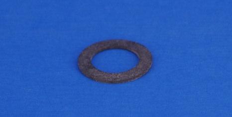
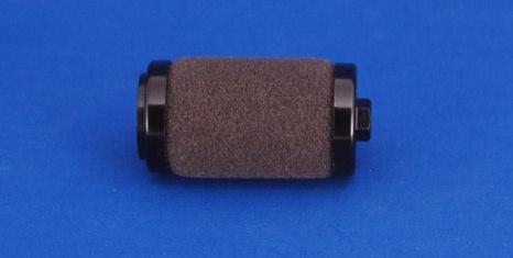
Water Line and Water Line Assembly Gasket
 1 Preparation for Repair 1) Remove tip from scaler 2) Remove scaler from air supply 3) Remove gasket from back end of scaler. Examine gasket for obvious wear or disfigurement. Replace if necessary. 2 Remove
SALES CUSTOMER SERVICE TECHNICAL ASSISTANCE CALL TOLL-FREE:
 DENTAL, INC. TECHNICAL BULLETIN U802-022510 5860 FLYNN CREEK ROAD READ ALL INSTRUCTIONS P.O. BOX 106 BEFORE PROCEEDING COMPTCHE, CALIFORNIA, U.S.A. 95427 SAVE THIS FOR FUTURE REFERENCE THIS PRODUCT IS
CANARY AUDIO. Power Amplifier CA-309 OWNER S MANUAL. Handcrafted in California MADE IN USA
 CANARY AUDIO 300B Push-Pull Parallel Power Amplifier Mono Block Handcrafted in California CA-309 OWNER S MANUAL MADE IN USA Dear Customer: Please allow us to take this opportunity to thank you for purchasing
THIS SHEET CONTAINS IMPORTANT SAFETY INSTRUCTIONS. SAVE THESE INSTRUCTIONS.
 LumeLEX 2026 SERIES INSTALLATION INSTRUCTIONS Important THIS SHEET CONTAINS IMPORTANT SAFETY INSTRUCTIONS. SAVE THESE INSTRUCTIONS. Warning This product must be installed in accordance with National Electrical
The wick in your heater needs replacing if, after repeated cleanings, any of the following conditions still exist:
 WICK REPLACEMENT The wick in your heater needs replacing if, after repeated cleanings, any of the following conditions still exist: Slow to light, hard movement of the wick adjuster knob, kerosene odor
Lumber Smith. Assembly Manual. If you are having problems assembling the saw and need assistance, please contact us at:
 Lumber Smith Assembly Manual If you are having problems assembling the saw and need assistance, please contact us at: 804-577-7398 info@lumbersmith.com 1 Step 1 Safety Carefully read the Owners Manual.
2-1/2" 16 gauge Straight Finish Nailer Includes: 2 Allen wrenches & pneumatic tool oil
 WARRANTY Model 9755 2-1/2" Finish Nailer If you have any problems with this tool, please call FPC Corporation toll-free at 1-800-860-3838 before returning it to the place of purchase. FPC Corporation warrants
STRAIGHT SHAFT TRIMMER ATTACHMENT 29402
 STRAIGHT SHAFT TRIMMER ATTACHMENT 29402 Owner s Manual TOLL-FREE HELPLINE: 1-888-90WORKS (888.909.6757) Read all safety rules and instructions carefully before operating this tool. TABLE OF CONTENTS Introduction...
QB78 CO 2 Pellet Rifle
 QB78 CO 2 Pellet Rifle Maintenance Instructions Text and photos by George Fox Lang The Chinese QB78 pellet rifle is one of the nicest and most popular CO 2 rifles ever produced. Here are the long-wanted
Finger Jointer. Operating and Safety Instructions FJA300
 Finger Jointer FJA300 Operating and Safety Instructions www.tritontools.com Thank you for purchasing this Triton tool. These instructions contain information necessary for safe and effective operation
MUELLER GAS. DH-5/EH-5 Drilling. Reliable Connections. DH-5 Drilling Machine General Information 2. EH-5 Drilling Machine General Information 3
 operating Instructions manual MUELLER GAS TAble of contents PAGE DH-5 Drilling Machine General Information 2 DH-5/EH-5 Drilling EH-5 Drilling Machine General Information 3 Operating Instructions 4-5 DH-5
HIGH VOLUME LOW PRESSURE COMPRESSED AIR SPRAY GUNS
 INSTRUCTION MANUAL (For Professional Use Only) HIGH VOLUME LOW PRESSURE COMPRESSED AIR SPRAY GUNS DO NOT USE SPRAY GUNS BEFORE READING THIS MANUAL 8000 8200 8400 This manual contains important warnings