THE QUEENSLAND STATE VELODROME: FORM AND STRUCTURE THROUGH PARAMETRIC DESIGN
|
|
|
- Moris Morris
- 5 years ago
- Views:
Transcription


1 THE QUEENSLAND STATE VELODROME: FORM AND STRUCTURE THROUGH PARAMETRIC DESIGN
2 01 INTRODUCTION
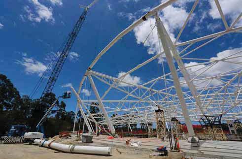
3 01 INTRODUCTION PROJECT OVERVIEW» New indoor 250m timber track velodrome to act as the Queensland state centre and have capability for international UCI events» Large clear spanning indoor stadium» Basic form a response to requirements of natural ventilation, seating strategies and dynamic form inspired by the track geometries USE OF PARAMETRICS THROUGHOUT THE DESIGN STAGES» Conceptual form finding» Conceptual structural modelling» Quantity analysis and design calibration» Analytical definitions for design proof» Detail design development» Construction modelling and shop drawing coordination» Integration of structural detailing with shop models

4


5 LEGACY SEATING VIEW OVERLAY SEATING VIEW

6
7 02 CONCEPTUAL FORM FINDING
 form is generated")

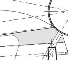
8 02 CONCEPTUAL FORM FINDING ROOF FORM» Hyperbolic Parabola roof (pringle chip) form is generated mathematically from a single centre point. Being a mathematical representation the form remains pure and accurate. [z=ax 2 -by 2 ]


9 02 CONCEPTUAL FORM FINDING ROOF FORM» Control ratios added to adjust the flex of the form in both directions that allowed studies of form generated by the constraints of different cladding materials» These controls also allowed adjustments in the structural solution to raise or lower the extent of catenary arching actions across the span


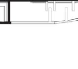
10 02 CONCEPTUAL FORM FINDING WALL FORM» The extent of the wall structure is governed by the shape of the track, which can vary significantly within the UCI standards, and the extent of seating required» Traditional modelling techniques become very inefficient when dealing with a high degree of flex in a complex form
11 02 CONCEPTUAL FORM FINDING WALL FORM» Early forms needed to allow for this flexibility so were controlled by an elliptical plan generation to allow for independent stretching in both axes LEGACY SEATING VIEW OVERLAY SEATING VIEW

12 02 CONCEPTUAL FORM FINDING WALL FORM» Wall pitch needed to be adjustable so the structural span could be fine-tuned over the top of the general building size adjustments.

13 02 CONCEPTUAL FORM FINDING SEATING BOWL» The seating bowl is generated directly from the form of the track to allow sightlines and coordination with the top of the track» The elliptical base form allows easy adjustment to deal with studies affecting the seating form
14 03 CONCEPTUAL STRUCTURAL MODELLING

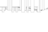
15 03 CONCEPTUAL STRUCTURAL MODELLING ROOF FORMS» A major design issue for large span roofs is the structural concept and generation of a structural diagram that is both efficient and in keeping with the architectural concept.

16 03 CONCEPTUAL STRUCTURAL MODELLING ROOF FORMS» Using the base architectural form definition to generate the structural diagram parametrically provided flexibility in conceptual stages


17 03 CONCEPTUAL STRUCTURAL MODELLING ROOF FORMS» Ability to assess a range of options quickly both structurally and against architectural design intent.» Use of geometry gym to convert centre line to a GSA compatible format to allow for quick analysis
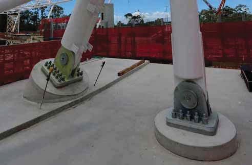
18 03 CONCEPTUAL STRUCTURAL MODELLING ROOF FORMS» A radial truss solution was developed as it kept all angled columns and trusses in plane whilst allowing a perpendicular interface to the cladding form at column lines. Architecturally this structural form could begin to express the form of the building well rather than competing with it.» Structural Engineers were able to set parameters in the definition so that the form could evolve whilst adhering to the basic structural solution.
19 03 CONCEPTUAL STRUCTURAL MODELLING ROOF FORMS» The expected deflection is in the order of 200mm so a precambered steel set out was required to be developed. This required two models to be run simultaneously; this final state for analysis and building coordination, and a pre-cambered state for steel shop drawings. Writing this parametrically allowed a very quick and accurate way to run both and pick up any design development accurately.
20 04 QUANTITY ANALYSIS FOR COST PLANNING
21 04 QUANTITY ANALYSIS FOR COST PLANNING DESIGN CALIBRATION» Through the cost analysis stages a balance has to be struck to deliver the building on cost.» For more complex forms, parametric quantity analysis allows a very quick and flexible method to test many options for impact on building material quantity as well as design intent and effects on building function.» The effects of increasing curvature, wall angle or raising the structure can be hard to predict, but become quickly manageable
22 05 ANALYTICAL DEFINITIONS FOR DESIGN PROOF

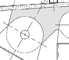
23 05 ANALYTICAL DEFINITIONS FOR DESIGN PROOF» Sight line studies FULL STADIUM SIGHT LINE DIAGRAM GENERATED FROM SCRIPT C VALUE CALCULATION SCRIPT C VALUE DETAIL WEST GRANDSTAND C VALUE RANGES GRADED BY COLOUR


24 05 ANALYTICAL DEFINITIONS FOR DESIGN PROOF» Rainwater flow paths» Roof Curvature ananlysis RAIN WATER PATH ANALYSIS GRAPHIC REPRESENTATION OF CURVATURE


25 05 ANALYTICAL DEFINITIONS FOR DESIGN PROOF» Eaves clash analysis
26 06 DETAILED DESIGN DEVELOPMENT

27 06 DETAILED DESIGN DEVELOPMENT DEVELOPMENT OF THE WALL STRUCTURES» The use of fabric as a cladding material allowed to façade to be developed as a twisted geometry» The wall framing definition used a weave effect projecting alternate nodes to create straight steel lines that induced a warp into the fabric plane» The size of the structural bay is an equal division of the wall creating a compression of the warp as the building curves around the low ends.


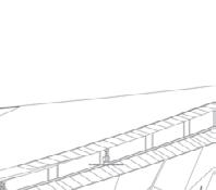
28 06 DETAILED DESIGN DEVELOPMENT DEVELOPMENT OF EAVES STRUCTURES» The development of the eaves form was a complicated process with a number of constraints that needed satisfying» Parametric techniques allowed the design constraints to be built into the definition» The low points required a horizontal plane for coordination of syphonic drains, and the high points were defined by the junction of the louvre head and steel truss lines

29 06 DETAILED DESIGN DEVELOPMENT THREADING THE NEEDLE» A plane for each structural bay needed to be set which combined to maintain the fluid eaves form» The structural constraints only allowed a zone of approx. 200mm through which these planes had to pass in all cases regardless of the pitch in each bay» The planes then needed to be averaged out in a manner that resolved the misalignment in the least visual area» The steel can then be detailed as a flat planar frame making fabrication much easier
30
31 07 CONSTRUCTION MODELLING AND SHOP DRAWING COORDINATION

32 07 CONSTRUCTION MODELLING AND SHOP DRAWING COORDINATION» A structure such as this takes thousands of steel shop drawings and with a complex geometry traditional set out checks in 2D would be extremely laborious.» Traditionally a BIM, when it gets to shop drawing stage has not been of high quality for that purpose and often contains large amounts of superfluous information
33 CONSTRUCTION MODELLING AND SHOP DRAWING COORDINATION» Using raw centre line geometry allows all parties to generate information for base information which has pinpoint accuracy ELD CF419 CF423 CS BS » Minor adjustments can be made to suit steel detailing from this base source CF437 CF428 CF428 CF428 CF427 CF404 CF404 CF438 CF407 BS38 CPBW CF416 CF421 Top View CF437 CF423 CS231 CF413 CF428 CF428 CF428 CS227 CS232 CF CF CF404 CF404 CF435 CF404 C CF404 G 150 SLOT CPBW F 577 MK CUT CUT CF428 CF413 A CS227 CS232 CS238 B CF419 CF404 CF404 C CF SLOT CF435 CF438 BS SLOT BF30 A 18 BS BS18 BF CF437 CF CF CF G B F CS231 A 2114 CF CF (CHECK) B CF427 C CF404 CF407 CF BF3 BF23 BF DETAIL 1278 SLOT 1 16 BF21 BF A BS BS23 SECT. A-A CF A Front View x 12.7 CHS (1 Required) SECT A-A CF428 CS D CF D CS227 CS232 E CS227 CF419 CS238 CF419 SECT. E-E SECT B-B E CF427 CF427 FULL STRENGTH CONTINUOUS FILLET BUTT WELD SECT C-C CS CS238 CF421 CS231 CF TYP 14 CF419 SECT. D-D 6055 SECT. F-F CF SECT. G-G ALL MARKS TO BE PREFIXED BY "C-" EG. C-152A Total Area = 1 Total Mass of all parts = x 50 x 8 UA CS x 6.4 CHS CS x 6.4 CHS CS x 12.7 CHS CS x 12.7 CHS CF PL x CF PL x CF PL x CF PL x CF PL x CF PL x CF PL x CF PL x CF PL x CF PL x CF PL x CF PL x Item Qty Description Length Grade Remarks MATERIAL LIST

34 07 CONSTRUCTION MODELLING AND SHOP DRAWING COORDINATION» Structural model Bentley Prostructures» Full shop model reviews centred around detailing only as base geometry was controlled from base source saving considerable time and maintaining accuracy.

35 REVIT INTERGRATION Combining Steel models for coordination into Revit using updates to be represented in the base drawings
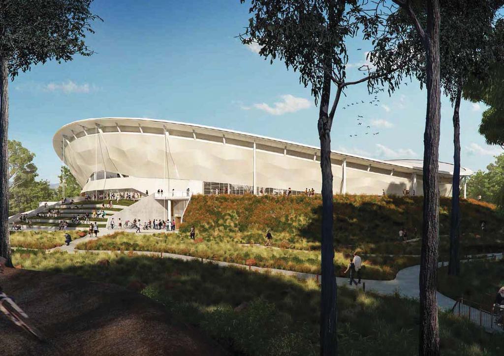
36 08 FINAL IMAGES

37 INTERIOR RENDER


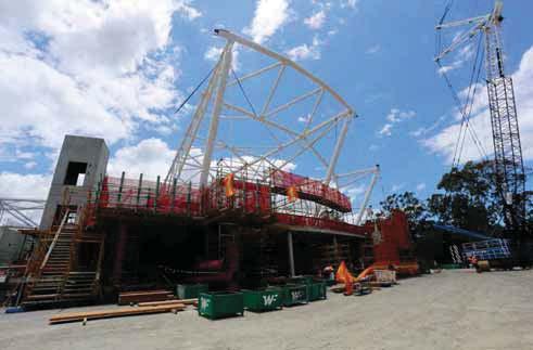
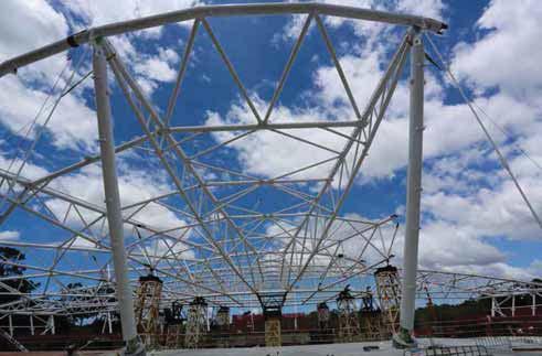
38 FINAL IMAGES

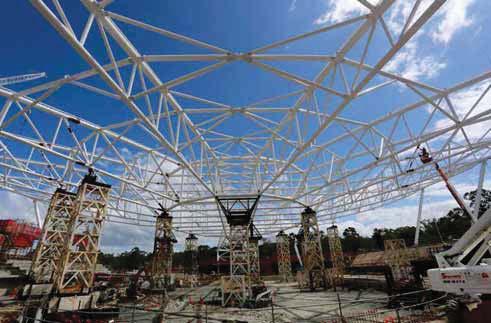
39 FINAL IMAGES
40
A Shell construction
 A Shell construction A 4/2012 Content 1 BASE AND WALL ANCHORING 1.1 Base with mortar bed 1.2 Base with sill plate 1.3 Base with raised sill plate 1.4 Concrete base (mortar bed) 1.5 Concrete base (sill
nineteen Wood Construction 1 and design APPLIED ARCHITECTURAL STRUCTURES: DR. ANNE NICHOLS FALL 2016 lecture STRUCTURAL ANALYSIS AND SYSTEMS ARCH 631
 APPLIED ARCHITECTURAL STRUCTURES: STRUCTURAL ANALYSIS AND SYSTEMS DR. ANNE NICHOLS FALL 2016 lecture nineteen wood construction and design Wood Construction 1 Timber Construction all-wood framing systems
Shingle Installation Guide
 Installation Guide Roof Framing Information Installation Installation Accessory Installation Estimating Data General Information Roof Framing Information It is the responsibility or roofers, building contractors
Glulam Connection Details
 T E C H N I C A L N O T E Glulam Connection Details Note: This version is superseded by a more current edition. Check the current edition for updated design and application recommendations. ENGINEERED
ROOF FRAMING INFORMATION BATTEN INSTALLATION CORONA SHAKE INSTALLATION ACCESSORY INSTALLATION ESTIMATING DATA GENERAL INFORMATION
 ROOF FRAMING INFORMATION BATTEN INSTALLATION CORONA SHAKE INSTALLATION ACCESSORY INSTALLATION ESTIMATING DATA GENERAL INFORMATION ROOF FRAMING INFORMATION It is the responsibility or roofers, building
BRACING BRACING SECTION 7 SECTION 7
 If we are to learn from the past, it is clear that there is generally a lack of understanding of the purpose of roof bracing and who should be responsible for it. This has led to disputes, claims and,
Abstract. 1 Introduction
 Development of a system for computer-aided design of ship hulls M. Ventura*, C.Rodrigues\ C. Guedes Scares* "Unitfor Marine Technology and Engineering, Institute Superior Tecnico, Universidade Tecnica
AS10690 Revit Master Class Building Construction Ready Curtain Walls
 AS10690 Revit Master Class Building Construction Ready Curtain Walls Matt Stachoni BIM Specialist, Microsol Resources Twitter: @MattStachoni Join the conversation #AU2015 Class summary Curtain walls represent
COMPOUND ROOFS WORKSHOP - Introduction Complex roof geometry is a challenge most framers face eventually. These problems can be solved either
 COMPOUND ROOFS WORKSHOP - Introduction Complex roof geometry is a challenge most framers face eventually. These problems can be solved either mathematically or visually, but the complete carpenter will
Sketch technique. Introduction
 Sketch technique Introduction Although we all like to see and admire well crafted illustrations, as a professional designer you will find that these constitute a small percentage of the work you will produce.
Deciphering Weld Symbols - MillerWelds
 Deciphering 91 Weld Shares Symbols When welds are specified on engineering and fabrication drawings, a cryptic set of symbols is used as a sort of shorthand for describing the type of weld, its size, and
Glulam Curved Members. Glulam Design. General Glulam Design. General Glulam Beams are Designed in the SAME Manner as Solid Sawn Beams
 Glulam Curved Members Glulam Design General Glulam Beams are Designed in the SAME Manner as Solid Sawn Beams There is an Additional Adjustment Factor, C v, the Volume Factor C v and C L (Lateral Stability
Storing, Handling, and Cutting Steel Panels
 Storing, Handling, and Cutting Steel s Storing Specifically check your quantities, colors, and lengths All materials should be used as soon as possible Steel bundles should be stored indoors with enough
Fig. 9 Different weld positions. There are five basic types of common joints. They are
 c) Vertical - On the wall d) Horizontal - On the wall Fig. 9 Different weld positions 7.0 TYPES OF JOINTS There are five basic types of common joints. They are Butt joint Lap joint T joint Corner joint,
Advance Steel suite 6.1 / SP2
 Advance Steel suite 6.1 / SP2 This document describes only the improvements in Service Pack 2 compared to Service Pack 1. The installation of SP2 includes SP1; please see the previous document for improvements
Inspire Slate Starter Piece Hip and Ridge. 13 1/2" Height: 13 ½" Width: 12" Squares/ Pallet. Bundles/ Square
 December 2017 Classic Slate Application Guidelines Only Basic Roofing Tools Required Hand fastened or fastened with a pneumatic nail gun Utility knife or a standard circular saw Tape measure, pry bar,
REinVenting an Interior design practice
 Kelvin Tam NBBJ AB2535 Interior designers may think Autodesk Revit software is less useful to them than it is to architects, but this class will definitely change their minds. As the scope of interior
(50 FT FT) MICHIGAN DEPARTMENT OF TRANSPORTATION 10-0" 7-6" 8-0" 6-0" Truss Depth. 3" sheets 5 & 6 of 10) DEPARTMENT DIRECTOR. Kirk T.
 MICHIGAN DEPARTMENT OF TRANSPORTATION 10-0 7-6 8-0 6-0 Truss Depth. 3 sheets 5 & 6 of 10) DEPARTMENT DIRECTOR. Kirk T.") Column truss connection (See details sheets 3 & 4 of 10) \ Span (Odd number of panels) \ Span (Even number of panels) Back truss chord Top truss chord \ Truss Chord splice Truss depth (See details \ Left
Column truss connection (See details sheets 3 & 4 of 10) \ Span (Odd number of panels) \ Span (Even number of panels) Back truss chord Top truss chord \ Truss Chord splice Truss depth (See details \ Left
RAIL PANEL AT TRANSITION SECTION PLAN - POST DETAIL PLAN - TUBE SPLICE. Colorado Department of Transportation. Staff Bridge Branch
 Limits of pay length for Bridge RailType 10M (For post spacing, see Dwg. No. B ) B60610 (Use with B60610A) 8 min. 1 max. 8 min. 1 max. 10 0 Max. 10 0 Max. post spacing 10 0 Max. 2 5 Post 1 x 1 slotted
Honors Drawing/Design for Production (DDP)
") Honors Drawing/Design for Production (DDP) Unit 1: Design Process Time Days: 49 days Lesson 1.1: Introduction to a Design Process (11 days): 1. There are many design processes that guide professionals
Honors Drawing/Design for Production (DDP) Unit 1: Design Process Time Days: 49 days Lesson 1.1: Introduction to a Design Process (11 days): 1. There are many design processes that guide professionals
Creo Parametric 2.0: Introduction to Solid Modeling. Creo Parametric 2.0: Introduction to Solid Modeling
 Creo Parametric 2.0: Introduction to Solid Modeling 1 2 Part 1 Class Files... xiii Chapter 1 Introduction to Creo Parametric... 1-1 1.1 Solid Modeling... 1-4 1.2 Creo Parametric Fundamentals... 1-6 Feature-Based...
Metroll. Purlins & Girts. C Section Purlins. C Section Purlins are manufactured from Galvaspan steel and are roll formed into C Section.
 C Section Purlins C Section Purlins are manufactured from Galvaspan steel and are roll formed into C Section. Metroll C Section Purlins are recommended for simple, non-continuous span construction. Structural
Sun Sculpture. By Scott L. Melnick
 Sun Sculpture By Scott L. Melnick Is it a bridge or a sculpture? The Turtle Bay Sundial Bridge, designed by the worldrenowned Spanish architect/engineer Santiago Calatrava is both. The first steel inclined-pylon,
JUNIOR CERTIFICATE 2009 MARKING SCHEME TECHNICAL GRAPHICS HIGHER LEVEL
 . JUNIOR CERTIFICATE 2009 MARKING SCHEME TECHNICAL GRAPHICS HIGHER LEVEL Sections A and B Section A any ten questions from this section Q1 12 Four diagrams, 3 marks for each correct label. Q2 12 2 marks
Chapter 51: Sidewall Overhang(s) Only - Enclosed
 Only - Enclosed") Chapter 51: Sidewall Overhang(s) Only - Enclosed Most Common Mistakes: 1. Incorrect eave height. 2. Placing eave girt below truss tails. 3. Fascia board top edges not bevel cut to match roof slope. 4.
Chapter 51: Sidewall Overhang(s) Only - Enclosed Most Common Mistakes: 1. Incorrect eave height. 2. Placing eave girt below truss tails. 3. Fascia board top edges not bevel cut to match roof slope. 4.
Design and Technology Resistant materials Key words and definitions
 Design and Technology Resistant materials Key words and definitions Word Acrylic Definition a type of thermoplastic, which is hard and can be transparent. Used to make shop signs. Perspex is a trade/brand
DFTG Blueprint Reading and Sketching
 Course Syllabus DFTG 1325 - Blueprint Reading and Sketching Catalog Description: An introduction to reading and interpreting working drawings for fabrication processes and associated trades. Use of sketching
RHEINZINK - Double Standing Seam
 RHEINZINK - Double Standing Seam Product Overview RHEINZINK - Double Standing Seam Fine seam lines give a slim appearance Harmonises with both traditional and modern architecture Feasible with conical
Heavy Timber Trusses. Workshop: Exposed Connections in Timber Trusses and Structures: Designing for Beauty and Function
 Heavy Timber Trusses Workshop: Exposed Connections in Timber Trusses and Structures: Designing for Beauty and Function Presented by RL. Ben Brungraber, PhD, PE Fire Tower Engineered Timber Disclaimer:
MODELS FOR GEOMETRIC PRODUCT SPECIFICATION
 U.P.B. Sci. Bull., Series D, Vol. 70, No.2, 2008 ISSN 1454-2358 MODELS FOR GEOMETRIC PRODUCT SPECIFICATION Ionel SIMION 1 Lucrarea prezintă câteva modele pentru verificarea asistată a geometriei pieselor,
technical bulletin Roofline Installation Details No.7 Fascia Installation Details Typical Eaves Details K16 Fascia & 9mm Vented Soffit
 Roofline Installation Details This is intended to provide you with a brief overview of the popular products in Kestrel s Roofline range, where they can be used and the main criteria for installation. Typical
Stabalux T. 5.0 Stabalux T 1
 5.0 1 5.1 - System 2 5.1.1 System properties 2 5.1.2 System profiles 6 5.2 - Processing information 9 5.2.1 Mullion-transom joint 9 5.3 - Design 11 5.3.1 System cross sections 11 5.3.2 Notes 13 System
WHY YOU SHOULD USE TUFFLOOR. components
 Tuffloor DESIGN GUIDE WHY YOU SHOULD USE TUFFLOOR Strong and Easily Installed Tuffloor is a steel floor framing system designed for strength and ease of installation, and is an easy and economical alternative
2.3 SPECIFIC DESIGN DHS PURLINS
 2.3 SPECIFIC DESIGN DHS PURLINS 2.3.1 INTRODUCTION Dimond Hi-Span (DHS) Purlin Systems have been designed to comply with AS/NZS 4600:1996, based on physical testing and analysis carried out by the University
In this section, we find equations for straight lines lying in a coordinate plane.
 2.4 Lines Lines In this section, we find equations for straight lines lying in a coordinate plane. The equations will depend on how the line is inclined. So, we begin by discussing the concept of slope.
Design Guide: CNC Machining VERSION 3.4
 Design Guide: CNC Machining VERSION 3.4 CNC GUIDE V3.4 Table of Contents Overview...3 Tolerances...4 General Tolerances...4 Part Tolerances...5 Size Limitations...6 Milling...6 Lathe...6 Material Selection...7
Problem Solving with the Coordinate Plane
 Grade 5 Module 6 Problem Solving with the Coordinate Plane OVERVIEW In this 40-day module, students develop a coordinate system for the first quadrant of the coordinate plane and use it to solve problems.
General Layout. Eng. Maha Moddather
 General Layout Eng. Maha Moddather mahamoddather@eng.cu.edu.eg Introduction Concrete Beam subjected to Bending Moment around Major Axis M x Compression d Concrete tensile strength is neglected A S Tension
50948-RHN Putney. 06 January This document includes: Aluminium strip/ sheet coverings/ flashings 1. Code Section Revision Dated
 50948-RHN Putney 06 January 2018 This document includes: Code Section Revision Dated H72 Aluminium strip/ sheet coverings/ flashings 1 Table of Contents Title H72 Aluminium strip/ sheet coverings/ flashings
TECHNICAL BULLETIN 28
 November 2015 TECHNICAL BULLETIN 28 INCLINED PREFORMED GRP VALLEY TROUGHS 1. BACKGROUND 1.1 Preformed GRP (Glass Reinforced Polyester) Valley Troughs have been used successfully in the roofing industry
eb^sv=qfj_bo UNIVERSITY OF WISCONSIN - STOUT COLLEGE OF SCIENCE TECHNOLOGY ENGINEERING & MATHEMATICS Architectural Technology AEC 233
 eb^sv=qfj_bo UNIVERSITY OF WISCONSIN - STOUT COLLEGE OF SCIENCE TECHNOLOGY ENGINEERING & MATHEMATICS Architectural Technology AEC 233 Dr. Jason E. Charalambides fkqolar`qflk Heavy timber construction consists
CCFSS Technical Bulletin
 CCFSS Technical Bulletin Vol. 12, No. 1 February 2003 FREQUENTLY ASKED QUESTIONS CONCERNING THE AISI BASE TEST METHOD AND THE USE OF THE AISI ANCHORAGE EQUATIONS Answers Provided by the AISI Task Committee
Descriptive Geometry CH17 : DEVELOPMENTS
 Descriptive Geometry CH17 : DEVELOPMENTS Developments A development is a flat representation or pattern that when folded together creates a 3D object. Developable Surfaces A developable surface may be
Info Sheet PowerSTAIRS Software
 Info Sheet PowerSTAIRS Software Picture 1 POWERSTAIRS is the ideal CAD for the design of complete stairs or single pieces. With the aid of POWERSTAIRS realizing a staircase is really within everybody s
Skewed connections result when members frame to each
 Design of Skewed Connections LARRY KLOIBER and WILLIAM THORNTON ABSTRACT Skewed connections result when members frame to each other at an angle other than 90º. This paper provides some guidance in the
GL5: Visualisation and reading drawings
 436-105 Engineering Communications GL5:1 GL5: Visualisation and reading drawings Being able to both: represent a 3D object in multiview drawings interpret a multiview drawing to visualise a 3D object is
RPMSP Series Installation Guide
 RPMSP Series Installation Guide Contents 1. Overview... page 1 2. Unpacking the Projector...2 3. Projector Configuration...2 4. Projector Throw Distance and Mounting...9 5. Projection Lens Focus...9 6.
JAZZ DESIGNS. Looking for a designer that understands you and your market? B U I L D I N G D E S I G N E R S
 RESIDENTIAL DESIGN COMMERCIAL DESIGN URBAN DESIGN INTERIOR DESIGN JAZZ DESIGNS IS A PROGRESSIVE AND INNOVATIVE BUILDING DESIGN FIRM THAT IS COMMITTED TO PROVIDING ITS CLIENTS WITH A HIGH STANDARD OF BUILD
Architecture 2012 Fundamentals
 Autodesk Revit Architecture 2012 Fundamentals Supplemental Files SDC PUBLICATIONS Schroff Development Corporation Better Textbooks. Lower Prices. www.sdcpublications.com Tutorial files on enclosed CD Visit
JUNIOR CERTIFICATE 2008 MARKING SCHEME TECHNICAL GRAPHICS HIGHER LEVEL
 JUNIOR CERTIFICATE 2008 MARKING SCHEME TECHNICAL GRAPHICS HIGHER LEVEL Sections A and B Section A - any ten questions from this Section Q1 12 Four diagrams, 3 marks for each correct label. Q2 12 3 height
Inspire Aledora Slate Application Guidelines
 July 2014 Inspire Aledora Slate Application Guidelines Only Basic Roofing Tools Required Hand fastened or fastened with a pneumatic nail gun Utility knife or a standard circular saw Tape measure, pry bar,
National BIM Standard - United States Version 3
 National BIM Standard - United States Version 3 5 Practice Documents 5.5 Mechanical, Electrical, Plumbing, And Fire Protection Systems (MEP) Spatial Coordination Requirements for Construction Installation
MN Modelling Objects and Creating Manufacturing Strategy
 Abstract This document and the accompanying files describe the process of modelling a bell housing jig using the 3D software Catia V5. The manufacturing process by which the bell housing would be created
Chapter 16: Roof Steel
 Chapter 16: Roof Steel Most Common Mistakes: 1. Roof purlins not checked for alignment. 2. Failure to properly square roof. 3. Reversing steel laps. 4. Using not enough or too many screws. 5. Over or under
British Columbia Carpenter Apprenticeship Program
 British Columbia Carpenter Apprenticeship Program Level 3 Line H Competency H-7 Build Intersecting Roofs 7960003573 Ordering Crown Publications, Queen s Printer PO Box 9452 Stn Prov Govt 563 Superior St.
Advance Steel 2010 / SP2
 Advance Steel 2010 / SP2 This document describes the improvements in Service Pack 2 for Advance Steel 2010. Advance Steel 2010 SP2 is Windows 7 compliant! BOM/LISTS New sorting option in Drawing index
LUX INSTALLATION GUIDE. LUX Panel V Groove Installation. Installation Guide. February
 LUX Panel V Groove Installation Installation Guide February 2017 www.luxpanel.ca LUX Panel V Groove Installation LUX panel steel cladding is designed to be installed vertically, horizontally, diagonally
Multiviews and Auxiliary Views
 Multiviews and Auxiliary Views Multiviews and Auxiliary Views Objectives Explain orthographic and multiview projection. Identifying the six principal views. Apply standard line practices to multiviews
C.2 Equations and Graphs of Conic Sections
 0 section C C. Equations and Graphs of Conic Sections In this section, we give an overview of the main properties of the curves called conic sections. Geometrically, these curves can be defined as intersections
CND INCORPORATED Massillon, OH
 Report on Vibratory Stress Relief Prepared by Bruce B. Klauba Product Group Manager CND INCORPORATED Massillon, OH 9500 HP FAN HOUSINGS Large distortion during separation of 9500 HP Fan Housing halves
BIM/VDC on TAA Projects:
 2018 Logan International Airport BIM/VDC on TAA Projects: Direct Tenant TAA Projects Third Party Development Properties Massachusetts Port Authority Capital Programs & Environmental Affairs Preface Massport
TYPE J (20 FT - 40 FT) MICHIGAN DEPARTMENT OF TRANSPORTATION 10-0" 7-6" NOTE: sheet 5 & 6 of 10) DEPARTMENT DIRECTOR. Kirk T.
 MICHIGAN DEPARTMENT OF TRANSPORTATION 10-0 7-6 NOTE: sheet 5 & 6 of 10) DEPARTMENT DIRECTOR. Kirk T.") Column truss connection Chord splice (see details (See details sheets 3 & 4 of 10) s Top truss chord Free end panel 10-0" Support end panels length varies (See chart below) \ Truss Back truss chord Top
Column truss connection Chord splice (see details (See details sheets 3 & 4 of 10) s Top truss chord Free end panel 10-0" Support end panels length varies (See chart below) \ Truss Back truss chord Top
Installation Guide Simplicity Alfresco. V1.9 Lu070318
 0333 305 5272 www.canoports.co.uk Installation Guide Simplicity Alfresco V1.9 Lu070318 Tools Required Below is a list of tools that you will require to install your the Simplicity Alfresco System. Cordless
Steeline X-SPAN purlins
 Steeline X-SPAN purlins DESIGN MANUAL F y y L R5 t D 2 Origin x x x x y D L steeline.com.au y y E CONTENTS IMPORTANT NOTES... 1-1 DISCLAIMER... 1-1 INTRODUCTION... 1-2 HOW TO USE THE X-SPAN purlins DESIGN
Parametric Strategies in Civic Architecture Design
 Parametric Strategies in Civic Architecture Design Nathan Miller NBBJ Figure 1 Aerial view of the Kintex Exposition Center Phase II Abstract Using several NBBJ civic projects as case studies, this paper
Rigid Connections. Between Wood posts and concrete
 Research + Technology Research + Technology Rigid Connections Between Wood posts and concrete By David R. Bohnhoff, PHD, PE Modeling Connections The primary goal of a structural engineer is to ensure that
Special Roofs and Vertical Slating
 Special Roofs and Vertical Slating Roofs falling into the category of "special" roofs have the following characteristics: (a) any roof slope equal to or greater than the minimum pitch for the size of slate
HILAND TRAY FORM AND FUNCTION MATERIAL SPECIFICATIONS DESIGN GUIDE ROOFING I WALLING
 HILAND TRAY ROOFING I WALLING DESIGN GUIDE FORM AND FUNCTION Hiland Tray is a modern 455mm wide tray roofing and walling system, roll formed onsite with a mobile roll forming facility in long single lengths
Introduction to CATIA V5
 Introduction to CATIA V5 Release 17 (A Hands-On Tutorial Approach) Kirstie Plantenberg University of Detroit Mercy SDC PUBLICATIONS Schroff Development Corporation www.schroff.com Better Textbooks. Lower
M TE S Y S LT U A S S A
 Dress-Up Features In this lesson you will learn how to place dress-up features on parts. Lesson Contents: Case Study: Timing Chain Cover Design Intent Stages in the Process Apply a Draft Create a Stiffener
technical bulletin Roofline Installation Details No.7 Fascia Installation Details Typical Eaves Details K16 Fascia & 9mm Vented Soffit
 Roofline Installation Details This is intended to provide you with a brief overview of the popular products in Kestrel s Roofline range, where they can be used and the main criteria for installation. Typical
1. Enumerate the most commonly used engineering materials and state some important properties and their engineering applications.
 Code No: R05310305 Set No. 1 III B.Tech I Semester Regular Examinations, November 2008 DESIGN OF MACHINE MEMBERS-I ( Common to Mechanical Engineering and Production Engineering) Time: 3 hours Max Marks:
2003 Academic Challenge
 Worldwide Youth in Science and Engineering 2003 Academic Challenge ENGINEERING GRAPHICS TEST - REGIONAL Engineering Graphics Test Production Team Ryan Brown, Illinois State University Author/Team Coordinator
Z and C - sections ZED PURLIN SYSTEMS. Design tables according to Eurocodes. For secondary steel structures. Large range of. Z and C - sections
 ZED PURLIN SYSTEMS Large range of Z and C - sections System solution Purlins and side rails Eaves beams Floor beams Framing Easy design in software MetSPEC 12 Z and C - sections For secondary steel structures
TEACHING PARAMETRIC DESIGN IN ARCHITECTURE
 TEACHING PARAMETRIC DESIGN IN ARCHITECTURE A Case Study SAMER R. WANNAN Birzeit University, Ramallah, Palestine. samer.wannan@gmail.com, swannan@birzeit.edu Abstract. The increasing technological advancements
I. Architectural drawings. Pod 4x3 LTH (34)
") I. Architectural drawings Pod 4x3 LTH (34) 1 I.1. Building plan: 2 II. Assembly guide step by step 1. STEP (tools & care) To assemble the building you will need the following tools: 3 2. STEP Before erecting
I. Architectural drawings Pod 4x3 LTH (34) 1 I.1. Building plan: 2 II. Assembly guide step by step 1. STEP (tools & care) To assemble the building you will need the following tools: 3 2. STEP Before erecting
Straight Bevel Gears on Phoenix Machines Using Coniflex Tools
 Straight Bevel Gears on Phoenix Machines Using Coniflex Tools Dr. Hermann J. Stadtfeld Vice President Bevel Gear Technology January 2007 The Gleason Works 1000 University Avenue P.O. Box 22970 Rochester,
BIM & Emerging Technologies. Disrupting Design process & Construction
 BIM & Emerging Technologies Disrupting Design process & Construction Introduction Introduction - BIM Disrupting the Construction Introduction Design Major disruption already in various parts of the World
SECTION PROJECT COORDINATION VIA BIM
 SECTION 01 31 13 PROJECT COORDINATION VIA BIM PART 1 - GENERAL 1.1 RELATED DOCUMENTS A. Drawings and general provisions of the Contract, including General and Supplementary Conditions and other Division
HBS-AP ASSEMBLING INSTRUCTIONS
 ALUMINIUM PIPEWORK - ALUMINIUM PIPEWORK - ALUMINIUM PIPEWORK 97 HBS-AP ASSEMBLING INSTRUCTIONS 1. INTRODUCTION 1.1. This manual is very easy to consult and we recommend reading it before starting work,
-SQA-SCOTTISH QUALIFICATIONS AUTHORITY. Hanover House 24 Douglas Street GLASGOW G2 7NG NATIONAL CERTIFICATE MODULE DESCRIPTOR
 -SQA-SCOTTISH QUALIFICATIONS AUTHORITY Hanover House 24 Douglas Street GLASGOW G2 7NG NATIONAL CERTIFICATE MODULE DESCRIPTOR -Module Number- 0065213 -Session-1986-87 -Superclass- -Title- TM STRUCTURAL
LANDMARK UNIVERSITY, OMU-ARAN
 LANDMARK UNIVERSITY, OMU-ARAN LECTURE NOTE: DRILLING. COLLEGE: COLLEGE OF SCIENCE AND ENGINEERING DEPARTMENT: MECHANICAL ENGINEERING PROGRAMME: MECHANICAL ENGINEERING ENGR. ALIYU, S.J Course code: MCE
TEPZZ 7545 A_T EP A1 (19) (11) EP A1 (12) EUROPEAN PATENT APPLICATION. (43) Date of publication: Bulletin 2014/29
 (11) EP A1 (12) EUROPEAN PATENT APPLICATION. (43) Date of publication: Bulletin 2014/29") (19) TEPZZ 74 A_T (11) EP 2 74 11 A1 (12) EUROPEAN PATENT APPLICATION (43) Date of publication: 16.07.14 Bulletin 14/29 (21) Application number: 1476.7 (1) Int Cl.: B21F 27/ (06.01) B21C 1/02 (06.01) C21D
(19) TEPZZ 74 A_T (11) EP 2 74 11 A1 (12) EUROPEAN PATENT APPLICATION (43) Date of publication: 16.07.14 Bulletin 14/29 (21) Application number: 1476.7 (1) Int Cl.: B21F 27/ (06.01) B21C 1/02 (06.01) C21D
Computer Aided Design I
 Black Horse Pike Regional School District 580 Erial Road, Blackwood, NJ 08012 Computer Aided Design I COURSE OF STUDY Technology Department Written by: Ken Whalen, Steve Arena and Vince Mannino Date: May
Certificate of Appropriateness (CoA) Checklist
 Checklist") Certificate of Appropriateness (CoA) Checklist This Checklist is intended to assist you in preparing a complete application for submittal. Occasionally, additional items may be required to complete the
Certificate of Appropriateness (CoA) Checklist This Checklist is intended to assist you in preparing a complete application for submittal. Occasionally, additional items may be required to complete the
Discuss your project with a Locker Group Architectural Consultant at the outset, to ensure you achieve the best results.
 Technical Data Sheet PIC PERF SPECIFICATION Sheet No: LP-105.3 April 2011 Pic Perf is a digitally created image produced in Perforated Metal. Pic Perf is available in a wide variety of specifications,
Discover how to draw a picture that looks distorted on the page, but normal in a cylindrical mirror.
 6 th 12 th grade Asking questions Planning and carrying out investigations Using mathematics and computational thinking Constructing explanations and designing solutions 45 minutes Empty soda can 8.5"
Laser Trackers for Production of Automotive Tooling
 Case Study Laser Trackers for Production of Automotive Tooling PICO EUROPE designs, manufactures, installs and commissions automotive production lines worldwide for many automotive manufacturers including
EZ TUBE 6FT CURVED TABLETOP
 EZT6CRVTTG1 (Single) EZT6CRVTTG2 (Double) EZ TUBE 6FT CURVED TABLETOP The fabric stretches over the frame to create a seamless and eye Display Size 72 W x 60 H x 10 D Graphic Print - 74 W x 59.5 H Single
AutoCAD Civil 3D 2009 ESSENTIALS
 AutoCAD Civil 3D 2009 ESSENTIALS SDC PUBLICATIONS Schroff Development Corporation www.schroff.com Better Textbooks. Lower Prices. Alignments and Profiles Section 2: Profiles In this section you learn how
FORWARD FUSELAGE SIDES & REAR TOP SKINS
 FORWARD FUSELAGE SIDES & REAR TOP SKINS WORK REPORT Step No. Check Parts / Tools Qty Preparations. 1 [ ] 6F5-3 Upper Front Longerons 2 2 [ ] 6F5-5 Heel Support 1 3 [ ] 6F5-2 Front Floor Skin 1 3 [ ] Firewall
Chapter 1: DC circuit basics
 Chapter 1: DC circuit basics Overview Electrical circuit design depends first and foremost on understanding the basic quantities used for describing electricity: Voltage, current, and power. In the simplest
Sutton Screened in Awning / Porch
 Sutton Screened in Awning / Porch Sections: Project Overview Roof Work Cedar Framing Canopy Frame Screen Frames Misc. Sheet 1 - - - Index Sheet 2 - - - Project Summary Sheet 3 - - - Roof Work overview
2010 Academic Challenge
 2010 Academic Challenge ENGINEERING GRAPHICS TEST STATE FINALS This Test Consists of 40 Questions Engineering Graphics Test Production Team Ryan K. Brown, Illinois State University Author/Team Leader Jacob
TEST SERIES TO EVALUATE THE STRUCTURAL BEHAVIOUR OF ISOBOARD OVER RAFTER SYSTEM
 TEST SERIES TO EVALUATE THE STRUCTURAL BEHAVIOUR OF ISOBOARD OVER RAFTER SYSTEM J A Wium Institute of Structural Engineering 19 November 2007 ISI2007-3 TEST SERIES TO EVALUATE THE STRUCTURAL BEHAVIOUR
Autodesk Revit Architecture 2014
 ISI ACADEMY Autodesk Revit Architecture 2014 Getting Started Starting Revit Starting Revit for the First Time Opening a Project File Identifying the User Interface Managing User Interface Understanding
Nutec Bigsix Roofing Accessories
 Nutec Bigsix Roofing Accessories Nutec Bigsix Close Fitting Adjustable Ridge Capping (Grey) Adjustable for 0º - 0º pitches 70-000 87 mm 70-00 87 mm Nutec Bigsix Close Fitting Adjustable Ridge Capping (Terracotta)
Development of Automated Stitching Technology for Molded Decorative Instrument
 New technologies Development of Automated Stitching Technology for Molded Decorative Instrument Panel Skin Masaharu Nagatsuka* Akira Saito** Abstract Demand for the instrument panel with stitch decoration
Representation of features Geometric tolerances. Prof Ahmed Kovacevic
 ME 1110 Engineering Practice 1 Engineering Drawing and Design - Lecture 6 Representation of features Geometric tolerances Prof Ahmed Kovacevic School of Engineering and Mathematical Sciences Room C130,
Sheet Metal OverviewChapter1:
 Sheet Metal OverviewChapter1: Chapter 1 This chapter describes the terminology, design methods, and fundamental tools used in the design of sheet metal parts. Building upon these foundational elements