gmodeller : User Guide
|
|
|
- Wendy Grant
- 5 years ago
- Views:
Transcription


1 gmodeller : User Guide
2 CONTENTS 1. gmodeller HOW TO MODEL YOUR BUILDING 1.1. Introduction 1.2. Level of detail required 1.3. Revising Floor Plans Simplifying Zoning D CAD imports D Model generation Extruding Surfaces Components Window & Door Openings 2. INTRODUCTION TO gmodeller 3. GETTING STARTED 3.1. Downloading gmodeller Switching off gmodeller plug in 3.2. Greenspace Live Interface gmodeller icon genergyepc gworkspace gdashboard 3.3. Modeller Interface General Location Summary Surface Details Energy Analysis 3.4. Toolbar Greenspace icon 4. SECTION PLANE TOOL 5. ASSIGNING SURFACES AND OPENINGS 6. ASSIGNING SPACES 6.1. Select Space 6.2. Create Space 6.3. Moving Section Plane 7. EXPORTING/IMPORTING YOUR gbxml 7.1. How to export your gbxml 7.2. Importing a gbxml file


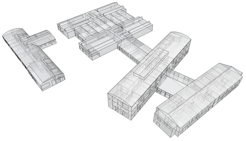
3 1. gmodeller How to model you building 1.1. Introduction This guide will take you through the process of modelling your building in Google Sketch Up for the purposes of gmodeller. There are various methods that a Sketch Up user may adopt when generating their model but this guide will cover a step by step process to follow and highlight best practices when modelling for gmodeller purposes. The process and methods described in the guide are also best practice for minimising the risk of creating mistakes and potential problems which you may encounter when modelling your building Level of detail required It is very important to understand the level of detail required when modelling your building for the purposes of gmodeller. Shown below is a typical detailed building created using Google sketch up. A building model of this level of detail is not suitable for gmodeller. A much simpler, less time consuming model is required to give an appropriate gbxml representation of your building. Below is the same building as before but with the level of detail required for generating a gbxml of your building using gmodeller. The reason for this simplified building model is that gmodeller only requires a single face whether it is a wall, floor, roof etc for applying building information to.

4 1.3. Revising Floor Plans Simplifying The first task is to simplify your building plans. The fabric of your building will be made up of single surfaces meaning that walls, floors etc depths will not be modelled therefore you are required to simplify your floor plans taking the centrelines of all internal walls and the inside line of all external walls in order to achieve as accurate zone areas and volumes as possible as shown below Zoning It is important to minimise the number of surfaces and zones your building.

5 It is advisable that you merge adjacent zones if they are of the same activity/use. This is particularly important when modelling larger buildings in order to speed up the modelling and energy analysis process while minimising file size and data input D CAD imports Google Sketch Up Pro allows you to import dwg or dxf files which can be generated with software such as AutoCAD from Autodesk meaning you can save modelling time by importing existing 2D drawings which can be exploded and used to model your building or used as a guide. The free version of Google Sketch Up does not have this capability but there is a plug in you can download from Google which allows you to import dwg/dxf files D Model generation Extruding Surfaces Once you have your revised floor plans you are then ready to begin creating your 3D building model. The building envelope can be modelled in a variety of ways depending on the preference of the user i.e. by extruding the multiple faces created by the floor plan or by using the floor plan and drawing the different planes through use of line tools. We recommend that you select the Sketch Up extrude tool, click on the surface you wish to extrude and press ctrl and repeat the process for all surfaces on your floor plan. The reason for pressing control on extrusion is that it will also create the internal walls of your model, if you don t press control when extruding the surfaces then the internal walls will not be created as shown below.


6 Another reason we advise you to model your building this way is that it is the best method for ensuring that no gaps occur between faces which may occur if you are drawing all walls manually. It is also the quickest method of generating your building model Components For more complex buildings particularly, you may decide to make your building model using the Sketch Up grouping or component tool. These tools are very useful for managing and modifying your building model, however, the gmodeller does work with components or groups therefore you must explode all components and groups prior to using the gmodeller plug in. If you do use components or groups when making your building model then care must be taken when exploding your model. Ensure that the components are aligned correctly to avoid gaps or any other deficiencies that may result when exploding Window & Door Openings A potential pitfall when generating your building model is when you begin to draw openings onto the external faces of your model. You must ensure that the opening is drawn directly onto the parent face otherwise an opening will not be applied when you begin to apply surfaces using gmodeller. Particular care should be taken when drawing openings on surfaces that don t run parallel to the green or red axis.

7 2. INTRODUCTION TO gmodeller gmodeller allows you to export and import gbxml files in Google SketchUp. Create your building model in Google SketchUp following the gmodeller guidelines in the help guide. Apply surfaces to your model using the gmodeller surfaces and openings palettes in Sketch Ups paint bucket tool. Identify spaces in your building model using the gmodeller select space and create space tools. Once you have assigned all your surfaces and identified all your spaces you are then ready to export a gbxml of your building Model.
8 3. GETTING STARTED 3.1. Downloading gmodeller It is advisable that you download Google Sketch Up ( prior to downloading the gmodeller plug-in ( from Greenspace Live. Having downloaded the gmodeller plug-in, the gmodeller toolbar and Greenspace Live interface should be visible every time you open Google Sketch Up once gmodeller has been installed Switching off gmodeller plug in If for any reason you require to switch off the gmodeller plug, on the Google Sketch Up menu bar go to Window, Preferences, Extensions and simply un-tick the GreenspaceLive gmodeller box from the Extensions list. You will then be required to close and re-open Google Sketch Up for the plug in to be switched off Greenspace Live Interface Once you have downloaded and installed gmodeller the Greenspace Live Interface will appear every time you open Google Sketch Up. The interface displays 4 large icons each related to a different tool in the Greenspace Live toolset. By clicking on an icon the interface will then display data in your Greenspace Live account in relation to the tool selected, therefore, for gmodeller information click on the gmodeller to display the gmodeller interface gmodeller icon When working in Google SketchUp, if you click on the gmodeller icon on the greenspacelive interface start page, the gmodeller interface will appear and displays the gbxml information that you have assigned to your Sketch Up model using gmodeller including General, Location, Summary, Surface Details and GBS Run data.


9 genergyepc The genergyepc icon when working in Google SketchUp displays all your portfolios/files from gworkspace and by selecting a portfolio/file it displays all your gbxml files for the selected portfolio/file gworkspace By clicking on the gworkspace icon all your gbxml and Sketch Up files in each gworkspace project will be displayed when working in Google SketchUp.


10 gdashboard By selecting the gdashboard icon you will be able to view your energy analysis runs for all you buildings in each of your projects that you generated in genergyepc Modeller Interface The gmodeller interface will display information related to the building model you are working on at that present time in Google Sketch Up. If you are working within another tool from Greenspace Live by clicking on the gmodeller link, all Sketch Up files will be accessible through their associated portfolio or project file.


11 General The General tab on the gmodeller interface is used for entering Building Information regarding your building model including name and description. The information under this tab is not required for genergyepc but the information may be required for other energy analysis software Location Like the General tab the Location tab data is only required if your intentions are for software other than gepc. This section requires you to fill in the location data regarding you building model. It is advisable that you use Google Sketch Up s own Location entry (Window, Model Info, Location) and Google earth to determine the exact Location and orientation of your building model.

12 Summary The Summary tab is an important section in the gmodeller interface. The Summary tab records all the types of surfaces and openings along with the spaces that you are adding to your building model and it is recommended that you have this tab displayed when you are adding surfaces, openings and spaces to your model to ensure that they are being recorded correctly Surface Details Like the Summary tab, the Surface Details tab is important when adding your surfaces, openings and spaces to your model. If you make a mistake during the populating process you can rectify the mistake by locating the incorrect surface or space added to your building model from the associated list and deleting. To allow you to easily locate when searching for a surface, opening or space in your model, by selecting one from the list, that surface, opening or space will become highlighted in your model. You can also use this section to track the spaces you are adding to your model to ensure you have added all the spaces in your building or that you have not added the same space twice Energy Analysis From here you can export a gbxml representation of your building model by clicking on the Export gbxml button or create a direct run to Autodesk s Green Building Studio (GBS).


13 This GBS Run is only applicable to users who have a GBS account as you are required to log into your GBS account through the gmodeller interface in order to create a direct run Toolbar The gmodeller toolbar will automatically appear in Google SketchUp once you have downloaded and installed the gmodeller plug in Greenspace icon The Greenspace icon opens the gmodeller interface if closed or reverts back to the Greenspace Live toolset start page if you have navigated away from it. To open the gmodeller interface from the start page simply click on the gmodeller icon.
14 The Export gbxml tool exports a gbxml representation of your building model once you have applied ally your gmodeller surfaces, openings and spaces to your model. The Import gbxml tool allows you to import a gbxml into Google SketchUp. This gbxml import functionality is not limited to gbxml s generated in SketchUp using gmodeller. It can import gbxml s generated with any other modelling tool such as Revit or ArchiCAD. The Select Space tool is an automatic space selection tool you can use when adding spaces to your model. This will save you from having to select each surface of the desired space manually. If the select space tool fails to recognise all the surfaces of your space a warning will appear and you can add missing surfaces by holding control and selecting the surface using SketchUp s select tool. The select space may sometimes select a surface outside the desired space so ensure that you have checked that the space has been identified correctly before creating the space; select space manually if the select space fails to recognise boundaries of the desired space. The create Space tool is selected when a space has been highlighted manually or by using the select space tool successfully and records the space in the gmodeller interface. You will be asked to name the space before the space is recorded in the gmodeller interface. The Move Plane tool allows you to move a section plane when adding spaces to your model without distorting the model which would result from trying to move the section plane using SketchUp s own move tool. The Create Plane tool is a one of Google SketchUp s tools which allow you to view the internal areas of your building model. It is located on the gmodeller toolbar for convenience sake as it will be required when you start adding spaces to your model.

15 4. Section Plane Tool An essential tool when using the gmodeller plug in is Google Sketch Ups own section plane tool which is found on the menu bar under Tools, Section Plane or by clicking on the section plane icon on the gmodeller toolbar. Once you have made your building model you can use the section plane tool to view internal elements and allows you to easily add surfaces, openings and spaces to the internal faces of your building model. The section plane can be deleted using Sketch Ups select tool and clicking on the section plane and pressing delete on your keyboard. The gmodeller move plane tool allows you to move the section plane without distorting the building model when you are in the middle of identifying a space in your building model which would occur if you tried to move the section plane with Google Sketch Ups own move tool.


16 5. Assigning Surfaces and Openings The first task involved in generating your gbxml using gmodeller is to assign surfaces and openings to it. This means telling the gmodeller where the walls, floors, windows etc are in your model and this is done using Google Sketch Ups own paint tool. When you download and install gmodeller two new folders are automatically added to the paint tools materials palette. The folders are named gmodeller surfaces and gmodeller openings and each contain a variety of surface types to be applied to your model using the paint bucket tool. To apply the surfaces select the paint bucket tool and select your desired surface material and click on the surface of your model you wish to assign that surface type to.


17 If assigned correctly the surface of your model will change to the colour of the associated material selected and under the summary tab on the gmodeller interface an extra surface or opening will be added to the associated surface type. It is recommended that you apply gmodeller surfaces prior to adding gmodeller openings and it is also recommended that you assign all openings to their parent surface prior to saving and closing your building model to ensure that gmodeller recognises an opening in a surface i.e. if you add an external wall surface which has an opening, ensure you apply a gmodeller opening surface to that opening prior to closing and/or saving your model. 6. Adding spaces to your building model Having assigned all your surfaces and openings to your model, the next task is to add spaces to the model Select Space The select space tool enables you to quickly select an individual space in your building model. It automatically detects all the surfaces of a space when you double click on the floor surface of that space, saving you from having to select every individual surface of the space manually. However, this automatic space selection tool does not always detect every surface of the space and a warning may appear on your screen if this is the case telling you that the selected space is not enclosed. To include the missing surfaces of the space, hold ctrl and use the select tool to add the missing surfaces to the space you wish to create. Another reason this warning may appear is that
18 there could be a gap between two surfaces and to avoid this care must be taken when building your model and by examining spaces prior to assigning surface, openings and spaces to your model Create Space Having selected your space, save the space by clicking on the create space icon. Once you ve clicked on the create space icon you will be asked to name the space. To ensure that the space has been added, select the summary tab on the gmodeller interface and the space should be listed along with any other spaces you have added to your building model Moving Section Plane The gmodeller move plane tool is an essential tool for when you are identifying spaces in your building model. It allows you to move the section plane without distorting the building model when you are in the middle of identifying a space in your building model which would occur if you tried to move the section plane with Google Sketch Ups own move tool. 7. Exporting/Importing your gbxml 7.1. How to export your gbxml Once you have applied all your surfaces, openings and spaces to your building model you are ready to export your gbxml. This can be done via the menu bar, Plugins, gmodeller, Export gbxml. You will then be required to name and save your gbxml Importing a gbxml file You can import a gbxml file into Google Sketch Up by going to Plugins on the menu bar, gmodeller, and selecting Import gbxml.
EG1003 Help and How To s: Revit Tutorial
 EG1003 Help and How To s: Revit Tutorial Completion of this tutorial is required for Milestone 1. Include screenshots of it in your Milestone 1 presentation. Downloading Revit: Before beginning the tutorial,
UNIT 11: Revolved and Extruded Shapes
 UNIT 11: Revolved and Extruded Shapes In addition to basic geometric shapes and importing of three-dimensional STL files, SOLIDCast allows you to create three-dimensional shapes that are formed by revolving
Google SketchUp TECHNICAL WORKSHOPS
 TECHNICAL WORKSHOPS Outcomes: -A reasonable technical understanding of OS referencing for accurately aligning contours to OS Cad bases -A general understanding of SkecthUp add-ons and their implications/
Autodesk Revit : Burning CDs That Even Your Contractor Can Use
 December 2-5, 2003 MGM Grand Hotel Las Vegas Autodesk Revit : Burning CDs That Even Your Contractor Can Use Speaker: Assistants: Paul Francis Loreto, AAC, OAA, MRAIC Clyne Curtis Peter Funk Course ID:
CAD Tutorial 24: Step by Step Guide
 CAD TUTORIAL 24: Step by step CAD Tutorial 24: Step by Step Guide Level of Difficulty Time Approximately 40 50 minutes Lesson Objectives To understand the basic tools used in SketchUp. To understand the
House Design Tutorial
 House Design Tutorial This House Design Tutorial shows you how to get started on a design project. The tutorials that follow continue with the same plan. When you are finished, you will have created a
House Design Tutorial
 House Design Tutorial This House Design Tutorial shows you how to get started on a design project. The tutorials that follow continue with the same plan. When you are finished, you will have created a
When you complete this assignment you will:
 Objjectiives When you complete this assignment you will: 1. Set-up menus and drawing for designing modeling problems. 2. become familiar with the Sketch menu tools and commands. 3. Produce a three-dimensional
House Design Tutorial
 Chapter 2: House Design Tutorial This House Design Tutorial shows you how to get started on a design project. The tutorials that follow continue with the same plan. When you are finished, you will have
House Design Tutorial
 Chapter 2: House Design Tutorial This House Design Tutorial shows you how to get started on a design project. The tutorials that follow continue with the same plan. When you are finished, you will have
Revit Structure 2012 Basics:
 SUPPLEMENTAL FILES ON CD Revit Structure 2012 Basics: Framing and Documentation Elise Moss autodesk authorized publisher SDC PUBLICATIONS www.sdcpublications.com Schroff Development Corporation Structural
Module 1G: Creating a Circle-Based Cylindrical Sheet-metal Lateral Piece with an Overlaying Lateral Edge Seam And Dove-Tail Seams on the Top Edge
 Inventor (10) Module 1G: 1G- 1 Module 1G: Creating a Circle-Based Cylindrical Sheet-metal Lateral Piece with an Overlaying Lateral Edge Seam And Dove-Tail Seams on the Top Edge In Module 1A, we have explored
House Design Tutorial
 Chapter 2: House Design Tutorial This House Design Tutorial shows you how to get started on a design project. The tutorials that follow continue with the same plan. When we are finished, we will have created
Drawing and Assembling
 Youth Explore Trades Skills Description In this activity the six sides of a die will be drawn and then assembled together. The intent is to understand how constraints are used to lock individual parts
Revit Structure 2014 Basics
 Revit Structure 2014 Basics Framing and Documentation Elise Moss Authorized Author SDC P U B L I C AT I O N S Better Textbooks. Lower Prices. www.sdcpublications.com Powered by TCPDF (www.tcpdf.org) Visit
SolidWorks Tutorial 1. Axis
 SolidWorks Tutorial 1 Axis Axis This first exercise provides an introduction to SolidWorks software. First, we will design and draw a simple part: an axis with different diameters. You will learn how to
When you complete this assignment you will:
 Objjectiives When you complete this assignment you will: 1. sketch and create models using new work planes and the loft command. 2. sketch and create models using the revolve command. 3. sketch and dimension
Introduction to 3D Printing. Activity 1: Design a keychain using computer-aided design software
 Introduction to 3D Printing Activity 1: Design a keychain using computer-aided design software 1 In this activity we ll design a keychain name tag and learn the fundamentals of computer-aided design, the
SolidWorks Design & Technology
 SolidWorks Design & Technology Training Course at PHSG Ex 5. Lego man Working with part files 8mm At first glance the Lego man looks complicated but I hope you will see that if you approach a project one
ACAD-BAU TUTORIAL For BricsCAD platform
 ACAD-BAU TUTORIAL WWW.ARHINOVA.SI For BricsCAD platform August 06 WORKSPACE ACAD-BAU RIBBON ACAD-BAU CONTROL BAR F ACAD-BAU PALETTES BASIC SETTINGS Use New command and open the template called ACB_International.DWT.
Introduction to Sheet Metal Features SolidWorks 2009
 SolidWorks 2009 Table of Contents Introduction to Sheet Metal Features Base Flange Method Magazine File.. 3 Envelopment & Development of Surfaces.. 14 Development of Transition Pieces.. 23 Conversion to
Introduction to solid modeling using Onshape
 Onshape is a CAD/solid modeling application. It provides powerful parametric and direct modeling capabilities. It is cloud based therefore you do not need to install any software. Documents are shareable.
Up to Cruising Speed with Autodesk Inventor (Part 1)
") 11/29/2005-8:00 am - 11:30 am Room:Swan 1 (Swan) Walt Disney World Swan and Dolphin Resort Orlando, Florida Up to Cruising Speed with Autodesk Inventor (Part 1) Neil Munro - C-Cubed Technologies Ltd. and
11/29/2005-8:00 am - 11:30 am Room:Swan 1 (Swan) Walt Disney World Swan and Dolphin Resort Orlando, Florida Up to Cruising Speed with Autodesk Inventor (Part 1) Neil Munro - C-Cubed Technologies Ltd. and
Scribble Maps Tutorial
 Scribble Maps Tutorial Go to the homepage of Scribble Maps here: h t t p : / / w w w. s c r i b b l e m a p s. c o m / Getting to know the Interface Scribble Maps is a free online mapping application with
Revit Structure 2013 Basics
 Revit Structure 2013 Basics Framing and Documentation Elise Moss Supplemental Files SDC P U B L I C AT I O N S Schroff Development Corporation Better Textbooks. Lower Prices. www.sdcpublications.com Tutorial
Sheet Metal Punch ifeatures
 Lesson 5 Sheet Metal Punch ifeatures Overview This lesson describes punch ifeatures and their use in sheet metal parts. You use punch ifeatures to simplify the creation of common and specialty cut and
Sash Clamp. Sash Clamp SW 2015 Design & Communication Graphics Page 1.
 Sash Clamp 1 Introduction: The Sash clamp consists of nine parts. In creating the clamp we will be looking at the improvements made by SolidWorks in linear patterns, adding threads and in assembling the
Tas Engineering Training Workbook 1
 Tas Engineering Training Workbook 1 Tas 3D Modeller Tas Manager Your Tas Manager contains two main folders: a Tas folder and a Tas Data folder. See the directory-tree on the left-hand side above. If you
Working With Drawing Views-I
 Chapter 12 Working With Drawing Views-I Learning Objectives After completing this chapter you will be able to: Generate standard three views. Generate Named Views. Generate Relative Views. Generate Predefined
An Introduction to Lasercut 5.3 Preparing the Artwork
 An Introduction to Lasercut 5.3 Preparing the Artwork Version 0.1, December 8th 2015 Precautions Introduction Importing from.dxf Setting up the layers Checking the Operations Tips, Mistakes and Problems
Inserting and Creating ImagesChapter1:
 Inserting and Creating ImagesChapter1: Chapter 1 In this chapter, you learn to work with raster images, including inserting and managing existing images and creating new ones. By scanning paper drawings
A Quick Spin on Autodesk Revit Building
 11/28/2005-3:00 pm - 4:30 pm Room:Americas Seminar [Lab] (Dolphin) Walt Disney World Swan and Dolphin Resort Orlando, Florida A Quick Spin on Autodesk Revit Building Amy Fietkau - Autodesk and John Jansen;
NOTES FOR SKETCHUP 'LASER' OPTION - MISSENDEN OCTOBER 2013
 NOTES FOR SKETCHUP 'LASER' OPTION - MISSENDEN OCTOBER 2013 These notes were written for the course members on the weekend 'Laser' course at Missenden Abbey in October 2013. We had available an HPC Laser
Module 1H: Creating an Ellipse-Based Cylindrical Sheet-metal Lateral Piece
 Inventor (10) Module 1H: 1H- 1 Module 1H: Creating an Ellipse-Based Cylindrical Sheet-metal Lateral Piece In this Module, we will learn how to create an ellipse-based cylindrical sheetmetal lateral piece
Create a Simple Architectural Structure (Architectural CAD)
") Description In this activity the teacher will demonstrate how to transform the 2D floor plan into a 3D structure, using the plan created in the Drawing of a Simple Building activity. Lesson Objectives
Description In this activity the teacher will demonstrate how to transform the 2D floor plan into a 3D structure, using the plan created in the Drawing of a Simple Building activity. Lesson Objectives
BEST PRACTICES COURSE WEEK 14 PART 2 Advanced Mouse Constraints and the Control Box
 BEST PRACTICES COURSE WEEK 14 PART 2 Advanced Mouse Constraints and the Control Box Copyright 2012 by Eric Bobrow, all rights reserved For more information about the Best Practices Course, visit http://www.acbestpractices.com
Module 2: Radial-Line Sheet-Metal 3D Modeling and 2D Pattern Development: Right Cone (Regular, Frustum, and Truncated)
") Inventor (5) Module 2: 2-1 Module 2: Radial-Line Sheet-Metal 3D Modeling and 2D Pattern Development: Right Cone (Regular, Frustum, and Truncated) In this tutorial, we will learn how to build a 3D model
Inventor (5) Module 2: 2-1 Module 2: Radial-Line Sheet-Metal 3D Modeling and 2D Pattern Development: Right Cone (Regular, Frustum, and Truncated) In this tutorial, we will learn how to build a 3D model
Engineering Innovation Center Autodesk Fusion 360
 Engineering Innovation Center Autodesk Fusion 360 Introduction The Engineering Innovation Center is a large academic maker space with plenty of tools and equipment. In order to use these items you must
Architecture 2012 Fundamentals
 Autodesk Revit Architecture 2012 Fundamentals Supplemental Files SDC PUBLICATIONS Schroff Development Corporation Better Textbooks. Lower Prices. www.sdcpublications.com Tutorial files on enclosed CD Visit
Release Notes - Fixes in Tekla Structures 2016i SP1
 Release Notes - Fixes in Tekla Structures 2016i SP1 is modified., the ID of the connection plate is not changed anymore when the connection now uses normal rebar groups instead of tapered groups., the
Note: Adjustment layers are available only in Photo Explosion Deluxe.
 164 PHOTO EXPLOSION USER MANUAL Understanding Layers Layers keep different regions of an image separate from one another, such as separating text from the background, and shapes from text. Use the Layers
Source photo, sketchbook collage and digital collage
 Source photo, sketchbook collage and digital collage Develop a mixed media project using traditional media, digital camera, scanner and image manipulation software. This technique encourages a creative
AutoCAD 2D. Table of Contents. Lesson 1 Getting Started
 AutoCAD 2D Lesson 1 Getting Started Pre-reqs/Technical Skills Basic computer use Expectations Read lesson material Implement steps in software while reading through lesson material Complete quiz on Blackboard
Getting Started. Chapter. Objectives
 Chapter 1 Getting Started Autodesk Inventor has a context-sensitive user interface that provides you with the tools relevant to the tasks being performed. A comprehensive online help and tutorial system
J. La Favre Fusion 360 Lesson 5 April 24, 2017
 In this lesson, you will create a funnel like the one in the illustration to the left. The main purpose of this lesson is to introduce you to the use of the Revolve tool. The Revolve tool is similar to
Designing in the context of an assembly
 SIEMENS Designing in the context of an assembly spse01670 Proprietary and restricted rights notice This software and related documentation are proprietary to Siemens Product Lifecycle Management Software
Table of contents. User interface 1: Customizable tool palette... 6 User interface 2: General GUI improvements... 7
 Table of contents WELCOME TO ADVANCE CONCRETE 2014... 5 USER INTERFACE ENHANCEMENTS... 6 User interface 1: Customizable tool palette... 6 User interface 2: General GUI improvements... 7 MODELING... 10
Zooming in on Architectural Desktop Layouts Alexander L. Wood
 December 2-5, 2003 MGM Grand Hotel Las Vegas Alexander L. Wood Code BD41-3L Take advantage of both AutoCAD and Autodesk Architectural Desktop Layout features. We'll look at the basics of setting up AutoCAD
When you complete this assignment you will:
 Objjectiives When you complete this assignment you will: 1. sketch and dimension circles and arcs. 2. cut holes in the model using the cut feature of the extrusion command. 3. create Arcs using the trim
403 Poyntz Avenue, Suite B Manhattan, KS USA Extracting Rooms from a 2D DXF
 403 Poyntz Avenue, Suite B Manhattan, KS 66502 USA +1.785.770.8511 www.thunderheadeng.com Extracting Rooms from a 2D DXF Pathfinder 2018 Extracting Rooms from a 2D DXF This example demonstrates how to
Chief Architect X3 Training Series. Layers and Layer Sets
 Chief Architect X3 Training Series Layers and Layer Sets Save time while creating more detailed plans Why do you need Layers? Setting up Layer Lets Adding items to layers Layers and Layout Pages Layer
ATHENA2012. The new upgrade raises the bar on productivity. An even better return on investment
 ATHENA2012 The new upgrade raises the bar on productivity An even better return on investment The new version of ATHENA 2012 certainly meets that claim. The 3D Modeling Program has increased functionality
SolidWorks Part I - Basic Tools SDC. Includes. Parts, Assemblies and Drawings. Paul Tran CSWE, CSWI
 SolidWorks 2015 Part I - Basic Tools Includes CSWA Preparation Material Parts, Assemblies and Drawings Paul Tran CSWE, CSWI SDC PUBLICATIONS Better Textbooks. Lower Prices. www.sdcpublications.com Powered
Getting Started. with Easy Blue Print
 Getting Started with Easy Blue Print User Interface Overview Easy Blue Print is a simple drawing program that will allow you to create professional-looking 2D floor plan drawings. This guide covers the
AEROPLANE. Create a New Folder in your chosen location called Aeroplane. The four parts that make up the project will be saved here.
 AEROPLANE Prerequisite Knowledge Previous knowledge of the following commands is required to complete this lesson. Sketching (Line, Rectangle, Arc, Add Relations, Dimensioning), Extrude, Assemblies and
Using Siemens NX 11 Software. The connecting rod
 Using Siemens NX 11 Software The connecting rod Based on a Catia tutorial written by Loïc Stefanski. At the end of this manual, you should obtain the following part: 1 Introduction. Start NX 11 and open
J. La Favre Fusion 360 Lesson 4 April 21, 2017
 In this lesson, you will create an I-beam like the one in the image to the left. As you become more experienced in using CAD software, you will learn that there is usually more than one way to make a 3-D
Autodesk Revit Architecture 2014
 CADLearning for Autodesk Revit Architecture 2014 Course Details 52+ hours of training 534 video tutorials Exercise files included Instructor: Jason Boehning Course Description CADLearning for Autodesk
Quick Start for Autodesk Inventor
 Quick Start for Autodesk Inventor Autodesk Inventor Professional is a 3D mechanical design tool with powerful solid modeling capabilities and an intuitive interface. In this lesson, you use a typical workflow
Introduction to Autodesk Inventor for F1 in Schools (Australian Version)
") Introduction to Autodesk Inventor for F1 in Schools (Australian Version) F1 in Schools race car In this course you will be introduced to Autodesk Inventor, which is the centerpiece of Autodesk s Digital
Introduction to Autodesk Inventor for F1 in Schools (Australian Version) F1 in Schools race car In this course you will be introduced to Autodesk Inventor, which is the centerpiece of Autodesk s Digital
Architectural Design
 Punch! Pro Dream House Project After completing the tutorial and scale drawing exercises the students will design their dream home using Professional Home Design program, Punch! Home Design. Using Professional
Activity Sketch Plane Cube
 Activity 1.5.4 Sketch Plane Cube Introduction Have you ever tried to explain to someone what you knew, and that person wanted you to tell him or her more? Here is your chance to do just that. You have
Introduction To Modeling
 Introduction To Modeling Introduction ProEngineer Wildfire2 is a computer aided design (CAD) program that is used to create models on a computer in three-dimensions. Since three dimensions are used the
Toothbrush Holder. A drawing of the sheet metal part will also be created.
 Prerequisite Knowledge Previous knowledge of the following commands is required to complete this lesson; Sketch (Line, Centerline, Circle, Add Relations, Smart Dimension,), Extrude Boss/Base, and Edit
2809 CAD TRAINING: Part 1 Sketching and Making 3D Parts. Contents
 Contents Getting Started... 2 Lesson 1:... 3 Lesson 2:... 13 Lesson 3:... 19 Lesson 4:... 23 Lesson 5:... 25 Final Project:... 28 Getting Started Get Autodesk Inventor Go to http://students.autodesk.com/
Tutorial 2: Setting up the Drawing Environment
 Drawing size With AutoCAD all drawings are done to FULL SCALE. The drawing limits will depend on the size of the items being drawn. For example if our drawing is the plan of a floor 23.8m X 15m then we
Volume of Revolution Investigation
 Student Investigation S2 Volume of Revolution Investigation Student Worksheet Name: Setting up your Page In order to take full advantage of Autograph s unique 3D world, we first need to set up our page
EXERCISE ONE: BEACH BUGGY.
 EXERCISE ONE: BEACH BUGGY. Prerequisite knowledge Students should have completed Exercises from the file: Introduction to Assemblies Concept Mates Focus of lesson Commands Used This lesson will focus on
DatuGram 2D. User Guide. Version 2.0 August Datumate Geomatics Expert Systems
 DatuGram 2D User Guide Version 2.0 August 2013 Datumate Geomatics Expert Systems Using DatuGram, land surveying is made easier, faster and with excellent geodetic accuracy. For more information please
S206E Lecture 6, 5/18/2016, Rhino 3D Architectural Modeling an overview
 Copyright 2016, Chiu-Shui Chan. All Rights Reserved. S206E057 Spring 2016 This tutorial is to introduce a basic understanding on how to apply visual projection techniques of generating a 3D model based
BIM - ARCHITECTUAL IMPORTING A SCANNED PLAN
 BIM - ARCHITECTUAL IMPORTING A SCANNED PLAN INTRODUCTION In this section, we will demonstrate importing a plan created in another application. One of the most common starting points for a project is from
SketchUp Training Notes By Professional CAD Systems Ltd Ph
 SketchUp Training Notes By Professional CAD Systems Ltd Ph 07 847 2268 Coffee Table: Using the Rectangle tool, draw a rectangle which is 1100mmx550mm to form the Top of the coffee table. You will need
Assembly Receiver/Hitch/Ball/Pin to use for CAD LAB 5A and 5B:
 MECH 130 CAD LAB 5 SPRING 2017 due Friday, April 21, 2016 at 4:30 PM All of LAB 5 s hardcopies will be working drawing layouts. Do not print out from the part file. We will be using the ME130DRAW drawing
GAME:IT Junior Bouncing Ball
 GAME:IT Junior Bouncing Ball Objectives: Create Sprites Create Sounds Create Objects Create Room Program simple game All games need sprites (which are just pictures) that, in of themselves, do nothing.
HVAC in AutoCAD MEP: New and Improved. David Butts Gannett Fleming MP3724-L. Learning Objectives. At the end of this class, you will be able to:
 David Butts Gannett Fleming MP3724-L In the Building Information Modeling (BIM) world, there are still many users who have AutoCAD MEP but aren't ready to make the move to Autodesk Revit for a variety
COURSE UNIT 3. Plan Creation. Messerli EliteCAD Version
 Messerli EliteCAD Version 13 27.09.2013 COURSE UNIT 3 Plan Creation Switzerland: Austria: Germany: Messerli Informatik AG Messerli Informatik GmbH Messerli Informatik GmbH Pfadackerstrasse 6 Hamoderstraße
Release Notes - Fixes in Tekla Structures 2016i PR1
 Release Notes - Fixes in Tekla Structures 2016i PR1, you can now set the to either or. is modified., the ID of the connection plate is not changed anymore when the connection now uses normal rebar groups
MODEL SETUP FOR RENOVATION PROJECTS INSTRUCTIONS AND TUTORIALS
 MODEL SETUP FOR RENOVATION PROJECTS INSTRUCTIONS AND TUTORIALS WHAT S INSIDE INTRODUCTION 1 PART ONE LAYERS AND CLASSES FOR RENOVATION PROJECT 1 OVERVIEW 1 SETTING UP LAYERS AND CLASSES 1 CREATING OBJECT
Drawing a Plan of a Paper Airplane. Open a Plan of a Paper Airplane
 Inventor 2014 Paper Airplane Drawing a Plan of a Paper Airplane In this activity, you ll create a 2D layout of a paper airplane. Please follow these directions carefully. When you have a question, reread
USING LAYERS. Chapter 18 - Layers 117
 USING LAYERS KNOWLEDGE AND UNDERSTANDING After completing this module, you will know and understand the theory regarding: layers different layer settings the use of layers in templates APPLICATION OF KNOWLEDGE
Clock Exercise (Inserting Planes)
") Clock Exercise (Inserting Planes) Prerequisite Knowledge To complete this exercise you will need to be familiar with Sketching, Applying relations, Extrude Boss/ Base, Extrude cut, Applying Textures, Renaming
Clock Exercise (Inserting Planes) Prerequisite Knowledge To complete this exercise you will need to be familiar with Sketching, Applying relations, Extrude Boss/ Base, Extrude cut, Applying Textures, Renaming
Using Google SketchUp
 Using Google SketchUp Opening sketchup 1. From the program menu click on the SketchUp 8 folder and select 3. From the Template Selection select Architectural Design Millimeters. 2. The Welcome to SketchUp
How to use free DWG TrueView to work with AEC Apps
 AEC Logic Pvt Ltd How to use free DWG TrueView to work with AEC Apps This document explains how to reach free download from Autodesk website and manage various 2D and 3D objects while converting FROM and
Revit Architecture Student Workbook
 Revit Architecture Student Workbook Building Information Modeling with Revit Architecture Contents Introduction... 5 Unit 1... 9 Theory: CAD Versus BIM... 9 Revit Architecture: Introduction, Interface,
UNIVERSITY OF SHEFFIELD; LANDSCAPE DEPARTMENT AUTOCAD 2013/14/15 TUTORIALS - SESSION 2 SESSION TWO
 SESSION TWO In this session we will look at another drawing tool HATCH and some more modifying / editing tools EXTEND, FILLET, MIRROR, SCALE and RECTANGULAR ARRAY. We will also look at LAYERS, LINETYPE,
Space Information User Guide
 LSE Estates Division Space Information User Guide How to access space information and floor plans on Planon For more information, contact the Estates Systems Admin team: Chris Anderson (Systems Manager),
Creating Transparent Floors. Creating Transparent Floors. Contents. Introduction. Requirements. By Cyclonesue, 1 July 2006
 Creating Transparent Floors Contents SECTION 1: INSTALLING AND PREPARING YOUR TOOLS SECTION 2: CREATING A FLOOR TILE GRAPHIC SECTION 3: CLONE A FLOOR TILE PACKAGE IN HOMECRAFTER SECTION 4: COMPLETE YOUR
Nut and Bolt Tutorial
 Thread Representations Nut and Bolt Tutorial Parts to a Thread Thread Dimensioning Major Diameter Thread Series (IE UNC, UNF, ACME, etc) ½ - 13 UNC 2 A or B A = External B = Internal Threads per Inch Class
Advance Concrete. Tutorial
 Advance Concrete Tutorial Table of contents About this tutorial... 9 How to use this guide... 10 Lesson 1: Creating a building grid... 11 Step 1: Create a default building grid... 11 Step 2: Set the distances
Name: Date Completed: Basic Inventor Skills I
 Name: Date Completed: Basic Inventor Skills I 1. Sketch, dimension and extrude a basic shape i. Select New tab from toolbar. ii. Select Standard.ipt from dialogue box by double clicking on the icon. iii.
Autodesk Advance Steel. Drawing Style Manager s guide
 Autodesk Advance Steel Drawing Style Manager s guide TABLE OF CONTENTS Chapter 1 Introduction... 5 Details and Detail Views... 6 Drawing Styles... 6 Drawing Style Manager... 8 Accessing the Drawing Style
SMALL OFFICE TUTORIAL
 SMALL OFFICE TUTORIAL in this lesson you will get a down and dirty overview of the functionality of Revit Architecture. The very basics of creating walls, doors, windows, roofs, annotations and dimensioning.
Release Highlights for BluePrint-PCB Product Version 1.8
 Release Highlights for BluePrint-PCB Product Version 1.8 Introduction BluePrint Version 1.8 Build 341 is a rolling release update. BluePrint rolling releases allow us to be extremely responsive to customer
Floorplanner Drawing Manual
 Floorplanner Floorplanner Drawing Manual Drawing Manual Floorplanner lets you easily create interactive floorplans and publish them online. This manual explains the floorplanner drawing tool. For details
Sheet Metal OverviewChapter1:
 Sheet Metal OverviewChapter1: Chapter 1 This chapter describes the terminology, design methods, and fundamental tools used in the design of sheet metal parts. Building upon these foundational elements
Introduction to QTO. Objectives of QTO. Getting Started. Requirements. Creating a Bill of Quantities. Updating an existing Bill of Quantities
 QTO User Manual Contents Introduction to QTO... 5 Objectives of QTO... 5 Getting Started... 5 QTO Manager... 6 QTO Layout... 7 Bill of Quantities... 8 Measure Folders... 9 Drawings... 10 Zooming and Scrolling...
Autodesk Revit MEP 2014
 ISI ACADEMY Autodesk Revit MEP 2014 Getting Started Starting Revit Starting Revit for the First Time Opening a Project File Identifying the User Interface Components Managing User Interface Components