Release Highlights for BluePrint-PCB Product Version 1.8
|
|
|
- Bonnie Lawson
- 5 years ago
- Views:
Transcription

1 Release Highlights for BluePrint-PCB Product Version 1.8 Introduction BluePrint Version 1.8 Build 341 is a rolling release update. BluePrint rolling releases allow us to be extremely responsive to customer defect reports and functional enhancement requests. BluePrint Version 1.8 Build 341 and all future rolling releases can be downloaded and run by any customer with a current BluePrint support contract. New Functionality The following functional enhancements are contained in BluePrint Version 1.8: We now support Altium Designer V6.7 (or later) ODB++ The Ability to Show and Dimension Drill Symbols or Drill Holes Side View support for Projection Angles and Board Width CAD Style ( fixed grid ) support Exploded View enhancements Line Lock controls to force diagonal and orthogonal drafting The ability to Lock ( glue ) the position of a drawing element on a sheet The ability to format lines with Arrows Parts List Import/Export Improvements Details We now support Altium Designer V6.7 (or later) ODB++. Import your Altium design data through our Altium ODB++ interface and BluePrint will automatically generate drill patterns, drill charts, layer stackups, top and bottom side assembly views, parts lists, and much more! The Ability to Show and Dimension Drill Symbols and Drill Holes. In BluePrint V1.8 you now have the option to display the drill symbol in a drill pattern or to show the circle representing the drill hole. You can also dimension the drill symbol or drill hole using BluePrint s dimensioning tools. To Display a Drill Symbol or a Drill Hole in a Drawing Pattern 1. Import a CAD Design file 2. Drag and drop a Drill Pattern onto a drawing sheet 3. Select the Drill Pattern and the PCB View Toolbar will become visible. 4. Select the Toggle Selection of Drills button on the PCB View Toolbar 5. Select a Drill on the Drill Pattern. The PCB View Format Pane will appear with the drill you have selected highlighted. The last column of the row representing the drill symbol is a Symbol checkbox. When the Symbol checkbox is selected the Drill Symbol is displayed in the drill pattern. When the Symbol checkbox is unselected a circle representing the Drill Hole is displayed instead of the Drill Symbol. To Dimension a Drill Symbol or a Drill Hole in a Drawing Pattern 6. Select AutoDimension on the Drafting Toolbar and move the cursor over the Drill Symbol or Drill Hole you want to dimension. Once the drill highlights, click and drag to create the dimension. DownStream Technologies, LLC, Copyright of 8
2 Side View support for Projection Angles and Board Width. BluePrint now supports the ASME Y14.3 specification for first and third view projection angles on side views. You can also enter a board width in BluePrint s Fabrication Drawing Manager and the width will be displayed in the side view. To Set a Projection Angle for a Side View 1. Import a CAD Design file 2. Drag and drop a top or bottom-side view 3. Drag and drop a Side View detail and place the Side View Link Arrow on the PCB View to generate a Side View pictorial. 4. Double-click on the PCB View to bring up the PCB View Format dialog. Select the Options tab. Here you will see Angle Projection settings for Normalized, First Angle and Third Angle projections. Select any of these projection angle settings and then select OK on the PCB View Format dialog for the new projection angle to be displayed. To Set the default Projection Angle for your drawing 5. BluePrint is installed with the Normalized project angle set by default. You can change this default setting. Select Tools Options to bring up the Options dialog. 6. Select Drawing PCB View on the Options dialog. 7. Select the project angle you would like to set as the default. 8. Select Okay on the Options dialog to accept the new default. To Display a Board Width in the Side View 9. Select the Fabrication Manager in the Fabrication Drawing palette. 10. Select the PCB Attributes button in the Fabrication Drawing Manager. 11. Enter Bare Board Thickness. Select Preview or Okay to see the board width update in the Side View pictorial. CAD Style ( fixed grid ) support. BluePrint now has the ability to display a CAD style grid where the distance between the grid points remains fixed at all zoom levels. By default, BluePrint s Standard grid displays grid points in a major and minor scheme that are re-generated at different zoom levels. To Set the BluePrint Grid Style 1. Select Tools Options Environment Rulers and Grid. 2. Select Standard Grid or Cad Style Grid. Select OK on the Options dialog to accept your setting. Exploded View enhancements. BluePrint Exploded Views now support all the features of any other PCB View. Reference Designators, Components, Nets and Drills can all be selected and formatted. Dimensions can be added. You can now set the Exploded View Scale from the format dialog. Line Lock controls to force diagonal and orthogonal drafting. A Line Lock control will force BluePrint into Orthogonal or Diagonal modes for drafting lines. Orthogonal will only allow the drawing of lines at 90 degree increments. Diagonal will allow lines to be drawn at 90 and 45 degree increments. The control for Line Locks are on the Drafting and Formatting Toolbars. The ability to Lock ( glue ) the position of a drawing element on a sheet. BluePrint can now lock the position of a drawing element so it cannot be moved. Lock Position control is found on the context menu for a drawing element. The ability to format lines with Arrows. You can now add Arrow Styles to lines drawn in BluePrint. Arrow Styles can be found on the Formatting Toolbar. Select the line and then select the Arrow Style you want to apply. DownStream Technologies, LLC, Copyright of 8


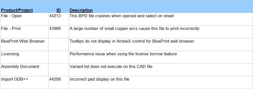
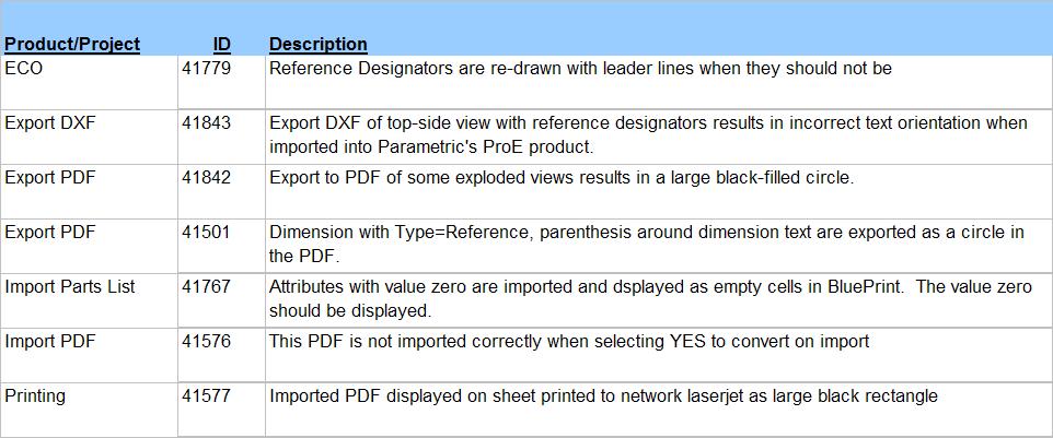
3 Parts List Import/Export Improvements. BluePrint now gives the user greater control over the Parts List data that can be imported and exported. BluePrint Imported Data is data that has been imported through a CAD Design file import or by importing Parts List information through a CSV file. BluePrint User Data is Parts List data that was created in BluePrint (typically mechanical parts). You can now: 1. Import and Export a Parts List (CSV file) with both Electrical and Mechanical parts. 2. Import and Export Imported Data only 3. Import and Export User Data only 4. Import and Export both Imported Data and User Data The new Import and Export controls are found in the Import and Export Parts List Wizards. Defect fixes for BluePrint V1.8 Build 341 Software corrections and enhancements have been made to previously existing functionality, further improving upon BluePrint s quality and reliability: Defect fixes for BluePrint V1.8 Build 339 Defect fixes for BluePrint V1.8 Build 336 DownStream Technologies, LLC, Copyright of 8


4 Defect fixes for BluePrint V1.8 Build 334 Defect fixes for BluePrint V1.8 Build 330 Defect fixes for BluePrint V1.8 Build 328 DownStream Technologies, LLC, Copyright of 8


5 Defect fixes for BluePrint V1.8 Build 326 Defect fixes for BluePrint V1.8 Build 323 Defect fixes for BluePrint V1.8 Build 321 DownStream Technologies, LLC, Copyright of 8


6 Defect fixes for BluePrint V1.8 Build 319 Defect fixes for BluePrint V1.8 Build 316 Defect fixes for BluePrint V1.8 Build 314 DownStream Technologies, LLC, Copyright of 8

7 Defect fixes for BluePrint V1.8 Build 312 DownStream Technologies, LLC, Copyright of 8

8 DownStream Technologies, LLC, Copyright of 8
Release Highlights for BluePrint-PCB Product Version 2.0.1
 Release Highlights for BluePrint-PCB Product Version 2.0.1 Introduction BluePrint Version 2.0.1 is a rolling release for BluePrint V2.0. BluePrint rolling releases are delivered as needed and allow us
Getting Started. Before You Begin, make sure you customized the following settings:
 Getting Started Getting Started Before getting into the detailed instructions for using Generative Drafting, the following tutorial aims at giving you a feel of what you can do with the product. It provides
Tiling. 1. Overlapping tiles with fixed number of tiles. Tutorial
 Tutorial Tiling Software version: Asanti 3.0 Document version: April 3, 2017 This tutorial demonstrates how to use tiling within Asanti. Download the Asanti Sample Files via the Asanti Client (Help > Asanti
Getting Started. with Easy Blue Print
 Getting Started with Easy Blue Print User Interface Overview Easy Blue Print is a simple drawing program that will allow you to create professional-looking 2D floor plan drawings. This guide covers the
Evaluation Chapter by CADArtifex
 The premium provider of learning products and solutions www.cadartifex.com EVALUATION CHAPTER 2 Drawing Sketches with SOLIDWORKS In this chapter: Invoking the Part Modeling Environment Invoking the Sketching
Quick Start for Autodesk Inventor
 Quick Start for Autodesk Inventor Autodesk Inventor Professional is a 3D mechanical design tool with powerful solid modeling capabilities and an intuitive interface. In this lesson, you use a typical workflow
SolidWorks 95 User s Guide
 SolidWorks 95 User s Guide Disclaimer: The following User Guide was extracted from SolidWorks 95 Help files and was not originally distributed in this format. All content 1995, SolidWorks Corporation Contents
Assignment 13 CAD Mechanical Part 2
 Assignment 13 CAD Mechanical Part 2 Objectives In this assignment you will learn to apply the hatch and break commands along with commands previously learned. General Instructions Hatching 1. When AutoCAD's
Lab 3 Introduction to SolidWorks I Silas Bernardoni 10/9/2008
 1 Introduction This lab is designed to provide you with basic skills when using the 3D modeling program SolidWorks. You will learn how to build parts, assemblies and drawings. You will be given a physical
Draw IT 2016 for AutoCAD
 Draw IT 2016 for AutoCAD Tutorial for System Scaffolding Version: 16.0 Copyright Computer and Design Services Ltd GLOBAL CONSTRUCTION SOFTWARE AND SERVICES Contents Introduction... 1 Getting Started...
Submittals Quick Reference Guide
 This topic provides a reference for the Project Center Submittals activity center. Purpose The Submittals activity center in Newforma Contract Management enables you to effectively log submittals and track
Sheet Metal Punch ifeatures
 Lesson 5 Sheet Metal Punch ifeatures Overview This lesson describes punch ifeatures and their use in sheet metal parts. You use punch ifeatures to simplify the creation of common and specialty cut and
Getting Started. Right click on Lateral Workplane. Left Click on New Sketch
 Getting Started 1. Open up PTC Pro/Desktop by either double clicking the icon or through the Start button and in Programs. 2. Once Pro/Desktop is open select File > New > Design 3. Close the Pallet window
Getting Started Guide
 SOLIDWORKS Getting Started Guide SOLIDWORKS Electrical FIRST Robotics Edition Alexander Ouellet 1/2/2015 Table of Contents INTRODUCTION... 1 What is SOLIDWORKS Electrical?... Error! Bookmark not defined.
Anchor Block Draft Tutorial
 Anchor Block Draft Tutorial In the following tutorial you will create a drawing of the anchor block shown. The tutorial covers such topics as creating: Orthographic views Section views Auxiliary views
GIMP WEB 2.0 ICONS. Web 2.0 Icons: Paperclip Completed Project
 GIMP WEB 2.0 ICONS WEB 2.0 ICONS: PAPERCLIP OPEN GIMP or Web 2.0 Icons: Paperclip Completed Project Step 1: To begin a new GIMP project, from the Menu Bar, select File New. At the Create a New Image dialog
Activity 1 Modeling a Plastic Part
 Activity 1 Modeling a Plastic Part In this activity, you will model a plastic part. When completed, your plastic part should look like the following two illustrations. While building this model, take time
Modeling Basic Mechanical Components #1 Tie-Wrap Clip
 Modeling Basic Mechanical Components #1 Tie-Wrap Clip This tutorial is about modeling simple and basic mechanical components with 3D Mechanical CAD programs, specifically one called Alibre Xpress, a freely
Introduction to Parametric Modeling AEROPLANE. Design & Communication Graphics 1
 AEROPLANE Design & Communication Graphics 1 Object Analysis sheet Design & Communication Graphics 2 Aeroplane Assembly The part files for this assembly are saved in the folder titled Aeroplane. Open an
House Design Tutorial
 House Design Tutorial This House Design Tutorial shows you how to get started on a design project. The tutorials that follow continue with the same plan. When you are finished, you will have created a
After completing this lesson, you will be able to:
 LEARNING OBJECTIVES After completing this lesson, you will be able to: 1. Create a Circle using 6 different methods. 2. Create a Rectangle with width, chamfers, fillets and rotation. 3. Set Grids and Increment
Radial dimension objects are available for placement in the PCB Editor only. Use one of the following methods to access a placement command:
 Radial Dimension Old Content - visit altium.com/documentation Modified by on 20-Nov-2013 Parent page: Objects A placed Radial Dimension. Summary A radial dimension is a group design object. It allows for
Solidworks tutorial. drawing. A u t h o r : M. G h a s e m i. C o n t a c t u s : i n f s o l i d w o r k s a d v i s o r.
 Solidworks tutorial drawing A u t h o r : M. G h a s e m i C o n t a c t u s : i n f o @ s o l i d w o r k s a d v i s o r. c o m The manufacturing techniques had a vast development during the past decades.
Video Tutorials Included on DVD
 Instruction Manual Video Tutorials Included on DVD With Instruction Manual, view the instructional movies providing supplementary information about cutwork creation. Please visit us at http://solutions.brother.com
Space Information User Guide
 LSE Estates Division Space Information User Guide How to access space information and floor plans on Planon For more information, contact the Estates Systems Admin team: Chris Anderson (Systems Manager),
The Toolbars submenu selects or deselects the following toolbars, below shows you how to display the Measuring Toolbar: Scale X in Y
 The Measurement Toolbars Menu The Toolbars submenu selects or deselects the following toolbars, below shows you how to display the Measuring Toolbar: As it looks on the tool bar, below Arrow End Style
Tutorial 2: Setting up the Drawing Environment
 Drawing size With AutoCAD all drawings are done to FULL SCALE. The drawing limits will depend on the size of the items being drawn. For example if our drawing is the plan of a floor 23.8m X 15m then we
House Design Tutorial
 Chapter 2: House Design Tutorial This House Design Tutorial shows you how to get started on a design project. The tutorials that follow continue with the same plan. When you are finished, you will have
How to Create Website Banners
 How to Create Website Banners In the following instructions you will be creating banners in Adobe Photoshop Elements 6.0, using different images and fonts. The instructions will consist of finding images,
MYGRAPHICSLAB: ADOBE ILLUSTRATOR CS6
 REFINE STROKES MYGRAPHICSLAB: ADOBE ILLUSTRATOR CS6 IN THIS LESSON, YOU WILL LEARN THAT: Defining the features of generated strokes is an important skill for creating illustrations Strokes can have: Different
Stratigraphy Modeling Boreholes and Cross Sections
 GMS TUTORIALS Stratigraphy Modeling Boreholes and Cross Sections The Borehole module of GMS can be used to visualize boreholes created from drilling logs. Also three-dimensional cross sections between
Welcome to Corel DESIGNER, a comprehensive vector-based package for technical graphic users and technical illustrators.
 Workspace tour Welcome to Corel DESIGNER, a comprehensive vector-based package for technical graphic users and technical illustrators. This tutorial will help you become familiar with the terminology and
Estimated Time Required to Complete: 45 minutes
 Estimated Time Required to Complete: 45 minutes This is the first in a series of incremental skill building exercises which explore sheet metal punch ifeatures. Subsequent exercises will address: placing
Creo Revolve Tutorial
 Creo Revolve Tutorial Setup 1. Open Creo Parametric Note: Refer back to the Creo Extrude Tutorial for references and screen shots of the Creo layout 2. Set Working Directory a. From the Model Tree navigate
Section 1. Introduction and Review. Objectives: Log on to the computer Launch AutoCAD Create, open, and save a drawing Review AutoCAD basics
 Section 1 Introduction and Review Objectives: Log on to the computer Launch AutoCAD Create, open, and save a drawing Review AutoCAD basics Drawing Assignments: NCAA Basketball Court Plot Style Table (Check-off)
Learning Guide. ASR Automated Systems Research Inc. # Douglas Crescent, Langley, BC. V3A 4B6. Fax:
 Learning Guide ASR Automated Systems Research Inc. #1 20461 Douglas Crescent, Langley, BC. V3A 4B6 Toll free: 1-800-818-2051 e-mail: support@asrsoft.com Fax: 604-539-1334 www.asrsoft.com Copyright 1991-2013
PosterArtist Quick Guide
 PosterArtist Quick Guide Create posters in four easy steps STEP STEP STEP STEP Use Auto Design to Create Posters Simply select a poster type and a design image to automatically create high-quality posters.
Version 9 Tutorial and User Guide
 Version 9 Tutorial and User Guide 800-989-4243 214-340-9436 support@vertigraph.com www.vertigraph.com 1 Table of Contents A. Overview... 4 B. About the SiteWorx/OS Window... 4 C. File Types Raster, Vector
MAKING THE FAN HOUSING
 Our goal is to make the following part: 39-245 RAPID PROTOTYPE DESIGN CARNEGIE MELLON UNIVERSITY SPRING 2007 MAKING THE FAN HOUSING This part is made up of two plates joined by a cylinder with holes in
Chapter 2. Drawing Sketches for Solid Models. Learning Objectives
 Chapter 2 Drawing Sketches for Solid Models Learning Objectives After completing this chapter, you will be able to: Start a new template file to draw sketches. Set up the sketching environment. Use various
Chief Architect X3 Training Series. Layers and Layer Sets
 Chief Architect X3 Training Series Layers and Layer Sets Save time while creating more detailed plans Why do you need Layers? Setting up Layer Lets Adding items to layers Layers and Layout Pages Layer
AutoCAD 2D I. Module 16. Isometric and Dimensioning. IAT Curriculum Unit PREPARED BY. January 2011
 AutoCAD 2D I Module 16 Isometric and Dimensioning PREPARED BY IAT Curriculum Unit January 2011 Institute of Applied Technology, 2011 Module 16 Auto CAD Self-paced Learning Modules AutoCAD 2D Isometric
House Design Tutorial
 House Design Tutorial This House Design Tutorial shows you how to get started on a design project. The tutorials that follow continue with the same plan. When you are finished, you will have created a
House Design Tutorial
 Chapter 2: House Design Tutorial This House Design Tutorial shows you how to get started on a design project. The tutorials that follow continue with the same plan. When you are finished, you will have
Alibre Design Exercise Manual Introduction to Sheet Metal Design
 Alibre Design Exercise Manual Introduction to Sheet Metal Design Copyrights Information in this document is subject to change without notice. The software described in this documents is furnished under
Measurement calibration in Video ToolBox Software. An example using a ruler
 Measurement calibration in Video ToolBox Software An example using a ruler Video ToolBox is capable of precise measurement using a number of different measurement tools. To use the measurement tools it
Working with Detail Components and Managing DetailsChapter1:
 Chapter 1 Working with Detail Components and Managing DetailsChapter1: In this chapter, you learn how to use a combination of sketch lines, imported CAD drawings, and predrawn 2D details to create 2D detail
5 TIPS FOR SPECIFYING PCB HOLE SIZE TOLERANCE
 One of the more forgotten topics in PCB design are the holes through which components are mounted. Specifying the tolerance of hole dimensions in PCB fabrication ensures proper fit of plated-through-hole
Alibre Design Tutorial: Loft, Extrude, & Revolve Cut Loft-Tube-1
 Alibre Design Tutorial: Loft, Extrude, & Revolve Cut Loft-Tube-1 Part Tutorial Exercise 5: Loft-Tube-1 [Complete] In this Exercise, We will set System Parameters first, then part options. Then, in sketch
12. Creating a Product Mockup in Perspective
 12. Creating a Product Mockup in Perspective Lesson overview In this lesson, you ll learn how to do the following: Understand perspective drawing. Use grid presets. Adjust the perspective grid. Draw and
Chapter 4: Displaying Waveforms
 Chapter 4: Displaying Waveforms Opening a Waveform File NetPower Waveform provides the ability to open and display a selected waveform file. Once open, all of the information that NetPower Waveform displays
USER GUIDE to COGNOS POWERPLAY
 USER GUIDE to COGNOS POWERPLAY Cognos PowerPlay lets you view and work with cube data in a Web browser. With Cognos PowerPlay you can - explore information, either one dimension at a time or using multiple
Module 1C: Adding Dovetail Seams to Curved Edges on A Flat Sheet-Metal Piece
 1 Module 1C: Adding Dovetail Seams to Curved Edges on A Flat Sheet-Metal Piece In this Module, we will explore the method of adding dovetail seams to curved edges such as the circumferential edge of a
Published on Online Documentation for Altium Products (http://www.altium.com/documentation)
") Published on Online Documentation for Altium Products (http://www.altium.com/documentation) Главная > Controlled Depth Drilling, or Back Drilling Новая эра документации Modified by Jun Chu on Apr 11, 2017
Published on Online Documentation for Altium Products (http://www.altium.com/documentation) Главная > Controlled Depth Drilling, or Back Drilling Новая эра документации Modified by Jun Chu on Apr 11, 2017
Scribble Maps Tutorial
 Scribble Maps Tutorial Go to the homepage of Scribble Maps here: h t t p : / / w w w. s c r i b b l e m a p s. c o m / Getting to know the Interface Scribble Maps is a free online mapping application with
Toothbrush Holder. A drawing of the sheet metal part will also be created.
 Prerequisite Knowledge Previous knowledge of the following commands is required to complete this lesson; Sketch (Line, Centerline, Circle, Add Relations, Smart Dimension,), Extrude Boss/Base, and Edit
7.0 - MAKING A PEN FIXTURE FOR ENGRAVING PENS
 7.0 - MAKING A PEN FIXTURE FOR ENGRAVING PENS Material required: Acrylic, 9 by 9 by ¼ Difficulty Level: Advanced Engraving wood (or painted metal) pens is a task particularly well suited for laser engraving.
Objectives Learn how to import and display shapefiles in GMS. Learn how to convert the shapefiles to GMS feature objects. Required Components
 v. 10.3 GMS 10.3 Tutorial Importing, displaying, and converting shapefiles Objectives Learn how to import and display shapefiles in GMS. Learn how to convert the shapefiles to GMS feature objects. Prerequisite
Drawing Layouts Paper space & Model Space
 Drawing Layouts Paper space & Model Space Users of Bricscad will have seen the tabs at the bottom left of the drawings area labelled: Model, Layout1, Layout2 but may not know how to use them or what they
Stratigraphy Modeling Boreholes and Cross. Become familiar with boreholes and borehole cross sections in GMS
 v. 10.3 GMS 10.3 Tutorial Stratigraphy Modeling Boreholes and Cross Sections Become familiar with boreholes and borehole cross sections in GMS Objectives Learn how to import borehole data, construct a
Objectives Learn how to import and display shapefiles with and without ArcObjects. Learn how to convert the shapefiles to GMS feature objects.
 v. 10.1 GMS 10.1 Tutorial Importing, displaying, and converting shapefiles Objectives Learn how to import and display shapefiles with and without ArcObjects. Learn how to convert the shapefiles to GMS
Tutorial 1 getting started with the CNCSimulator Pro
 CNCSimulator Blog Tutorial 1 getting started with the CNCSimulator Pro Made for Version 1.0.6.5 or later. The purpose of this tutorial is to learn the basic concepts of how to use the CNCSimulator Pro
FlashChart. Symbols and Chart Settings. Main menu navigation. Data compression and time period of the chart. Chart types.
 FlashChart Symbols and Chart Settings With FlashChart you can display several symbols (for example indices, securities or currency pairs) in an interactive chart. You can also add indicators and draw on
Architecture 2012 Fundamentals
 Autodesk Revit Architecture 2012 Fundamentals Supplemental Files SDC PUBLICATIONS Schroff Development Corporation Better Textbooks. Lower Prices. www.sdcpublications.com Tutorial files on enclosed CD Visit
Rhinoceros modeling tools for designers. Using Layouts in Rhino 5
 Rhinoceros modeling tools for designers Using Layouts in Rhino 5 RH50-TM-LAY-Apr-2014 Rhinoceros v5.0, Layouts, Training Manual Revised April 8, 2014, Mary Fugier mary@mcneel.com Q&A April 8, 2014, Lambertus
Advance Dimensioning and Base Feature Options
 Chapter 4 Advance Dimensioning and Base Feature Options Learning Objectives After completing this chapter you will be able to: Dimension the sketch using the autodimension sketch tool. Dimension the sketch
Chapter 9 Organization Charts, Flow Diagrams, and More
 Draw Guide Chapter 9 Organization Charts, Flow Diagrams, and More This PDF is designed to be read onscreen, two pages at a time. If you want to print a copy, your PDF viewer should have an option for printing
PCB Draftsman. Key features. Modified by on 29-Nov-2016
 PCB Draftsman Old Content - visit altium.com/documentation Modified by on 29-Nov-2016 To provide further content flexibility and detail in the output files published for PCB manufacture, Altium Designer 16.1offers
Creating a Frame by Frame Animation for PhotoStory
 Creating a Frame by Frame Animation for PhotoStory There are an unlimited number of animation styles that you can create using the PhotoShop Elements software. Depending on the type of animation you want,
SolidWorks Tutorial 1. Axis
 SolidWorks Tutorial 1 Axis Axis This first exercise provides an introduction to SolidWorks software. First, we will design and draw a simple part: an axis with different diameters. You will learn how to
ARCHICAD Introduction Tutorial
 Starting a New Project ARCHICAD Introduction Tutorial 1. Double-click the Archicad Icon from the desktop 2. Click on the Grey Warning/Information box when it appears on the screen. 3. Click on the Create
Assignment 12 CAD Mechanical Part 2
 Assignment 12 CAD Mechanical Part 2 Objectives In this assignment you will learn to apply the hidden lines, isometric snap, and ellipses commands along with commands previously learned.. General Hidden
TABLE OF CONTENTS. INTRODUCTION...5 Advance Steel...5 Where to find information?...6 Contacting technical support...6
 TABLE OF CONTENTS INTRODUCTION...5 Advance Steel...5 Where to find information?...6 Contacting technical support...6 INSTALLATION...7 System requirements...7 Starting the installation...7 STARTING ADVANCE
Appendix R5 6. Engineering Drafting. Broken View
 Updating Using Autodesk Inventor to Release 5 Appendix R5 6 Engineering Drafting Chapter 6 delineates the concepts of engineering drafting. You output orthographic views from solid parts and orthographic
TABLE OF CONTENTS INTRODUCTION...4
 Starting Guide TABLE OF CONTENTS INTRODUCTION...4 Advance Steel... 4 Where to find information?... 5 INSTALLATION... 5 System requirements... 5 Starting the installation... 5 STARTING ADVANCE STEEL...
Principles and Practice
 Principles and Practice An Integrated Approach to Engineering Graphics and AutoCAD 2011 Randy H. Shih Oregon Institute of Technology SDC PUBLICATIONS www.sdcpublications.com Schroff Development Corporation
Solid Part Four A Bracket Made by Mirroring
 C h a p t e r 5 Solid Part Four A Bracket Made by Mirroring This chapter will cover the following to World Class standards: Sketch of a Solid Problem Draw a Series of Lines Finish the 2D Sketch Extrude
High Speed Motion Trail Effect With Photoshop
 High Speed Motion Trail Effect With Photoshop Written by Steve Patterson. In this Photo Effects tutorial, we'll learn how to add a sense of speed to an object using an easy to create motion blur effect!
Imaging Features Available in HTML5. it just makes sense
 Imaging Features Available in HTML5 it just makes sense August, 2018 Imaging Features Available in HTML5 As part of the 5.2 SP1 release, the Images functionality is now available in HTML5 and provides
House Design Tutorial
 Chapter 2: House Design Tutorial This House Design Tutorial shows you how to get started on a design project. The tutorials that follow continue with the same plan. When we are finished, we will have created
Release Notes - Fixes in Tekla Structures 2016i PR1
 Release Notes - Fixes in Tekla Structures 2016i PR1, you can now set the to either or. is modified., the ID of the connection plate is not changed anymore when the connection now uses normal rebar groups
SCHEDULE USER GUIDE. Version Noventri Suite Schedule User Guide SF100E REV 08
 SCHEDULE USER GUIDE Version 2.0 1 Noventri Suite Schedule User Guide SF100E-0162-02 REV 08 Table of Contents 1. SCHEDULE... 3 1.1 Overview... 3 1.2 Start SCHEDULE... 3 1.3 Select Project... 4 1.4 Select
Revit Structure 2012 Basics:
 SUPPLEMENTAL FILES ON CD Revit Structure 2012 Basics: Framing and Documentation Elise Moss autodesk authorized publisher SDC PUBLICATIONS www.sdcpublications.com Schroff Development Corporation Structural
Editing and Digitizing in EDS III
 Editing and Digitizing in EDS III Design Editing Tablet and On-Screen Digitizing Embroidery and Chenille Stitching Scanning Compatibilities Part Number 110221-01, Revision A A Saurer Group Company 1575
USING LAYERS. Chapter 18 - Layers 117
 USING LAYERS KNOWLEDGE AND UNDERSTANDING After completing this module, you will know and understand the theory regarding: layers different layer settings the use of layers in templates APPLICATION OF KNOWLEDGE
User Guide. Version 1.2. Copyright Favor Software. Revised:
 User Guide Version 1.2 Copyright 2009-2010 Favor Software Revised: 2010.05.18 Table of Contents Introduction...4 Installation on Windows...5 Installation on Macintosh...6 Registering Intwined Pattern Studio...7
Release Notes - Fixes in Tekla Structures 2016i SP1
 Release Notes - Fixes in Tekla Structures 2016i SP1 is modified., the ID of the connection plate is not changed anymore when the connection now uses normal rebar groups instead of tapered groups., the
User Guide. Version 1.4. Copyright Favor Software. Revised:
 User Guide Version 1.4 Copyright 2009-2012 Favor Software Revised: 2012.02.06 Table of Contents Introduction... 4 Installation on Windows... 5 Installation on Macintosh... 6 Registering Intwined Pattern
TeleTrader FlashChart
 TeleTrader FlashChart Symbols and Chart Settings With TeleTrader FlashChart you can display several symbols (for example indices, securities or currency pairs) in an interactive chart. You can also add
Making Standard Note Blocks and Placing the Bracket in a Drawing Border
 C h a p t e r 12 Making Standard Note Blocks and Placing the Bracket in a Drawing Border In this chapter, you will learn the following to World Class standards: Making standard mechanical notes Using the
AEROPLANE. Create a New Folder in your chosen location called Aeroplane. The four parts that make up the project will be saved here.
 AEROPLANE Prerequisite Knowledge Previous knowledge of the following commands is required to complete this lesson. Sketching (Line, Rectangle, Arc, Add Relations, Dimensioning), Extrude, Assemblies and
J. La Favre Fusion 360 Lesson 2 April 19, 2017
 In this lesson, you will create a round plate with 12 counter-bored holes to fit 6-32 socket head screws. A counter-bored hole has two diameters, one to fit the threaded part of the screw and the other
User Guide V10 SP1 Addendum
 Alibre Design User Guide V10 SP1 Addendum Copyrights Information in this document is subject to change without notice. The software described in this document is furnished under a license agreement or
When you complete this assignment you will:
 Objjectiives When you complete this assignment you will: 1. create an engineering drawing file using the management file menu. 2. dimension the engineering file using the drawing annotation menu. 3. produce
Levels. Chapter Nine PLAY VIDEO INTRODUCTION LEVEL MANAGER AND LEVEL DISPLAY DIALOGS LEVEL MANAGER DIALOG
 Chapter Nine Levels PLAY VIDEO INTRODUCTION A design file consists of any number of levels. A level is a way of separating CAD data much the same way as a clear sheet of acetate is used by an architect
Bottom Rail. Chapter 2. Chair. A. Weldments Toolbar. Step 1. Click File Menu > New, click Part and OK. B. 3D Sketch.
 Chapter 2 Chair Bottom Rail A. Weldments Toolbar. Step 1. Click File Menu > New, click Part and OK. Step 2. Right click Sketch on the Command Manager toolbar and select Weldments, Fig. 1. Step 3. Click
2. Creating and using tiles in Cyberboard
 2. Creating and using tiles in Cyberboard I decided to add some more detail to the first hexed grip map that I produced (Demo1) using the Cyberboard Design program. To do this I opened program by clicking
g. Click once on the left vertical line of the rectangle.
 This drawing will require you to a model of a truck as a Solidworks Part. Please be sure to read the directions carefully before constructing the truck in Solidworks. Before submitting you will be required
Working With Drawing Views-I
 Chapter 12 Working With Drawing Views-I Learning Objectives After completing this chapter you will be able to: Generate standard three views. Generate Named Views. Generate Relative Views. Generate Predefined
Open Adobe Photoshop CS3 or CS4. Then open the JPG created from the SketchUp model from within Photoshop. File menu > Open
 Open Adobe Photoshop CS3 or CS4. Then open the JPG created from the SketchUp model from within Photoshop. File menu > Open Go to View>Rulers to turn them on they should appear on the sides of each open