Technical Drawing Paper II(A) Higher Level (Engineering Applications)
|
|
|
- Thomasine Ferguson
- 5 years ago
- Views:
Transcription
1 Coimisiún na Scrúduithe Stáit State Examinations Commission M84 Leaving Certificate Examination 2007 Technical Drawing Paper II(A) Higher Level (Engineering Applications) (200 Marks) Friday 15 June Afternoon, Instructions (a) Ensure that you have received examination paper M84(L) which accompanies this paper. Answer any four questions. All questions carry equal marks. (c) Drawings and sketches should be in pencil unless otherwise stated. (d) Where dimensions are omitted they may be estimated. (e) Credit will be given for neat orderly presentation of work. (f) Work on one side of the paper only. (g) The Examination Number should be written on each drawing sheet used. (h) First or third angle projection may be used. NOTE: All drawings are shown on examination paper M84(L) which accompanies this paper. Page 1 of 5
2 1. Details of a Belt Tensioning Unit are given in Fig. 1 with the parts list tabulated below. (a) (c) Draw a full size sectional elevation A-A showing the parts fully assembled. Insert item reference numbers to identify the parts and add the title: BELT TENSIONING UNIT. Using a neat freehand sketch suggest a basic design modification that will allow lubricant to be applied between part 4 and part 7. PART NAME REQUIRED 1 BODY 1 2 PULLEY 1 3 M10 SCREW 1 4 BUSH 2 5 M24 NUT 1 6 M24 WASHER 1 7 ECCENTRIC SHAFT 1 2. (a) Draw the profile and displacement diagram for a plate cam rotating at one revolution per second, in an anti-clockwise direction, and imparting the following motion to an in-line roller follower of 20mm diameter: second second second second rise 40mm with simple harmonic motion; dwell; fall 40mm with uniform acceleration and retardation; dwell. The nearest approach of the roller centre to the camshaft centre is 45mm. The camshaft diameter is 25mm. In the mechanism shown in Fig. 2, the crank OA rotates clockwise about the fixed point O at a constant speed. The rod AB connects to the link CE by a pin joint at B. During one revolution of OA the end C of the link CE slides from C to D and back to C again. Draw, full size, the mechanism in its given starting position, and plot the locus of point E during one complete revolution of crank OA. Page 2 of 5
3 3. The elevation and plan of a sheet metal transition piece, which is connected to a circular duct, are shown in Fig. 3. (a) (c) Draw, to a scale of 1:10, the given views and produce a one-piece surface development of the transition piece with the seam at S-S. State the minimum size of rectangular sheet that will contain the development. Make neat freehand sketches of: (i) (ii) (iii) A sheet metal joint which would be suitable for the seam S-S; A safe edge suitable for the open bottom of the transition piece; A sheet metal joint which would be suitable for connecting the transition piece to the circular duct. Include the title of the sheet metal joint/edge below each sketch. 4. (a) The projections of a v-block clamp are shown in Fig. 4. Make an exploded isometric drawing of the v-block. The drawing should show clearly how the parts labelled 1, 2 and 3 are assembled. Make corner X the lowest point on your drawing. Hidden detail is not required. Make a neat freehand sketch of a typical universal joint. 5. The elevation and plan of a pump housing are given in Fig. 5. A pictorial sketch of the housing is also shown. (a) Draw the following views (Hidden detail is not required): (i) A sectional elevation on A-A; (ii) A sectional plan on B-B; (iii) An end elevation viewed in the direction of arrow C. Insert the following on the drawing: (i) (ii) (iii) Four leading dimensions; The appropriate ISO projection symbol; Title: PUMP HOUSING. Page 3 of 5
4 6. Answer SECTION A or SECTION B but not both. SECTION A (a) Draw, full size, two involute teeth of a gear wheel with 24 teeth, module 10 and a pressure angle of Tabulate on the sheet the following values for the gear wheel: Addendum Pitch Circle Diameter Tooth Thickness Dedendum Circular Pitch Base Circle Diameter A sectional elevation of a universal cylinder, with the piston rod in the fully retracted position, is shown in Fig. 6(a). (i) (ii) Make a large neat freehand sectional sketch of the assembly showing the piston rod in the fully extended position. Identify and neatly label on the sketch the following five parts: Piston, Cylinder, Rod seal, Piston seal, and Cylinder seal. Page 4 of 5
5 (a) (c) (d) OR SECTION B Briefly answer any six of the following questions. (Sketches should be used where appropriate) (i) State four advantages that CAD offers over traditional drawing methods; (ii) Identify two specific input devices and two specific output devices in a CAD system; (iii) State two potential problems which should be considered when downloading CAD files from the Internet; (iv) Name two settings that would typically be included in a template drawing; (v) Using a sketch, show how layers may be used in a CAD drawing; (vi) Sketch an example of Baseline dimensioning; (vii) Explain the term Aliasing on a CAD display; (viii) Explain what is meant by the term Parametric CAD System. Name a CAD package that could be used to produce the 3D solid model of the component shown in Fig. 6. Using sketches, where appropriate, briefly outline the various steps involved and the commands used in generating the CAD model. With reference to CAD, and using freehand sketches where appropriate, explain the difference between the following pairs of terms: (i) (ii) (iii) (iv) (v) Extend and Lengthen; Lineweight and Linetype; Pan and Zoom; Wireframe model and Surface model; Viewpoint and Viewport. Draw, full size, the object that would be displayed on a CAD system when the following commands are executed. The origin (0,0) is located at the lower left corner of the display. Sheet size is set. Lower left corner (0,0) and upper right corner (297,210). A semi ellipse is drawn with a major axis start point of (40,90) and a major axis end point of (260,90). The minor axis is 140mm long and the semi ellipse passes through the point (150,160) on the minor axis. Two circles are drawn as follows: Circle 1: centre (220,90), radius 15 Circle 2: centre (250,90), radius 5 Circle 2 is selected and subjected to a polar (circular) array. The centre point of the array is (220,90) and the fill angle is 270 0, measured in an anticlockwise direction. The total number of items in the array is 3. Two lines AB and BC are drawn using the following absolute coordinates: A (40,90) B (50,80) C (60,90) The lines AB and BC are subject to a rectangular array with one row, five columns and with a distance of 20 between the columns. A 3-point arc is drawn. Start point (180,90), second point (220,50) and end point (260,90). A line is drawn, starting at the point (140,90) and ending at the point defined by the relative polar coordinates (@40<0). The intersection between the line and the arc is filleted using a radius of 10. The text LOCKING PLATE is inserted. The text is centre justified, with a centre point of text (150,20), a text height of 5mm and a text rotation angle of 0 0. Page 5 of 5
6 Coimisiún na Scrúduithe Stáit State Examinations Commission M84(L) Scrúdú Ardteistiméireachta 2007 Leaving Certificate Examination 2007 Líníocht Theicniúil Technical Drawing Páipéar II(A) Ardleibhéal Paper II(A) Higher Level (Feidhmiúcháin Innealtóireachta) (Engineering Applications) Dé haoine 15 Meitheamh, Tráthnóna, Friday 15 June, Afternoon, NÓTA: Deimhnigh go bhfuair tú scrúdpháipéar M84, a ghabhann leis an bpáipéar seo. NOTE: Ensure that you have received examination paper M84 which accompanies this paper. Page 1 of 6 / Lch. 1 de 6
7 Page 2 of 6 / Lch. 2 de 6 Fillets / Filléid R3 Fig. 1 / Fíor 1
8 Page 3 of 6 / Lch. 3 de 6 OA = 40 AB = 120 CB = 120 CE = 150 Fig. 2 / Fíor 2 Fig. 3 / Fíor 3
9 Page 4 of 6 / Lch. 4 de 6 Fig. 4 / Fíor 4


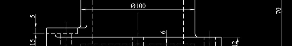
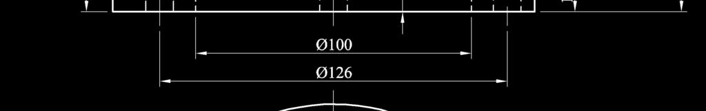
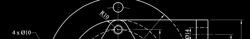
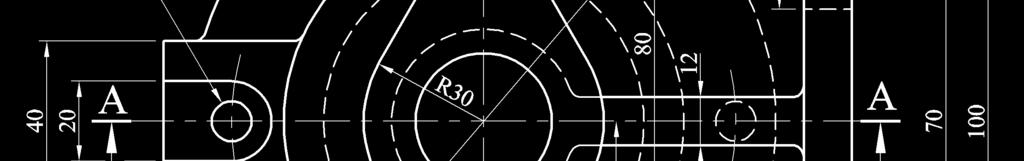
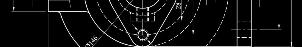

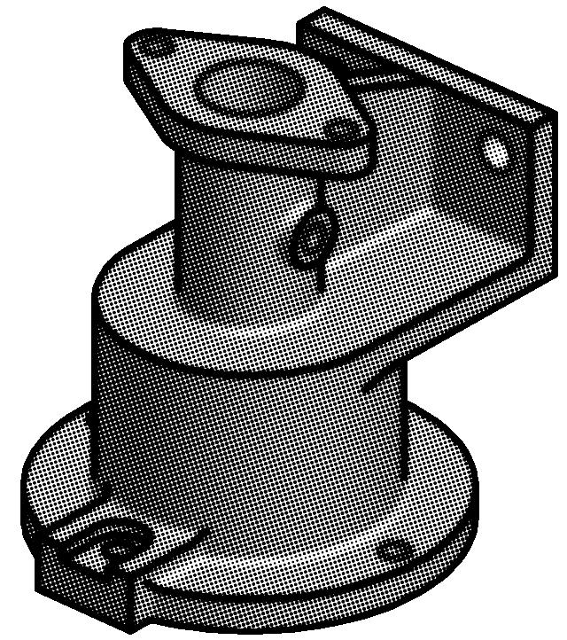
10 Fig. 5 / Fíor 5 Page 5 of 6 / Lch. 5 de 6
11 Fig. 6(a) / Fíor 6(a) Page 6 of 6 / Lch. 6 de 6 Fig. 6 / Fíor 6
TECHNICAL DRAWING - ORDINARY LEVEL PAPER II (A) ENGINEERING APPLICATIONS
 ENGINEERING APPLICATIONS") M.82 AN ROINN OIDEACHAIS AGUS EOLAÍOCHTA LEAVING CERTIFICATE EXAMINATION 2002 TECHNICAL DRAWING - ORDINARY LEVEL PAPER II (A) ENGINEERING APPLICATIONS 200 marks FRIDAY, 14 JUNE - AFTERNOON 2.00 p.m. 5.00
M.82 AN ROINN OIDEACHAIS AGUS EOLAÍOCHTA LEAVING CERTIFICATE EXAMINATION 2002 TECHNICAL DRAWING - ORDINARY LEVEL PAPER II (A) ENGINEERING APPLICATIONS 200 marks FRIDAY, 14 JUNE - AFTERNOON 2.00 p.m. 5.00
TECHNICAL DRAWING HIGHER LEVEL PAPER II(A) ENGINEERING APPLICATIONS
 ENGINEERING APPLICATIONS") M. 84 AN ROINN OIDEACHAIS AGUS EOLAÍOCHTA LEAVING CERTIFICATE EXAMINATION, 2001 TECHNICAL DRAWING HIGHER LEVEL PAPER II(A) ENGINEERING APPLICATIONS Friday, 15 June, Afternoon 2.00 5.00 p.m. 200 Marks INSTRUCTIONS
M. 84 AN ROINN OIDEACHAIS AGUS EOLAÍOCHTA LEAVING CERTIFICATE EXAMINATION, 2001 TECHNICAL DRAWING HIGHER LEVEL PAPER II(A) ENGINEERING APPLICATIONS Friday, 15 June, Afternoon 2.00 5.00 p.m. 200 Marks INSTRUCTIONS
Design & Communication Graphics Ordinary Level Sections B and C (180 marks)
") Coimisiún na Scrúduithe Stáit State Examinations Commission 2010. M80BC Leaving Certificate Examination, 2010 Design & Communication Graphics Ordinary Level Sections B and C (180 marks) Friday, 18 June
Coimisiún na Scrúduithe Stáit State Examinations Commission 2010. M80BC Leaving Certificate Examination, 2010 Design & Communication Graphics Ordinary Level Sections B and C (180 marks) Friday, 18 June
Design & Communication Graphics Ordinary Level Sections B and C (180 marks)
") Coimisiún na Scrúduithe Stáit State Examinations Commission 2013. M80BC Leaving Certificate Examination, 2013 Design & Communication Graphics Ordinary Level Sections B and C (180 marks) Wednesday, 19 June
Coimisiún na Scrúduithe Stáit State Examinations Commission 2013. M80BC Leaving Certificate Examination, 2013 Design & Communication Graphics Ordinary Level Sections B and C (180 marks) Wednesday, 19 June
Design & Communication Graphics Higher Level Section A (60 marks)
") Coimisiún na Scrúduithe Stáit State Examinations Commission 2011. M81A Leaving Certificate Examination, 2011 Design & Communication Graphics Higher Level Section A (60 marks) Friday, 17 June Afternoon,
Coimisiún na Scrúduithe Stáit State Examinations Commission 2011. M81A Leaving Certificate Examination, 2011 Design & Communication Graphics Higher Level Section A (60 marks) Friday, 17 June Afternoon,
Technical Graphics Higher Level
 Coimisiún na Scrúduithe Stáit State Examinations Commission Junior Certificate Examination 2005 Technical Graphics Higher Level Marking Scheme Sections A and B Section A Q1. 12 Four diagrams, 3 marks for
David Anderson. Gill & Macmillan
 One Volume Edition David nderson 3 and 4 Online Worksheets Ideal as homework exercises Will save students time as the problems are already set up on the page Worksheets are referenced in the text The material
Design & Communication Graphics Higher Level Sections B and C (180 marks)
") Coimisiún na Scrúduithe Stáit State Examinations Commission 2016. M81BC Leaving Certificate Examination, 2016 Design & Communication Graphics Higher Level Sections B and C (180 marks) Wednesday, 22 June
Coimisiún na Scrúduithe Stáit State Examinations Commission 2016. M81BC Leaving Certificate Examination, 2016 Design & Communication Graphics Higher Level Sections B and C (180 marks) Wednesday, 22 June
Design & Communication Graphics Higher Level Section A (60 Marks)
") M.85A ªM.858 Leaving Certificate Examination, 2009 Design & Communication Graphics Higher Level Section A (60 Marks) Time: 3 Hours This examination is divided into three sections: SECTION A SECTION B SECTION
M.85A ªM.858 Leaving Certificate Examination, 2009 Design & Communication Graphics Higher Level Section A (60 Marks) Time: 3 Hours This examination is divided into three sections: SECTION A SECTION B SECTION
Technical Drawing Paper 1 - Higher Level (Plane and Solid Geometry)
") Coimisiún na Scrúduithe Stáit State Examinations Commission 2008. M81 Leaving Certificate Examination 2008 Technical Drawing Paper 1 - Higher Level (Plane and Solid Geometry) (200 Marks) Friday 13 June
Coimisiún na Scrúduithe Stáit State Examinations Commission 2008. M81 Leaving Certificate Examination 2008 Technical Drawing Paper 1 - Higher Level (Plane and Solid Geometry) (200 Marks) Friday 13 June
Coimisiún na Scrúduithe Stáit State Examinations Commission. Leaving Certificate Marking Scheme. Design and Communication Graphics
 Coimisiún na Scrúduithe Stáit State Examinations Commission Leaving Certificate 2016 Marking Scheme Design and Communication Graphics Ordinary Level Note to teachers and students on the use of published
ENGINEERING DRAWING IM 09 AND GRAPHICAL COMMUNICATION
 IM SYLLABUS (2014) ENGINEERING DRAWING IM 09 AND GRAPHICAL COMMUNICATION SYLLABUS Engineering Drawing and Graphical Communication IM 09 (Available in September) Syllabus 1 Paper (3 hours) Aims The aims
C A R I B B E A N E X A M I N A T I O N S C O U N C I L REPORT ON CANDIDATES WORK IN THE SECONDARY EDUCATION CERTIFICATE EXAMINATION MAY/JUNE 2010
 C A R I B B E A N E X A M I N A T I O N S C O U N C I L REPORT ON CANDIDATES WORK IN THE SECONDARY EDUCATION CERTIFICATE EXAMINATION MAY/JUNE 2010 TECHNICAL DRAWING GENERAL PROFICIENCY Copyright 2010 Caribbean
Coimisiún na Scrúduithe Stáit State Examinations Commission. Leaving Certificate Marking Scheme. Design and Communication Graphics.
 Coimisiún na Scrúduithe Stáit State Examinations Commission Leaving Certificate 2016 Marking Scheme Design and Communication Graphics Higher Level Note to teachers and students on the use of published
ENGINEERING GRAPHICS
 ENGINEERING GRAPHICS Time allowed : 3 hours Maximum Marks : 70 Note : (ii) Attempt all the questions. Use both sides of the drawing sheet, if necessary. (iii) All dimensions are in millimetres. (iv) Missing
COURSE: INTRODUCTION TO CAD GRADES: UNIT: Measurement
 UNIT: Measurement - Students will demonstrate correctness in measuring using various scales and instruments. Demonstrate the various marks that make up a ruler including 1/16, 1/8, ¼ and ½. Assessment
UNIT I PLANE CURVES AND FREE HAND SKETCHING CONIC SECTIONS
 UNIT I PLANE CURVES AND FREE HAND SKETCHING CONIC SECTIONS Definition: The sections obtained by the intersection of a right circular cone by a cutting plane in different positions are called conic sections
Design & Communication Graphics Higher Level Section A (60 Marks)
") 1 L.85A Pre-Leaving Certificate Examination, 2011 Design & Communication Graphics Higher Level Section A (60 Marks) Time: 3 Hours This examination is divided into three sections: SECTION A SECTION B SECTION
1 L.85A Pre-Leaving Certificate Examination, 2011 Design & Communication Graphics Higher Level Section A (60 Marks) Time: 3 Hours This examination is divided into three sections: SECTION A SECTION B SECTION
ORDINARY LEVEL PAST PAPERS
 ORDINARY LEVEL PAST PAPERS UNEB S4 1982 SECTION I PLANE GEOMETRY 1. (a) Construct a diagonal scale of 40mm to 10mm to read up to 20mm by 0.02mm. (b) Indicate on your scale the following readings. (i) 14.8mm.
Tutorial Guide to AutoCAD 2015
 Tutorial Guide to AutoCAD 2015 2D Drawing, 3D Modeling Shawna Lockhart SDC P U B L I C AT I O N S For Microsoft Windows Better Textbooks. Lower Prices. www.sdcpublications.com Powered by TCPDF (www.tcpdf.org)
Leaving Certificate 201
 Coimisiún na Scrúduithe Stáit State Examinations Commission Leaving Certificate 201 Marking Scheme Design and Communication Graphics Ordinary Level Note to teachers and students on the use of published
Coimisiún na Scrúduithe Stáit State Examinations Commission. Junior Certificate Marking Scheme. Technical Graphics.
 Coimisiún na Scrúduithe Stáit State Examinations Commission Junior Certificate 2013 Marking Scheme Technical Graphics Higher Level Note to teachers and students on the use of published marking schemes
Tutorial Guide to AutoCAD 2014
 Tutorial Guide to AutoCAD 2014 2D Drawing, 3D Modeling Shawna Lockhart SDC P U B L I C AT I O N S For Microsoft Windows Better Textbooks. Lower Prices. www.sdcpublications.com Visit the following websites
Tutorial Guide to AutoCAD 2013
 Tutorial Guide to AutoCAD 2013 2D Drawing, 3D Modeling Shawna Lockhart SDC P U B L I C AT I O N S Schroff Development Corporation For Microsoft Windows Better Textbooks. Lower Prices. www.sdcpublications.com
Hours / 100 Marks Seat No.
 17610 15116 4 Hours / 100 Seat No. Instructions (1) All Questions are Compulsory. (2) Answer each next main Question on a new page. (3) Illustrate your answers with neat sketches wherever necessary. (4)
Technical Graphics Ordinary Level Section A (120 marks)
") Coimisiún na Scrúduithe Stáit State Examinations Commission 2012. S60A Junior Certificate Examination, 2012 Technical Graphics Ordinary Level Section A (120 marks) Monday, 18 June Morning 9:30-12:00 Centre
Coimisiún na Scrúduithe Stáit State Examinations Commission 2012. S60A Junior Certificate Examination, 2012 Technical Graphics Ordinary Level Section A (120 marks) Monday, 18 June Morning 9:30-12:00 Centre
Leaving Certificate 2014
 Coimisiún na Scrúduithe Stáit State Examinations Commission Leaving Certificate 2014 Marking Scheme Design and Communication Graphics Higher Level Note to teachers and students on the use of published
ARC By default AutoCAD will draw an ARC through three selected points. Options can be set at the start and within the command.
 DFTG 1309 Final Review Notes I. Draw commands: LINE (draws a series of lines) Valid input: Pick button Cartesian coordinates Absolute (2,3) Relative rectangular (@2,3) Relative polar (@ 2
Technical Drawing 101 with AutoCAD 2018
 Technical Drawing 101 with AutoCAD 2018 A Multidisciplinary Guide to Drafting Theory and Practice with Video Instruction Douglas Smith Antonio Ramirez Ashleigh Fuller SDC PUBLICATIONS Better Textbooks.
Copyrighted Material. Copyrighted Material. Copyrighted. Copyrighted. Material
 Engineering Graphics ORTHOGRAPHIC PROJECTION People who work with drawings develop the ability to look at lines on paper or on a computer screen and "see" the shapes of the objects the lines represent.
ISOMETRIC PROJECTION. Contents. Isometric Scale. Construction of Isometric Scale. Methods to draw isometric projections/isometric views
 ISOMETRIC PROJECTION Contents Introduction Principle of Isometric Projection Isometric Scale Construction of Isometric Scale Isometric View (Isometric Drawings) Methods to draw isometric projections/isometric
ENGINEERING AND DESIGN
 ENGINEERING AND DESIGN EXAMINATION GUIDELINES GRADE 12 2017 These guidelines consist of 10 pages. Engineering Graphics and Design 2 DBE/2017 TABLE OF CONTENTS Page 1. INTRODUCTION 3 2. ASSESSMENT IN GRADE
Downloaded from ENGINEERING DRAWING. Time allowed : 3 hours Maximum Marks : 70
 ENGINEERING DRAWING Time allowed : 3 hours Maximum Marks : 70 Note : (i) (ii) Attempt all the questions. Use both sides of the drawing sheet, if necessary. (iii) All dimensions are in millimeters. (iv)
LABORATORY MANUAL COMPUTER AIDED DESIGN LAB
 LABORATORY MANUAL COMPUTER AIDED DESIGN LAB Sr. No 1 2 3 Experiment Title Setting up of drawing environment by setting drawing limits, drawing units, naming the drawing, naming layers, setting line types
AutoCAD LT 2010 Tutorial
 AutoCAD LT 2010 Tutorial Randy H. Shih Oregon Institute of Technology SDC PUBLICATIONS Schroff Development Corporation www.schroff.com Better Textbooks. Lower Prices. AutoCAD LT 2010 Tutorial iii Table
Machines. 6/16 Kenworth Place, BRENDALE Ph Fx RT-060S. Horizontal / Vertical Rotary Table INSTRUCTION MANUAL
 RT-060S Horizontal / Vertical Rotary Table INSTRUCTION MANUAL Horizontal / Vertical Rotary Table - Instructions There are three methods of setting positions using a rotary table. 1. Use the degree scale
Principles and Practice
 Principles and Practice An Integrated Approach to Engineering Graphics and AutoCAD 2016 Randy H. Shih SDC PUBLICATIONS Better Textbooks. Lower Prices. www.sdcpublications.com Powered by TCPDF (www.tcpdf.org)
Exploded View Saw Base - Model 7060 Semi-Automatic Cut-Off Band Saw
 Exploded View Saw Base - Model 7060 Semi-Automatic Cut-Off Band Saw 136 137 135 134 132 131 133 113 114 115 117 116 118 119 120 121 79 78 77 107 108 65 76 110 109 66 10 9 6 11 5 4 8 7 75 74 73 72 111 112
Design & Communication Graphics Higher Level Sections B and C (180 marks)
") Coimisiún na Scrúduithe Stáit State Examinations Commission 202. M8BC Leaving Certificate Examination, 202 Design & Communication Graphics Higher Level Sections B and C (80 marks) Wednesday, 20 June Afternoon,
Coimisiún na Scrúduithe Stáit State Examinations Commission 202. M8BC Leaving Certificate Examination, 202 Design & Communication Graphics Higher Level Sections B and C (80 marks) Wednesday, 20 June Afternoon,
Dean Muccio AutoCAD Interior Designer. for the. AutoCAD for Mac and PC SDC. Better Textbooks. Lower Prices.
 Dean Muccio AutoCAD 2020 for the Interior Designer AutoCAD for Mac and PC SDC P U B L I C AT I O N S Better Textbooks. Lower Prices. www.sdcpublications.com Powered by TCPDF (www.tcpdf.org) Visit the following
Dharmapuri LAB MANUAL. : B.E. - Civil Engineering Year & Semester : I Year / II Semester
 Dharmapuri 636 703 LAB MANUAL Regulation : 2013 Branch : B.E. - Civil Engineering Year & Semester : I Year / II Semester CE6261-COMPUTER AIDED DRAFTING AND MODELLING LABORATORY ICAL ENG VVIT DEPARTMENT
Dean Muccio. AutoCAD 2018 for the. Interior Designer. AutoCAD for Mac and PC SDC. Better Textbooks. Lower Prices.
 Dean Muccio AutoCAD 2018 for the Interior Designer AutoCAD for Mac and PC SDC P U B L I C AT I O N S Better Textbooks. Lower Prices. www.sdcpublications.com Powered by TCPDF (www.tcpdf.org) Visit the following
Teach Yourself UG NX Step-by-Step
 Teach Yourself UG NX Step-by-Step By Hui Zhang Ph.D., P.Eng. www.geocities.com/zhanghui1998 Table of Contents Chapter 1 Introduction... 1 1.1 UG NX User Interface... 1 1.2 Solid Modeling Fundamentals...
ENGINEERING DRAWING AM 09
 AM SYLLABUS (2014) ENGINEERING DRAWING AM 09 SYLLABUS 1 Engineering Drawing AM09 (Available in September) Syllabus Paper I (3 hrs) + Paper II (3 hrs) + coursework Aims The aims of the syllabus are to further
Mechanical Engineering Design Portfolio. Syed Ibrahim Dilawer (B.Eng Mechanical, MSc Manufacturing Management)
") Mechanical Engineering Design Portfolio Syed Ibrahim Dilawer (B.Eng Mechanical, MSc Manufacturing Management) INDEX Mechanical Projects:- Analysis and design of Epicyclic Gear Trains Designing SAE BAJA
Mechanical Engineering Design Portfolio Syed Ibrahim Dilawer (B.Eng Mechanical, MSc Manufacturing Management) INDEX Mechanical Projects:- Analysis and design of Epicyclic Gear Trains Designing SAE BAJA
Parametric Modeling with Creo Parametric 2.0
 Parametric Modeling with Creo Parametric 2.0 An Introduction to Creo Parametric 2.0 Randy H. Shih SDC PUBLICATIONS Schroff Development Corporation Better Textbooks. Lower Prices. www.sdcpublications.com
ENGINEERING GRAPHICS AND DESIGN EXAMINATION GUIDELINES GRADE 12
 ENGINEERING GRAPHICS AND DESIGN EXAMINATION GUIDELINES GRADE 12 2014 These guidelines consist of 10 pages. Engineering Graphics and Design 2 DBE/2014 TABLE OF CONTENTS Page 1. Introduction 3 2. Assessment
CDT: DESIGN AND COMMUNICATION
 CDT: DESIGN AND COMMUNICATION Paper 7048/01 Structured Key message Whilst many excellent answers were seen, the following were considered to be areas where improvement could be made: the correct positioning
Principles and Practice:
 Principles and Practice: An Integrated Approach to Engineering Graphics and AutoCAD 2014 Randy H. Shih Multimedia Disc SDC PUBLICATIONS Better Textbooks. Lower Prices. www.sdcpublications.com Video presentations
SOLIDWORKS 2015 and Engineering Graphics
 SOLIDWORKS 2015 and Engineering Graphics An Integrated Approach Randy H. Shih SDC PUBLICATIONS Better Textbooks. Lower Prices. www.sdcpublications.com Powered by TCPDF (www.tcpdf.org) Visit the following
Completed project drawing (dimensions added for reference)
") CHAPTER 5 Fundamentals IV PROJECT EXERCISE This project exercise provides point-by-point instructions for setting up the drawing with layers and then creating the objects shown in the accompanying figure.
CHAPTER 5 Fundamentals IV PROJECT EXERCISE This project exercise provides point-by-point instructions for setting up the drawing with layers and then creating the objects shown in the accompanying figure.
Design & Communication Graphics Higher Level Section A (60 marks)
") 1 L.85A Pre-Leaving Certificate Examination, 2015 Design & Communication Graphics Higher Level Section A (60 marks) Time: 3 Hours This examination is divided into three sections: SECTION A SECTION B SECTION
1 L.85A Pre-Leaving Certificate Examination, 2015 Design & Communication Graphics Higher Level Section A (60 marks) Time: 3 Hours This examination is divided into three sections: SECTION A SECTION B SECTION
11/12/2015 CHAPTER 7. Axonometric Drawings (cont.) Axonometric Drawings (cont.) Isometric Projections (cont.) 1) Axonometric Drawings
 Axonometric Drawings (cont.) Isometric Projections (cont.) 1) Axonometric Drawings") CHAPTER 7 1) Axonometric Drawings 1) Introduction Isometric & Oblique Projection Axonometric projection is a parallel projection technique used to create a pictorial drawing of an object by rotating the
CHAPTER 7 1) Axonometric Drawings 1) Introduction Isometric & Oblique Projection Axonometric projection is a parallel projection technique used to create a pictorial drawing of an object by rotating the
*X033/12/01* X033/12/01 HIGHER STAPLE HERE NATIONAL QUALIFICATIONS. 8 Orthographic drawings are in third angle projection.
 Question 2 3 4 Section A Total 7a 7b 8 9 0 EITHER OR 2 Section B Total Total Marks A + B Marks STAPLE HERE FOR OFFICIAL USE 033/2/0 NATIONAL QUALIFICATIONS 204 THURSDAY, 8 MAY.00 PM 4.00 PM GRAPHIC COMMUNICATION
1: INTRODUCTION TO AUTOCAD
 AutoCAD syllabus 1: INTRODUCTION TO AUTOCAD Starting AutoCAD AutoCAD Screen Components Drawing Area Command Window Navigation bar Status bar Invoking Commands in AutoCAD Keyboard Ribbon Application Menu
and Engineering Graphics
 SOLIDWORKS 2018 and Engineering Graphics An Integrated Approach Randy H. Shih SDC PUBLICATIONS Better Textbooks. Lower Prices. www.sdcpublications.com Powered by TCPDF (www.tcpdf.org) Visit the following
Parametric Modeling. with. Autodesk Inventor Randy H. Shih. Oregon Institute of Technology SDC
 Parametric Modeling with Autodesk Inventor 2009 Randy H. Shih Oregon Institute of Technology SDC PUBLICATIONS Schroff Development Corporation www.schroff.com Better Textbooks. Lower Prices. iii Table of
Autodesk Inventor 2016
 Parametric Modeling with Autodesk Inventor 2016 Randy H. Shih SDC PUBLICATIONS Better Textbooks. Lower Prices. www.sdcpublications.com Powered by TCPDF (www.tcpdf.org) Visit the following websites to learn
Model No: TC10. Parts Information: Tyre Changer - Automatic
 Page 1 of 11 1 TC10.01 BODY 2 TC10.02 COLUMN 3 TC10.03 HORIZONTAL ARM ASS'Y 4 TC10.04 WASHER 5 TC10.05 RUBBER FOOT 6 TC10.06 COVER 7 TC10.07 SCREW M14x42 8 TC10.08 PRESS COVER 9 TC10.09 STOP-UP 10 TC10.10
Unit4 31. UnitS 39. Unit 6 47
 Preface..................... xi About the Author......... xiii Acknowledgments... xiv Unit 1 1 Bases for Interpreting Drawings........ I Visible Lines............. 3 Lettering on Drawings... 3 Sketching...
JUNIOR CERTIFICATE 2008 MARKING SCHEME TECHNICAL GRAPHICS HIGHER LEVEL
 JUNIOR CERTIFICATE 2008 MARKING SCHEME TECHNICAL GRAPHICS HIGHER LEVEL Sections A and B Section A - any ten questions from this Section Q1 12 Four diagrams, 3 marks for each correct label. Q2 12 3 height
TRIAL EXAMINATION 2012
 ENGINEERING GRAPHICS AND DESIGN - TRIAL PAPER TWO - 0 education Department: Education KwaZulu - Natal GRADE ENGINEERING GRAPHICS AND DESIGN P TRIAL EXAMINATION 0 S : 00 TIME : HOURS This question paper
Sketching Fundamentals
 Sketching Fundamentals Learning Outcome When you complete this module you will be able to: Make basic engineering sketches of plant equipment. Learning Objectives Here is what you will be able to do when
Operating Instructions and Parts Manual. 10 x 16 Horizontal Band Saw Models J-7020, J-7040
 Operating Instructions and Parts Manual 10 x 16 Horizontal Band Saw Models J-7020, J-7040 JET 427 New Sanford Road LaVergne, Tennessee 37086 Part No. M-414472 Ph.: 800-274-6848 Revision C2 03/2014 www.jettools.com
Materials Technology Wood Higher Level Section A (40 Marks)
") Coimisiún na Scrúduithe Stáit State Examinations Commission S54A Junior Certificate Examination 2006 Materials Technology Wood Higher Level Section A (40 Marks) Monday 19 June Afternoon, 2.00-4.00 Instructions
Coimisiún na Scrúduithe Stáit State Examinations Commission S54A Junior Certificate Examination 2006 Materials Technology Wood Higher Level Section A (40 Marks) Monday 19 June Afternoon, 2.00-4.00 Instructions
25-200H. 12 Planer / Jointer. with Helical Cutterhead. Parts List.
 25-200H 12 Planer / Jointer with Helical Cutterhead 4001824 Parts List www.rikontools.com CABINET ASSEMBLY PARTS EXPLOSION & PARTS LIST KEY NO. DESCRIPTION KEY NO. DESCRIPTION 1 Pan Head Screw M6x12 P25-200H-1
Introduction to IntelliCAD 6
 Introduction to IntelliCAD 6 These notes explain the basic concepts and techniques for doing 2D line drawings, with dimensions, arranged onto sheets for printing, using the 6.4 or 6.6 versions of IntelliCAD
Engineering & Computer Graphics Workbook Using SolidWorks 2014
 Engineering & Computer Graphics Workbook Using SolidWorks 2014 Ronald E. Barr Thomas J. Krueger Davor Juricic SDC PUBLICATIONS Better Textbooks. Lower Prices. www.sdcpublications.com Powered by TCPDF (www.tcpdf.org)
ENGINEERING GRAPHICS
 ENGINEERING GRAPHICS CLASS - XII (046) DESIGN OF THE QUESTION PAPER Time : 3 Hrs Max. Marks : 70 The weightage of the distribution of marks over different contents of the question paper shall be as follows:
1 ISOMETRIC PROJECTION SECTION I: INTRODUCTION TO ISOMETRIC PROJECTION
 1 ISOMETRIC PROJECTION SECTION I: INTRODUCTION TO ISOMETRIC PROJECTION Orthographic projection shows drawings of an object in a two-dimensional format, with views given in plan, elevation and end elevation
PARTS LIST: Air Control Assembly (1632 Sander)
") PARTS LIST: Air Control Assembly (1632 Sander) 1 6293482 Filter... 1 2 6293483 Solenoid Valve... 1 3 6293484 Brake Cylinder... 1 4 6293485 Multi-Hole Connector... 1 5 6293486 Air Valve... 1 6 6293487 Air
PARTS LIST: Air Control Assembly (1632 Sander) 1 6293482 Filter... 1 2 6293483 Solenoid Valve... 1 3 6293484 Brake Cylinder... 1 4 6293485 Multi-Hole Connector... 1 5 6293486 Air Valve... 1 6 6293487 Air
Tools for Design. with VEX Robot Kit: Randy H. Shih Oregon Institute of Technology SDC PUBLICATIONS
 Tools for Design with VEX Robot Kit: AutoCAD 2011 and Autodesk Inventor 2011 2D Drawing 3D Modeling Hand Sketching Randy H. Shih Oregon Institute of Technology INSIDE: SUPPLEMENTAL FILES ON CD SDC PUBLICATIONS
2010 Academic Challenge
 2010 Academic Challenge ENGINEERING GRAPHICS TEST STATE FINALS This Test Consists of 40 Questions Engineering Graphics Test Production Team Ryan K. Brown, Illinois State University Author/Team Leader Jacob
Engineering & Computer Graphics Workbook Using SOLIDWORKS
 Engineering & Computer Graphics Workbook Using SOLIDWORKS 2017 Ronald E. Barr Thomas J. Krueger Davor Juricic SDC PUBLICATIONS Better Textbooks. Lower Prices. www.sdcpublications.com Powered by TCPDF (www.tcpdf.org)
Engineering Graphics. Practical Book. Government Engineering College Bhuj (Kutch - Gujarat) Department of Mechanical Engineering
 Department of Mechanical Engineering") Engineering Graphics Practical Book ASHISH J. MODI Department of Mechanical Engineering Government Engineering College Bhuj 370 001 (Kutch - Gujarat) SYLLABUS (AS PER GUJARAT TECHNOLOGICAL UNIVERSITY,
Engineering Graphics Practical Book ASHISH J. MODI Department of Mechanical Engineering Government Engineering College Bhuj 370 001 (Kutch - Gujarat) SYLLABUS (AS PER GUJARAT TECHNOLOGICAL UNIVERSITY,
ENGINEERING DRAWING N1
 REQUIREMENTS: A2 drawing paper T590(E)(M24)T NATIONAL CERTIFICATE ENGINEERING DRAWING N1 (8090261) 24 March 2017 (X-Paper) 09:00 13:00 Drawing instruments and calculators may be used. This question paper
Assembly of Machine Parts
 Machine Drawing Assembly of Machine Parts Temporary Permanent Fastening Keying Fitting Welding Riveting Interference fit Machine drawing is the indispensable communicating medium employed in industries,
ENGINEERING GRAPHICS ESSENTIALS
 ENGINEERING GRAPHICS ESSENTIALS with AutoCAD 2012 Instruction Introduction to AutoCAD Engineering Graphics Principles Hand Sketching Text and Independent Learning CD Independent Learning CD: A Comprehensive
1. Enumerate the most commonly used engineering materials and state some important properties and their engineering applications.
 Code No: R05310305 Set No. 1 III B.Tech I Semester Regular Examinations, November 2008 DESIGN OF MACHINE MEMBERS-I ( Common to Mechanical Engineering and Production Engineering) Time: 3 hours Max Marks:
CARIBBEAN EXAMINATIONS SECONDARY EDUCATION CERTIFICATE EXAMINATION MECHANICAL ENGINEERING TECHNOLOGY. Paper 02 - Technical Proficiency.
 FORM TP 2011094 CARIBBEAN EXAMINATIONS SECONDARY EDUCATION CERTIFICATE EXAMINATION TEST CODE 01335020 COUNCIL MECHANICAL ENGINEERING TECHNOLOGY Paper 02 - Technical Proficiency 2'h hours MAY/JUNE 2011
STUDY SET 03 ENGINEERING GEOMETRY
 STUDY SET 03 ENGINEERING GEOMETRY PROBLEMS FOR LABORATORY WORK 3.1 Coordinate Exercise 1 Draw the shape using the coordinate values. 3.2 Coordinate Exercise 2 Draw the shape with the given dimensions.
An Introduction to Autodesk Inventor 2011 and AutoCAD Randy H. Shih SDC PUBLICATIONS. Schroff Development Corporation
 An Introduction to Autodesk Inventor 2011 and AutoCAD 2011 Randy H. Shih SDC PUBLICATIONS www.sdcpublications.com Schroff Development Corporation An Introduction to Autodesk Inventor 2011 and AutoCAD 2011
INSTRUCTION MANUAL AND PARTS LIST MODEL 14-10
 VERTICAL BAND SAWS INSTRUCTION MANUAL AND PARTS LIST MODEL 1-10 DAKE/PARMA WHEN ORDERING PARTS GIVE COMPLETE SERIAL NUMBER OF MACHINE GIVE PART NUMBER AND NAME GIVE AMOUNT REQUIRED Unless the above data
AC : APPLICATION OF CADD/CAM TO ENGINEERING TECHNOLOGY COURSES AND SOME REAL-LIFE PROJECTS
 AC 2007-2428: APPLICATION OF CADD/CAM TO ENGINEERING TECHNOLOGY COURSES AND SOME REAL-LIFE PROJECTS B. Sridhara, Middle Tennessee State University Dr. B. S. Sridhara is a professor in the Department of
Design & Communication Graphics Higher Level Sections B and C (180 Marks)
") Coimisiún na Scrúduithe Stáit State Examinations Commission 2009. M81BC Leaving Certificate Examination, 2009 Design & Communication Graphics Higher Level Sections B and C (180 Marks) Friday, 12 June Afternoon,
Coimisiún na Scrúduithe Stáit State Examinations Commission 2009. M81BC Leaving Certificate Examination, 2009 Design & Communication Graphics Higher Level Sections B and C (180 Marks) Friday, 12 June Afternoon,
Involute Gears. Introduction
 Involute Gears Introduction This lesson covers the development of involute gears. An involute gear is based on an involute curve, which is a mathematical shape. To understand what an involute is, consider
Engineering Working Drawings Basics
 Engineering Working Drawings Basics Engineering graphics is an effective way of communicating technical ideas and it is an essential tool in engineering design where most of the design process is graphically
LABORATORY MANUAL COMPUTER AIDED DESIGN LAB ME-211-F
 LABORATORY MANUAL COMPUTER AIDED DESIGN LAB ME-211-F List of Experiments:- Sl. No. Name of experiment Date Signature 01 02 Setting up of drawing environment by setting drawing limits, drawing units, naming
449/1 DRAWING AND DESIGN PAPER 1 MARKING SCHEME
 MACHAKOS COUNTY KCSE TRIAL AND PRACTICE EXAM 2015 Kenya Certificate of Secondary Education 449/1 DRAWING AND DESIGN PAPER 1 MARKING SCHEME SECTION A 1. a) Information regarding parastatal organizations
AutoCAD Inventor - Solid Modeling, Stress and Dynamic Analysis
 PDHonline Course G280 (15 PDH) AutoCAD Inventor - Solid Modeling, Stress and Dynamic Analysis Instructor: John R. Andrew, P.E. 2012 PDH Online PDH Center 5272 Meadow Estates Drive Fairfax, VA 22030-6658
Brief Introduction to Engineering Graphics The use of drawings to convey information. Sketching freehand straight edge
 Brief Introduction to Engineering Graphics The use of drawings to convey information. Sketching freehand straight edge CAD drawings 2D drafting 3D model to 2D drawings 1 Different Graphical Representation
AutoCAD 2D I. Module 16. Isometric and Dimensioning. IAT Curriculum Unit PREPARED BY. January 2011
 AutoCAD 2D I Module 16 Isometric and Dimensioning PREPARED BY IAT Curriculum Unit January 2011 Institute of Applied Technology, 2011 Module 16 Auto CAD Self-paced Learning Modules AutoCAD 2D Isometric
ENGINEERING DRAWING AM 09
 AM SYLLABUS (2019) ENGINEERING DRAWING AM 09 SYLLABUS 1 Engineering Drawing AM09 (Available in September) Syllabus Paper I (3 hrs) + Paper II (3 hrs) + CAD coursework Aims The aims of the syllabus are:
MN Modelling Objects and Creating Manufacturing Strategy
 Abstract This document and the accompanying files describe the process of modelling a bell housing jig using the 3D software Catia V5. The manufacturing process by which the bell housing would be created
Trade of Metal Fabrication. Module 3: Plate Fabrication Unit 12: Duct Sections Phase 2
 Trade of Metal Fabrication Module 3: Plate Fabrication Unit 12: Duct Sections Phase 2 Table of Contents List of Figures... 4 List of Tables... 5 Document Release History... 6 Module 3 Plate Fabrication...
Wind Pump Construction
 What Will You Need? Page 1 The following components can be found in your kit, and are needed to build one wind pump: 50 Tooth Gear* 40 Tooth Gear* 20 Tooth Gear* 10 Tooth Gear* Wheel Hub 300mm (~12in)
Bhagwan mahavir college of Engineering & Technology, Surat.
 Bhagwan mahavir college of Engineering & Technology, Surat. Department of automobile Engineering Assignment Subject: Machine Design & Industrial Drafting B.E. Second year Instructions: 1. This set of tutorial
SAMPLE QUESTION PAPER III ENGINEERING GRAPHICS (046) Time Allowed: 3 hours Maximum Marks: 70
 Time Allowed: 3 hours Maximum Marks: 70") SAMPLE QUESTION PAPER III ENGINEERING GRAPHICS (046) Time Allowed: 3 hours Maximum Marks: 70 Note: (i) Attempt all the questions. (ii) Use both sides of the drawing sheet, if necessary. (iii) All dimensions
SAMPLE QUESTION PAPER III ENGINEERING GRAPHICS (046) Time Allowed: 3 hours Maximum Marks: 70 Note: (i) Attempt all the questions. (ii) Use both sides of the drawing sheet, if necessary. (iii) All dimensions
PAST EXAM PAPER & MEMO N3 ABOUT THE QUESTION PAPERS:
 EKURHULENI TECH COLLEGE. No. 3 Mogale Square, Krugersdorp. Website: www. ekurhulenitech.co.za Email: info@ekurhulenitech.co.za TEL: 011 040 7343 CELL: 073 770 3028/060 715 4529 PAST EXAM PAPER & MEMO N3
Arranging and Patterning Objects
 C H A P T E R Arranging and Patterning Objects Learning Objectives After completing this chapter, you will be able to do the following: Relocate objects using the MOVE tool. Change the angular positions