5.4 TECHNICAL REQUIREMENTS FOR DRAWINGS AND ELECTRONIC DOCUMENT SUBMISSIONS
|
|
|
- Julius Cummings
- 5 years ago
- Views:
Transcription
1 Chapter 5 Technical Documents 5.4 TECHNICAL REQUIREMENTS FOR DRAWINGS AND ELECTRONIC DOCUMENT SUBMISSIONS A. GENERAL 1. The need to exchange information during a projects life cycle with the State, Client and Consultants necessitates answering many questions about drawing requirements electronic media, file format, etc. The goal being to allow anyone in the organization to access, interpret and disseminate information rapidly and in a uniform manner. 2. OGS requires that all drawings be created using OGS Cadd Standards to assure that OGS can plot the drawings in-house with expected results. a. This will result in considerable time savings by not having to send paper copies of all exchanges of information. b. This will automate the contract bidding process by providing electronic documents to prospective bidders for review, and to print only as needed. This will reduce plan submission and bid package delivery times, and also reduce the cost associated with printing the entire contract plans. c. Upon completion, the electronic files can be entered into our archival process. B. FORMAT 1. Drawings are to be prepared in compliance with OGS CAD Standards. These standards are an interpretation of the National CAD Standard. The Standard incorporates the CAD Layer Guidelines published by the American Institute of Architects, the Uniform Drawing System published by the Construction Specifications Institute, and the Tri-Service Plotting Guidelines published by the Tri-Service CADD/GIS Technology Center and U.S. Coast Guard. 2. Deliver vector, raster and vector/raster hybrid digital files in a format that is directly compatible with OGS s Plotting Software: a. Autodesk s AutoCAD Release 14, 2000, or 2004 file format b. Bentley Microstation J or Version 8.X. file format c. Raster files in.tif or.jpg format. d. Portable Document Files (pdf) (reserved) 3. Drawings are to be prepared using OGS File Structure and Naming Standards. 4. Building Information Model (BIM) (reserved). C. DELIVERY MEDIA 1. At project completion, in addition to required mylars, digital data sets should be furnished via compact disc-read only memory CD-ROM (ISO 9660 format). For exceptions, contact the OGS Team Leader. Page 1
2 2. All media must be compatible with the Microsoft Windows operating system. When submitting digital media, an external label should contain, at a minimum, the following information: a. Format and version of the operating system on which the media was created (e.g., Windows XP). b. Utility (command) used for writing the files to disk. c. Sequence number for multiple CD s, etc. d. A short description of contents including the OGS project number and title. e. A digital index file containing a list of files and a brief description of each file that is included on the digital media. 3. A transmittal sheet shall accompany the media containing, at a minimum, the following information: a. Information included on the external label of each CD; total number of CD s being delivered; a list of the file names and file descriptions on each CD. b. Certification that all delivery media is free of known computer viruses, including the name and version of the virus scanning software used, and the date the virus scan was performed. 4. Before placing files on the delivery digital media, perform the following: a. Remove all extraneous graphics outside the border area of each sheet, and set the active parameters to a standard setting or those in the seed/prototype file. b. Attach all reference (external reference) files without device or directory specifications. c. Remove plotting device references from each sheet. d. Remove all unused level/layers, reference/xref drawings, block/cell library, styles, and data definitions from each sheet. e. Include all graphic and non-graphic files necessary to plot each complete sheet. f. If necessary, files are only to be compressed using standard Windows compatible utilities. Include a copy of the utility on the CD. D. MODEL FILES AND SHEET FILES 1. Two distinct types of CADD files are addressed in this standard: model files and sheet files. a. A model file contains the physical components of a building or survey (e.g., columns, walls, windows, ductwork, piping, etc.). Model files are drawn at full scale and typically represent plans, elevations, sections, etc. b. A sheet file is synonymous with a plotted CADD drawing file. A sheet file is a selected view or portion of the model file(s) within a border sheet. Whether the border is scaled up or the information is scaled down a sheet file is a ready-to-plot CADD file. There should be no information outside the border limits to allow for plotting by extents or fit elements. 2. The Figure below illustrates how different model files are referenced to a sheet file (notice that the border sheet is always a referenced model file). A sheet file is the Page 2
3 combination of referenced model files with sheet-specific text & symbols to create a final ready-to-plot CADD file. A useful American Institute of Architects (AlA) rule of thumb states: Model files are always referenced by other files, while sheet files are never referenced by other files. 3. Model files represent full-size drawings of building elements, systems, or information (e.g., the mechanical HVAC system, the architectural floor plan, details, building sections). Sheet files represent final plotted sheets. Model files are used as components in creating plotted sheet files. The information contained within a model file for a discipline may be referenced by other disciplines to create the particular model files or sheet files for that discipline. 4. A model file can be considered a work in progress. For instance, a mechanical engineer may reference the architect s floor plan model file to begin development of the HVAC ductwork layout model file. Meanwhile, the architect can continue developing the floor plan to meet new requirements. Any changes to the floor plan would be immediately accessible to the mechanical engineer. The viewing of realtime updates eliminates a great deal of frustration for other disciplines because it allows for on-the-spot rather than after-the-fact modifications. Figure 1 - Sheet P-101 Page 3
4 E. ELECTRONIC DRAWING FILE NAMING CONVENTIONS 1. Naming conventions for electronic drawing files (both model files and sheet files) allow CADD users to determine the contents of a drawing without actually displaying the file. They also provide a convenient and clear structure for organizing drawing files within project directories. F. MODEL FILE NAMING CONVENTION 1. The model file naming convention (Figure 2) has four fields. The first field is optional for all trades except V, B, C and L. The following three fields are mandatory. The fields must appear in the correct sequence. Figure 2 - Model File Naming Convention a. The optional first field is the 5 digit OGS Project Number. The use of Project Numbers in file names is highly recommended, because it prevents the same file name from existing in different directories. b. The next field is the Discipline Designator. Table 1 lists allowable characters. For most disciplines, this field is the discipline letter and a hyphen. c. The next field is the Model File Type (see Table 2). d. The final four-character field is user-definable. 3. Example: The model file name for an OGS project with a project number of S4444, 1st floor, Architectural Floor Plan could be S4444A-FPF1.dgn/dwg where S4444 is the Project Number, A- is the Discipline Designator, FP is the Model File Type (Floor Plan), and F1 is a user-definable set of characters for Floor Existing/Demolition model file naming. There are instances when a facility is being renovated and the as-built designs need to be revised to show demolition and new items. Page 4
5 5. A new model file type, Existing/Demolition XD (Which is not in NCS 2.0), has been added to the standard to allow users to make revisions to as-built files. This model file type is used to aid users in separating existing to remain items from items that will be demolished. Table 1 MODEL FILE Discipline Designators With Level 2 Designators Discipline Designator Description Content General G- All General All or any portion of the General Description GI General Information General Information - Title Sheet Hazardous Materials H- All Hazardous All or any portion of the Hazardous Discipline Survey Mapping VA Aerial Survey VF Field Survey Geotechnical B- All Geotechnical All or any portion of the Geotechnical Discipline Civil C- All Civil All or any portion of the Civil Discipline CD Civil Demolition Structure removal and site cleaning CG Civil Grading Excavation, grading, drainage, erosion control Civil Paving Roads, driveways, parking lots CU Civil Utilities Water, sanitary sewer, storm sewer, natural gas; coordination elements for power, communications, fiber optic, telephone, cable television, and steam systems Landscape L- All Landscape All or any portion of the Landscape Discipline Structural S- All Structural All or any portion of the Structural Discipline Architectural A- All Architectural All or any portion of the Architectural Discipline Interiors I- All Interiors All or any portion of the Interiors Discipline Equipment Q- All Equipment All or any portion of the Equipment Discipline Fire Protection F- All Fire Protection All or any portion of the Fire Protection Discipline Plumbing P- All Plumbing All or any portion of the Plumbing Discipline Process D- All Process All or any portion of the Process Discipline Mechanical M- All Mechanical All or any portion of the Mechanical Discipline Electrical E- All Electrical All or any portion of the Electrical Discipline Telecommunications T- All Telecommunications All or any portion of the Telecommunications Discipline Resource R- All Resource All or any portion of the Resource Discipline Page 5
6 Table 2 - Model File Types Discipline Code Definition Discipline Code Definition General BS Border Sheet Interiors 3D Isometric/3D KP Keyplan DT Detail Survey/Mapping SP Survey and Mapping Plan EL Elevation Geotechnical BL Boring Location Plan QP Equipment Plan Civil EC Erosion Control Plan RP Furniture Plan GP Grading Plan SC Section KP Layout Plan SH Schedule PL Project Location Plan SP Signage Placement Plan PR Profiles WP System/Prewired Workstation Plan SP Site Plan XD Existing/Demolition Plan XD Demolition/Removals Plan Fire Protection DT Detail Landscape LP Landscape Planting Plan FA Fire/Alarm/Detection Plan Structural 3D Isometric/3D FP Fire Suppression Plan CP Column Plan LP Life Safety Plan DT Detail SH Schedule EL Elevation XD Existing/Demolition Plan FP Framing Plan Plumbing DT Detail NB Non-Building Structures Plan EL Elevation NP Foundation Plan PP Piping Plan SC Section XD Existing/Demolition Plan SH Schedules Mechanical 3D Isometric/3D XD Existing/Demolition Plan DT Detail Architectural 3D Isometric/3D EL Elevation CP Reflected Ceiling Plan HP HVAC Plan DT Detail HT HTCW Plan EL Elevation PP Piping Plan FP Floor Plan SC Section RP Roof Plan SH Schedules SC Section XD Existing/Demolition Plan SH Schedules Electrical DT Detail XD Existing/Demolition Plan LL Lighting Plan PP QP SH XD Telecommunications DT SH Power Plan Security Equipment Plan Schedules Existing/Demolition Plan Detail Schedules Page 6
7 TP XD Telephone/Data Plan Existing/Demolition Plan G. SHEET FILE NAMING CONVENTION 1. The sheet file naming convention (Figure 3) has one optional field (not shown), followed by three mandatory fields. Similar to the format for model file naming, the fields must be used in the correct sequence. a. The first field is the 5 digit OGS Project Number. It is optional for all trades except V, B, C and L. b. The Sheet Discipline Designator listed in Table 3 c. The Sheet Type Designator listed in Table 4 Figure 3 - Sheet File Naming Convention d. A two character Sheet Sequence Number (01-99) Table 3 - Sheet Discipline Designator Table 4 - Sheet Type Designator General G General (symbols, legend, notes, etc.) 0 Hazardous Materials H Plans (horizontal views) 1 Survey/Mapping V Elevations (vertical views) 2 Geotechnical B Sections (sectional views) 3 Civil Works W Large Scale Views (plans, elevations, or sections that are not details) 4 Civil C Details 5 Landscape L Schedules and Diagrams 6 Structural S User Defined 7 Architectural A User Defined 8 Interiors I 3D Representations (Isometrics, perspectives, photographs) 9 Equipment Fire Protection Plumbing Process Mechanical Electrical Telecommunications Q F P D M E T Page 7
8 Resource Other Disciplines Contractor/Shop Drawings Operations R X Z O H. COORDINATION BETWEEN SHEET FILE NAME AND SHEET IDENTIFIER 1. The sheet identifier (for use in the sheet identification block, reference bubbles, etc.) is to consist of the discipline designator, sheet file designator, and the sheet sequence number. Coordinate the sheet identifier with the name assigned to the electronic sheet file. I. GRAPHIC CONCEPTS 1. Presentation Graphics: The first step in establishing an effective CADD standard is the development of a uniform approach to presentation graphics. Presentation graphics typically consist of drawing elements such as lines, arcs, shapes, text, and their attributes (line color, line width, and line style). 2. Line Widths: The use of varied line widths on AEC drawings substantially improves the readability of the documents. For all projects prepared for OGS there are nine (9) allowable line widths. a. (0.13 mm) Extra Fine lines are to be used sparingly, mostly for poche/patterning. b. (0.18 mm) Fine lines are to be used for detail on plans, Windows, Equipment (Not In Contract) or to lighten backgrounds. c. (0.25 mm) Thin lines are to be used for depicting dimension lines, dimension leader/witness lines, note leader lines, line terminators (arrowheads, dots, slashes), phantom lines, hidden lines, center lines, long break lines, schedule grid lines, and object lines seen at a distance. d. (0.35 mm) Medium lines are to be used for depicting minor object lines, dimension text, text for notes/callouts, and schedule text. e. (0.50 mm) Wide lines are to be used for major object lines, cut lines, section cutting plane lines, and titles. f. (0.70 mm) Extra wide lines are to be used for minor title underlining, schedule outlines, large titles, and object lines requiring special emphasis. For very large scale details drawn at 3 in. = 1 ft-0 in. or larger, the extra wide width should be used for the object lines. Extra wide widths are also appropriate for use as an elevation grade line, building footprint, or top of grade lines on section/foundation details. g. (1.00 mm) This line width is to be used for major title underlining and separating portions of drawings h. (1.40 mm) This line width is to be used for border sheet outlines and cover sheet line work and as an option for the designer as required. i. (2.00 mm) This line width is an option for the designer as required. Page 8
9 3. Plotting: To assure consistent plotting of these line widths whether done by OGS or its consultants we need to define how elements are defined in the electronic documents. a. Plotting by weight is the recommended approach. Plotting by Weight is determined by defining each element s line weight as one of the allowable nine widths. The actual plot widths and their Microstation equivalents are shown in the following table. Drawings prepared using the plot by weight method are to use the Pen Tables Natlstdwt.ctb for AutoCAD or Natlstdwt.tbl for Microstation. Figure 4 - Actual Plot Widths Page 9

10 b. Plotting by color is allowed as AutoCAD Release 14 and earlier did not allow for plotting by weight. The table below (Figure 5) defines the color to weight method. Drawings prepared using the plot by color method are to use the Pen Tables Natlstd.ctb for AutoCAD or Natlstd.tbl for Microstation. Figure 5 - Color to Weight (inches) Page 10
11 4. Line Types/Styles: The line types used should match those shown on the Symbols and Abbreviation sheets. (A-001) Any use of user defined custom line styles must be coordinated with OGS. Surveys done in AutoCAD for OGS are to use Site.lin. 5. Line Color: The primary reason to use color in CADD drawings is to improve the clarity of the drawing on a computer monitor. When plotting by element weight color has no effect except for screening. If plotting by color you must follow the color to weight table (Figure 5). J. SCREENING 1. Screened images are created through a process in which the density and pattern of black and white dots are varied to simulate different shades of gray. Varying the intensity of gray scales allows users to distinguish different aspects of a drawing when it is plotted. For example, an area on a site designated for demolition can be assigned a color that has been assigned a screening percentage. When plotted, the area will be shown at a lighter shade compared with other elements in the drawing. This will allow the contractor to immediately identify the demolition area on the drawing. 2. Use the following colors and percentages for screening: a. If you plot by color using NatlStd.ctb or NatlStd.tbl then you have 2 shades. Colors 50 through 59 will give you a 20% screen for the 9 line weights and colors 170 through 179 will give you a 50% screen for the 9 line weights. b. If you plot by weight using NatlStdWt.ctb then you have 5 shades available for your use. K. TEXT STYLES/FONTS Color 10 is a 10% screen. Color 50 is a 20% screen Color 90 is a 30% screen Color 130 is a 40% screen Color 170 is a 50% screen 1. Contrasting text styles (or fonts) are used within a drawing to delineate types of information. For most A/E/C drawings, the five fonts shown should be sufficient. Page 11
12 Figure 6 - AutoCAD Text Style / Microstation Font 2. The minimum text size is 3.2 mm (1/8") for hand drafting and 2.5 mm (3/32") for CADD drawings. L. BORDER SHEETS 1. A border sheet model file contains border sheet line work, the title block, and project-specific symbols and text. Project information is added to the border using the block ProjInfo. Typically, each discipline will reference the same border sheet for each project. 2. Sheet-specific information is added to the title block in the plot sheet using the appropriate attributed blocks (Table 5) prior to printing the final sheet file. Page 12

13 Figure 7 - Border Sheet Title Block Page 13
14 Table 5 - Sheet Blocks Drawing Size Sheet Information Date Revision Date 36x24 SheetInfo Date RevisionDate 17x11 SheetInfoB DateB RevisionDateB 8.5x11 SheetInfoA -- RevisionDateA 3. In the lower left corner of each border sheet is a plot size label. This is not to be deleted. If permission is granted to use a non-standard sheet, modify the label to reflect the actual plotted sheet size. M. LEVEL/LAYER ASSIGNMENTS 1. CADD levels or layers are analogous to overlays in manual drafting systems and serve to separate graphic elements (lines, shapes, and text) according to the design discipline they represent. 2. The types of information represented by individual levels/layers can be grouped into two primary types: model-specific information and sheet-specific information. a. Model-specific information represents the physical form of a site, a building, or objects composing a building. This information is often shared between drawings. Examples include walls, doors, light fixtures, and room numbers. Model-specific information may be either literal (e.g., walls) or symbolic (e.g., electrical outlets). b. Sheet-specific information may include notes, annotative symbols, and titles. This type of information is usually not shared between drawings. 3. To use and manipulate model-specific and sheet-specific information effectively, every level/layer must be defined (standardized) by its name and its use. N. LEVEL/LAYER NAMING CONVENTION 1. The reuse, not duplication, of graphic information reduces drawing time and improves project coordination. The level/layer is the basic tool used in CADD for managing graphic information. The levels/layers defined within these standards are based on the recommendations set forth in AlA CAD Layer Guidelines (MA 2001). 2. Level/layer names consist of a two-character Discipline Designator (e.g., A- for Architectural, M- for Mechanical), followed by a four-character Major Group (e.g., DOOR for Doors, LITE for Lighting Fixtures), followed by four-character Minor Group (e.g., A-WALL-FULL-EXTR for exterior full height walls versus A- WALL-FULL-INTR for interior full height walls). O. DEMOLITION LEVELS/LAYERS Page 14
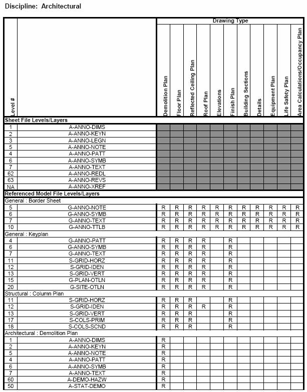
15 1. Users should note that several model files have three levels/layers reserved for demolition items. These levels/ layers are as follows with ** representing a Discipline. These levels/layers should only be used when an Existing/Demolition model file is being created. For instance, the architect or engineer will sometimes have existing as-built model files, such as Site Plans and Floor Plans from a previous project. A copy of the as-built file will be made for use in the current project. This copy is renamed to be the Existing/ Demolition Plan model file for that discipline. In order to distinguish items to be demolished from existing items that will remain, those items should be moved to the Demolition levels/layers. When the Existing/Demolition Plan model file is referenced into a new file to create the New construction items, the Demolition levels/layers would be turned off. P. REFERENCE FILES (XREFS) 1. Reference files (external references or XREFs) enable designers to share drawing information electronically, eliminating the need to exchange hard copy drawings between the design disciplines. With the use of reference files, the structural engineer need not wait for the architect to complete the architectural floor plans before beginning the structural framing plan model file. Nor does the engineer have to redraw the architect s structural walls on the structural framing plan model file. 2. Referencing electronic drawing information makes any future changes made by the architect apparent to the structural designer. This real-time access to the work of others ensures accuracy and consistency within a set of drawings and helps promote concurrent design efforts. No longer does one discipline have to wait until another discipline is nearly finished before they begin their drawings. 3. The use of reference files is a key component in the successful use of the level/layer assignments. To create either a model file or a final sheet file, multiple referenced model files may be required. The following tables should provide information on typical layer/level names as well as the relationship of the model files to each other to create individual sheet file. Page 15

16 Q. MODEL/SHEET FILE LAYER/LEVEL ASSIGNMENT AND DRAWING RELATIONSHIP TABLES Page 16
17 Page 17
18 Page 18
19 Page 19
20 Page 20
21 Page 21
22 Page 22
23 Page 23
24 Page 24
25 Page 25

26 Page 26
27 Page 27
28 Page 28
29 Page 29
30 Page 30

31 Page 31
32 Page 32
33 Page 33
34 Page 34
35 Page 35
36 Page 36
37 Page 37
38 Page 38

39 Page 39
40 Page 40
41 Page 41
42 Page 42
43 Page 43
44 Page 44
45 Page 45
46 Page 46
47 Page 47
48 Page 48

49 Page 49
50 Page 50
51 Page 51
52 Page 52

53 Page 53
54 Page 54
55 Page 55
56 Page 56
57 Page 57

58 Page 58
59 Page 59
60 Page 60
61 Page 61
62 End of Technical Requirements for Page 62
MVD MODEL FILE NAMING
 MVD MODEL FILE NAMING 7 February 2010 Electronic Drawing File Naming Convention Electronic files shall be named as recommended in Chapter 2 of the A/E/C CADD Standard. This naming convention allows for
UDS OVERVIEW Uniform Drawing System
 UDS OVERVIEW Uniform Drawing System The Construction Specifications Institute 601 Madison Street Alexandria, VA 1994 CSI began development of UDS Organization and presentation of drawing sets Organization
Section 4: Ontario Realty Corporation CAD Standards and Guidelines
 Section 4: Ontario Realty Corporation CAD Standards and Guidelines Ontario Realty Corporation 11 th Floor, Ferguson Block 77 Wellesley Street West Queen s Park Toronto, ON, M7A 2G3 August 10, 2007 Version
CHAPTER A-10 DRAWINGS
 CHAPTER A-10 DRAWINGS INDEX Revised May 2018 10.1 GENERAL 10.1.1 Purpose and Scope 10.2 APPLICABLE PUBLICATIONS 10.3 COMPUTER AIDED DESIGN (CAD) 10.3.1 CAD Requirements 10.3.2 CAD Deliverables 10.3.3 CAD
CAD Standards for LAWA Projects. CAD Standards for LAWA projects
 CAD Standards for LAWA Projects CAD Standards for LAWA projects Document History revision letter release date major changes approved by A September 2012 new version of standards B June 2014 General Review
Miami University. Physical Facilities Department. CAD Standards. April 2004
 Miami University Physical Facilities Department CAD Standards April 2004 1.0.0 OVERVIEW These standards pertain to the use, production and submittal of electronic CAD files at Miami University. They have
UNIVERSITY OF ROCHESTER DESIGN STANDARDS FEBRUARY 29, 2012
 SECTION 01950 - RECORD DRAWINGS & SPACE FLOOR PLANS 1.1 RECORD DRAWINGS MATERIAL AND FORMAT A. Definition 1. Final record drawings, or as-builts, are drawings, which are revised to reflect the changes
anual 2010 CADD esign M D
 Design Manual CADD 2010 M E T R O P O L I T A N W A S H I N G T O N A I R P O R T S A U T H O R I T Y (This Page Blank) CADD - Page 2 PREFACE THE DESIGN MANUAL As part of the ongoing design and construction
FACILITIES MANAGEMENT. AutoCAD Guidelines & Standards May 2015
 FACILITIES MANAGEMENT AutoCAD Guidelines & Standards May 2015 PLEASE NOTE: Changes in the 2015 guidelines appear in these sections; 1.1, 3.2, and 5.2. SECTION 1: General Guideline Table of Contents 1.1
U.S.A.C.E. ALBUQUERQUE DISTRICT A/E/C CADD STANDARD SUPPLEMENTAL STANDARD
 U.S.A.C.E. ALBUQUERQUE DISTRICT A/E/C CADD STANDARD SUPPLEMENTAL STANDARD (FOR USE WITH THE A/E/C CADD STANDARDS RELEASE 4.0) 24 March 2009 26 January 2012 PURPOSE AND SCOPE The purpose of this document
Dimension Below are the critical settings in AutoCAD. Other software should follow the same settings.
 8.1 Drawing Standard 8.1.1 Introduction This drawing standard applies to all building drawings being prepared for the University of Calgary (UCalgary) by external consultants or vendors and internal staff
Architectural Floor Plan Symbols
 Architectural Floor Plan Symbols The symbols below are used in architectural floor plans. Every office has their own standard, but most symbols should be similar to those shown on this page. Building Section
It is expected that this standard will evolve over time; however the use of this standard should remain consistent within individual projects.
 1.0 Introduction A computer aided design (CAD) procedure is necessary to ensure that drawings produced by and for the University are readable, understandable, of a consistent standard, and, where necessary,
CMW DELIVERABLES SPECIFICATION Version 1.0
 CMW DELIVERABLES SPECIFICATION Version 1.0 Code: CMW-CADD-STD-06 June 2012 CONTENTS 1 INTRODUCTION... 3 2 GENERAL... 3 3 GRAPHIC FORMAT... 3 4 CADD STANDARDS... 3 5 DELIVERY MEDIA AND FORMAT... 4 6 DRAWING
THIS PAGE INTENTIONALLY LEFT BLANK
 Facilities Management October 6, 2017 THIS PAGE INTENTIONALLY LEFT BLANK Page 2 of 31 CAD Guidelines and Standards Table of Contents SECTION 1: THE PURPOSE OF USING CAD DATA STANDARDS... 5 1.1 Industry
Vanderbilt University Standard Specification Revised 2/6/08
 SECTION 01 78 23 OPERATION AND MAINTENANCE DATA PART 1 GENERAL 1.01 RELATED SECTIONS A. Section 01 77 00 Closeout Procedures B. Section 01 78 39 Project Record Documents 1.02 SUMMARY A. This section provides
Stanford University-Facilities Design Guideline SECTION Plans Review Submission Guidelines
 SECTION 01 33 00 Plans Review Submission Guidelines PART 1 GENERAL 1.01 OVERVIEW A. University Plans Review Process: 1. The process by which the Designer s schematic, design development, construction documents
January, 2014 Page 1 of 5
 Part 1 General 1.1 General Instructions.1 These instructions add information to all articles of contracts with professionals..2 For each project, McGill University Facilities Operations and Development
Section Table of Contents: Section 12.0
 Section 12.0 Table of Contents: Section 12.0 Overview - Section 12.0... 12.0-3 Layers... 12.0-3 Filters... 12.0-3 Layer fields... 12.0-5 Discipline Designaters... 12.0-5 Status (Phase)... 12.0-5 Template
RIT CAD Specifications
 RIT CAD Specifications The design team shall provide RIT with Revit, AutoCAD, and PDF files that capture the construction conditions of the associated project. This document outlines requirements for submitting
PORTAGE COUNTY WATER RESOURCES DRAFTING STANDARDS. Date: January 26, 2001
 PORTAGE COUNTY WATER RESOURCES DRAFTING STANDARDS Date: January 26, 2001 Portage County Water Resources Drafting Standards. AutoCad 2000/Land Development Desktop R2 Friday, January 26, 2001 Preface: Part
State College Area School District
 State College Area School District The following is a guideline for project design submittals to the Facility Committee of the State College Area School District. During the design process the committee
The CAD Technician s Role in Office Practice and Procedure
 COMMERCIAL DRAFTING AND DETAILING 4TH EDITION JEFFERIS SOLUTIONS MANUAL Full download at: https://testbankreal.com/download/commercial-drafting-detailing-4th-editionjefferis-solutions-manual/ Chapter 2
FACILITIES CADD STANDARD
 2015 Facilities Services Division of Design and Construction CADD Department FACILITIES CADD STANDARD CAD, BIM, & GIS Standards for the University of Alaska Fairbanks The University of Alaska Fairbanks
PMA ONLINE TRAINING. Commercial Drawings. One Hour Continuing Education
 PMA ONLINE TRAINING Commercial Drawings One Hour Continuing Education PMA training disclaimer The information provided in this document is intended for use as a guideline and is not intended as, nor does
Bureau of Engineering. CADD Standards. Preface
 BOE CADD STANDARDS Preface The is committed to improving the quality of project delivery offered to all our Clients. By producing electronic design data consistently, communication among designer, owner
NORTHWESTERN UNIVERSITY PROJECT NAME JOB # ISSUED: 12/12/2018
 SECTION 01 7839 - PROJECT RECORD DOCUMENTS GENERAL 1.1 RELATED DOCUMENTS A. Drawings and general provisions of the Contract, including General and Supplementary Conditions and other Division 01 Specification
Facility Design Information (FDI) Section 1A - Project and Record Documents
 Section 1A - Project and Record Documents") (FDI) Section 1A - Project and Record Documents Version 1.02 February, 2009 SECTION 1A TABLE OF CONTENTS page Part 1 INTRODUCTION.. 5 1.01 PURPOSE AND APPLICABILITY. 5 1.02 TERMINOLOGY.. 5 1.03 CAD STANDARDS..
(FDI) Section 1A - Project and Record Documents Version 1.02 February, 2009 SECTION 1A TABLE OF CONTENTS page Part 1 INTRODUCTION.. 5 1.01 PURPOSE AND APPLICABILITY. 5 1.02 TERMINOLOGY.. 5 1.03 CAD STANDARDS..
CHAPTER 11 PRELIMINARY SITE PLAN APPROVAL PROCESS
 CHAPTER 11 PRELIMINARY SITE PLAN APPROVAL PROCESS 11.01.00 Preliminary Site Plan Approval 11.01.01 Intent and Purpose 11.01.02 Review 11.01.03 Application 11.01.04 Development Site to be Unified 11.01.05
The coordinate system and vertical datum shall be noted in the drawing in the metadata.
 Purpose This document is provided for informational purposes and to assure data compatibility and compliance for as-built drawings or vector data formats specifically for the 354th Civil Engineer Squadron
DIGITAL DATA SUBMISSION STANDARDS Procedures and Guidelines
 DIGITAL DATA SUBMISSION STANDARDS Procedures and Guidelines 2014 Citizens Wastewater of Westfield - GIS Digital Standards Table of Contents Introduction... 3 Definitions and Terms... 3 Reference Documents...
PITKIN COUNTY STANDARDS for ELECTRONIC DRAWINGS and DOCUMENTS SUBMISSION
 PITKIN COUNTY STANDARDS for ELECTRONIC DRAWINGS and DOCUMENTS SUBMISSION DOCUMENT SUBMISSION For Building Permit Submittal: Applicants bring Permit Application, Digital Drawings, and Supporting Documents
AutoCAD Standards University of California, Santa Cruz Physical Planning & Construction
 University of California, Santa Cruz Physical Planning & Construction 1. General Requirements: 1.1 Format 1.2 Ownership 2. Required Data: 2.1 Area Tabulation 2.2 Drawing Files 2.3 External References 2.4
CITY OF LOMPOC DEVELOPMENT ASSISTANCE BROCHURE ENCROACHMENT PERMITS AND PUBLIC IMPROVEMENT PLANS
 CITY OF LOMPOC DEVELOPMENT ASSISTANCE BROCHURE E-10 ENCROACHMENT PERMITS AND PUBLIC IMPROVEMENT PLANS The City of Lompoc has determined that the Engineering Division should administer and issue Encroachment
PROGRAMMING SCHEMATIC DESIGN DESIGN DEVELOPMENT CONSTRUCTION DOCUMENTS. room) Scalable bubble diagrams schedules describing programmatic
 Scalable bubble diagrams schedules describing programmatic") GENERAL SITE PROGRAMMING SCHEMATIC DESIGN DESIGN DEVELOPMENT CONSTRUCTION DOCUMENTS Scope of work narrative Building code review Description of construction Documentation on drawings as List of applicable
GENERAL SITE PROGRAMMING SCHEMATIC DESIGN DESIGN DEVELOPMENT CONSTRUCTION DOCUMENTS Scope of work narrative Building code review Description of construction Documentation on drawings as List of applicable
READING ARCHITECTURAL PLANS
 READING ARCHITECTURAL PLANS ARCHITECTURAL DRAWINGS FOR A HOUSE Architectural drawings contain information about the size, shape, and location of all parts of the house ARCHITECTURAL DRAWINGS FOR A HOUSE
ARCHITECTURE CADD Course Syllabus
 6111 E. Skelly Drive P. O. Box 477200 Tulsa, OK 74147-7200 ARCHITECTURE CADD Course Syllabus Course Number: TTC-0880 OHLAP Credit: Yes OCAS Code: 8903 Course Length: 120 Hours Career Cluster: Manufacturing
AutoCAD Drafting Standards
 Clark County Department of Aviation P.O Box 110055 Las Vegas, NV 89111-1005 McCarran International Airport AutoCAD Drafting Standards 5 April 2004 Prepared for CCDOA by Kennedy/Jenks Consultants AutoCAD
LACCD CADD STANDARDS Revision 3.1
 LACCD CADD STANDARDS Revision 3.1 Prepared By: Revised June 2, 2010 Table of Contents 1 INTRODUCTION 1 1.1 LACCD Project CADD Standards 1 1.2 Revision History 1 1.3 Software Guidelines 1 2 DRAWING REQUIREMENTS
Issue Date: August 2018 Revision: 03
 ENGINEERING CADD MANUAL Issue Date: August 2018 Revision: 03 Developed For: Metra Engineering Department 547 West Jackson Blvd. Chicago, Illinois 60661 Developed By: Chandra Mahalingam CADD System Administrator
Chapter 7 Computer-Aided Design and Drafting in Architecture 2D vs. 3D 3 Advantages/ Disadvantages
 Chapter 7 Computer-Aided Design and Drafting in Architecture 2D vs. 3D 3 Advantages/ Disadvantages What is CADD or CAD CADD- CAD- BIM- What does BIM require? Intro to CADD & BIM 1 Autodesk AutoCAD REVIT
A. Section includes administrative and procedural requirements for project record documents, including the following:
 SECTION 017839 - PROJECT RECORD DOCUMENTS PART 1 - GENERAL 1.1 RELATED DOCUMENTS A. Drawings and general provisions of the Contract, including General and Supplementary Conditions and other Division 01
BIM/VDC on TAA Projects:
 2018 Logan International Airport BIM/VDC on TAA Projects: Direct Tenant TAA Projects Third Party Development Properties Massachusetts Port Authority Capital Programs & Environmental Affairs Preface Massport
1.1 The Electronic Word Programs used for the Project Manual shall be Microsoft Word.
 DESIGN REQUIREMENTS 1. CONTRACT DOCUMENT FORMAT: 1.1 The Electronic Word Programs used for the Project Manual shall be Microsoft Word. 1.2 The Electronic Drafting Program used for the Contract Drawings
SECTION SUBMITTAL PROCEDURES
 SECTION 01330 - SUBMITTAL PROCEDURES PART 1 - GENERAL 1.1 RELATED DOCUMENTS A. Drawings and general provisions of the Contract, including General and Supplementary Conditions and other Division 1 Specification
Exhibit A Project Identification. Exhibit B Project Charter / Project Intent. Exhibit C Project Scope. Exhibit C Project Schedule
 Exhibit A Project Identification Exhibit B Project Charter / Project Intent Exhibit C Project Scope Exhibit C Project Schedule Exhibit D Project Budget Exhibit E Owner Supplied Documents Exhibit F Sample
ADDENDUM #2 September 12, 2018
 Physical Plant Services Project Management 1000 Rim Drive Phone: (970) 247-7523 Fax: (970) 247-7555 Project No. 2007-130P18 Whalen Gymnasium Expansion and Renovation for Exercise Science Request for Qualifications
Developer Design Review Submittal Requirements - SECTION 5
 Developer Design Review Submittal Requirements - SECTION 5 5.0 Developer Design Review 1.0 Procedures for Submittals - All Housing Types 1. Submittals shall be by the Guest Builder or authorized agent
Services Overview. Northeast Blueprint
 Services Overview 2D CAD Conversions Paper to CAD 2D CAD Conversions Construction Engineering / CAD Services Construction Markups Consultant Drawings Coordinated Drawings As -Builts Steel Structural Detailing
A Productivity Comparison of AutoCAD and AutoCAD Architecture Software
 AUTODCAD ARCHITECTURE A Productivity Comparison of and Software provides the best software-based design and documentation productivity for architects. This study details productivity gains over in designing
Required Supporting Information and Documentation for Historic Preservation Certification Applications
 Required Supporting Information and Documentation for Historic Preservation Certification Applications Part 1 Submittal- Evaluation of Significance Descriptive Information Describe the major features of
Chapter 6. Architectural Lines and Lettering
 Chapter 6 Architectural Lines and Lettering Drafting Introduction Universal graphic language Uses lines, symbols, dimensions, and notes to describe a structure to be built Properly drawn lines are dark,
ELECTRONIC DRAFTING GUIDELINES
 ELECTRONIC DRAFTING GUIDELINES Edition No. 6 Updated November 2016 TABLE OF CONTENTS Section Title Page 1 Definitions 3 2 Drawing Format 3 2.1 Standards & Guidelines 3 2.2 Survey Plans 4 2.3 Underground
SECTION UNDER REVIEW, SUBJECT TO FURTHER NOTICE.
 6 CAD DOCUMENTATION PROTOCOL 6.1 CAD SECTION UNDER REVIEW, SUBJECT TO FURTHER NOTICE. Introduction 6.1.1 General The purpose of this protocol is to set out conditions and requirements in relation to CAD
Interference? Verify and Analyze This!
 11/30/2005-3:00 pm - 4:30 pm Room:N. Hemispheres (Salon A2) (Dolphin) Walt Disney World Swan and Dolphin Resort Orlando, Florida David Butts - CADRE Systems Inc. ME34-1 In Autodesk Building Systems you
A/E/C CAD Standard and A/E/C Graphics Standard Frequently Asked Questions (FAQ) updated 8/9/2017
 updated 8/9/2017") A/E/C CAD Standard and A/E/C Graphics Standard Frequently Asked Questions (FAQ) updated 8/9/2017 1. Question: Why do I need a CAD Standard? Answer: The National CAD Standard (NCS) provides the following
A/E/C CAD Standard and A/E/C Graphics Standard Frequently Asked Questions (FAQ) updated 8/9/2017 1. Question: Why do I need a CAD Standard? Answer: The National CAD Standard (NCS) provides the following
Architectural Design Process
 Architectural Design Process Custom Residential A. Schematic Design Phase Pre-Design Meeting Site Analysis Site Survey Conceptual Design & Project Scope Design Program Guideline Project Team Formation
Type A. BWSC CAD Standards for Site Plans (Design and As-Built) Format. Scale. Fonts, Linetypes, Shapes
 Format. Scale. Fonts, Linetypes, Shapes") BWSC CAD Standards for Site Plans (Design and As-Built) Type A The following CAD standards are for Type A application and involve no work in Public Street, except for connection(s) to the Boston Water
BWSC CAD Standards for Site Plans (Design and As-Built) Type A The following CAD standards are for Type A application and involve no work in Public Street, except for connection(s) to the Boston Water
SECTION SUBMITTALS. A. PART A and DIVISION 1 of PART B are hereby made a part of this SECTION.
 SECTION 013300 PART 1 GENERAL 1.01 GENERAL REQUIREMENTS A. PART A and DIVISION 1 of PART B are hereby made a part of this SECTION. B. Examine all conditions as they exist at the project prior to submitting
Design Deliverables. Summary. A. Expectations for Design Deliverables:
 Design Deliverables Summary A. Expectations for Design Deliverables: The Design Team is obligated to advance and deliver the project with a professional manner and standard of care that meets the expectations
TCC/SHORE TRANSIT BUS MAINTENANCE FACILITY - PHASE II
 SECTION 013300 - SUBMITTAL PROCEDURES PART 1 - GENERAL 1.1 RELATED DOCUMENTS A. Drawings and general provisions of the Contract, including General and Supplementary Conditions and other Division 01 Specification
Owner / Architect Certification of Complete Documentation for the Additions and Remodels Conditional Approval Review
 Step 1: Request for Conditional Approval, page 1 of 5 Owner / Architect Certification of Complete Documentation for the Additions and Remodels Conditional Approval Review I,, the Property Owner, or Owner
2 The UDS is a component of the United States National CAD
 Sheet Specifications By Ronald L. Geren, AIA, CSI, CCS, CCCA, SCIP Some projects are of such a small size that for a separate project manual containing the project specifications is considered unnecessary.
BIM. e Submission Guideline Structural. Annex 1a. Recommended Process Revit 2010
 BIM e Submission Guideline Structural Annex 1a Recommended Process Revit 2010 Building and Construction Authority 5 Maxwell Road #16-00 Tower Block MND Complex Singapore 069110 www.bca.gov.sg Revision
CONSULTANT: Wantman Group, Inc SERVICE AUTHORIZATION NO. _12-03 FOR CONSULTING SERVICES CITY PROJECT NO CONSULTANT PROJECT NO.
 EXHIBIT A CONSULTING SERVICE AUTHORIZATION DATE: CONSULTANT: Wantman Group, Inc SERVICE AUTHORIZATION NO. _12-03 FOR CONSULTING SERVICES CITY P.O. NO. CITY EXPENSE CODE CITY PROJECT NO. 14-073 CONSULTANT
GRICE-TRIVERS JOINT VENTURE ARCHITECTS PAGE 1 PROJECT NO
 PAGE PROJECT NO. 0-0 0 0 0 0 0 DATE: PROJECT: GATEWAY STEM ATHLETICE FIELD ALTERATIONS GATEWAY STEM HIGH SCHOOL - ST. LOUIS PUBLIC SCHOOLS 0 MCRTEE AVENUE ST. LOUIS, MISSOURI 0 TO BID DOCUMENTS DATED DECEMBER,
NORTHWESTERN UNIVERSITY PROJECT NAME JOB # ISSUED: 03/29/2017
 SECTION 01 3300 - SUBMITTAL PROCEDURES PART 1 - GENERAL 1.1 RELATED DOCUMENTS A. Drawings and general provisions of the Contract, including General and Supplementary Conditions and other Division 01 Specification
4/21/2011. Working Drawings. Working Drawings. Working Drawings. Detail Drawings. Section Assembly. Orthographic Assembly Drawing
 Working Drawings The Working drawings provide all of the specifications for the manufacture of a design. Working Drawings It is imperative that they describe all components completely and not contain any
Autodesk Revit MEP Learning Essentials Training Course Outline
 Module 00 Revit in a Nutshell Interactive exercise on creating and documenting a basic building Module 01 Introduction to the Principles of BIM Simple Truths Behind the hype The benefits of BIM What will
Drawing Management Brain Dump
 Drawing Management Brain Dump Paul McArdle Autodesk, Inc. April 11, 2003 This brain dump is intended to shed some light on the high level design philosophy behind the Drawing Management feature and how
ARCHITECT VECTORWORKS EIGHTH EDITION TUTORIAL MANUAL BY JONATHAN PICKUP
 CH EIGHTH EDITION TUTORIAL MANUAL BY JONATHAN PICKUP A M TO R I A L T TU EC IT UA L AR ARCHITECT N HTH EDITION EIG / / / / / / / / / / / / / / / / / / / / / / / / / / / / / / / / / / / / / / / / / / /
MODEL SETUP FOR RENOVATION PROJECTS INSTRUCTIONS AND TUTORIALS
 MODEL SETUP FOR RENOVATION PROJECTS INSTRUCTIONS AND TUTORIALS WHAT S INSIDE INTRODUCTION 1 PART ONE LAYERS AND CLASSES FOR RENOVATION PROJECT 1 OVERVIEW 1 SETTING UP LAYERS AND CLASSES 1 CREATING OBJECT
Record Drawing Standards for Projects Version 2.1
 for Projects Version 2.1 Updated September 21, 2016 Department: Spatial Data Group Engineering & Maintenance 1. INTRODUCTION... 1 2. GENERAL STANDARDS... 1 2.1 Drawing Standards... 1 2.2 Digital Submission
Inserting and Creating ImagesChapter1:
 Inserting and Creating ImagesChapter1: Chapter 1 In this chapter, you learn to work with raster images, including inserting and managing existing images and creating new ones. By scanning paper drawings
Strengthened Technical-Vocational Education Program COURSE DESIGN
 COURSE DESIGN COURSE TITLE : DRAFTING TECHNOLOGY NOMINAL DURATION : 1200 HOURS QUALIFICATION LEVEL : NC II COURSE DESCRIPTION : This course is designed to enhance the knowledge, skills, and positive attitudes
Drawing Standards & Conventions for IDD
 Drawing Standards & Conventions for IDD This document consists of a set of standards that have been developed to maintain a consistency in Interior Decoration and Design students work. The standards are
Checklist for Minor Plan Modification
 Checklist for Minor Plan Modification All submittal information shall be provided to the Community Development Department. All submittal information shall be presented along with the Uniform Application,
5.7 Plan Documentation and Supporting Information.
 5.7 and Supporting Information. In any case where the and Supporting Information for a Development Plan requires the submission of a Site Plan, Overall Plan, Landscape Plan, Building Elevations, Sign Plan
The GMFI Process. Design Intent Document Preparation. Enroll in GMFI Program. Image Consultation. You are here. Design Intent Document.
 Enroll in GMFI Program Image Consultation Design Intent Document Preparation Preliminary Drawings Final Drawings Design Intent Document You are here. 1-2 Construction Documents Services performed by dealer
ADDENDUM NO. TWO. To the Plans and Specifications for: PALM COAST READINESS CENTER PALM COAST, FL For FLORIDA DEPT. OF MILITARY AFFAIRS
 ADDENDUM NO. TWO To the Plans and Specifications for: PALM COAST READINESS CENTER PALM COAST, FL For FLORIDA DEPT. OF MILITARY AFFAIRS Prepared By: ARCHITECT Bhide & Hall Architects, P.A. 1329-C Kingsley
Survey Requirements. Design Guidelines and Standards. June Office of the University Architect
 Design Guidelines and Standards Survey Requirements June 2004 Office of the University Architect Construction Management P.O. Box 210181 Cincinnati, Ohio 45221-0181 Table of Contents Survey Requirements
***************************************************************************** DRAFT UFGS- 01 XX XX (FEB 2014)
") DRAFT UFGS- 01 XX XX (FEB 2014) ------------------------ Drafting Activity: USACE UNIFIED FACILITIES GUIDE SPECIFICATION SECTION TABLE OF CONTENTS DIVISION 01 GENERAL REQUIREMENTS SECTION 01 XX XX (FEB
DRAFT UFGS- 01 XX XX (FEB 2014) ------------------------ Drafting Activity: USACE UNIFIED FACILITIES GUIDE SPECIFICATION SECTION TABLE OF CONTENTS DIVISION 01 GENERAL REQUIREMENTS SECTION 01 XX XX (FEB
LESSON 1: UNDERSTANDING CONSTRUCTION DRAWINGS
 LESSON 1: UNDERSTANDING CONSTRUCTION DRAWINGS INTRODUCTION In this lesson, you ll learn about the different types of drawings used in the construction industry, and how to read floor plans, section drawings,
CHAPTER 11 SURVEY CADD
 CHAPTER 11 SURVEY CADD Chapter Contents Sec. 11.01 Sec. 11.02 Sec. 11.03 Sec. 11.04 Sec. 11.05 Sec. 11.06 Sec. 11.07 Sec. 11.08 Sec. 11.09 Sec. 11.10 General Description of Survey File Contents of Survey
Smithsonian Facilities. CAD Guidelines December Smithsonian Facilities CAD GUIDELINES. Edit indicators:
 Smithsonian Facilities CAD Guidelines December 2017 Edit indicators: All changes from the previous version of this document, dated May 6, 2011, are highlighted with a vertical line, as shown here. December
SECTION SUBMITTAL PROCEDURES PART 1 - GENERAL 1.1 RELATED DOCUMENTS
 SECTION 01 33 00 - SUBMITTAL PROCEDURES PART 1 - GENERAL 1.1 RELATED DOCUMENTS A. Drawings and general provisions of the Contract, including General and Supplementary Conditions and other Division 01 Specification
A. Section includes administrative provisions for coordinating construction operations on Project including, but not limited to, the following:
 SECTION 01 31 00 PROJECT MANAGEMENT AND COORDINATION PART 1 GENERAL 1.1 RELATED DOCUMENTS A. Drawings and general provisions of the Contract, including General and Supplementary Conditions and other Division
SECTION SUBMITTAL PROCEDURES
 SECTION 013300 PART 1 - GENERAL 1.1 RELATED DOCUMENTS A. Drawings and general provisions of the Contract, including General and Supplementary Conditions and other Division 01 Specification Sections, apply
Certificate of Appropriateness (CoA) Checklist
 Checklist") Certificate of Appropriateness (CoA) Checklist This Checklist is intended to assist you in preparing a complete application for submittal. Occasionally, additional items may be required to complete the
Certificate of Appropriateness (CoA) Checklist This Checklist is intended to assist you in preparing a complete application for submittal. Occasionally, additional items may be required to complete the
INDEX OF SHEETS FLAMING GORGE RANGER DISTRICT OFFICE ADDITION REGION 4 INTERMOUNTAIN REGION ASHLEY NATIONAL FOREST DRAWING SHEET INDEX
 INDEX OF SHEETS SHT. DWG. SHEET TITLE GENERAL 1 G1 COVER SHEET, VICINITY MAP, PROJECT DESCRIPTION 43 A402 INTERIOR ELEVATIONS WOMENS 44 A403 INTERIOR ELEVATIONS MENS 45 A404 INTERIOR ELEVATIONS BUILDING-PLUMBING
PRELIMINARY PLAT CHECK LIST
 Name of Proposed Subdivision: The following items must be included with the initial submittal of a Preliminary Plat: Application, filled out completely Project Narrative Pre-application Conference Report
NTG Technical Drawings
 DEPARTMENT OF INFRASTRUCTURE, PLANNING AND LOGISTICS NTG Technical Drawings Part 1 Requirements for Technical Records Management Approval Sheet Title NTG Technical Drawings Part 1 Requirements for Technical
Fundamentals for building Drawing
 Fundamentals for building Drawing What is Drawing Introduction Knowledge of preparing and understanding drawing will prove to be an invaluable aid while performing their jobs effectively, efficiently.
Chief Architect X3 Training Series. Layers and Layer Sets
 Chief Architect X3 Training Series Layers and Layer Sets Save time while creating more detailed plans Why do you need Layers? Setting up Layer Lets Adding items to layers Layers and Layout Pages Layer
Symbols and Standards (Architectural CAD)
") Design and Drafting Description In this activity the teacher will give an orientation to the symbols and conventions of Architectural CAD. Industry common symbols are used for most of the fixtures and
Design and Drafting Description In this activity the teacher will give an orientation to the symbols and conventions of Architectural CAD. Industry common symbols are used for most of the fixtures and
UCCS University Hall Fire Sprinkler System Upgrade March 1, 2011 RTA SECTION SUBMITTAL PROCEDURES PART 1 - GENERAL
 SECTION 013300 - SUBMITTAL PROCEDURES PART 1 - GENERAL 1.1 RELATED DOCUMENTS A. Drawings and general provisions of the Contract, including General and Supplementary Conditions and other Division 01 Specification
Project Booklet. Structural Drafting with AutoCAD
 Project Booklet Structural Drafting with AutoCAD Introduction 1 General Setup 2 Border and Title Block 3 Drafting the Foundation Plan (Plate 1) 8 Drafting the South Elevation (Plate 2) 11 Drafting Section
MODEL SETUP FOR RENOVATION PROJECTS: INSTRUCTIONS AND TUTORIALS
 MODEL SETUP FOR RENOVATION PROJECTS: INSTRUCTIONS AND TUTORIALS TABLE OF CONTENTS INTRODUCTION 1 PART ONE LAYERS AND CLASSES FOR RENOVATION PROJECT 2 OVERVIEW 2 SETTING UP LAYERS AND CLASSES 2 CREATING
FTEV Repair Mezzanine Bldg Hurlburt Field, Florida SECTION DESIGN AFTER AWARD
 SECTION 01 10 12 DESIGN AFTER AWARD 1. DESIGN RESPONSIBILITY The Contractor shall furnish and be responsible for a complete set of design documents as called for in specification section 01 10 10 DESIGN
Mailing Address: Fax number: City: State: Zip: Property Owner: City: State: Zip: City: State: Zip:
 / Department of Community Development ARCHITECTURAL REVIEW APPLICATION 73-510 Fred Waring Drive Palm Desert California 92260 (760) 346-0611 Fax (760) 776-6417 Applicant: Telephone: Mailing Address: Fax