Shay Main Frame. Nelson Riedel Initial: 4/01/03 Last Revised06/05/2004:
|
|
|
- Briana Hopkins
- 5 years ago
- Views:
Transcription
1 Shay Main Frame Nelson Riedel Initial: 4/01/03 Last Revised06/05/2004: Let's start with a bit of history: Lima used two types of frames on the Class B (2 truck) and Class C (3 truck) shays. The sketch below from a reprint of a Lima Service Department Instruction Booklet shows the two types. Both these frames are for Class B Shays. The Class C frames are nearly identical; the major difference being that the part behind the rear truck is much shorter. (1 of 9) [6/7/2004 6:33:30 AM]


2 The upper frame is the later Girder type introduced in the period. The lower frame is the I Beam or Truss Rod type used from the beginning on the Class B and Class C Shays and is the type Kenneth used in his design. The main frame construction went much easier than the tender frame because I'd developed some expertise doing the tender frame. The following drawing is the 3-Truck Main frame provided by Kenneth. There' a half dozen more drawings for the main frame showing details such as coupler pockets, queen posts, etc. ( These drawings are available from Kenneth.) The sketch below is from a reprint of a Lima Spare Parts Book. This main frame went with the tender frame sketch shown in the tender frame note. My guess is that it's from the period. Excepting the curved rear end, it's a nearly exact match for Kenneth's drawing above. (2 of 9) [6/7/2004 6:33:30 AM]

3 If one examines the frame drawing it will be obvious that the frame is not symmetrical around the center line of the track or trucks. Recall that the engine is on the right side of the locomotive. The boiler is off center toward the left side of the locomotive to make room for the engine and to balance the weight of the engine. The boiler is centered on the side I beams with the engine attached to the outside of the right I beam. I made my main frame is exactly to Kenneth's drawing with the following exceptions: The channels were screwed together using button head cap screws (simulated rivets) rather than welded The triangle frame brackets were used instead of the flat bar frame brackets. Some cosmetic details were added such as rivet detail for bolster supports and a front sill support. The following construction sequence was used on the main frame. This is a little different from the tender frame since I knew where I was headed and had a pretty good idea of how to get there. 1. Construct the pair of bolsters Make the side I beams (two channels screwed together) and attach to bolsters. Make and install I beam truss rod details. Make and install (triangle) frame brackets 5. Make the end channels and attach to I beams. The bolsters shown on the right were assembled first. All the parts except the angle brackets were first screwed together and then silver soldered. The angle brackets were then screwed into the bolster but not silver soldered. The holes for the screws between the I beams and the bolster were drilled later using the holes in the I beams as the drilling template. The truck pivot pin holes illustrate the off center relationship between the frame and trucks. (3 of 9) [6/7/2004 6:33:30 AM]


 As you'll see later, the truss rods add nice detail.")
4 Scale I beams for the side frame pieces are not available so I beams are made by fastening two channels back-to-back. Kenneth welded his channels together. Because of nonexistent welding skills I decided to screw the channels together. Review of the Lima Drawings revealed braces from the bolsters to the I beams. I had no intention of installing those braces but the the rivets on the I beam end were used to hold the two channels of each I beam together. A clearance hole was drilled in the outer channel and the inner channel threaded for button head cap screws. There are two like the one shown below on each side of the main frame.. The truss rods looked to be a quick job until I counted up all the required parts as shown in the photo below. (When the truss rods were installed later it was discovered that 4 more of the brass nuts were required.) As you'll see later, the truss rods add nice detail. The frame brackets were made using the same technique as described for the tender. If fact, the same fixture used on the tender frame was used to fabricate the smaller brackets. These brackets were made from 20 gauge steel. The brackets and the truss rod details above took over half the main frame effort. (4 of 9) [6/7/2004 6:33:30 AM]


5 I reviewed the Lima drawing shown on the right before deciding how to fabricate the front sill and related brackets, braces, etc. The bracket between the frame and the sill channel is exactly like the bracket Kenneth shows in his drawings. I made angle brackets for each side of each I beam to attach to the upper part of the wooden sill. There is a brace from the right I beam to the back of the sill to support the sill that sticks out quite a distance from the I beam. This brace makes a nice detail to add. The photo directly below the drawing shows one of these braces on Cass No 5. The end that attaches to the I beam is different from the drawing above. Also note that the bottom of the triangle bracket is cut to provide clearance for the brace. The brace seems to be bent a bit to make room and to support the tool/storage box. My model of this area is shown in the photo below. That is the the under side of the right front. The frame was still under construction at this point and only a few screws are used to hold everything together. Button head screws (simulated rivets) will be used everywhere except into the sill where 4-40 hex head screws (simulated bolts) will be used. (5 of 9) [6/7/2004 6:33:30 AM]


6 Excepting the offset, the rear sill shown below is essentially a mirror image of the tender front sill. (6 of 9) [6/7/2004 6:33:30 AM]


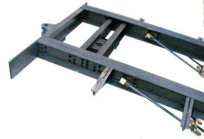
7 The following photos show completed frame after the 368 screws were installed. (7 of 9) [6/7/2004 6:33:30 AM]


8 Update 2/20/2004: Careful measurement of the frame revealed the the I beams bowed out about 1/4" midway between the two bolsters. The photo on the right shows an added cross brace to prevent the bowing. The photo is after the frame had been painted. Note that the new channel is even with the top of the (8 of 9) [6/7/2004 6:33:30 AM]

9 frame I beams. I later found that it interfered with the bottom of the boiler. A small amount of material was removed at the top center to provide clearance. The brace could have been aligned with the bottom of the I beams like the bolsters and there would have been no problem. However, I like the appearance with the cross brace in the upper position. Some of the techniques used to fabricate some of the frame parts are described in the accompanying note Main Frame Fabrication. The next task is to construct the pivot blocks and rollers that are the interface between the trucks and the frames. The construction of the brake system will complete the trucks. Shay Home NLW Home (9 of 9) [6/7/2004 6:33:30 AM]
Shay Tender Frame Fabrication
 Shay Tender Frame Fabrication Nelson Riedel Nelson@NelsonsLocomotive.com Initial:3/15/03 Last Revised: 06/05/2004 This page shows additional detail on the tender frame members and some of the processes
Shay Cab - Floor & Roof
 Shay Cab - Floor & Roof Nelson Riedel Nelson@NelsonsLocomotive.com Initial: 1/20/04 Last Revised: 06/06/2004 Cab Floor: A cab floor was made at the same time as the tender floor. I was unhappy with some
Shay Drive Shafts & Universal Fabrication
 Shay Drive Shafts & Universal Fabrication Nelson Riedel Nelson@NelsonsLocomotive.com Initial: 5/22/03 Last Revised: 06/06/2004 The following describes how I machined the universal rings and drive shafts.
Shay Truck Brakes Nelson Riedel
 Shay Truck Brakes Nelson Riedel Nelson@NelsonsLocomotive.com Initial: 4/28/03 Last Revised: 06/05/2004 Note: The truck brakes were initially grouped with the truck pivots. Later I decided to split the
Shay Boiler - Mounts & Holes
 Shay Boiler - Mounts & Holes Nelson Riedel Nelson@NelsonsLocomotive.com Initial: 11/14/03 Last Revised: 06/06/2004 The boiler was fabricated by a professional as discussed elsewhere. It was supplied with
Plumbing Part II - Hand Pump
 Plumbing Part II - Hand Pump Nelson Riedel Nelson@NelsonsLocomotive.com Initial: 7/17/03 Last Revised: 06/06/2004 The hand pump located in the tender water tank is a backup pump should the axel pump fail
Reversing Gear. Shay Reversing Gear
 Shay Nelson Riedel Nelson@NelsonsLocomotive.com Initial: 9/23/03 Last Revised: 06/05/2004 The reversing gear is another one of those pieces I've been putting off. The reason for the postponement was that
Precision Steel Car s 100 T Steel Coil Car
 Precision Steel Car s 100 T Steel Coil Car Precision Steel Car www.precisionsteelcar.com info@precisionsteelcar.com Paul Vernon: (513) 571-5739 Revised 4/30/2009 Contents of Kit Main Tube Side Frame 2
Shay - Boiler Cosmetics - Part I
 Shay - Boiler Cosmetics - Part I Nelson Riedel Nelson@NelsonsLocomotive.com Initial:3/01/04 Last Revised: 06/06/2004 I'd been dreading dealing with the exterior of the boiler because sheet metal is involved.
Note - the nose ribs and are thinner than the main ribs. These nose ribs will use a thinner rib cap than the ribs. This is per design.
 Stabilizer rev 1.2 The SE5a stabilizer is the heartbeat of the tail and is recreated like the full scale version. All tail pieces depend on the stabilizer. It uses the steel fittings, pulleys, inspection
Shay - Boiler Cosmetics - Part III
 The task here is to finish the domes. Shay - Boiler Cosmetics - Part III Nelson Riedel Nelson@NelsonsLocomotive.com Initial:4/14/04 Last Revised: 06/06/2004 http://www.nelsonslocomotive.com/shay/boiler/boilercosmeticsiii/boilercosmeticsiii.htm
INSTALLATION INSTRUCTIONS GRILLE GUARD RAM 1500 PART # 5058/5058-2
 INSTALLATION INSTRUCTIONS GRILLE GUARD PART # 5058/5058-2 PARTS LIST: Qty Description Qty Description 1 Grille Guard 8 12-1.75mm x 35mm Hex Bolts 2 Upper Frame Mounting s (for trucks without tow hooks
Installation for Full Size Polaris Ranger Crew Doors
 Installation for Full Size Polaris Ranger Crew Doors Order of Installation: Heater Doors Wiper on to Windshield Windshield Top & Back Panel Note: Most of the steps in these instructions need to be repeated
MODEL 36 Di-Acro Hand Shear
 OPERATOR S MANUAL & INSTRUCTIONS MODEL 36 Di-Acro Hand Shear Di-Acro, Incorporated PO Box 9700 Canton, Ohio 44711 3713 Progress Street N.E. Canton, Ohio 44705 330-455-1942 330-455-0220 (fax) Revised 01/02
INSTALLATION INSTRUCTIONS DODGE RAM 2 & 4WD 1500 PART # P5058
 INSTALLATION INSTRUCTIONS 2009-13 DODGE RAM 2 & 4WD 1500 PART # P5058 PARTS LIST: Qty Description Qty Description 1 Grille Guard 12 12-1.75mm Hex Nuts 2 Upper Frame Mounting s (for trucks without tow hooks
Shay Line Shafts & Universal Fabrication
 Shay Line Shafts & Universal Fabrication Nelson Riedel Nelson@NelsonsLocomotive.com Initial: 5/22/03 Last Revised: 06/05/2004 The following describes how I machined some of the parts of the line shaft.
FINNEY7 4500G May17 SR 4500G TENDER. Fig 1. Original Appearance. Side raves Sanding gear Front water fillers TIA Water treatment system
 Fig 1. Original Appearance Side raves Sanding gear Front water fillers TIA Water treatment system 4500G - 3 Fig 2. Rebuilt Condition Cut down side raves with fire iron tunnels# TIA removed and replaced
Shay Tanks Part I - Background & Fuel Tank
 Page 1 of 12 Shay Tanks Part I - Background & Fuel Tank Nelson Riedel Nelson@NelsonsLocomotive.com Initial: 7/11/03 Last Revised: Two tanks are used on the Shay, a water tank and a fuel tank. I'm planning
INSTALLATION INSTRUCTIONS 3"/4 BENT END SIDEBARS FORD F-150 SUPERCREW PART # DZ /DZ
 INSTALLATION INSTRUCTIONS 09-12 FORD F-150 SUPERCREW PART # DZ 372697/DZ 372699 PARTS LIST: 1 Driver/Left Sidebar 4 1/2 Lock Washers 1 Sidebar 4 12mm x 32mm OD x 3mm Flat Washers 1 Driver/Left Mounting
RBP-1215B-RX DODGE RAM QUAD CAB RX3
 RBP-1215B-RX3 2002-2017 DODGE RAM 15-3500 QUAD CAB RX3 Passenger side RX-3 Side Step Drill Template Passenger side rear Modular Bracket (6) L Support Brackets Driver side rear Modular Bracket Driver side
SE5a Instrument Board part 2 - rev 1.1
 SE5a Instrument Board part 2 - rev 1.1 Fuel (Petrol) Valve This valve uses two circular name plates, eight brass screws, one black plastic base, copper wire and two black plastic risers. You can pick any
Trim down the piece of casting being pointed to with the tip of the pencil in the first picture. It is only the 'inboard casting that needs to be
 1. File off the moulding pips from the wheel flanges. File the ends of the tube smooth and de-burr. Assemble the wheel sets with a drop of car engine oil on the axles. Glue the wheel sets into place. 2.
INSTALLATION INSTRUCTIONS AND PARTS LIST
 INSTALLATION INSTRUCTIONS AND PARTS LIST VEHICLE APPLICATION: MODEL 250420 (12 X 20 ) & 250423 (12 X 23 ) FRONT OR REAR MUDGUARDS 2004 AND NEWER FORD F-150 SERIES TRUCKS 1. READ INSTRUCTIONS COMPLETELY
ASSEMBLY INSTRUCTIONS FOR MAR-K BEDSIDES AND GM FLUSH TAILGATE WITH HANDLE
 ASSEMBLY INSTRUCTIONS FOR MAR-K BEDSIDES AND 41-53 GM FLUSH TAILGATE WITH HANDLE Build the box assembly according to the MAR-K assembly instructions. When installing the tailgate and latching mechanisms
Modernizing Your Opel GT: Power Rear Quarter Windows
 1 Modernizing Your Opel GT: Power Rear Quarter Windows By Wayne Torman (wayneto@msn.com) My 1973 Opel was going to be in the shop for a few weeks, and I had finished stripping my $25 wrecked 1971 in the
Bulle Clock Serial Number 57561
 Page 1 Restored Bulle Clock Bulle Clock Serial Number 57561 Page 2 Restored Bulle Clock Clock Restoration pictures by kind permission of the owner. The clock as delivered. It came without a case and the
Before returning this product to the store of purchase
 Before returning this product to the store of purchase Contact Dee Zee if you experience the following problems: Missing Parts Installation Problems/Questions Warranty Questions 1.800.779.2102 Hours of
P /8 Ring Diameter 90. Trim Ring Mounting Holes P /8. 393/16 Ring Diameter. Stud Minimum
 PARTS LIST VARIABLE Top Over Head Support Bracket 1 872070 P4000-SMR Over Head Joiner Bracket 1 VARIABLE Bottom Over Head Bracket 1 79741 P4000-SMR 4 Angled Leg 4 100-00230-14 1/4-20 x 31/2 RD. HD. MS.
Cable Tray Kit: - Cable Tray - Cable Tray Cover - Power Block Support (x2) Top Support Kit: (x2) - 2 Top Supports. Quantities are per bench
 Top Support Kit: (x2) - 2 Top Supports. Quantities are per bench") Parts Included (per back to back bench) Column Kit: (x2) - 1 LH & 1 RH Column - Control Box - Hand Switch Cable Tray Kit: - Cable Tray - Cable Tray Cover - Power Block Support (x2) Depth Support Kit: -
Parts Included (per back to back bench) Column Kit: (x2) - 1 LH & 1 RH Column - Control Box - Hand Switch Cable Tray Kit: - Cable Tray - Cable Tray Cover - Power Block Support (x2) Depth Support Kit: -
BSM, GSM & GSS. Joint Kit Instruction. (Modified for IMPACT) (NSF Certified) Curved Glass Fresh Meat Delicatessen and Seafood Merchandisers
 (NSF Certified) Curved Glass Fresh Meat Delicatessen and Seafood Merchandisers") BSM, GSM & GSS Joint Kit Instruction (Modified for IMPACT) (NSF Certified) Curved Glass Fresh Meat Delicatessen and Seafood Merchandisers February, 1999 JOINT ASSEMBLY PARTS LIST Item Quantity Description
BSM, GSM & GSS Joint Kit Instruction (Modified for IMPACT) (NSF Certified) Curved Glass Fresh Meat Delicatessen and Seafood Merchandisers February, 1999 JOINT ASSEMBLY PARTS LIST Item Quantity Description
IMPORTANT: PLEASE RETAIN THIS INSTRUCTION MANUAL FOR FUTURE REFERENCE
 IMPORTANT: PLEASE RETAIN THIS INSTRUCTION MANUAL FOR FUTURE REFERENCE 005-07 Cadillac STS Classic 3D Z, Classic Dual Weave, Classic Mesh & Classic Black Mesh Grilles B 7 HR 3 STS Classic 3D Z Grille Part
WOLF LOOM DOUBLE BACK BEAM
 WOLF LOOM DOUBLE BACK BEAM Assembly Instructions Find out more at schachtspindle.com Schacht Spindle Company 6101 Ben Place Boulder, CO 80301 p. 303.442.3212 f. 303.447.9273 2017 Schacht Spindle Company,
Continue gluing the remaining top parts ensuring the angled piece is glued well. Set aside and let dry. See photo below
 Radiator rev 1.1 The SE5a s radiator is one of the most recognized radiators in WW1. It is one of the components that defines the SE5a. The original SE5a has seen multiple radiator designs used during
INSTALLATION INSTRUCTIONS FORD F-100 INDEPENDENT FRONT SUSPENSION
 INSTALLATION INSTRUCTIONS 65-79 FORD F-100 INDEPENDENT FRONT SUSPENSION Please read these instructions completely before starting your installation. Assemble suspension on vehicle before powder-coating
BILLET SUICIDE HINGE INSTALL INSTRUCTIONS
 BILLET SUICIDE HINGE INSTALL INSTRUCTIONS Note Before Installing Installing suicide hinges is a very involved project. These instructions are general in nature because every car and every install will
Note: This assembly instruction will cover all configurations of Alloy adjustable height double bases.
 Note: This assembly instruction will cover all configurations of adjustable height double bases. 1 Screw in the provided adjustable glides into each leg as shown in Figure A. Two glides per leg. Figure
Instructions: Bethlehem 70 ton Riveted Gondola Kit
 Instructions: Bethlehem 70 ton Riveted Gondola Kit Kit number 10900 01 Steel Floor or 10900 02 Wood Floor 8/2012 Parts included in this kit: 95004 01 Plastic Part Body Shell (either steel or wood floor
FINNEY7 SR 5500G TENDER IN ORIGINAL CONDITION
 IN ORIGINAL CONDITION Fig 1. Original Appearance Side raves Sanding gear TIA Water treatment system 5500G - 3 5500G TENDER IN REBUILT CONDITION Fig 2. Rebuilt Condition Cut down side raves with fire iron
1949 to 1954 Chevrolet Dual Master Cylinder Conversion
 1949 to 1954 Chevrolet Dual Master Cylinder Conversion This document is a one stop shop to getting your brake system updated on your old Chevy. Whether you re going with a disc conversion or just sticking
ASSEMBLY & INSTALLATION GUIDE
 ASSEMBLY & INSTALLATION GUIDE APPLICATION GM Truck (Full-size Trucks) PART # 74805-00A (Silver) 74805-0A(Black) INSTALLATION TIME Hour SKILL LEVEL 2 3 4 = Easy TOOLS REQUIRED Phillips screw driver Torx
MLS MasterClass 2002
 MLS MasterClass 2002 Build a 2-6-6T / 0-6-6T Mason Bogie An Adventure in 1:20.3 By Doc Watson Chapter 6 - A Laser Cut Styrene 6-Wheel Rear Truck BY Bronson-Tate Architectural Models Construction - Supplement
INSTALLATION INSTRUCTIONS GRILLE GUARD 09-ON DODGE RAM PART #
 INSTALLATION INSTRUCTIONS GRILLE GUARD 09-ON DODGE RAM PART # PARTS LIST: Qty Description Qty Description 1 Grille Guard 8 12-1.75mm x 35mm Hex Bolts 2 Brackets (for trucks without 22 12mm x 30.1mm OD
Sheet Metal Brake Plans for a 6' Sheet Metal Brake
 Sheet Metal Brake Plans for a 6' Sheet Metal Brake,1752'8&7,21 Thank you for purchasing the sheet metal brake plans. The plans include a complete list of material needed and easy to follow steps to build
1. Underframe/Tank Bottom
 1. Underframe/Tank Bottom The construction process for the Class X tank cars is a little different as there is no true underframe. Instead we will use the tank bottom as part of the underframe, attaching
A Portable, Human-Powered Lathe Designed and Built by Scott Lewis Illustrations by David Heim
 Tailstock Toolrest and banjo Drive belt guard Headstock post Headstock spindle Page 1 Metric dimensions Tailstock post Drive belt tensioner Drive belt and flywheel Chair Bicycle pedals, sprockets, and
VINYL CLASSIC FREESTANDING PERGOLA ASSEMBLY INSTRUCTIONS
 P a g e 1 VINYL CLASSIC FREESTANDING PERGOLA ASSEMBLY INSTRUCTIONS Shown: 8' x 12' Vinyl Classic Pergola with 12" Top and Main Runner Spacing The design of this pergola is based on all posts being installed
INSTALLATION INSTRUCTIONS
 INSTALLATION INSTRUCTIONS SNYPER TUBULAR FENDERS APPLICATION: 2007-2017 Jeep Wrangler JK PART NUMBER: 62-1005, 62-1015 ITEM QUANTITY DESCRIPTION TOOLS NEEDED 1,2 2 FRONT FENDERS, DRIVER (1) AND PASSENGER
WPS crew Doors Installation instructions
 WPS-132-133 crew Doors Installation instructions ORDER OF INSTALLATION FOR A COMPLETE ENCLOSURE OF A CREW WPS (Weather Protection System) IS AS FOLLOWS: 1. Heater 2. Rear Thresholds - Right Hand & Left
Precision Steel Car s 40 Ft. Stock Car
 Precision Steel Car s 40 Ft. Stock Car Precision Steel Car Website: www.precisionsteelcar.com E-mail: info@precisionsteelcar.com Revised 12/3/2018 Paul Vernon: (513) 571-5739 PSC 40 ft. Stock Car Kit:
INSTALLATION GUIDE FTX FLOOR Ford Transit ( 148" Extended Wheelbase )
") INSTALLATION GUIDE 6540-FTX FLOOR Ford Transit ( 148" Extended Wheelbase ) QUICK START GUIDE Phase 1 - Assembly q 1.1 Setup... 3-4 Phase 2 - Installation q 2.1 Install Preparation... q 2.2 Floor Installation...
INSTALLATION GUIDE 6540-FTX FLOOR Ford Transit ( 148" Extended Wheelbase ) QUICK START GUIDE Phase 1 - Assembly q 1.1 Setup... 3-4 Phase 2 - Installation q 2.1 Install Preparation... q 2.2 Floor Installation...
GRAND PIANO HARDWARE AND ACCESSORIES
 GRAND PIANO HARDWARE AND ACCESSORIES LID SUPPORT CUP No. 938 - Solid brass. Each No. 938N - Nickel plated. Each GRAND RAIL PROP NUTS Slotted grand rail prop nuts for replacement. Solid Brass. No. 925 -
Shay Truck Machining I - RH Journal Box
 Shay Truck Machining I - RH Journal Box Nelson Riedel Nelson@NelsonsLocomoitive.com Initial: 2/28/03 Last Revised: 06/05/2004 I mentioned elsewhere that my limited machining skills are self taught. This
Additional Parts List:
 THE TIME MACHINE Additional Parts List: In addition to the cast resin parts enclosed in this kit, there should also be a plastic bag containing the following items needed to complete your time machine
INSTALLING YOUR NEW SPRING LIFT ARM KIT
 INSTALLING YOUR NEW SPRING LIFT ARM KIT 1. Measure the distance that the roof is to be raised. [If your lift system is completely non-functional, you will need to calculate or estimate this distance as
CAB END BEDTRAX (SIDE VIEW)
") Supplied Hardware: (8-14) 1/4-20 Allen head bolts, (12-18) UHMW mount blocks, (4) D-ring tie downs Tools Needed: Allen head wrench GET TO IT. INSTALLATION INSTRUCTIONS STEP 1. INSERT (2) MOUNT BLOCKS INTO
Supplied Hardware: (8-14) 1/4-20 Allen head bolts, (12-18) UHMW mount blocks, (4) D-ring tie downs Tools Needed: Allen head wrench GET TO IT. INSTALLATION INSTRUCTIONS STEP 1. INSERT (2) MOUNT BLOCKS INTO
JK Rear Inner Fenders
 INSTALLATION INSTRUCTIONS INST-17-05-080_A JK Rear Inner Fenders IMPORTANT: Thank you for purchasing this Poison Spyder product. Please read through this entire document before proceeding with installation.
WOLF PUP LOOM TM & WOLF PUP LT LOOM TM
 WOLF PUP LOOM TM & WOLF PUP LT LOOM TM Assembly Instructions FL3000 FL3006 FL3009 WOLF PUP WOLF PUP LT Find out more at schachtspindle.com Schacht Spindle Company 6101 Ben Place Boulder, CO 80301 p. 303.442.3212
Why are we giving this guidebook as a FREE download?
 Construction Guide Queen, Double & Twin Vertical 1 Note: This guide covers the construction steps for all 3 sizes of the vertical wall mount Easy DIY Murphy beds, Queen, Double and Twin. The construction
Lid, Floor Monument and Two Installation Fixtures. Floor Monument Installed with Lid On and Off
 Monumentation Drilling Specifications: Floor Monuments: - Floor is drilled using 1 3/4" core drill bit to a depth of 2 with a Hilti rotary hammer drill - Quikrete is used to set monuments into the floor
BOX-115 Club Car Precedent Utility Box Mounting Kit Installation Instructions
 BOX-115 Club Car Precedent Utility Box Mounting Kit Installation Instructions Contents of BOX-115 Utility Box Mounting Kit: a (1 ea.) Utility Box Support Frame, Passenger Side b (1 ea.) Utility Box Support
Jass.Performance Low Profiles Installation Manual
 Jass.Performance Low Profiles Installation Manual What is in the box: 2x Adapter Frame 2x Outer Panels 2x Inner Panels Pushrod, Ball Joints & Brackets 2x Hella Headlights 6x Springs 4x M6x25 Cross Head
Installation Instructions
 DODGE 16K Industry Standard Rail Custom Mounting Kit #2728 Gross Trailer Weight (Maximum)...16,000 lbs. Vertical Load Weight (Max. Pin Weight)...4,000 lbs. SYSTEM TOW CAPACITY Please note, in order to
BOX-118 E-Z-Go TXT Utility Box Mounting Kit Installation Instructions
 BOX-118 E-Z-Go TXT Utility Box Mounting Kit Installation Instructions Contents of BOX-118 Utility Box Mounting Kit: a (1 ea.) Utility Box Support Frame, Driver Side b (1 ea.) Utility Box Support Frame,
No. 412, 414, 416 Operations Manual
 No. 412, 414, 416 Operations Manual CARE: Occasional oiling of moving parts with machine oil will ease operation and extend the life of the brake. Occasionally check and tighten the lower beam bracket
Part# 85200, 86200, 85095, 86095, TC200,TT200,TC095,TT095
 Part# 85200, 86200, 85095, 86095, TC200,TT200,TC095,TT095 Bag Hardware: (8) 5/16 x 1 ½ Allen flat head (14) 3/8 x 1 Hex bolt G5 (2) ½ x 2 ½ Hex Bolt G5 (6) 5/16 flange nuts (14) 3/8 flange nuts (2) ½ stove
FLIP TARP SINGLE & DOUBLE UNDERBODY TRAILERS
 1-800-248-7717 1002 N. 15th Street, Middlesboro, KY 40965 FLIP TARP SINGLE & DOUBLE UNDERBODY TRAILERS INSTALLATION INSTRUCTIONS Congratulations on your purchase of a Mountain Flip Tarp Trailer system.
1. Remove factory stock bump stop and mount from the frame.
 1. Disconnect the negative terminal on the battery. With the vehicle on level ground and the emergency brake set, block the front tires. 2. Jack up the rear of the vehicle and support the frame rails with
TYGER GUARD. Parts List BEFORE INSTALLATION WARNING TG-GD6D /7. Tyger Guard. Tube Brackets (Bull Bar) passenger or driver side
 passenger or driver side") TYGER GUARD TM BEFORE INSTALLATION TG-GD6D60068 READ INSTRUCTIONS CAREFULLY BEFORE STARTING INSTALLATION. REMOVE CONTENTS FROM BOX AND VERIFY ALL PARTS ARE PRESENT. ASSISTANCE IS RECOMMENDED. CUTTING IS
TYGER GUARD TM BEFORE INSTALLATION TG-GD6D60068 READ INSTRUCTIONS CAREFULLY BEFORE STARTING INSTALLATION. REMOVE CONTENTS FROM BOX AND VERIFY ALL PARTS ARE PRESENT. ASSISTANCE IS RECOMMENDED. CUTTING IS
GRILLE GUARD SPRINTER VAN (EXCLUDES X4) INCLUDES MERCEDES, FREIGHTLINER AND DODGE PARTS LIST:
 INCLUDES MERCEDES, FREIGHTLINER AND DODGE PARTS LIST:") PARTS LIST: 1 Grille Guard 8 12mm Hex Nuts 1 Driver/Left Side Frame Mounting Bracket 2 10-1.50mm x 25mm Button Head Bolts 1 Passenger/Right Side Frame Mounting Bracket 4 10mm x 20mm OD x 2mm Flat Washers
PARTS LIST: 1 Grille Guard 8 12mm Hex Nuts 1 Driver/Left Side Frame Mounting Bracket 2 10-1.50mm x 25mm Button Head Bolts 1 Passenger/Right Side Frame Mounting Bracket 4 10mm x 20mm OD x 2mm Flat Washers
Clayton Off Road COR COR COR
 Clayton Off Road COR-4806011 COR-4806021 COR-4806031 JEEP GRAND CHEROKEE WJ LONG ARM UPGRADE KITS (1999-2004 WJ) NOTES: This product requires general welding, fabrication and automotive mechanic skills.
MMD Convertible Styling Bar Customer Installation Guide
 MMD Convertible Styling Bar Customer Installation Guide TOOLS REQUIRED/RECOMMENDED: Electric Drill 1 Forstner Bit (Hole Saw) 1 3/8 Hole Saw (manual calls for 1 ¾ ) 1/8, 3/8 & ¾ Drill Bits Rivet Gun Trim
20 ORE CAR INSTRUCTIONS. Kit )rv \M TAURUS PRODUCTS P.0. BOX 6534 ORANGECA m WeWWW. Dronerty efi N456 Inc.
rv \M TAURUS PRODUCTS P.0. BOX 6534 ORANGECA m WeWWW. Dronerty efi N456 Inc.") 20 ORE CAR Kit 3305 - INSTRUCTIONS TAURUS PRODUCTS )rv \M P.0. BOX 6534 ORANGECA. 92667 m WeWWW Dronerty efi N456 Inc. Thank you for selecting this TAURUS PRODUCTS kit. We sincerely hope that you will
20 ORE CAR Kit 3305 - INSTRUCTIONS TAURUS PRODUCTS )rv \M P.0. BOX 6534 ORANGECA. 92667 m WeWWW Dronerty efi N456 Inc. Thank you for selecting this TAURUS PRODUCTS kit. We sincerely hope that you will
Interior CHAPTER 21. Phantom Roadster Instruction Manual 273
 CHAPTER 21 Interior When you get to this chapter you are now starting on the finish that will make your car one that will be complete your hard work. This chapter will cover the installation of the door
INSTALLATION INSTRUCTIONS PART#:17A045200MSS\17A045200MA MODULAR GRILL GUARD FOR FORD SUPER DUTY F250/F
 INSTALLATION INSTRUCTIONS PART#:17A045200MSS\17A045200MA MODULAR GRILL GUARD FOR FORD SUPER DUTY F250/F350 08-09 1 guard, center section 1 brush guard, left side 1 brush guard, right side 1 wire guard
PRODUCT INFORMATION MANUAL SECTION: 16 FIXED METAL AWNINGS FIXED METAL AWNINGS
 FIXED METAL AWNINGS Fixed Metal Awnings BAHAMA Maximum Width Minimum Width Minimum projection Minimum Drop TS - Truss Support Maximum Overhang Minimum Overhang Unlimited 500mm TS=1601mm PS=2847mm PS=
FORD Ford Aerostar Van (extended only) Ford Bronco Ford Bronco II Ford Ranger P/U (except Flareside)
 Ford Bronco Ford Bronco II Ford Ranger P/U (except Flareside)") June 2007 INSTALLATION INSTRUCTIONS Rev. 1 MODEL NO. 82650 APPLICATION: CHEVROLET/GMC 1992-94 Chevrolet Blazer (full size) 1996-04 Chevrolet/GMC Van (full size) 1983-04 Chevrolet S-10 P/U (short bed, EXC
June 2007 INSTALLATION INSTRUCTIONS Rev. 1 MODEL NO. 82650 APPLICATION: CHEVROLET/GMC 1992-94 Chevrolet Blazer (full size) 1996-04 Chevrolet/GMC Van (full size) 1983-04 Chevrolet S-10 P/U (short bed, EXC
Bow Press - Homemade
 Bow Press - Homemade By Midlife Crisis These plans were largely (almost all) based on plans from Devin Smith posted at: http://www.bowzone.ca/modules.php?op=modload&name=news&file=article&sid=122 I modified
RH-412 STEEL DOORS INSTALLATION INSTRUCTIONS
 RH-412 STEEL DOORS INSTALLATION INSTRUCTIONS By following the steps outlined below, the assembly, installation and adjustment of the steel doors, will be a simple process. Let s start with the Driver Side.
MIDLAND RAILWAY JOHNSON 6-WHEEL 3,250g TENDER
 MIDLAND RAILWAY JOHNSON 6-WHEEL 3,250g TENDER These tenders were built in large numbers together with others of varying water capacity. During their life some were fitted with water pickup apparatus and
PROVEN WORLDWIDE SNORKEL FOR CHEVY COLORADO NEW PRODUCT
 AEV30272AC Last Updated: 10/09/18 PROVEN WORLDWIDE SNORKEL FOR CHEVY COLORADO NEW PRODUCT Please visit www.aev-conversions.com to view the most current installation guide for this product. This is a new
Project 8.1a Model A Button Maker
 Page 1 of 16 Project 8.1a Model A Button Maker Introduction Interpreting dimensioned drawings is an important engineering skill. Using drawings to create a computer model of a part is also important. You
CONCEPT MODELS INSTRUCTIONS FOR THE KASGRO KRL SPECIAL DEPRESSED CENTER FLAT CARS El Toro Way Stockton, CA 95210
 CONCEPT MODELS Web Address: http://www.con-sys.com Email: concept_models@con-sys.com 8810 El Toro Way Stockton, CA 95210 INSTRUCTIONS FOR THE KASGRO KRL 204000-2 SPECIAL DEPRESSED CENTER FLAT CARS 2 CONCEPT
Section A December 2009
 Section A ELEVATOR December 2009 1A Index 1. 47-011053-004 Deflection Chain Gear w/bearing Complete 2. 11-051772-001 Lockwasher (12 mm) 3. 47-011130-004 Bearing Bolt 4. 47-011245-003 Lower Chain Guide
Written By Phil (T90) for Team MudRhino
 for Team MudRhino") Rock Sliders Written By Phil (T90) for Team MudRhino WWW.MUDRHINO.COM.AU The most vulnerable cosmetic part of any vehicle while off-roading is the door sills (rocker panels), located just under the doors.
Rock Sliders Written By Phil (T90) for Team MudRhino WWW.MUDRHINO.COM.AU The most vulnerable cosmetic part of any vehicle while off-roading is the door sills (rocker panels), located just under the doors.
Ford Pick Up Rear leaf Spring Kit Installation Instructions
 1948-1956 Ford Pick Up Rear leaf Spring Kit Installation Instructions 1-800-984-6259 www.totalcostinvolved.com Parts 48 inch leaf (2) springs (4) U-bolts 3/8-24 x l 1/4bolts (16) & nuts (2) 1/2-20 x 4
Brassmasters
 Brassmasters www.brassmasters.co.uk Scale Models LONDON & NORTH EASTERN RAILWAY 4200 GALLON GROUP STANDARD TENDER KIT Designed by Martin Finney 4MM SCALE OO - EM - P4 INSTRUCTIONS AND PROTOTYPE NOTES PO
INTRODUCTION. EqunioxRoof.com. Pro Tip
 INSTALLATION MANUAL INTRODUCTION The Equinox Louvered Roof System is designed to be installed in an aluminum frame. All these sections are 1/8" thick extruded aluminum. All engineering for this system
DTU 26 LOW-COST STEEL & WOOD OX CART. Animal Cart Programme D T U
 DTU D T U Animal Cart Programme TECHNICAL 26 LOW-COST STEEL & WOOD OX CART RELEASE Development Technology Unit, Department of Engineering, University of Warwick, Coventry, CV4 7AL UK, tel: +44 (0)1203
FRONT AND REAR HOOD ASSEMBLY (GRAIN CART) REF PART# DESCRIPTION QTY RETAIL
 REF PART# DESCRIPTION QTY RETAIL") FRONT AND REAR HOOD ASSEMBLY (GRAIN CART) 1 0001-014311 GRAIN CART STEEL FRONT HOOD 1 1A 0001-014313 GRAIN CART 5" OFFSET STEEL FRONT HOOD 1 2 0001-014312 GRAIN CART STEEL REAR HOOD 1 N/A 0001-014901 GRAIN
FRONT AND REAR HOOD ASSEMBLY (GRAIN CART) 1 0001-014311 GRAIN CART STEEL FRONT HOOD 1 1A 0001-014313 GRAIN CART 5" OFFSET STEEL FRONT HOOD 1 2 0001-014312 GRAIN CART STEEL REAR HOOD 1 N/A 0001-014901 GRAIN
The Universal Table Saw Sled
 The Universal Table Saw Sled Do Precision Work Even with Inexpensive Table Saws! Table saw blades always tend to move the wood while the cut is being made. This is why it's so difficult to get accurate
STEAM AND THINGS 16MM SCALE VR NBC ETCHED BRASS KIT CONSTRUCTION
 STEAM AND THINGS 16MM SCALE VR NBC ETCHED BRASS KIT CONSTRUCTION SUPPLEMENTARY NOTES Some additional tools are recommended: Due to the thickness of the brass and the long lengths an 18 bending brake is
Hiniker Company th St. P.O. Box 3407 Mankato, MN VEHICLE INSTALLATION INSTRUCTIONS FOR: CHEV/GMC 4x4: K1500 SILVERADO/SIERRA
 VEHICLE INSTALLATION INSTRUCTIONS FOR: CHEV/GMC x: 007 03 K500 SILVERADO/SIERRA Page of 5 Hiniker Company 58766 0th St. P.O. Box 307 Mankato, MN 5600 INSTRUCTION SHEET NO: 505 Rev. A August 0, 03 IMPORTANT:
TOOL LIST FOR TAILGATE HIDDEN LATCH & LINK ASSY FOR FORD FLARESIDE TRUCKS
 TOOL LIST FOR TAILGATE HIDDEN LATCH & LINK ASSY FOR 53-87 FORD FLARESIDE TRUCKS Vise Grip Clamps C-clamps Sharpie Marker Ball Peen Hammer Center Punch 3/8 or 1/2 Drill 5/32, 7/32, 9/32, and 3/8 Drill Bits
IDR assembly instructions:
 IDR assembly instructions: Required Tools: 2 X 12mm Open End Wrench 14mm open end wrench #2 Phillips Head Screw Driver (Drill with adjustable torque clutch recommended) 8mm nut driver (Supplied in IDR-AK)
TOOLS REQUIRED Metal Wood Wood and Metal Screws. #16 Drill #12-24 Tap. 1/8 Drill
 DEVICES COVERED IN THIS DOCUMENT: 4700S Surface Vertical Rod Device 4700SF Fire Exit Surface Vertical Rod Device TOOLS REQUIRED Metal Wood Wood and Metal Screws Sex Bolts #7 Drill ¼ -20 Tap #16 Drill #12-24
Installation Instructions Kit, Base Rail Bracket Part # 31413
 Installation Instructions Kit, Base Rail Bracket Part # 31413 Dealer / Installer: Provide a copy of these Instructions to the end user of this product. These Instructions provide important operating and
Viewing the Ryca Motors CS-1 Build Video series at youtube.com/rycamotors is highly recommended before beginning the following assembly process.
 RYCA CS-1 ASSEMBLY GUIDE [The CS-1 installation guides should be used as supplements to the videos found on our Youtube Channel. There is no strict order to the build process, but it is highly recommended
-1- Coach Instructions.
 -1- Coach Instructions. Insert the bogie pivot pins through the bottom of the coach body ensuring the dimples fit into the recesses. Glue the.06 x.25 short strips each side of the pivot head, bridge the
INSTALLATION INSTRUCTIONS FOR FRONT CASTING DECK RAIL Ranger
 INSTALLATION INSTRUCTIONS FOR FRONT CASTING DECK RAIL Ranger TOOLS REQUIRED FOR INSTALLATION: Drill motor, (1) 5/16 inch drill bit, (1) 13/64 drill bit, (1) 3/16 inch hex wrench (1) 3/32 inch hex wrench.
BIFOLD FUTON FRAME TRINITY ARM. Seat Rails and Slats x 1. *Note: Use 4pc of 100mm Bolts and 4pc of 60mm Bolts to attach the arms to the Stretchers.
 1A Parts in this box. 2pc with extra holes 2pc with extra holes & plastic stoppers Arms x 2 Back Rails and Slats x 1 Full Size: Slat Supports x 6 3pc are longer for the Back deck Back Side Rails x 2 Seat