1. Underframe/Tank Bottom
|
|
|
- Damon Heath
- 5 years ago
- Views:
Transcription


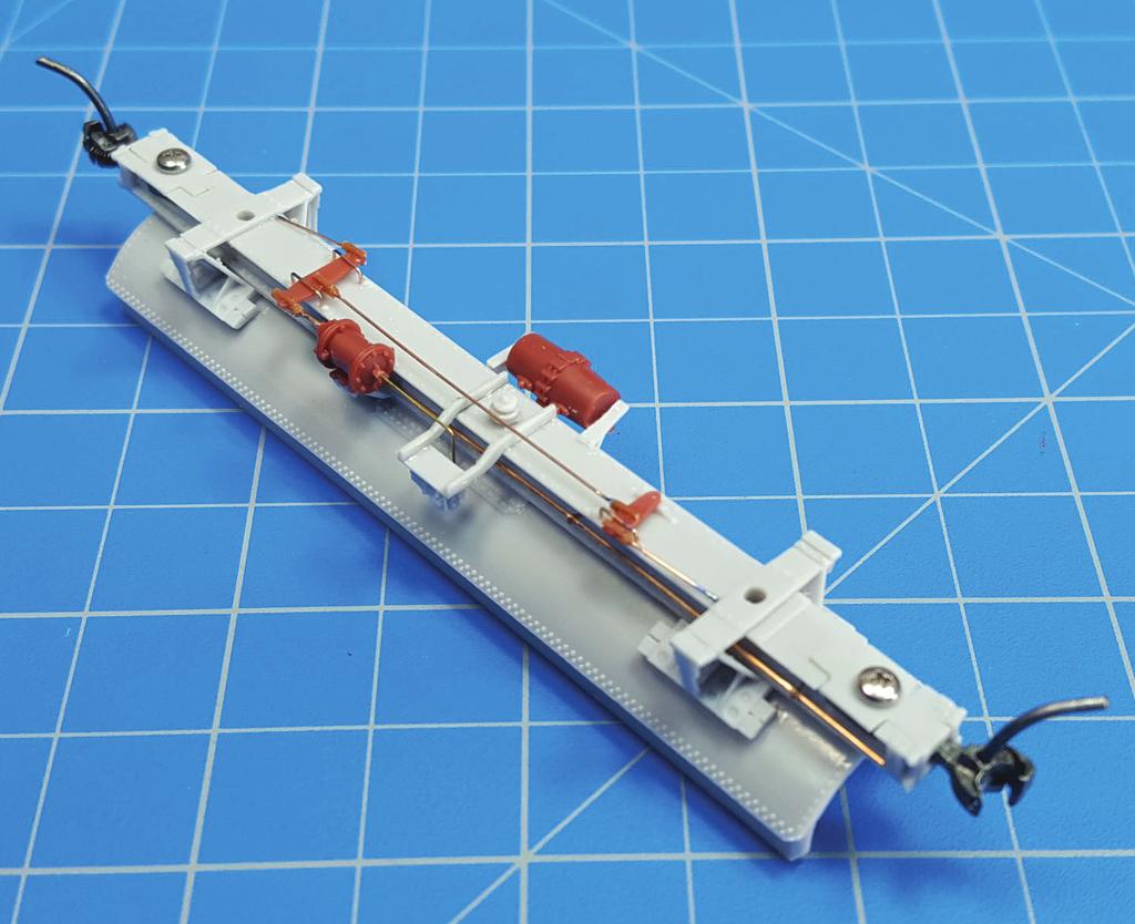
1 1. Underframe/Tank Bottom The construction process for the Class X tank cars is a little different as there is no true underframe. Instead we will use the tank bottom as part of the underframe, attaching the bottom to the tank top towards the end of construction. Note that there is a B or brake end to the centersill. The B end is the longer section from the hole in the frame for the tank drain (Photo 1). Before starting construction please consult the drawings and photos on the website to help with the location of various underframe and tank details. a. First fit the coupler pocket covers to the centersill. Sand the back surface of the covers down until the cover is flush with the bottom of the centersill. Drill and tap couplers pockets for 1-72 screws. The pockets are made to hold a Kadee #58 semi-scale coupler (not supplied in kit) without the centering spring. Install the couplers securing with 1-72 screws (not supplied in kit) (Photos 1, 2). b. Clean the interior cavities of the top and bottom tank sections to insure a good fit. c. Add the desired weight. I like using thin lead sheet from Mc- Master-Carr as it s easy to cut and form. I also 1 2


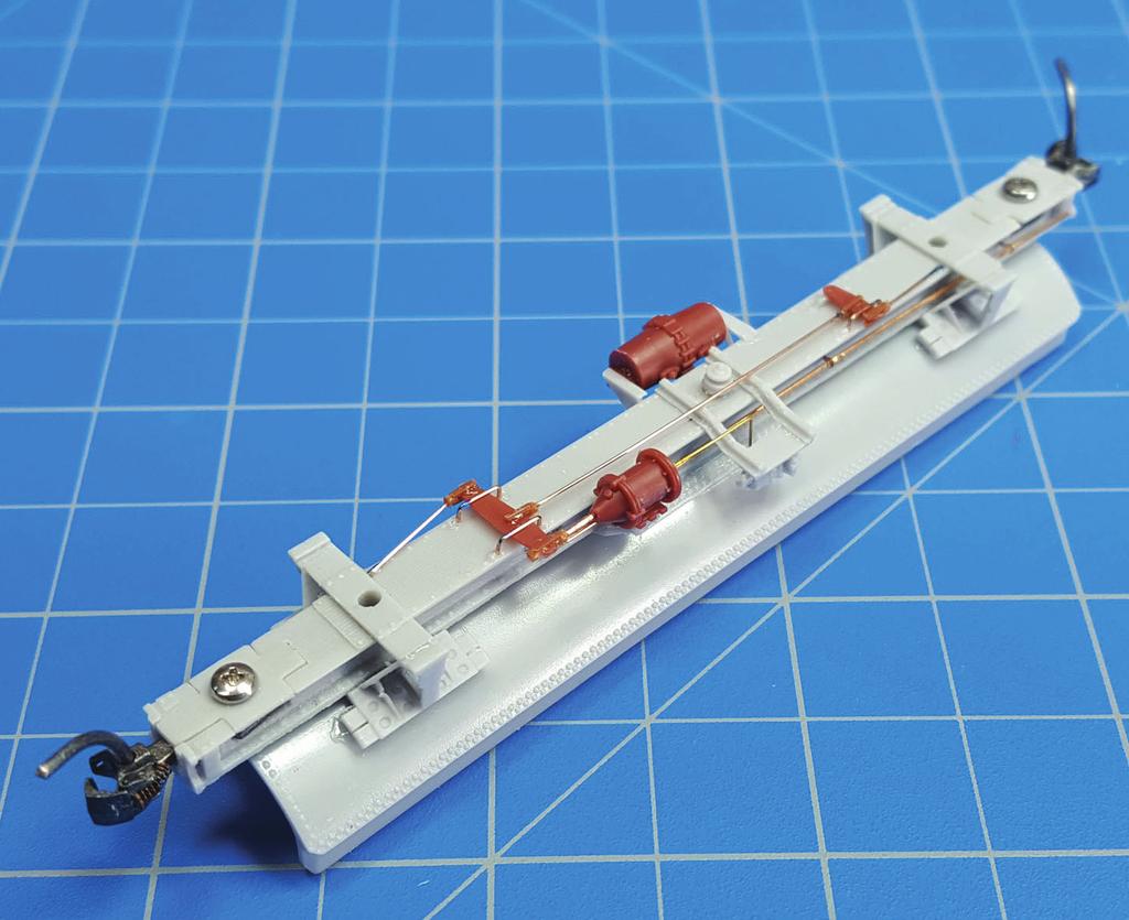
2 don t trust the glue joint between the weight material and resin so a styrene frame is built around the weight to ensure it doesn t rattle if it becomes lose. Keep the weight away from the truck screws so that the frame can be connected later to the tank. d. Remove the webs in the bolster castings to open up this area and remove the file spot and gates from the top of the centersill. Attach the bottom bolster plate to the bottom of the centersill. There are notches that these plates fit into in the centersill. There is a top and bottom to the plates. The top has notches at the ends for the bolster castings to fit into (see prototype plans) (Photos 1, 2). Attach the bolster castings to the centersill and the bolster plates (Photos 1-7). When dry, use a dowel rod or tube the same diameter as the tank being installed with sandpaper attached to curve the top of the bolster castings to fit the tank. Cover the top of the frame with masking tape to save the rivets. Note that there wasn t much clearance between the bottom of the tank and the top of the frame, only 2. e. Some cars we noted had the trainline going up and over the centersill. Most though had the trainline going through the centersill. Check prototype photos for the car you re modeling. For those cars 3 4
. When new, these cars were equipped with a K brake system which was later changed to an AB style.")
 (Photos 6, 8, 11).")
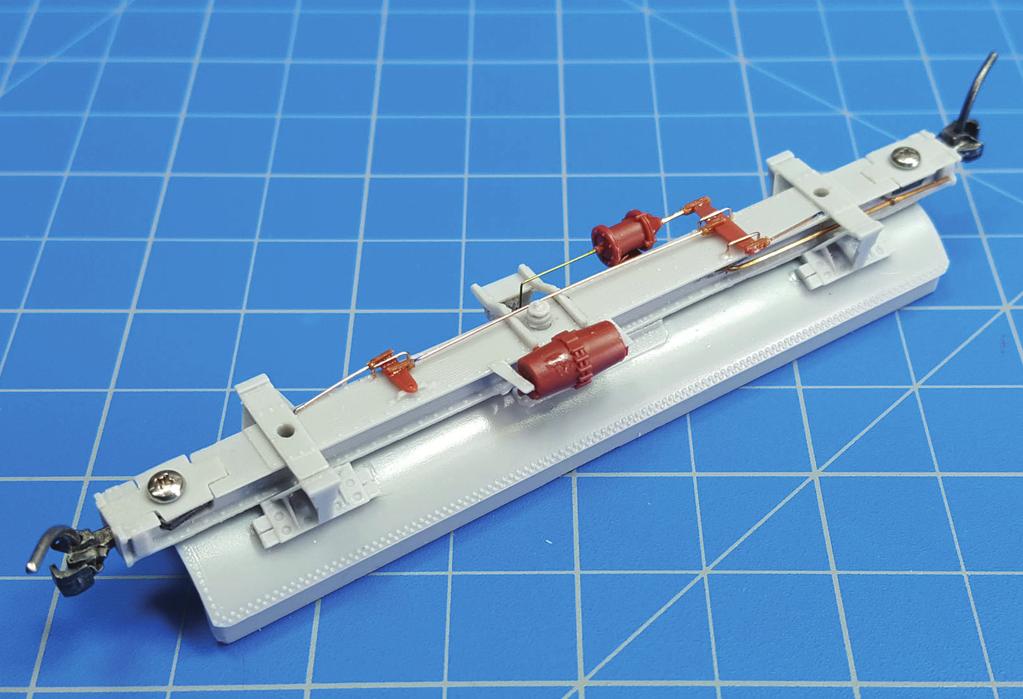
3 that had the line going through the frame, drill a #74 hole just ahead of the brake cylinder, centered in the frame on either side of the frame. Again check the prototype photos for the trainline location (Photos 1, 5, 6). When new, these cars were equipped with a K brake system which was later changed to an AB style. If you re installing a K brake system, slip the pipe T on the trainline on the side of the brake cylinder before attaching the trainline to the frame. Attach the trainline to the centersill using brackets made with scraps of wire or eyebolts (not supplied in kit) (Photos 6, 8, 11). The pipe T can be left off with the AB brake installation as it won t be seen. Leave enough of the trainline exposed at the ends to connect the air hoses. Also note that some cars had springs which stuck out at the couplers, which were sort of a shock absorber. If you choose to install these, the airline will need to be bent around them. f. Attach the brake cylinder bracket to the center sill. There s a small piece of the bracket cast as part of the frame to locate the bracket (Photos 5, 6). g. Check the fit of the tank bottom with the centersill. If needed, sand the verticals at the tank connection until the frame is parallel with the tank bottom. When you re 5 6
. h.")
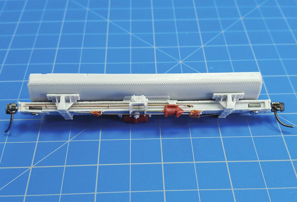
4 satisfied with the fit, attach the tank bottom to the center sill, ensuring that the bolster castings are equal distance from the edges of the tank bottom. Remember that the tank drain is towards to A end of the car. Drill and tap the bolsters for 2-56 truck screws going through the centersill and into the tank (Photos 7-11). h. Resin parts are supplied for the AB brake and a Tichy part for the K system. Install the one of your choice following the prototype photo for placement. From the photos it appears that the plumbing between the reservoir and the valve of the AB system went through the frame so there s no need to model this (unless you want to), as it can t be seen (Photos 7-11). i. Finish up tank bottom/centersill detailing by adding the clevis hangers, clevis and brake rods using the Tichy turnbuckles and wire. Note that there is no chain from the brake cylinder to the rod. The rod from the cylinder is connected to the chain, which extends down from the brake wheel. This connect will be done after the tank halves are assembled (Photos 7-11). 7
5


6 2. Tank top Before beginning the construction of the tank top, determine which manway cover and vents the car is to have. Over time these two items were replaced on many cars. a. If you choose to change the manway cover, remove the older screw on the cover on top of the dome and replace it with the new cover from the parts sheet. There are also new vents located on the parts sheet if you wish to construct a car with this feature. b. Drill for wire and form and install four grabs at the tank sides at the nut and bolt locations. Originally the cars did not have ladders from the running board up to the dome or a grab on the dome. These items seem to have been added when the cars were equipped with AB brakes, only being installed on the side with the brake cylinder. If you re installing a K brake system, remove the nut and bolt castings from the side of the dome. With AB brakes, install a grab here (Photos 13, 14). c. Dimples on the upper sides and ends of the tank are located at the handrail stanchions. Drill these out with a #76 drill. Precision Scale handrail stanchions are provided for the handrail (Photos 13-16). Drill out the castings with a #77 drill to 12 13

7 ensure that a.015 handrail wire will fit. (A note on prototype pipe sizes and model wire size: The handrails on these cars were constructed with 1 ¼ pipe. That s the inside diameter. In HO, a pipe of this size has an outside diameter of 0.019, slightly larger then what s provided in the kit. Wire of in size is available from such companies as Precision Scale. If you choose to use the larger size, care needs to be taken drilling out the stanchions so as not to bend them. Work progressing up in drill sizes, one number at a time, until the wire slips through.) Precision Scale provides in each set two castings with cylinders that are wider than the others. Place one of these on each side of the tank. One on opposite corners is suggested. Place the remaining stanchions on each side. Form the handrail by bending.015 wire using the jig provided or by eye while consulting the prototype drawings. Note that there is a notch in the handrail on the B end of the car to fit around the hand brake gear (Photos 14-16). There will be two pieces of handrail with each running down one side of the tank to the wide stanchions and including one curved end. Trim the ends of the pieces so that the ends of each meet within the wide stanchions. When satisfied, slide the two remaining stanchions around 14
. d.")

8 each end and attach them in the end of tank holes. Fix the wire ends inside the wide stanchion castings with glue. Soldering with a low wattage iron also works. Straighten the handrails as necessary by adjusting the angle of the stanchions (Photos 13-16). d. Drill out the holes for the running board supports along the bottom of the upper tank side with a #53 drill (Photo 17). Clean up the running board supports from the parts sheet and attach to the tank making sure each support is horizontal. A handy way to glue these is from the back side of the tank. When dry, trim the pins inside the tank, making sure that the upper tank fits on the lower tank. Consult the prototype plans as to the direction of the open portion of the supports, as they do change (Photos 12, 17)
. Attach the long running boards to each side of the tank between the end boards.")
9 e. Trim the running board ends to fit almost against the tank end and attach to the corner running board support, leaving about half of the end supports open for the side running boards. Notch the B end running board to clear the chain from the hand brake (Photos 12-16). Attach the long running boards to each side of the tank between the end boards. Make sure that there is a wide enough gap between the tank and running boards for the future installation of the tank bands. Notch the angles with the nut and bolt castings to fit around the running board supports and attach to the front corners of the running boards. The end of this angle is even with the second running board support from the end. Shape the end of the angle to match the running board end. Attach etched eyebolts under the nut and bolt locations on the angles and then install grabs into the eyebolts. Install the grabs on the running boards ends. Using the prototype plans as a guide make two coupler lift bars from wire and mount under the running board using the etched eyebolts. Attach the brass corner ladders to the underside of the running boards. These are centered between the corner running board supports. Carefully bend the ladder supports back at a 45 angle and attach to the running board supports on either side (Photos 12-15). 3. Complete the Detailing 17 We re now ready to join the tank halves. Before attaching the two tank sections together, remember that the tank drain goes towards the A end of the car. a. Attach the tank top to the tank bottom. b. You ll need to create the tank bands using the etched bar stock material and wire. There are two bands holding the tank at the bolsters at each end of the car. The bands are 16 long for the 6.5K car. Solder about 5 long pieces of the wire to the ends of the bands. Consult the prototype photos and drill #76 holes on each side of the bolster casting. Apply the bands over the tank between the handrails and running boards and into the holes drilled through the bolsters. Cement with ACC (Photos 18, 19). c. The dome ladder is only installed on the side of the car with the brake cylinder and only on cars equipped with AB brakes. For the ladder, drill two holes through the running board where the ladder is located. Fit the ladder between the handrail and running board with the ladder s legs going through the holes in the running board. Cement and when dry remove any protruding parts of the ladder from below the running board (Photos 13, 14, 18, 19). d. Carefully drill the brake wheel brackets with a #76 drill so that the brake wheel staff (0.015 wire) will slide through and remove the parts from the parts sheet. Drill the holes on the upper left section of the B tank end through and install the brake wheel brackets. The smaller bracket is nearer the

10 center of the car. Attach the brake wheel staff to one of the brass brake wheels and then slide it through the holes in the brackets. The brake wheel staff should not extend past the bracket nearest the center. Wrap chain once around the staff and touch with a drop of ACC. Let the other end slip through the notch in the walkway. Attach the chain roller guide to the centersill side under the brackets. Run the chain through the roller. Make an eyelet on the end of a piece of the wire and attach to the chain to create a rod and attach to the turnbuckle on the brake cylinder, leaving enough slack in the chain so that it hangs some (Photos 18, 19). e. Consulting the prototype photos, mount placards and route boards under the running boards in locations of your preference per the photos. Final mount the side vent on the dome if this is the option chosen. The model is now ready to paint. 18


11 4. Painting and Lettering Wash the model again with Dawn and allow it to thoroughly dry before painting. The entire model, including the trucks, is black. I like Scalecoat 1 No. 10 black as it provides a glossy surface for decals. Once decals are applied and all the air bubbles have been removed, spray with flat glaze. Two types of trucks from Tahoe Model Works are recommended for these cars: the Buckeye ARA 50-ton #TMW-006 and the ACF Arch Bar #TMW-003. Before attaching the trucks, remove the roller/pads on top of the truck bolster, as these interfere with the cast tank car bolsters. Finish with the amount of desired weathering. Create a waybill for the car and place it on the layout
UTLX Class X-3 10,000 Gallon Tank Car
 UTLX Class X-3 10,000 Gallon Tank Car UTLX Collection, courtesy of Steve Hile Introduction Thank you for your interest in Resin Car Works and this kit. Resin Car Works is not a business in the traditional
Kit 6.00 ACF Type 27, Class ,000 Gallon Insulated Tank Cars
 Kit 6.00 ACF Type 27, Class 103 10,000 Gallon Insulated Tank Cars Introduction Warranty Thank you for your interest in Resin Car Works and this kit. Resin Car Works is not a business in the traditional
Instructions: PS-2CD 4000 Model Kit Revised 7/2008
 Instructions: PS-2CD 4000 Model Kit Revised 7/2008 Plastic Parts included: Body shell Parts Sprue #1 Roof, trainline, gravity outlet gates, and centersill/endsill pieces Parts Sprue #2 Underframe bolster
PS 5077 cu. ft. Boxcar with EOC device. 1:29 scale resin craftsman kit. by Burl Rice
 PS 5077 cu. ft. Boxcar with EOC device 1:29 scale resin craftsman kit by Burl Rice www.burlrice.com Bill of materials (not included): Thick/medium viscosity CA PL adhesive, or Gorilla Glue Heavy Duty Construction
Kits SE #1.1 and SE #1.2 GATX Type 30 Class 103 8,000 Gallon Tank Car
 Kits SE #1.1 and SE #1.2 GATX Type 30 Class 103 8,000 Gallon Tank Car Introduction Thank you for your interest in Resin Car Works and this kit. Resin Car Works is not a business in the traditional sense.
40 & 50 Foot PS-1 Box Car Assembly Instructions
 40 & 50 Foot PS-1 Box Car Instructions Push the #2100 coupler/stirrup assembly onto the ends of the metal floor. Slide them into the slots and slightly lift the ends (wings), then press firmly on the front
Instructions: Bethlehem 70 ton Riveted Gondola Kit
 Instructions: Bethlehem 70 ton Riveted Gondola Kit Kit number 10900 01 Steel Floor or 10900 02 Wood Floor 8/2012 Parts included in this kit: 95004 01 Plastic Part Body Shell (either steel or wood floor
American Car and Foundry Type 27 ICC Class 103A & B 7000 and 8000 Gallon Acid Tank Cars
 American Car and Foundry Type 27 ICC Class 103A & B 7000 and 8000 Gallon Acid Tank Cars Introduction Thank you for your interest in Resin Car Works and this kit. Resin Car Works is not a business in the
Instructions: GSC 60 Flatcar Kit with or without bulkheads Tangent Part Number: and /2016
 Instructions: GSC 60 Flatcar Kit with or without bulkheads Tangent Part Number: 11000-01 and 11000-02 5/2016 Thank you for purchasing the Tangent Scale Models GSC 60 Flatcar Kit! A few quick notes before
28 ft. Ventilated (Combination) Box Car
 Box Car") 28 ft. Ventilated (Combination) Box Car Introduction This laser cut wood kit is an HO scale model of a 28 ft. Ventilated (also known as a Combination) Box Car. The model is based on the Illinois Central
28 ft. Ventilated (Combination) Box Car Introduction This laser cut wood kit is an HO scale model of a 28 ft. Ventilated (also known as a Combination) Box Car. The model is based on the Illinois Central
HOn3-118 Denver, Boulder & Western Box Car
 HOn3-118 Denver, Boulder & Western Box Car 30 32 35 29 28 34 Door and Track on End Opposite Brake Wheel ONLY 31 3 36 2 6 24 33 Deadwoods Center Line of Coupler 27 We would like to thank you for purchasing
CONCEPT MODELS INSTRUCTIONS FOR PRODUCT 60,000 GALLON TANK CAR El Toro Way Stockton, CA 95210
 CONCEPT MODELS Web Address: http://www.con-sys.com Email: concept_models@con-sys.com 8810 El Toro Way Stockton, CA 95210 INSTRUCTIONS FOR PRODUCT 60,000 GALLON TANK CAR 2 CONCEPT MODELS PARTS GATX/UTLX
DIY MODELS THRALL 5-UNIT ARTICULATED WELL CAR W. Canyon Creek Dr. Maricopa, AZ
 THRALL 5-UNIT ARTICULATED WELL CAR DIY MODELS 44609 W. Canyon Creek Dr. Maricopa, AZ 85139-5019 DIMENSIONS Length End Units 56 2-5/16 Width (Inside Well at Bottom) 8-1 3/4 Length, Inter. Units 50 13-3/4
Peter Krause ABN
 Peter Krause ABN 25 736 637 163 T/as O-Aust Kits PO Box 743 ALBANY CREEK QLD 4035 AUSTRALIA Phone +61 (0)7 3298 6283 (7.00pm to 9.30pm ONLY) Facsimile +61 (0)7 3298 6287 (24 hours) Mobile 0419 680 584
FINNEY7 4500G May17 SR 4500G TENDER. Fig 1. Original Appearance. Side raves Sanding gear Front water fillers TIA Water treatment system
 Fig 1. Original Appearance Side raves Sanding gear Front water fillers TIA Water treatment system 4500G - 3 Fig 2. Rebuilt Condition Cut down side raves with fire iron tunnels# TIA removed and replaced
CONCEPT MODELS UTLX 80006,80020 CRYOGENIC TANK CAR KIT INSTRUCTIONS Sheep Ranch Rd. Mountain Ranch, CA 95246
 CONCEPT MODELS Web Address: http://www.con-sys.com Email: concept_models@con-sys.com 8331 Sheep Ranch Rd. Mountain Ranch, CA 95246 UTLX 80006,80020 CRYOGENIC TANK CAR KIT INSTRUCTIONS 2 CONCEPT MODELS
Precision Steel Car s 100 T Steel Coil Car
 Precision Steel Car s 100 T Steel Coil Car Precision Steel Car www.precisionsteelcar.com info@precisionsteelcar.com Paul Vernon: (513) 571-5739 Revised 4/30/2009 Contents of Kit Main Tube Side Frame 2
CONCEPT MODELS INSTRUCTIONS FOR THE KASGRO KRL SPECIAL DEPRESSED CENTER FLAT CARS El Toro Way Stockton, CA 95210
 CONCEPT MODELS Web Address: http://www.con-sys.com Email: concept_models@con-sys.com 8810 El Toro Way Stockton, CA 95210 INSTRUCTIONS FOR THE KASGRO KRL 204000-2 SPECIAL DEPRESSED CENTER FLAT CARS 2 CONCEPT
Scratch Build a Water Tower
 Here s some Prototype details Photos Courtesy of Rodney Doster Water Spout and Discharge Pipe Tank Bands Here s some more Prototype details Photos Courtesy of Rodney Doster Weather Vane as a Finial Using
VICTORIAN RAILWAYS QR BOGIE OPEN WAGON
 C/- P.O. Rhyll, Victoria, 3923. VICTORIAN RAILWAYS QR BOGIE OPEN WAGON Prototype Notes QR number 1 was built at the VR Newport workshops in 1889, being the forerunner of a long lived and useful class of
CONCEPT MODELS SP DOUBLE STACK CONTAINER CARS INSTRUCTIONS Sheep Ranch Rd. Mountain Ranch, CA Web Address:
 CONCEPT MODELS Web Address: http://www.con-sys.com 8331 Sheep Ranch Rd. Mountain Ranch, CA 95246 SP DOUBLE STACK CONTAINER CARS INSTRUCTIONS 2 CONCEPT MODELS PARTS Item No. PART NO. DESCRIPTION QTY. 1
VICTORIAN RAILWAYS GY WAGON
 C/- P.O. Rhyll, Victoria, 3923. VICTORIAN RAILWAYS GY WAGON Prototype Notes The GY wagon fleet was one of the largest single classes of goods vehicle in VR service and was primarily a bulk commodities
NSWGR Class SRC Refrigerated Wagon Kitset in 7mm Scale
 O-Aust Kits PO Box 743 ALBANY CREEK QLD 4035 AUSTRALIA Phone +61 (0)7 3298 6283 (7.00pm to 9.30pm ONLY) Facsimile +61 (0)7 3298 6287 (24 hours) Mobile 0419 680 584 Email pa_rl_krause@bigpond.com Web www.oaustkits.com.au
CA to each one. You may have to hold the end down while to glue sets or use an accelerator like I did.
 The following information and photographs are what I did to build the kit. Your methods and needs may differ from this which is fine. There is no right or wrong way if you are used to scratch building.
Southern Pacific C-30-4/6 Bay Window Caboose N-Scale & HO-Scale
 Southern Pacific C-30-4/6 Bay Window Caboose N-Scale & HO-Scale Before Starting PREPARING BRASS The easiest way to remove the brass parts from the sheet they are produced on, is to use rail nippers. The
FINNEY7 SR 5500G TENDER IN ORIGINAL CONDITION
 IN ORIGINAL CONDITION Fig 1. Original Appearance Side raves Sanding gear TIA Water treatment system 5500G - 3 5500G TENDER IN REBUILT CONDITION Fig 2. Rebuilt Condition Cut down side raves with fire iron
the wire, less is better. And make sure the bends on each truss wire are in line with the other. See the next photo.
 The following information and photographs are what I did to build the kit. Your methods and needs may differ from this which is fine. There is no right or wrong way if you are used to scratch building.
Trim down the piece of casting being pointed to with the tip of the pencil in the first picture. It is only the 'inboard casting that needs to be
 1. File off the moulding pips from the wheel flanges. File the ends of the tube smooth and de-burr. Assemble the wheel sets with a drop of car engine oil on the axles. Glue the wheel sets into place. 2.
O-Aust Kits. QR Class CLF Louvred Wagon Kitset in O Scale 1:48
 O-Aust Kits PO Box 743 ALBANY CREEK QLD 4035 AUSTRALIA Phone +61 (0)7 3298 6283 (7.00pm to 9.30pm ONLY) Facsimile +61 (0)7 3298 6287 (24 hours) Mobile 0419 680 584 Email pa_rl_krause@bigpond.com Web www.oaustkits.com.au
After the glue dries, trim the trussrod ends with your cutting pliers
 The following information and photographs are what I did to build the kit. Your methods and needs may differ from this which is fine. There is no right or wrong way if you are used to scratch building.
Shay Tender Frame Fabrication
 Shay Tender Frame Fabrication Nelson Riedel Nelson@NelsonsLocomotive.com Initial:3/15/03 Last Revised: 06/05/2004 This page shows additional detail on the tender frame members and some of the processes
FUSELAGE CONSTRUCTION
 FUSELAGE CONSTRUCTION Note: prior to building and gluing on the work surface use protective covering on your building surface. (wax paper or clear wrap) Fit the laser cut Fuselage Front and Fuselage Rear
After the glue dries, trim the trussrod ends with your cutting pliers.
 The following information and photographs are what I did to build the kit. Your methods and needs may differ from this which is fine. There is no right or wrong way if you are used to scratch building.
Continue gluing the remaining top parts ensuring the angled piece is glued well. Set aside and let dry. See photo below
 Radiator rev 1.1 The SE5a s radiator is one of the most recognized radiators in WW1. It is one of the components that defines the SE5a. The original SE5a has seen multiple radiator designs used during
Scratchbuild A Backwoods Water Tank Part V - Making the Frost Box and Hanging the Water Spout
 Scratchbuild A Backwoods Water Tank Part V - Making the Frost Box and Hanging the Water Spout By Dwight Ennis In this section, we're going to make the Frost Box, and we'll build the Spout Hanger Assembly
Additional Parts List:
 THE TIME MACHINE Additional Parts List: In addition to the cast resin parts enclosed in this kit, there should also be a plastic bag containing the following items needed to complete your time machine
SCHWERE PLATTFORMWAGON TYPE SSY 60TON
 TWS 5094 SCHWERE PLATTFORMWAGON TYPE SSY 60TON Congratulations on purchasing one of the finer aftermarket resin kits sets available. The photo below is of the completed kit. The Panther tank is not included
Billy Body Kit HBK5 CHECKLIST. Modular Locomotive System Instruction Manual for HBK5 Billy Body Kit. Checked
 Billy Body Kit HBK5 CHECKLIST 1 Cab body panel (folded). 1 Cab floor. 1 Cab front panel. 1 Roof. 1 Body tank support. 2 Boiler bands with M2 Long Steel Screws & Nuts fitted. 1 Brass dome. 1 Cast brass
MIDLAND RAILWAY JOHNSON 6-WHEEL 3,250g TENDER
 MIDLAND RAILWAY JOHNSON 6-WHEEL 3,250g TENDER These tenders were built in large numbers together with others of varying water capacity. During their life some were fitted with water pickup apparatus and
Tool Wagon Assembly Instructions
 Tool Wagon Assembly Instructions Adhesives Wood to wood joints are best done with a PVA wood glue but a good quality, slow acting (beware of instant grab ) cyanoacrylate super glue can be used if preferred.
Modular Locomotive System Instruction Manual for HBK22 Fowler Body Kit
 Modular Locomotive System Instruction Manual for HBK22 Fowler Body Kit Roundhouse Engineering Co. Ltd. Units 6-10 Churchill Business Park. Churchill Road, Wheatley. Doncaster. DN1 2TF. England. Tel. 01302
N Scale Concrete Coal Dock Instruction Manual
 N Scale Concrete Coal Dock Instruction Manual 1. General Overview This kit combines precision laser cut acrylic, photo etched brass and wood parts to make a highly detailed model of the Roberts and Schaefer
SE5a Instrument Board part 2 - rev 1.1
 SE5a Instrument Board part 2 - rev 1.1 Fuel (Petrol) Valve This valve uses two circular name plates, eight brass screws, one black plastic base, copper wire and two black plastic risers. You can pick any
C/- P.O. Rhyll, Victoria, 3923.
 C/- P.O. Rhyll, Victoria, 3923. FREIGHT AUSTRALIA VHGF BULK GRAIN HOPPER WAGON Prototype Notes: Tulloch Limited of Rhodes, N.S.W., constructed an initial batch of one hundred aluminium wheat hopper wagons
Brassmasters
 Brassmasters www.brassmasters.co.uk Scale Models LONDON & NORTH EASTERN RAILWAY 4200 GALLON GROUP STANDARD TENDER KIT Designed by Martin Finney 4MM SCALE OO - EM - P4 INSTRUCTIONS AND PROTOTYPE NOTES PO
You can print these instructions by downloading the PDF here: Boxcar Assembly PDF
 The following information and photographs are what I did to build the kit. Your methods and needs may differ from this which is fine. There is no right or wrong way if you are used to scratch building.
Note - the nose ribs and are thinner than the main ribs. These nose ribs will use a thinner rib cap than the ribs. This is per design.
 Stabilizer rev 1.2 The SE5a stabilizer is the heartbeat of the tail and is recreated like the full scale version. All tail pieces depend on the stabilizer. It uses the steel fittings, pulleys, inspection
*Patent Pending. *Trademarked. Series II. Glass Conversion Kit. (888) One-Products (888)
 One-Products (888)") *Patent Pending *Trademarked Series II Glass Conversion Kit www.onepieceproducts.com (888) One-Products (888) 663-7763 Installation Manual Full One Piece Door Glass Conversion Kit Series II 1967-1972 Chevy
*Patent Pending *Trademarked Series II Glass Conversion Kit www.onepieceproducts.com (888) One-Products (888) 663-7763 Installation Manual Full One Piece Door Glass Conversion Kit Series II 1967-1972 Chevy
-1- Coach Instructions.
 -1- Coach Instructions. Insert the bogie pivot pins through the bottom of the coach body ensuring the dimples fit into the recesses. Glue the.06 x.25 short strips each side of the pivot head, bridge the
Southern Ry Wood Rack (1951 rebuild - Roman) (HO)
 (HO)") Page1 Wright Trak Models, LLC. P O Box 158 Clarkesville, GA 30523 Web: http://wrighttrak.com/ Fax: (888) 841-7092 Southern Ry. 40 6 Wood Rack (1951 rebuild - Roman) (HO) NOTE This HO kit was designed by
Page1 Wright Trak Models, LLC. P O Box 158 Clarkesville, GA 30523 Web: http://wrighttrak.com/ Fax: (888) 841-7092 Southern Ry. 40 6 Wood Rack (1951 rebuild - Roman) (HO) NOTE This HO kit was designed by
20 ORE CAR INSTRUCTIONS. Kit )rv \M TAURUS PRODUCTS P.0. BOX 6534 ORANGECA m WeWWW. Dronerty efi N456 Inc.
rv \M TAURUS PRODUCTS P.0. BOX 6534 ORANGECA m WeWWW. Dronerty efi N456 Inc.") 20 ORE CAR Kit 3305 - INSTRUCTIONS TAURUS PRODUCTS )rv \M P.0. BOX 6534 ORANGECA. 92667 m WeWWW Dronerty efi N456 Inc. Thank you for selecting this TAURUS PRODUCTS kit. We sincerely hope that you will
20 ORE CAR Kit 3305 - INSTRUCTIONS TAURUS PRODUCTS )rv \M P.0. BOX 6534 ORANGECA. 92667 m WeWWW Dronerty efi N456 Inc. Thank you for selecting this TAURUS PRODUCTS kit. We sincerely hope that you will
Tools and Tips: ( 1 )
") Tools and Tips: As you build instructions will show in my many picture manual how to assemble. You can use your own methods as you desire, my results are very good. A smooth, flat work surface is very
Tools and Tips: As you build instructions will show in my many picture manual how to assemble. You can use your own methods as you desire, my results are very good. A smooth, flat work surface is very
Obtained from Omarshauntedtrail.com
 DaveintheGrave's Halloween Props Animated Crawling Skeleton Build a life-size skeleton torso that realistically crawls across the lawn one arm at a time. 1. Motor Base and Linkage Assembly BASE - I used
Tools and Tips: ( 1 )
") Tools and Tips: As you build instructions will show in my many picture manual how to assemble. You can use your own methods as you desire, my results are very good. A smooth, flat work surface is very
Tools and Tips: As you build instructions will show in my many picture manual how to assemble. You can use your own methods as you desire, my results are very good. A smooth, flat work surface is very
G. Building the Cab, Cab Roof and Cab Boiler Extension Page 14 and Backhead.
 G. Building the Cab, Cab Roof and Cab Boiler Extension Page 14 and Backhead. Cab. In order to ensure that the cab and tender would actually look right, as what often appears on a drawing is not always
Building Instructions Diva cabin boat
 Building Instructions Diva cabin boat Order no. 3093/00 aero-naut Modellbau Stuttgarterstr. 18-22 D-72766 Reutlingen / Germany http://www.aero-naut.com 1 For pictured building instructions please see the
N. 15th Street, Middlesboro, KY FLIP TARP DUMP BODY INSTALLATION INSTRUCTIONS
 1-800-248-7717 1002 N. 15th Street, Middlesboro, KY 40965 FLIP TARP DUMP BODY INSTALLATION INSTRUCTIONS Congratulations on your purchase of a Mountain Flip Tarp Dump Body tarping system. With tarping systems
Assembly Instructions 10 X 10 Aluminum Roof Support
 Assembly Instructions 10 X 10 Aluminum Roof Support Aluminum Roof Support Bolt Package 16-5/16 X 2 ¼ SS Bolt 24-5/16 X 1 SS Bolt 40-5/16 SS Nylon Lock Nuts 16-5/16 SS Flat Washers 28-4 ½ Wood Screws 36-1
Adding Buffers to the SEM Z van
 Adding Buffers to the SEM Z van Throughout the 1930s, 40s and early 50s the Victorian Railways carried out a program of conversion of rolling stock to auto couplers, with a particular emphasis on goods
Precision Steel Car s 40 Ft. Stock Car
 Precision Steel Car s 40 Ft. Stock Car Precision Steel Car Website: www.precisionsteelcar.com E-mail: info@precisionsteelcar.com Revised 12/3/2018 Paul Vernon: (513) 571-5739 PSC 40 ft. Stock Car Kit:
Build the Spitfire: Step-By-step. Pack 7 Stages 61-71
 Pack 7 Stages 61-71 1 Stage Contents Page Number 61 212-215 62 216-218 63 219-221 64 222-224 65 225-228 66 229-231 67 232-235 68 236-238 69 239-241 70 242-245 71 246-249 Editorial and design by Continuo
SM21D SJA conversion for Bachmann MEA wagon.
 The preparation of the etch is straightforward. Bends can be made using ordinary pliers and hand pressure. They do not require the use of bending jigs such as hold and fold. 90 0 folds have the half etch
Reversing Gear. Shay Reversing Gear
 Shay Nelson Riedel Nelson@NelsonsLocomotive.com Initial: 9/23/03 Last Revised: 06/05/2004 The reversing gear is another one of those pieces I've been putting off. The reason for the postponement was that
woodworkersjournal.com MATERIAL LIST
 MATERIAL LIST T x W x L 1 Legs (2) 1 1 2" x 3 1 2" x 36 7 16" 2 End Uprights (2) 1 1 2" x 3 1 2" x 32 1 2" 3 Stringers (4) 1 1 2" x 3 1 2" x 42" 4 Top Cladding, Long (2) 3/4" x 7 1 4" x 65 3 4" 5 Side
Cobra X Q Construction Tips Construction: Bel y pan
 Cobra X Q Construction Tips : The white plastic in this kit is high impact styrene. It can be painted with most types of coatings if light coats are applied this is necessary due to the thickness of the
Nanton Grain Mill Assembly
 ( 1 ) Nanton Grain Mill Assembly Locate package for assembling storage building. These are cut from 1/8 masonite. Inspect and lightly sand edges where it will be bonded. Use white glue or CA glue to bond.
Bates 1/8 scale B-26. Parts List. Instructions
 Bates 1/8 scale B-26 Vacuform Pieces Swivel Ball 1 Cockpit Floor 1 Ball 2 Cockpit Back Wall 2 Two Flanges 3 Dash 3 Seven 0-64 x 1/4 Bolts 4 Dash Hood 4 Seven 0-64 Nuts 5 Center Console 6 Pilot Seat Fire
Assembly Instructions 10 X 10 Aluminum Frame Building
 Assembly Instructions 10 X 10 Aluminum Frame Building 27 97 9 8 47 36 74 52 10 10 X 10 Square Building W/ Dome Includes: The Steel Entry Door with a Dead Bolt Lock assembly and Aluminum Door Frame. Metal
CONCEPT MODELS INSTRUCTIONS FOR UP DC-10 WING CAR El Toro Way Stockton, CA Web Address:
 CONCEPT MODELS Web Address: http://www.con-sys.com 8810 El Toro Way Stockton, CA 95210 INSTRUCTIONS FOR UP DC-10 WING CAR 2 CONCEPT MODELS PARTS DC-10 WING CAR Item No. Part No. DESCRIPTION QTY. 1 2003-1
VICTORIAN RAILWAYS QB WELL WAGON
 C/- P.O. Rhyll, Victoria, 3923. VICTORIAN RAILWAYS QB WELL WAGON Prototype Notes QB1 was constructed at the VR Newport workshops in 1902. That was the sole representative of the class until a construction
BRF-022 YGH SEALION. Building Instructions
 Tel 07747 018544 www.prmrp.com BRF-022 YGH SEALION Building Instructions SCALE MODEL PRODUCT FOR ADULT MODELLERS ONLY. WHITE METAL CONTAINS LEAD WASH HANDS AFTER USE. MAY CONTAIN SMALL PARTS. ETCHED BRASS
LocoGear. Technical Bulletin - 14 November 28, 2003 Copyright 2003 by LocoGear LIVE STEAM CASTINGS. Tech Bulletin - 14
 LIVE STEAM CASTINGS LocoGear Tech Bulletin - 14 John D.L. Johnson 3879 Woods Walk Blvd Lake Worth, FL 33467-2359 jjohnson@locogear.com www.locogear.com Technical Bulletin - 14 November 28, 2003 Copyright
This is a modified, 1:22.5 scale, SR&RL
 Build a :22.5-scale SR&RL caboose by Ted Stinson Wiscasset, Maine Plan set #95A This is a modified, :22.5 scale, SR&RL caboose. It closely follows the lines of the Nº 556 SR&RL caboose. However, the model
This is a generic, 1:20.3-scale Climax.
 :20.3-scale Climax by Ted Stinson Wiscasset, Maine Plan set #82 This is a generic, :20.3-scale Climax. The class-a Climax was the first widely used logging locomotive. It was designed to give maximum tractive
Scratch-build a 1:20.3 scale 29-6 Flatcar
 Scratch-build a 1:20.3 scale 29-6 Flatcar Chapter 1 Building the frame and decking By Wayne Spence Brisbane, Australia Please take the time to refer to the following link, in which Dwight Ennis describes
ADJUST-A-VIEW HALF CIRCLE INSTALLATION INSTRUCTIONS
 Omega Mfg. Corporation Two Rivers, WI (800) 874-9594 www.adjustaview.com Proudly Serving Customers Since 1976 Page 1 of 7 MATERIAL LIST ADJUST-A-VIEW User Instructions ADJUST-A-VIEW Installation Instructions
10' Building Instructions for kit CC25 Caledonian Railway 20 Ton Brake Van
 Jim Smellie Mar. 1995 10' Building Instructions for kit CC25 Caledonian Railway 20 Ton Brake Van 20 TONS 3 5360 0 Caley Coaches Ltd CC25 Building Instructions Section 1 Prototype Notes A batch of 40 of
START HERE BEFORE YOU BEGIN FIG 1 STEP 2
 PROFESSIONAL INSTALL RECOMMENDED REAR MODULAR / MULTI LED ROOF MOUNTS PART#: Z350040 / Z350050 REAR ROOF LED LIGHT MOUNTS Parts included (1) - Driver Side Roof Mount Upright (1) - Passenger Side Roof Mount
High performance 90mm fiberglass jet
 High performance 90mm fiberglass jet Assembly manual For intermediate and advanced fliers only! Specs Wingspan: 1255mm Fuselage length: 1250mm Flying weight: 2600-3000g Wing area: 22.6 dm² Wing loading:
BRF-020 Type YCV Turbot Spoil Wagon. Building Instructions
 Tel 07747 018544 www.prmrp.com BRF-020 Type YCV Turbot Spoil Wagon Building Instructions SCALE MODEL PRODUCT FOR ADULT MODELLERS ONLY. WHITE METAL CONTAINS LEAD WASH HANDS AFTER USE. MAY CONTAIN SMALL
ADJUST-A-VIEW QUARTER CIRCLE INSTALLATION INSTRUCTIONS
 Omega Mfg. Corporation Two Rivers, WI (800) 874-9594 www.adjustaview.com Proudly Serving Customers Since 1976 Page 1 of 5 MATERIAL LIST ADJUST-A-VIEW User Instructions ADJUST-A-VIEW Installation Instructions
Shay Cab - Floor & Roof
 Shay Cab - Floor & Roof Nelson Riedel Nelson@NelsonsLocomotive.com Initial: 1/20/04 Last Revised: 06/06/2004 Cab Floor: A cab floor was made at the same time as the tender floor. I was unhappy with some
EXTREME LOAD no. TWO
 1602 - EXTREME LOAD no. TWO Kit Features: 22' 4 " x 14' x 3'-6 Oversize Load 49mm (1.9") actual height Bolt Head Details Welded Load Mounting Fins Painting Handles Tools Required: Hobby Knife Tweezers
Ford Ranger / Bronco II Set Part # Rev B 5-04
 Ford Ranger / Bronco II Set Part # 21008 Rev B 5-04 Step 1: Prior to Installation: A) Fit: Verify the fit of the flares to vehicle. (Some filing, sanding, or cutting may be necessary to ensure proper fit).
7mm/0Gauge BRF 025 ZUV SHARK Plough Brake. Building Instructions
 Tel 07807 225801 www.prmrp.com 7mm/0Gauge BRF 025 ZUV SHARK Plough Brake Building Instructions SCALE MODEL PRODUCT FOR ADULT MODELLERS ONLY. WHITE METAL CONTAINS LEAD WASH HANDS AFTER USE. MAY CONTAIN
Citabria Pro. Aerobatic Parkflyer. by Joel Dirnberger
 Citabria Pro Aerobatic Parkflyer by Joel Dirnberger Revision C: December 21, 2004 Citabria Pro Building Instructions Length: Wingspan: Wing Area: Flying Weight: Wing Loading: Functions: Specifications:
One Piece Products. Series III El Camino ( ) One Piece Door Glass Conversion Manual.
 One Piece Door Glass Conversion Manual.") One Piece Products Series III El Camino (1964-1967) One Piece Door Glass Conversion Manual *Registered Trademark www.onepieceproducts.com (888)One Products (888)663-7763 1 Installation Instructions_ 1964-1967
One Piece Products Series III El Camino (1964-1967) One Piece Door Glass Conversion Manual *Registered Trademark www.onepieceproducts.com (888)One Products (888)663-7763 1 Installation Instructions_ 1964-1967
INSTALLATION INSTRUCTIONS
 www.marwincompany.com Kit Number Door Height Rough Opening Height KD200BB68 80 84 ½ KD200BB70 84 88 ½ KD200BB80 96 100 ½ INSTALLATION INSTRUCTIONS 200BB SERIES KD POCKET DOOR FRAME FOR 2 X 4 STUD WALLS
FLIP TARP SINGLE & DOUBLE UNDERBODY TRAILERS
 1-800-248-7717 1002 N. 15th Street, Middlesboro, KY 40965 FLIP TARP SINGLE & DOUBLE UNDERBODY TRAILERS INSTALLATION INSTRUCTIONS Congratulations on your purchase of a Mountain Flip Tarp Trailer system.
Instructions for Lighting an S Scale Caboose
 Instructions for Lighting an S Scale Caboose The S Scale Caboose lighting kit is adaptable for most caboose models of rolling stock including American Flyer (TM) and contains the same components as found
Oxford Stalls Installation Instructions
 Oxford Stalls Installation Instructions RAMM Horse Fencing and Stalls 13150 Airport Hwy. Swanton, OH 43558-9615 1-800-434-8456 Rev. 8/15/17 Before You Start Typical stall sizes are 10 x 10, 12 x 12 or
Ziroli D-17 Beech Staggerwing
 Ziroli D-17 Beech Staggerwing Parts List Vacuform Parts: Miscellanous Pieces 1 Four Side Panels 1 3/16" Tube, 2" Long 2 Lower Dash - Back Dash 2 Felt, 12x24 3 Dash 3 Cordury 12x24 4 Dash Hood 4 Aluminum
GWR Macaw B Bogie Bolster. Building a Diagram J4 with moveable bolster pins, complete with all chains from a Conniosseur kit.
 GWR Macaw B Bogie Bolster. Building a Diagram J4 with moveable bolster pins, complete with all chains from a Conniosseur kit. Jim M c Geown s kit for the Macaw, designed to build a vehicle that covers
Taco Bell Restaurant kit in HO scale
 Taco Bell Restaurant kit in HO scale Parking lot base and cars not included This kit includes all building parts milled in white styrene plastic, clear window glazing, Plastruct tile roofing, and logo
Dura-Lock Roof System
 DLR-14 Dura-Lock Roof System Assembly and Installation Instructions Read the instructions before starting the job. They explain the steps required to produce a finished product that will meet factory specifications.
TF Model Jet Ranger 700
 TF Model Jet Ranger 700 Assembly Instructions for Jet ranger 700 For Trex 600 E mechanic Thank you for purchasing TF Model's 700 Jet Ranger. Please read through this assembly manual carefully before proceeding
Slide the stock rubber tank mount caps onto the ends of the CS-1 tank mount:
 RYCA CS-1 BODY PARTS INSTALLATION GUIDE [The CS-1 installation guides should be used as supplements to the videos found on our Youtube Channel. There is no strict order to the build process, but it is
INSTALLATION INSTRUCTIONS. Deluxe Continuous Hinge Inline Door & Panel Shower Enclosure QCI5230
 INSTALLATION INSTRUCTIONS Deluxe Continuous Hinge Inline Door & Panel Shower Enclosure QCI5230 QCI5230 Rev 0 6 shower new QCI5230 Rev 0 Page 2 Certified 06/20/2016 Parts List A. Curb (w/ weep holes) (1)
AIR MASTER SYSTEMS INSTALLATION GUIDE TABLE OF CONTENTS
 AIR MASTER SYSTEMS INSTALLATION GUIDE TABLE OF CONTENTS GENERAL INFORMATION...1 Freight Damage... 1 Repairing Paint Scratches...1 BASE CABINETS... 2 Drawer Removal and Reinstallation...2 Replacing Drawer
Chapter 1. Beam and Sill Plates
 Chapter 1. Beam and Sill Plates 1.1 ESTABLISHING SQUARE SILL PLATE CHALK LINES 1.2 INSTALLING TREATED SILL PLATES 1.3 INSTALLING LAMINATE BEAM Tools needed by volunteers: Hammer Nail apron Tape measure