63601 PARTS LIST ILLUS NO. PART NO. DESCRIPTION QTY.
|
|
|
- Benedict Mathews
- 5 years ago
- Views:
Transcription
1 63601 PARTS LIST DRAWING NO. 1 1 W-A Right Cover 1 M-O Right Hand Insulation 1 2 W-A Left Cover 1 M-O Left Hand Insulation 1 3 M-S XLO50 Belt 1 4 M-S Motor Pulley 1 5 M-S V Belt 1 6 M-O Plexiglass Cover 1 AA M-S X 1 Soc. Head Cap Screw 6 I
2 DRAWING NO. 2 7 M-S Stacker Switch 1 8 M-S Control Knob 1 9 M-S On Switch 1 10 W-O Switch Guard 1 11 M-S Length Adjust Switch 1 12 M-S Stop Switch 1 13 Comes With # MRS Potentiometer 1 15 M-S V Relay Socket 1 M-S Tab Connector 2 16 M-S V Relay 1 17 M-S V Control 1 18 M-S Top Decal 1 19 M-S Calibration Scale 1 20 W-O Right Hand Rail 1 Illus. No W-O Left Hand Rail 1 22 W-A Drive Motor Assembly 1 23 M-S Micro Switch 2 24 W-O Insulator 1 25 M-S Socket 1 26 M-S Rubber Feet With Stud 4 Illus. No. HH 27 M-S Safety Cover Micro Switch 3 28 W-A Micro Switch Bracket 3 29 MRS Motor Brush Replacement 2 30 M-O Cover Tension Strip 1 31 M-S Fuse Holder 1 32 M-S Amp Fuse 1 33 M-S Strain Relief Bushing 1 33A M-O V Power Cord 1 AA M-S X 3/8 Flat Head Screw 8 BB M-S X 3/8 Soc. Head Cap Screw 21 CC M-S # 10 Flat Washer 33 DD M-S # 10 Lock Washer 30 EE M-S Sems Nut 10 FF M-S X 3/8 Soc. Head Cap Screw 9 GG M-S # 8 Flat Washer 10 HH M-S ¼-20 Kep Nut 8 II JJ M-S # 6 Flat Washer 16 II
3 III
4 DRAWING NO M-S LO50 3/8 Hole Lwr. Slit. Sft. Pulley 1 M-S ¼-20 X 3/8 Set Screw 2 35 M-S XLO37 Belt 1 36 M-S Thumb Screw 2 37 W-O Paper Control Side Guide 2 38 W-O Paper Control 2 M-S Set Screw 2 39 M-S XLO37 Pulley 1 M-S X ¼ Set Screw 1 40 M-O Fixed Rod 1 41 M-O Tape Control Rod 2 42 M-S Tape Clamp W-O Tape With Hole M-O Friction Rod 1 45 W-A Right Hand Slitter Assembly 1 46 W-A Left Hand Slitter Assembly 1 47 M-O Slitter Knob 2 48 W-O Nut 2 49 M-O Blade 4 50 M-S Wave Washer 1 51 W-O Upper Slitter Shaft 1 52 W-O Lower Slitter Shaft 1 53 M-O Idler Rod 1 53A M-S Rubber Wheel 3 53B M-S Infeed Spacer 2 54 M-S Spacer 1 55 M-S Gear 1 M-S ¼-20 X 3/8 Set Screw 1 56 M-O Infeed Roller 1 M-S End Cap 2 M-O Infeed Roll Rod 1 M-S Roll Pin, 1/8 X W-O Paper Support 2 58 W-A Locking Rail 1 59 M-S ¼ Snap Ring 6 60 M-S Wave Washer 2 61 Self Aligning Bushing 6 62 M-O Idler Rod 2 63 M-S Upper Slitter Shaft Gear 1 64 M-S Hand Knob 1 M-S ¼ -20 X 3/8 Set Screw 1 65 W-A Gear Safety Assembly 1 IV
5 DRAWING NO. 3 65A M-O Shaft Only 1 M-S Roll Pin 1/8 X 15/ B M-S Spring 1 66 Grip Ring 4 67 W-O Deflector 1 68 M-S XLO37 Pulley 1 M-S X ¼ Set Screw 1 NOT SHOWN WRO Box End Slitter Blade Adjustment Wrench WRA Slitter Shaft Wrench AA M-S # 4 X ¼ Pan Head Screw 2 BB M-S X 1 Socket Head Cap Screw 2 CC M-S ¼ Flat Washer 9 DD M-S ¼-20 X 3/8 Set Screw 8 FF M0S X ¼ Set Screw 6 HH M-S ¼-20 Flex Lock Nut 1 II M-S Kep Nut 24 DRAWING NO M-S Retaining Ring 2 70 W-O Right Hand Arm 1 M-S ¼-20 X 3/8 Set Screw 1 71 W-A Left Hand Arm & Stud Assembly 1 72 W-O Eccentric 2 M-S Bushing 4 73 M-S Idler Double 1 M-S Bushing 1 M-S Retaining Ring 3 74 M-S Pulley Roller 2 75 M-S XLO37 Belt 2 AA M-S ¼-20 X 3/8 Set Screw 6 V
6 VI
7 DRAWING NO W-O Cover Tape Guide 1 77 M-S Indicator Point 1 78 M-S Bearing 8 79 M-S Bearing Pad 4 80 M-O Top Feed & Snap Roller 2 81 W-O Tear Bar 1 W-O Lower Paper Control 1 M-S Kep Nut 3 M-S X 3/8 Soc. Head Cap Screw 3 82 M-O ½ Spacer 6 83 M-O /8 Spacer M-S Small Gear 3 85 M-O Feed Roll Bearing Block 2 86 M-S Calibration Scale 2 87 W-O Rack 1 88 M-S Retaining Ring 3 89 M-O Pinion Gear 2 M-S X ¼ Set Screw 1 90 M-S Bushing 2 91 M-O Pinion Shaft 1 VII
8 DRAWING NO W-A Motor & Worm Assembly 1 M-S Connector 2 M-S Connector 1 93 M-S Worm Gear 1 94 W-O Motor Support 1 M-S X ¼ Set Screw 1 95 Clamp 1 96 M-S Capacitor Mounting Bracket 1 97 M-S V Capacitor 1 98 M-O Bottom Feed Roller 1 AA M-S X 3/8 Soc. Head Cap Screw 8 BB M-S ¼ Internal Tooth Lock Washer 9 CC M-S ¼ Flat Washer 9 DD M-S X 3/8 Soc. Head Cap Screw 21 EE M-S # 10 Internal Tooth Lock Washer 30 FF M-S X ½ Soc. Head Cap Screw 5 HH M-S X ½ Button Head Cap Screw 2 JJ M-S X ¼ Set Screw 6 KK M-S Kep Nut 24 LL M-S X 1 ¼ Set Screw 2 MM M-S X 3/16 Round Head Screw 1 VIII
9 DRAWING NO See Drawing Number 3 78 See Drawing Number 5 79 See Drawing Number 5 80 See Drawing Number 5 82 See Drawing Number 5 83 See Drawing Number 5 84 See Drawing Number 5 99 See Drawing Number 5 For Breakdown 100 W-A Cover & Tape Control Assembly M-S Static Bar 1 M-S Kep Nut M-S Pulley 19L050 ½ Hole 1 M-S ¼-20 X 3/8 Set Screw M-S Pulley OKX ½ & Set Screw W-O Angle Clip M-O Snap Roller Bearing Block M-S Large Gear M-O Bottom Snap Roller W-O Deflector 1 108A M-S Check Strap M-S V Transformer 1 BB M-S ¼-20 X 3/8 Set Screw 8 CC M-S Kep Nut 24 DD M-S X 1 Socket Head Cap Screw 2 EE M-S X ¼ Button Head Screw 14 DRAWING NO W-A Frame Assembly 18 See Drawing Number Infeed Table Optional IX
10 X
11 XI
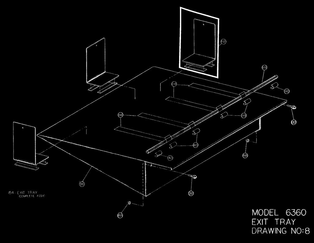
12 DRAWING NO See Drawing Number W-A Exit Tray W-O Paper Guide & Stop 3 M-S Magnet.5 ft. 113 M-S Clamp M-S Strap W-O Rod 1 AA M-S Kep Nut 2 BB M-S Shoulder Screw Complete Exit Tray 1 DRAWING NO See Drawing Number 3 39 See Drawing Number 3 42 See Drawing Number 3 59 See Drawing Number See Drawing Number See Drawing Number M-O Stacker Rack 117 Illustration Number Illustration Number Illustration Number Illustration Number Illustration Number Illustration Number CC 2 M-S X ½ Socket Head Cap Screw M-O Rod M-S Large Spacer M-S Medium Spacer M-S Collar M-S Wheel Illustration Number Illustration Number Illustration Number Illustration Number Illustration Number 36 1 Illustration Number 59 2 XII
13 DRAWING NO. 9 Illustration Number M-O Stacker Control Rod M-O Short Spacer M-O Roller Adjust Rod M-S Stacker Clamp M-S Calibration Scale M-O Right Hand Bearing Block 2 Illustration Number Same as Illustration Number M-O Drive Shaft M-S Stacker Belt W-O Stacker Belt Guide M-S V Stacker Motor Comes with M-S Strain Relief Bushing W-A Power Cord Assembly 110V M-S X1037 Pulley M-S X1037 Belt M-O Stacker Idler Shaft M-O Roller 1 Illustration Number M-S Bearing 4 W-A Roller Support Assembly W-O Guard W-O Stacker Bracket W-A Frame 1 Illustration Number KK 2 Illustration Number LL W-O Motor Cover 1 AA M-S X 3/8 Socket Head Cap Screw 4 BB M-S CC M-S # 8 Flatwasher 10 EE M-S # 8-32 X 1-1/2 Button Head Screw 2 FF M-S ¼-20 X 3 Button Head Screw 2 GG M-S ¼-20 X 3/8 Nut Head Screw 6 HH M-S ¼ Internal Tooth Lockwasher 6 JJ M-S X ½ Socket Head Cap Screw 2 KK M-S Shoulder Screw 2 LL M-S Kep Nut 5 XIII
14 XIV
15 DRAWING NO Frame Assembly W-O Gusset M-S Glide (foot) M-S #10 5/32 Allen Wrench M-S ¼ 3/16 Allen Wrench 1 AA M-S ¼-20 X ½ Socket Head Cap Screw 4 BB M-S #10 Lockwasher 8 CC M-S X 3/8 Socket Head Cap Screw 8 DD M-S ¼ Internal Tooth Lockwasher Stand- Complete XV
16 XVI
HD38, HD58, HD78 REV
 HD38, HD58, HD78 REV. 07.29.2014 COVER for HD38, HD58, HD78 5 P004868 1/4-20x3/4 Button Head Cap Screw Stainless Steel 2 6 P001450 Lockwasher - Internal Tooth.250 6 8 P005200 Wave Disc Washer 4 10 P004869
RYOBI 10 in. TABLE SAW - MODEL NO. BT3000
 FOR MITER TABLE ASSEMBLY, REFER TO FIGURE 0 RYOBI 0 in. TABLE SAW - MODEL NO. BT000 FIGURE 5: 0 in. TABLE SAW FOR BLADE GUARD ASSEMBLY, REFER TO FIGURE FOR RIP FENCE ASSEMBLY, REFER TO FIGURE FOR MOTOR
SPARE PARTS LIST MODEL NO. LB1200F PAGE 1 ITEM PART NO. DESCRIPTION QTY NOTE
 PAGE 1 001 JM21000018 HEX.SOCKET HEAD SCREW M5X12 4 002 JM21000019 SPRING WASHER 5 4 003 JM21000020 FLAT WASHER 5 4 004 JM21000021 UP COVER COMPLETE 1 005 JM21000025 MICRO SWITCH FIX PANEL A 1 006 JM21000026
RYOBI 10 IN (254 MM) TABLE SAW MODEL NO. BT REPAIR SHEET
 TABLE SAW MODEL NO. BT REPAIR SHEET") RYOBI 0 IN (2 MM) TABLE SAW MODEL NO. BT00- REPAIR SHEET 2 RYOBI 0 in. (2 mm) TABLE SAW - MODEL NO. BT00- FOR MITER TABLE ASSEMBLY, REFER TO FIGURE B FOR BLADE GUARD ASSEMBLY, REFER TO FIGURE E FOR RIP
RYOBI 0 IN (2 MM) TABLE SAW MODEL NO. BT00- REPAIR SHEET 2 RYOBI 0 in. (2 mm) TABLE SAW - MODEL NO. BT00- FOR MITER TABLE ASSEMBLY, REFER TO FIGURE B FOR BLADE GUARD ASSEMBLY, REFER TO FIGURE E FOR RIP
Trick-Tools 75 Truman Road Pella, IA Phone:1-877-VAN-SANT
 Distributed by: Trick-Tools 75 Truman Road Pella, IA 50219 Phone:1-877-VAN-SANT E-mail: sales@trick-tools.com Here at Trick Tools we believe that our customers deserve the best value in their tool and
 488 PARTS LIST 1 3 SCREWS FOR NO. 2 2 FLYWHEEL CAP 3 FLYWHEEL 4 END NUT FOR NO. 10 5 BALL BEARING FOR NO. 3 (1 st ) 6 BALLBEARING FOR NO. 3 (2nd) 7A CLUTCH RACE KEY 7B CLUTCH RACE 7C CLUTCH SPRING 7D 7
RYOBI 10 in. (254 mm) TABLE SAW MODEL NO. BT3100 REPAIR SHEET
 TABLE SAW MODEL NO. BT3100 REPAIR SHEET") RYOBI 0 in. (4 mm) TABLE SAW MODEL NO. BT00 REPAIR SHEET FOR MITER TABLE ASSEMBLY, REFER TO FIGURE B FOR BLADE GUARD ASSEMBLY, REFER TO FIGURE E FOR RIP FENCE ASSEMBLY, REFER TO FIGURE C FOR MOTOR ASSEMBLY,
RYOBI 0 in. (4 mm) TABLE SAW MODEL NO. BT00 REPAIR SHEET FOR MITER TABLE ASSEMBLY, REFER TO FIGURE B FOR BLADE GUARD ASSEMBLY, REFER TO FIGURE E FOR RIP FENCE ASSEMBLY, REFER TO FIGURE C FOR MOTOR ASSEMBLY,
Main Breakdown. Model G0531B/G0566B V2 (G0531B) 80V2-2
 80V2-2") Main Breakdown 53 85-1 54 59 54 56 54 52 55 57 175 53 56 85 29 119-2 114 89 22 119-2 119 107 119-5 119-3 119-6 119-1 29 22 119-4 114 112 96 113 114 100 116 117 105 120 102 103 108 115 99 98 92 91 90 73
Main Breakdown 53 85-1 54 59 54 56 54 52 55 57 175 53 56 85 29 119-2 114 89 22 119-2 119 107 119-5 119-3 119-6 119-1 29 22 119-4 114 112 96 113 114 100 116 117 105 120 102 103 108 115 99 98 92 91 90 73
Exploded View Saw Base - Model 7060 Semi-Automatic Cut-Off Band Saw
 Exploded View Saw Base - Model 7060 Semi-Automatic Cut-Off Band Saw 136 137 135 134 132 131 133 113 114 115 117 116 118 119 120 121 79 78 77 107 108 65 76 110 109 66 10 9 6 11 5 4 8 7 75 74 73 72 111 112
RYOBI. 10 in. (254 mm) TABLE SAW MODEL NO. BTS15 REPAIR SHEET
 TABLE SAW MODEL NO. BTS15 REPAIR SHEET") RYOBI 0 in. ( mm) TABLE SAW MODEL NO. BTS REPAIR SHEET FIGURE A 0 0 0 0 The model number will be found on a plate attached to the motor housing. Always mention the model number in all correspondence regarding
RYOBI 0 in. ( mm) TABLE SAW MODEL NO. BTS REPAIR SHEET FIGURE A 0 0 0 0 The model number will be found on a plate attached to the motor housing. Always mention the model number in all correspondence regarding
ST1014 PARTS ST1014 Headstock Breakdown
 ST1014 PARTS ST1014 Headstock Breakdown 112 114 23 104 105 108 102 106 20 19 21 22 101 100 103 111 38 14 15 37 46 44 47 45 107 93 39 41 40 67 110 109 74 75 76 11 12 13 9 8 6 10 31-2 31-3 3 2 7 26 24 31-1
1822-I. Spindle Assembly. Pipe and Bolt Threading Machine. Ridge Tool Company/Elyria, Ohio, U.S.A. 2* 3 4 5* * *
 -I Pipe and Bolt Threading Machine Spindle Assembly * * * 0 * * * 0 * * 0* * * Rear Cover * Screw () * Washer () Top Cover w/clips (Includes,, ) * J Clip () Front Cover * Screw () Pivot Rod Support ()
25-200H. 12 Planer / Jointer. with Helical Cutterhead. Parts List.
 25-200H 12 Planer / Jointer with Helical Cutterhead 4001824 Parts List www.rikontools.com CABINET ASSEMBLY PARTS EXPLOSION & PARTS LIST KEY NO. DESCRIPTION KEY NO. DESCRIPTION 1 Pan Head Screw M6x12 P25-200H-1
Parts List: Head Assembly
 Head Assembly 23 Parts List: Head Assembly Index No. Part No. Description Size Qty 1...JWP15H-001... Head Casting......1 2...TS-1525021... Set Screw... M10x12...8...JWP15DX-CA... Cutter Head Assembly (Index
Operating Instructions and Parts Manual. 10 x 16 Horizontal Band Saw Models J-7020, J-7040
 Operating Instructions and Parts Manual 10 x 16 Horizontal Band Saw Models J-7020, J-7040 JET 427 New Sanford Road LaVergne, Tennessee 37086 Part No. M-414472 Ph.: 800-274-6848 Revision C2 03/2014 www.jettools.com
BASE, COLUMN, ARM AND TABLE
 SPARE S LIST Item No. 700000 Article No. 84-2265 IMPORTANT INSTRUCTIONS It is most important that the above illustration be studied prior to the assembly of the saw blade and arbor or the assembly of the
G0513X2 Main -87- G0513 Series Bandsaws 82V V2 82-6V2 95A V2 82-5V2 82-1V2 82-4V V A
 G0513X2 Main 23 55 22 48 17 17-1 17-2 21 7 17-3 17-2 17-4 24 17-5 18-5 22 24 21 55A 50 8 9 49 11 12 13 14 15 47 16 10 46 45 3 44 43 39 38 37 39 40 32 33 36 42 34 35 2 25 28 18-4 18-2 18-3 31 30 29 18-1
HYDRAULIC CONTROL DETAILS PARTS LIST
 Always give model number, serial number and part number when ordering repair parts. HYDRAULIC CONTROL DETAILS PARTS LIST REF NO. PART NUMBER DESCRIPTION 1 101939 Hydraulic Tank 2 101940 Hydraulic Tank
CATALOG OF REPLACEMENT PARTS
 CATALOG OF REPLACEMENT PARTS HS4N SLICER ML-136338 HS4N A product of HOBART 701 S. RIDGE AVENUE TROY, OHIO 45374-0001 FORM 43311 (August 2015) F-43311 (August 2015) - 2 - HOBART 2015 Table of Contents
MODEL NO.: MI PARTS BREAKDOWN
 MODEL NO.: MI-76350 PARTS BREAKDOWN MAGNUM DRILL PRESS ASSEMBLY INSTRUCTIONS MODEL MI-76350 Before you begin to assemble your drill press, review the parts breakdown and keep it ready for reference. Start
535A. Main Components. Pipe and Bolt Threading Machine. Printed in U.S.A. Ridge Tool Company/Elyria, Ohio, U.S.A.
 Pipe and Bolt Threading Machine A Main Components 0 Screw, Button Head /" - 0 x /" () Washer, Flat /" ()" Top Cover 0 Base Bottom Cover Screw, Pan Head # - x " () Carriage Assembly 0 Front Support Bar
SECTION 9: PARTS Main
 SECTION 9: PARTS Main 58 63 67 66 65 67 66 59 58 49 58 48 49 61A 61 64 62 55 50 35-3 34 35-1 57 56 41 42 151 51 50 33A 35-2 30A 30A-1 35 38 39 31 32 18 40 43 44 68 51 41 45 46 57 56 55 47 152 153 20 21
MODEL RA-2500N RADIAL ARM SAW
 1 6130089 HEX. NUT (L.H.T.) W5/8"-18UNF 2.18 2 6900549 WASHER 1.78 3 6080529 ARBOR COLLAR 31.02 4 6760117 OILLESS METAL 1.57 5 9270612 CLAMP SCREW M6 X 12 0.19 6 9220625 HEX. SOCKET HEAD BOLT M6 X 25 0.22
CATALOG OF REPLACEMENT PARTS
 The Choice of Experience CATALOG OF REPLACEMENT PARTS MODELS 909A 919A 909E 919E 909M 919M SLICERS EFFECTIVE MARCH 2009 - 2 - Table of Contents 5 ELECTRICAL COMPONENTS (909A & 919A) 7 ELECTRICAL COMPONENTS
SPARE PARTS LIST MODEL NO PAGE 1 ITEM PART NO. DESCRIPTION QTY NOTE
 PAGE 1 001 342186-7 SWITCH PROTECTOR 1 002 911118-1 PAN HEAD SCREW M4X12 6 003 155512-9 SWITCH PLATE 1 004 651757-2 SWITCH ABK266 1 006 685712-2 SPONGE SHEET 60X60 1 007 911118-1 PAN HEAD SCREW M4X12 1
SECTION 9: PARTS. Table Breakdown REF PART # DESCRIPTION REF PART # DESCRIPTION
 SECTION 9: PARTS Table Breakdown 1 2 3 4 5 6 7 8 9 10 11 12 13 14 15 16 17 18 19 20 21 22 23 24 23 25 17 26 27 8 1 P0675001 CAP SCREW M8-1.25 X 30 15 P0675015 SUPPORT BLOCK 2 P0675002 TABLE SUPPORT BLOCK
PARTS Stand Breakdown
 PARTS Stand Breakdown 35-5 35-2 35-4 63 1 2 3 4 5 35-1 35-3 36 37 38 39 35 34 33 32 30 28 6 7 8 21 29 23 22 27 26 25 24 42 43 44 45 46 47 9 10 62 61 60 51 11 59 19 18 12 12 13 58 14 57 15 56 55 54 53 52
SECTION 9: PARTS. Headstock A 126A 127A-1 REF PART # DESCRIPTION REF PART # DESCRIPTION
 SECTION 9: PARTS Headstock 120 121 113 115 112 111 110 109 108 105 106 107 135 101 119A 121 120 118 114 115 107 106 104 123 122 118 114 126A 105 126 103 102 126B 127A-1 131 127A 124 133 134 126C 129 130
CATALOG OF REPLACEMENT PARTS
 CATALOG OF REPLACEMENT PARTS HL300 SERIES LEGACY MIXER ML-134351 ML-134358 ML-141097 HL300 HL300C HL300 (Canada) A product of HOBART 701 S. RIDGE AVENUE TROY, OHIO 45374-0001 FORM 43136 Rev. C (July 2017)
Repair Parts. Parts List for RIDGID 10 Inch Table Saw Model No. TS Figure 1. RIDGID parts are available on-line at
 Parts List for RIDGID 0 Inch Table Saw Model TS00 Figure 0 0 0 0 See Figure 0 See Figure 0 See Figure Parts List for RIDGID 0 Inch Table Saw Model TS00 Figure Always Order by Part Number - not by Number
SECTION 10: PARTS Body
 -76- Model G0690/G0691 (Mfd. 6/15+) SECTION 10: PARTS 55V2 55-1 55-2 55-3V2 55-5 55-6 8 9 9 56 10 10 68 69 70 71 55-4 1 2 3 4 5 6 7 8 9 14 15 18 19 20 21 22 23 24 25 26 27 27 28 29 30 31 32 32 33 33 34
RYOBI 10 in. TABLE SAW MODEL NO. BTS16 REPAIR SHEET
 RYOBI 0 in. TABLE SAW MODEL NO. BTS REPAIR SHEET FIGURE A FIGURE E FIGURE H FIGURE C FIGURE D 0 0 FIGURE B 0 0 NOTE A WARNING: Improper electrical repair of the table saw can result in damage to the drive
CATALOG OF REPLACEMENT PARTS
 CATALOG OF REPLACEMENT PARTS 3000 SERIES AUTOMATIC SLICERS 3713 ML-136144 3713 (Canada) ML-136177 3713N ML-136181 3713N (Canada) ML-136184 3913 ML-136145 3913 (Canada) ML-136179 3913N ML-136183 3913N (Canada)
CATALOG OF REPLACEMENT PARTS
 CATALOG OF REPLACEMENT PARTS MODEL X13 SERIES SLICER FORM 43180 Rev. A (April 2013) F-43180 Rev. A (April 2013) - 2-2013 Table of Contents 5 ELECTRICAL COMPONENTS 7 RING GUARD AND CENTER PLATE 9 ARM ASSEMBLY
TP1300 OWNER S MANUAL
 TP00 OWNER S MANUAL INCH THICKNESS PLANER For Your Safety: Read all instructions carefully Save this manual for future reference SP PrintedinTaiwan Parts List for " Thickness Planer Model. TP00 Figure
Section A Gear Box September A
 Section A Gear Box September 06 1A Index 1. 1-10016-000 Gear Box Oil Pan. 1-100486-000 Clutch Lever Assembly, See Page 9A for breakdown. 1-1004-000 Clutch Cam, for all A machines prior to Serial #5 1-104-000
SECTION 8: PARTS Main Parts Breakdown
 SECTION 8: PARTS 10 Main Parts Breakdown 6 1 7 9 2 4 8 15 60 61 62 63 64 110 11 12 13 18 19 21 17 22 23 24 27 14 25 34 65 35 66 67 83 84 36 37 68 69 85 70 80 86 38 73 81 87 89 82 90 71 72 74 91 79 88 92
Coolant Tank Screen Leg Idle End Lockwasher 64 B-015B Leg Drive End Machine Screw 1/4-20 x 3/4 Round Head
 Always give model number, serial number and part number when ordering repair parts. BED, COOLANT & DASH POT PARTS LIST (Cont'd.) REF NO. PART NUMBER DESCRIPTION 19 B-077 Vise Slide Block 20 B-045 Vise
Main Drive Components
 Pipe and Bolt Threading Machine Main Drive Components 0 0 Rear Centering Head Centering Jaw Set Spiral Pins () 00 Centering Scroll Retaining Ring 0 Rear Bearing 0 Oil Ball Valve () # - x / Screw Motor
FRICTION PARTS SECTION 11-1 TP10449 ASSEMBLY NUMBER: 714 FRICTION FEED FOLDER DESCRIPTION: REV: BAUMFOLDER CORPORATION UNIT NAME:
 SECTION - TP0449 FRICTION PARTS 74 FRICTION FEED FOLDER 74 SHEET OF TP0449 SECTION - 4 3 6 5 TOP LEVEL UNIT 60HZ 74 FRICTION FEED FOLDER 74F--F- SHEET OF 74F--F- FRAME PAR 74 FRICTION 43-097A GAPSETS,
EXCERPT FROM THE Jobsite saw OWNERS MANUAL
 Table and Fence Table and Fence Parts List 0 0 0 0 0 0 0 0 Table JSS-00 Fence Roller Pin (mm x mm) JSS-0 Rear Lock Down Screw for Insert JSS-00 0 mm O-Ring JSS-00 Extension Wing JSS-00 Fence Roller Wheel
3000, 4000, 4100, 7500, 7700
 3000, 4000, 4100, 7500, 7700 Drum & Disc Brake Lathes s Identification READ these instructions before placing unit in service. KEEP these and other materials delivered with the unit in a binder near the
535-Manual. Main Components. Pipe and Bolt Threading Machine. Printed in U.S.A. Ridge Tool Company/Elyria, Ohio, U.S.A.
 Pipe and Bolt Threading Machine -Manual Main Components 0 Screw, Button Head /" - 0 x /" () Washer, Flat /" ()" Top Cover 0 0 Cutter Assembly Stop Pin 0 Pin Reamer Assembly Carriage Assembly 0 Stop Screw
SECTION 9: PARTS G0513/G0513P/G0513ANV
 SECTION 9: PARTS G0513/G0513P/G0513ANV Main 21 22 23 82-6 82-5 48 22 19 20 24 18 17 24 17 26 21 55 17 16 14 15 32 33 34 20 18 27 25 50 13 47 18 82-1 175 35 55A 49 9 11-1 10 46 45 11 12 44 176 39 38 37
CATALOG OF REPLACEMENT PARTS
 CATALOG OF REPLACEMENT PARTS HL400 SERIES LEGACY MIXER ML-134348 ML-134359 ML-141096 HL400 HL400C HL400 (Canada) A product of HOBART 701 S. RIDGE AVENUE TROY, OHIO 45374-0001 FORM 43137 Rev. A (May 2016)
PARTS LIST MODEL: HDEJ1800
 First Edition: June 0 PARTS LIST 0 8 4 8 8 4 8 0 KEY PARTS NO. NO. DESCRIPTION 0400 Top cover (unit) 00 Top cover (unit) 0000 Top cover 4 40A04 Flip-top sewing instruction panel 000 Hinge rod (right) 00
IMPORTANT: Chuck guard MUST be installed before drill chuck!
 IMPORTANT: Chuck guard MUST be installed before drill chuck! Model G7945/G7946 ***IMPORTANT UPDATE*** For Machines Mfg. Since December, 2012 and Owner's Manual Revised August, 2009 The following changes
EEBR312A Brake Lathes Parts Identification
 EEBR312A Brake Lathes s Identification READ these instructions before placing unit in service. KEEP these and other materials delivered with the unit in a binder near the machine for ease of reference
CATALOG OF REPLACEMENT PARTS
 CATALOG OF REPLACEMENT PARTS FMS30 MIXER ML-134462 ML-134463 FORM 43181 Rev. A (April 2014) F-43181 Rev. A (April 2014) - 2-2014 Table of Contents 5 CONTROL PANEL 7 ELECTRICAL COMPONENTS 9 ATTACHMENT HUB
M1014 7" x 12" Metal Cutting Bandsaw PARTS -38-
 14 13 15 16 18 17 55 10 12 11 19 54 9 20 53 7 5 4 60 7 3 1 28 6 2 61 23 27 26 29 21 24 25 22 32 32 33 35 36 37 38 49 48 47 40 39 34 30 59 51 52 46 45 44 43 42 42 41 50 56 57 58-38- Parts List 1 XM1014001
Section F SETTING TABLE
 Section F SETTING TABLE December 2009 1F Index No. Part No. Description 1. 47-051635-001 Geared Rack 2. 11-051880-001 N.A. Truss Hd. Machine Screw (6 mm x 16 mm) 47-861008-001 R.O. Truss Hd. Machine Screw
Parts List: VBS-3612 Band Saw
 Parts List: VBS-3612 Band Saw (refer to breakdowns on pages 35 and 36) Index No. Part No. Description Size Qty 1... VBS3612-101...Gear Box... 1 2... TS-0209101...Socket Head Cap Screw...3/8-16 x 2-1/4...
CATALOG OF REPLACEMENT PARTS
 CATALOG OF REPLACEMENT PARTS FMS20 MIXER WITH ATTACHMENT HUB ML-134387 ML-134388 WITHOUT ATTACHMENT HUB ML-134398 ML-134399 FORM 43166 (September 2016) F-43166 (September 2016) - 2-2016 Table of Contents
SECTION 9: PARTS G0453Z
 parts breakdown SECTION 9: PARTS G0453Z Headstock Breakdown 4 3 2 20 26 104 21 19 23 22 24 99 97 98 25 94 95 93 14 15 39 40 107 86 41 42 45 62 30 66 61 60 13 9 10 12 11 27 31 33 34 35 73 77-1 77 36 3738
3000, 4000, 4100, 7500, 7700 Drum & Disc Brake Lathes
 3000, 4000, 4100, 7500, 7700 Drum & Disc Brake Lathes Model 4000 Shown Parts Identification READ these instructions before placing unit in service. KEEP these and other materials delivered with the unit
PARTS G9729 Lathe Bed
 PARTS G9729 Lathe Bed 114 132 126 125 131 133 129 128 130 127 139 124 10 124 123 122 135 137 147 144 121 148 146 149 136 138 140 150 152 142 143 141 151 153 21 168 20 19 18 17 162 22 147 13315 14 13131
SECTION 9: PARTS Main
 63 58 62 61A 66 65 67 66 67 58 58 59 64 SECTION 9: PARTS 162 161 Main 160 45 152 21 20 17 153 166 33 30A 31 32 135 144 133 136 34 35-2 35-3 131 16 130 134 139 15 35-1 137 14V2 151 140 38 143 150 18 142
SECTION 9: PARTS Cabinet & Base
 SECTION 9: PARTS 5 5-1 48 3 75 90 49 4 91 333 46 47 30 89 88 2 34 33 37 36 78 35 32 326 316 49 42 45 83 84V2 43 1 7 8 9 12 87 10 11 Cabinet & Base 31 17 20 40 39 136 41 135 85 86 8 28 26 18 19 21 19 370
3000, 4000, 4100, 7500, 7700
 3000, 4000, 4100, 7500, 7700 Drum & Disc Brake Lathes Model 4000 Shown s Identification READ these instructions before placing unit in service. KEEP these and other materials delivered with the unit in
SECTION 9: PARTS. Electrical REF PART # DESCRIPTION REF PART # DESCRIPTION
 SECTION 9: PARTS Electrical 1 P4002001 START BUTTON 52 P4002052 CONTACTOR GSC1CJX4-D 110V 2 P4002002 INDICATOR LIGHT 53 P4002053 CONTACTOR JZC3-40D 110V 3 P4002003 JOG BUTTON 54 P4002054 FUSE HOLDER 4
Disc, Belt, and Combination Disc/Belt Sanders
 This Manual is Bookmarked Operating Instructions Parts Manual Disc, Belt, and Combination Disc/Belt Sanders Models: 4200A, 4300A, 4400A 4200A Disc/Belt Sander 4300A 6 Inch Belt Sander 4400A 12 Inch Disc
Number Wheeler P/N Description Set Rex P/N Notes Base 1 J Support, Right 1 J Support, Left 1 J Nut (M8)
") 1 603500 Base 1 J001 2 603501 Support, Right 1 J002 3 603502 Support, Left 1 J003 4 600328 Nut (M8) 4 5 600130 Spring Washer (8mm) 4 6 600344 Roll Pin (M6x30) 4 7 600129 Socket Hd Cap Screw (M8x25) 4 8
1 603500 Base 1 J001 2 603501 Support, Right 1 J002 3 603502 Support, Left 1 J003 4 600328 Nut (M8) 4 5 600130 Spring Washer (8mm) 4 6 600344 Roll Pin (M6x30) 4 7 600129 Socket Hd Cap Screw (M8x25) 4 8
CATALOG OF REPLACEMENT PARTS
 CATALOG OF REPLACEMENT PARTS FMS40 MIXER ML-134476 ML-134477 ML-141002 FORM 43182 Rev. A (April 2014) F-43182 Rev. A (April 2014) - 2-2014 Table of Contents 5 CONTROL PANEL 7 ELECTRICAL COMPONENTS 9 ATTACHMENT
TP1300 OWNERS MANUAL 13 INCH THICKNESS PLANER WITH LEGSET. For Your Safety: Read all instructions carefully Save this manual for future referenece
 TP00 OWNERS MANUAL INCH THICKNESS PLANER WITH LEGSET For Your Safety: Read all instructions carefully Save this manual for future referenece SP Printed in Taiwan Parts List for " Thickness Planer Model
GEAR HEAD METAL LATHE
 GEAR HEAD METAL LATHE MODEL G4002 / G4003 PARTS LIST COPYRIGHT 2000 BY GRIZZLY INDUSTRIAL, INC. WARNING: NO PORTION OF THIS MANUAL MAY BE REPRODUCED IN ANY SHAPE OR FORM WITHOUT THE WRITTEN APPROVAL OF
Page 1 Parts List for AL-51G (L160) 07/08/201. Headstock Assembly
 07/08/201. Headstock Assembly") Page 1 Parts List for AL-51G (L160) 07/08/201 Headstock Assembly 1--------1002-------------------Headstock Casting 13-------1012------------------------------Nut M28 2--------1006---------------------------Flange
Page 1 Parts List for AL-51G (L160) 07/08/201 Headstock Assembly 1--------1002-------------------Headstock Casting 13-------1012------------------------------Nut M28 2--------1006---------------------------Flange
Model W1819/W1820 (Mfg. Since 09/11) PARTS. Body V V PARTS -79-
 PARTS. Body V V PARTS -79-") -79- Model W1819/W1820 (Mfg. Since 09/11) 155V2 155-1 155-2 155-3V2 155-6 155-5 108 109 109 156 110 110 168 169 170 171 101 102 103 104 105 106 107 108 109 114 115 118 119 120 121 122 123 124 125 126 127
-79- Model W1819/W1820 (Mfg. Since 09/11) 155V2 155-1 155-2 155-3V2 155-6 155-5 108 109 109 156 110 110 168 169 170 171 101 102 103 104 105 106 107 108 109 114 115 118 119 120 121 122 123 124 125 126 127
YAO HAN 耀瀚股份有限公司 YA O H A N I N D U S T R I E S C O., LT D. 手提式縫口袋機 YA O H A N I N D U S T R I E S C O., LT D.
 耀瀚股份有限公司 YA O H A N I N D U S T R I E S C O., LT D. YAO HAN MODEL ONE THREAD F300A ( 單線 ) TWO THREAD F302A ( 雙線 ) 手提式縫口袋機 PORTABLE BAG CLOSER PARTS BOOK 零件本 2005.09.26 耀瀚股份有限公司 YA O H A N I N D U S T R
W1812 Owner's Manual (Mfd. Since 02/11) PARTS. Headstock 11V2 30V2 95V V2 8 25V2 41V2 25V2 23V2 27V2 PARTS -45-
 PARTS. Headstock 11V2 30V2 95V V2 8 25V2 41V2 25V2 23V2 27V2 PARTS -45-") -45- Headstock 20 21 23V2 8 25V2 23V2 25V2 26 28 87 88 57 56 40 47 39 39 37 46 33 34 42 63 13 2 93 93 71 70 69 17 41V2 92 30V2 31 32 7 38 35 33 34 37 40 43 16 11V2 1 4 5 9 61 62 61 62 18 10 3 8 19 14 95V2
-45- Headstock 20 21 23V2 8 25V2 23V2 25V2 26 28 87 88 57 56 40 47 39 39 37 46 33 34 42 63 13 2 93 93 71 70 69 17 41V2 92 30V2 31 32 7 38 35 33 34 37 40 43 16 11V2 1 4 5 9 61 62 61 62 18 10 3 8 19 14 95V2
Upper Wheel Assembly Exploded View
 Upper Wheel Assembly Exploded View 36 Upper Wheel Assembly Parts List Index No. Part No. Description Size Qty 1... JWBS18-135...Hex Nut...5/8-18UNF, LH... 1 2... PM1800-102...Flat Washer... 1 3... BB-6204VV...Ball
PARTS LIST: Air Control Assembly (1632 Sander)
") PARTS LIST: Air Control Assembly (1632 Sander) 1 6293482 Filter... 1 2 6293483 Solenoid Valve... 1 3 6293484 Brake Cylinder... 1 4 6293485 Multi-Hole Connector... 1 5 6293486 Air Valve... 1 6 6293487 Air
PARTS LIST: Air Control Assembly (1632 Sander) 1 6293482 Filter... 1 2 6293483 Solenoid Valve... 1 3 6293484 Brake Cylinder... 1 4 6293485 Multi-Hole Connector... 1 5 6293486 Air Valve... 1 6 6293487 Air
Note: Parts without part numbers are for reference only and cannot be purchased individually.
 Parts Ordering Replacement Parts To order parts or reach our service department, call 1-800-274-6848 between 7:30am and 5:30pm (CST), Monday through Friday. Having the Model Number and Serial Number of
Parts list. From Product number xx MARCH SVP Worldwide - All rights reserved.
 Parts list 01 SVP Worldwide - All rights reserved. From Product number 971-xx 0 MARCH 01 A 1 9 7 8 10 1 11 1 1 1 19 18 17 1 0 1 1 7 8 0 1 1 9 1 19810 PRE -TENSION UNIT 17901 REEL PIN 1701 SPRING, REEL
How to program the digital speed display (This is factory set and will only need to be programmed if the unit is replaced)
") How to program the digital speed display (This is factory set and will only need to be programmed if the unit is replaced) 1. Press and hold the set button (top left corner) until the display shows Fun
How to program the digital speed display (This is factory set and will only need to be programmed if the unit is replaced) 1. Press and hold the set button (top left corner) until the display shows Fun
Main Parts. -6- Model G0555LA35 (Mfd. Since 10/17) 30A V
 30A V") 60 49 50 76 41 65 66 44 46 43 42 47 51 63 58 64 59 48 62 16 61V2 50 51 55 56 57 70 49 69 64 55 56 43 57 167 154 41 40 8 22 30A 44 45 3 4 Main Parts 14 15 16 7 168 155 30 195 34 194 186 6 68 24 115 116
60 49 50 76 41 65 66 44 46 43 42 47 51 63 58 64 59 48 62 16 61V2 50 51 55 56 57 70 49 69 64 55 56 43 57 167 154 41 40 8 22 30A 44 45 3 4 Main Parts 14 15 16 7 168 155 30 195 34 194 186 6 68 24 115 116
MODEL G0501 SLIDING TABLE SAW
 MODEL G0501 SLIDING TABLE SAW MANUAL UPDATE The Sliding Table Saw has changed slightly from when the manual was originally written. We have improved the crosscut fence, extension tables, blade guard assembly,
Model G " Planer/Moulder -33- G0477 Body Breakdown
 Model G0477 15" Planer/Moulder -33- G0477 Body Breakdown 202 200 201 203 204 194 192 193 195 205 141 143 196 197 142 148 146 178 183 154 155 198 199 144 145 153 157 159 158 181 182 188 185 184 187 186
INDEX. 52SD Mower Deck Shell, Pulley Covers, Gauge Wheels and Attaching Parts Pulleys, Blades, Belts, Spindles and Attaching Parts...
 R Ingersoll HOME TRACTORS 52SD, 62SD and 72SD INDEX 52SD Mower Deck Shell, Pulley Covers, Gauge Wheels and Attaching Parts... 3 Pulleys, Blades, Belts, Spindles and Attaching Parts... 5 62SD Mower Deck
SECTION 9: PARTS. Table. Spiral Cutterhead For Model G0452Z Cutterhead For Models G0452/P Model G0452/P/Z (Mfg.
 SECTION 9: PARTS Table 17 18 19 87 86 21 262-3 262-1 262-2 27 28 29 30 22 23 24 35 36 37 38 262 25 26 2 13 Cutterhead For Models G0452/P 10 45 12 13 7 8 9 50A 6 11 31 14 15 16 12 13 81 82 83 84 32 85 33
SECTION 9: PARTS. Electrical Box. (0000 Series Parts) 0000 Series Parts List
 0000 Series Parts List") SECTION 9: PARTS Electrical Box (0000 Series Parts) 0000 Series Parts List 1 P04920001 CONTACTOR 6 P04920006 FUSE 2A (LC1-D0910, B5, 24V, 50HZ) 7 P04920007 FUSE HOUSING 2 P04920002 CONTACTOR 8 P04920008
SECTION 9: PARTS Electrical Box (0000 Series Parts) 0000 Series Parts List 1 P04920001 CONTACTOR 6 P04920006 FUSE 2A (LC1-D0910, B5, 24V, 50HZ) 7 P04920007 FUSE HOUSING 2 P04920002 CONTACTOR 8 P04920008
SECTION 9: PARTS Table
 SECTION 9: PARTS Table 33 We do our best to stock replacement parts when possible, but we cannot guarantee that all parts shown are available for purchase. Call (800) 523-4777 or visit www.grizzly.com/
MODEL G0760 8" X 29" MILL/DRILL w/stand & POWER FEED MANUAL INSERT
 MODEL G0760 8" X 29" MILL/DRILL w/stand & POWER FEED MANUAL INSERT The Model G0760 is the same machine as the Model G0705 except the Model G0760 has an X-axis table power feed. Except for the differences
G0513X2 Main. G0513 Series Bandsaws (Mfd. Since 07/18) A V2
 A V2") G0513X2 Main 55 17 48 7 16 55A 14 15 49 13 47 50 12 10 71 70 72 73 59 69 74 46 11 9 8 76 5 75 4 68 81 80 67 66 48 50 39 78 79 23 17-3 17-2 17-1 17-4 17-2 21 22 24 17-5 32 33 34 35 28 2 45 3 38 44 39 43
G0513X2 Main 55 17 48 7 16 55A 14 15 49 13 47 50 12 10 71 70 72 73 59 69 74 46 11 9 8 76 5 75 4 68 81 80 67 66 48 50 39 78 79 23 17-3 17-2 17-1 17-4 17-2 21 22 24 17-5 32 33 34 35 28 2 45 3 38 44 39 43
CATALOG OF REPLACEMENT PARTS
 CATALOG OF REPLACEMENT PARTS MODEL 4246 MIXER-GRINDERS 4246S 4246HD 4246S 4246S 4246HD 4246HD STANDARD (5 HP./1 HP.) ML-134220 HEAVY DUTY (7.5 HP./1 HP.) ML-134221 PRIOR MLS COVERED IN THIS MANUAL STANDARD
J-3-D PART NO DATE:
 37-380 & 37-877 8 PROFESSIONAL JOINTER J-3-D PART NO. 909563 DATE: 05-12-04 Page1/ J-3-D /DEB REPLACEMENT PARTS * 1345487 CUTTERHEAD ASSY, INCL: 1 1340196 KNIFE SCREW 2 1345488 BAR 3 37-355 KNIVES (SET
Parts Manual. Models 521 SSE (621502X37NA) 521 SSR (621503X37NA) &
 521 SSR (621503X37NA) &") Parts Manual Models 521 SSE (621502X37NA) 521 SSR (621503X37NA) 1740273 & 1740275 11.2006 Table Of Contents PRODUCT COMPONENTS PAGES Handle Group... 4 Engine Group... 6 Frame Group... 8 Auger Housing
Parts Manual Models 521 SSE (621502X37NA) 521 SSR (621503X37NA) 1740273 & 1740275 11.2006 Table Of Contents PRODUCT COMPONENTS PAGES Handle Group... 4 Engine Group... 6 Frame Group... 8 Auger Housing
READ THIS FIRST. For questions or help with this product contact Tech Support at (570) or
 or") READ THIS FIRST Model G4002/G4003 ***IMPORTANT UPDATE*** For Machines Mfd. Since December, 2014 and Owner's Manual Printed April, 2014 For questions or help with this product contact Tech Support at (570)
READ THIS FIRST Model G4002/G4003 ***IMPORTANT UPDATE*** For Machines Mfd. Since December, 2014 and Owner's Manual Printed April, 2014 For questions or help with this product contact Tech Support at (570)
32 FRONT DECK ASSEMBLY
 3 6 K 2 0 PARTS MANUAL 32 FRONT DECK ASSEMBLY 3 1 2 Belt Shield Prior to SN 33333 4 6 21 22 7 24 2 26 14 8 13 12 9 10 11 27 2 28 1 16 2 19 17 30 36 39 39 37 29 60 62 61 3 9 49 41 40 28 48 42 13 43 44 47
Parts List Index No. Part No. Description Size Qty
 Parts List Index No. Part No. Description Size Qty 1... TS-1541031...Lock Nut...M8... 4 2... JJP12-002...Washer... 4 3... JJP12-003...Outfeed Table Bracket Shaft... 1 4... JJP12-004...Outfeed Table Bracket,
Upper Wheel Assembly Index No. Part No. Description Size Qty
 Upper Wheel Assembly 1... JWBS16B-101...Saw Body... 1 2... TS-0152011...Carriage Bolt...5/16-18x1... 6 3... JWBS18-103...Upper Wheel Bracket... 2 4... TS-0680031...Flat Washer...5/16... 6 5... TS-0720081...Lock
WELDING POSITIONER PARTS BREAKDOWN DRAWING GP-200
 WELDING POSITIONER PARTS BREAKDOWN 10 DRAWING GP-200 1 GP-200-001 FRAME 1 2 GK-160-012 5/16"-18UNC x 5/8" CARRIAGE BOLT 6 3 GK-136-055 5/16"Ø LOCK WASHER 6 4 GK-109-052 5/16"-18UNC HEX NUT 10 5 GP-200-002
SECTION 9: PARTS Headstock Case and Shift
 SECTION 9: PARTS Headstock Case and Shift 3 1 2 10-1 10-2 8 9 10 6 7 19 10-3 15 11 12 25 16 17 18 14 13 12 32 26 29 20 21 33 34 27 35 37 28 43 22 38 39 40 31 45 28 43 23 41 5 28 43 44 30 36-80- Model G0709
PARTS LIST. Clarke CDP350V 16mm DRILL PRESS Part Number:
 PARTS LIST Clarke CDP350V 16mm DRILL PRESS Part Number: - 6500267 Quantity Description Part Number 1 Base DD13301001F 1 Column support DD13401002 1 Hex bolt M10 X30MM N/A 1 Hex setscrew M8X 8 N/A 1 Handlebar
Parts Breakdown 2030N
 Page 1 of 8 8/18/2010 Page 2 of 8 8/18/2010 Page 3 of 8 8/18/2010 Products with multiple versions are listed in subsiding order with the newest version on top not indented Fig # Part ID Part Name Quantity
15" PLANER MODEL G1021Z PARTS LIST
 15" PLANER MODEL G1021Z PARTS LIST COPYRIGHT 2000 BY GRIZZLY INDUSTRIAL, INC. WARNING: NO PORTION OF THIS MANUAL MAY BE REPRODUCED IN ANY SHAPE OR FORM WITHOUT THE WRITTEN APPROVAL OF GRIZZLY INDUSTRIAL,
MODEL W " PLANER PARTS LIST. Phone: On-Line Technical Support:
 MODEL W1692 15" PLANER PARTS LIST Phone: 1-360-734-3482 On-Line Technical Support: tech-support@shopfox.biz COPYRIGHT AUGUST, 2003 BY WOODSTOCK INTERNATIONAL, INC. WARNING: NO PORTION OF THIS MANUAL MAY
 2705 03-09 99 98 97 82 88 89 83 84 85 86 87 101 103 100 106 81 71 105 104 73 74 75 76 77 78 80 79 57 62 58 56 63 65 66 67 68 64 69 70 59 60 61 31 30 29 32 34 35 41 40 42 36 37 38 39 43 4445 46 33 55 54
PARTS. Base Cabinet & Motor PARTS. Model W1745W (For Machines Mfd. Since 9/16) V2 22V2-3 22V2-4 22V2-1 22V2-2
 V2 22V2-3 22V2-4 22V2-1 22V2-2") Model W1745W (For Machines Mfd. Since 9/16) Base Cabinet & Motor 22V2-1 22V2-2 22V2-5 22V2-9 22V2-8 22V2-7 22V2-6 22V2-3 22V2-4 22V2 23 24 26 25 46 47 48 49 44 45 15 14 16 17 50 18 13 12 11 7 20 9 8 9
Model W1745W (For Machines Mfd. Since 9/16) Base Cabinet & Motor 22V2-1 22V2-2 22V2-5 22V2-9 22V2-8 22V2-7 22V2-6 22V2-3 22V2-4 22V2 23 24 26 25 46 47 48 49 44 45 15 14 16 17 50 18 13 12 11 7 20 9 8 9
SAVE THIS MANUAL FOR FUTURE REFERENCE. WARNING: To reduce the risk of
 - ($ 0$$/ PP-,( /$( WARNING: To reduce the risk of injury, the user must read and understand the operator's manual before using this product. Part SP SAVE THIS MANUAL FOR FUTURE REFERENCE Printed in Taiwan
READ THIS FIRST. For questions or help with this product contact Tech Support at (570) or
 or") READ THIS FIRST Model G0811 ***IMPORTANT UPDATE*** For Machines Mfd. Since 02/16 and Owner's Manual Printed 11/16 For questions or help with this product contact Tech Support at (570) 546-9663 or techsupport@grizzly.com
READ THIS FIRST Model G0811 ***IMPORTANT UPDATE*** For Machines Mfd. Since 02/16 and Owner's Manual Printed 11/16 For questions or help with this product contact Tech Support at (570) 546-9663 or techsupport@grizzly.com