Swift assembly guide
|
|
|
- Hugo Carr
- 5 years ago
- Views:
Transcription

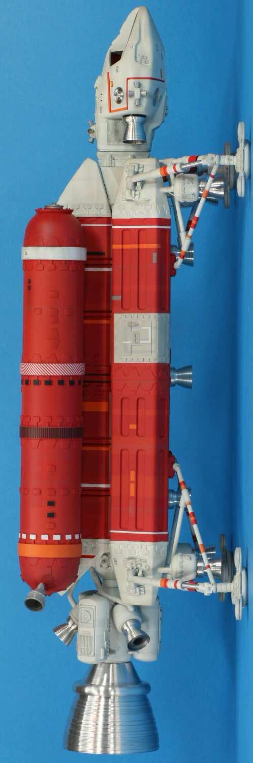
 Shown here without main tanks")
1 Swift assembly guide Download the assembly guide at Sample kit shown with aluminium bells (available with the Deluxe kit) Shown here without main tanks Version 10/12/2010 Page 1
 Plus 15 bells and sensors in aluminium")
 Version 10/12/2010")
2 This kit contains 106 resin parts (colour may vary) Plus 15 bells and sensors in aluminium (Deluxe kit) or resin (Standard kit) (Parts shown with a red X are not included) Version 10/12/2010 Page 2
 soapy water and let them dry. This step is necessary to remove the mould release agent used during casting.")
3 Plus brass and aluminium rods and tubes, wires and decals (not shown) Working with resin Resin dust is harmful to your lungs so wear a protective mask when sanding. Wet sanding is recommended. Before handling resin parts wash them in warm (not hot) soapy water and let them dry. This step is necessary to remove the mould release agent used during casting. Resin must be glued with "super glue" (cyano acrylate glue) or alternatively epoxy glue. You will probably noticed that Wave black CA glue was used to build the sample kit in this guide. To glue parts together hold them in place and drip thin glue along the seam instead of trying to align the pieces with glue on them. If warping (distortions) occurs in some parts, use hot water or a hand held hair dryer to soften the area. Hold the piece in place and cool it with cold water. You may have to repeat this process more than once to correct the shape. Always use an appropriate primer before painting your resin model. Imperial to Metric conversion Dimensions throughout this guide are imperials. However, you can convert them to metrics using this rule: 1 inch = 25.4 mm (example: 0.25 = 6.35 mm) Version 10/12/2010 Page 3
 Using a 1/4 bit, carefully drill a 1/4\" deep")


.")


4 Rear engine assembly Smooth the flat surface of the three rear fuel tanks (a carpenter file works great ) Using a 1/4 bit, carefully drill a 1/4" deep hole in the center of the flat surface of each of the three auxiliary engine pods. Glue the tanks and the pods onto the main engine cylinder. The little ears on the tanks go at the rear. The tank with no widgits goes at the bottom. Glue the detail plates onto the tanks; the two identical ones go on each side tanks, while the third one goes onto the bottom tank (not shown below). DO NOT glue the main bell at this point, but make sure it fits properly. Using a 5/32 bit, drill a hole trough the center of the main engine cylinder. Insert into that hole a 3 tube of 5/32 brass tube (supplied with the kit). Make sure the brass tube exceeds a little into the main bell shaft as well (see red arrow). Secure the brass tube with super glue. Version 10/12/2010 Page 4


.")
5 Body assembly Make sure the front and rear sections of each side pod align properly by reworking the joints between them if necessary. To help the adhesion of the glue, scratch surfaces that will be glued with a coarse sand paper to make sure the glue gets a good grip. Brass rods were cast inside the side pods as an armature to avoid sagging of the model overtime; those rods may be visible at the tips of the side pods. Glue the rear sections of the side pods (those without access hatches). The pods should easily rest leaning against the square guide that runs along the length of the main body. There are also guides at the back of the pods to ensure positioning. Note the alignment of the rear section to the main body (see red arrow). Once the rear section is fixed glue the front section. The exterior of the joint between the front and rear sections is not meant to be flush but rather a little more raised at the front section (see red arrow). Version 10/12/2010 Page 5

.")


6 Because of the weight of the model, the side pods need to be fixed more securely with brass rods. Using a 5/64 bit, drill three 1 deep holes into each pod and insert brass rods (see red arrows). Secure the rods with super glue, cut them flush to the surfaces and fill the holes with putty. Glue the neck attachment (see red arrow) to the body with its flat side at the bottom. Using a 3/16 bit, drill a 3.5 deep hole into the center of the neck. Insert a 3/16 brass tube and cut it flush to the hole and secure it with super glue. Note that the brass tube also act as an armature to reinforce the model. Glue the front struts hinges part onto the flat surface underneath the neck attachment (see red arrow). Using a 5/64 bit, drill a 0.5 deep hole at the center of each hinge at about a 45 o angle (second picture). Version 10/12/2010 Page 6

.")


.")
7 Using a 5/32 bit, carefully drill a 1.5 deep hole into the center of the command module. That hole must be PERFECTLY ALIGNED with the hole in the neck of the body, so that the command module sits correctly onto the neck (see red arrow). Insert a 3 tube of 5/32 brass tube and let it exceeds by about 1.5 and secure it with super glue. DO NOT glue the command module to the body yet. Using a 3/16 bit, drill a 2.5 deep hole trough the center of the rear engine support. Insert a 2.5 tube of 3/16 brass tube flush to the hole and secure it with super glue. Glue the fuel coupling onto the rear engine support (grey part). DO NOT glue the small parts that go on each side of the engine support as picture shows (red X). These parts will be glued later on. Version 10/12/2010 Page 7


8 Glue the fuel lines to the three rear engine pods as shown below and make sure they align correctly with the three holes on the main body (second picture). DO NOT glue the fuel lines to the main body but only to the rear engine assembly (first picture). Landing gear assembly Using a small hobby drill, make holes trough the center of each of the ten hinges. Pin hole markers indicate where to drill on most parts (see red arrow). Using a small rod, position and glue the ten hinges as indicated in the examples below. Version 10/12/2010 Page 8

. Using a hobby knife, cut six 1/4 tubes of the 3/32 aluminium")

.")


9 Using a 3/32 bit, carefully drill 1/4 deep holes into the four hinges at each end of the side pods and into the two hinges at the inner rear (do not drill the four hinges underneath the side pods yet). Using a hobby knife, cut six 1/4 tubes of the 3/32 aluminium tube supplied with the kit. Insert those tubes into the hole of each of the six hinges drilled in the step above and carefully secure those with super glue (see red arrow). CORRECTION: Because the rear inner hinges will receive the brass rods, it is necessary to carefully enlarge the aluminium tube with a 5/64 drill bit. Glue the following resin part under the four hinges on each ends of the side pods (see red arrow). Using a 5/64 bit, drill a 1/4 deep hole into each of the four hinges underneath the side pods (second picture). Version 10/12/2010 Page 9


10 On a cutting mat or cardboard base, position the body and mark the emplacement of the four footpads. Make a temporary stand that will hold the body assembly at exactly 1.22 from the ground. Picture below is just an example of the result you should have a few steps later on. Version 10/12/2010 Page 10
.")
.")
11 Front struts specifications (left side shown only) This page shows the struts sub-assemblies for the FRONT landing gear. Bend and assemble the struts using the pictures below. Rulers and grids are pictured to help you extrapolate dimensions (notice the 1/4 references). Use these specifications to make the right side struts, which are mirrored from the left side. The ends of the struts that are being inserted in the hinges underneath the side pods are bent about 130 o (second picture). The FRONT legs are made out of aluminium tubes with a brass rod. Cut tubes and rod as follow (first picture): o o o o 1.73 x 3/32 alum. tube 1.14 and 0.12 x 1/8 alum. tubes 0.68 x 5/32 alum. tube 2.95 x brass rod Version 10/12/2010 Page 11

: o o o o 1.61 x 3/32 alum. tube 1.10 and 0.08 x 1/8 alum. tubes 0.")
12 Rear struts specifications (left side shown only) This page shows the struts sub-assemblies for the REAR landing gear. The ends of the struts that are being inserted in the hinges underneath the side pods are bent about 130 o (second picture). The REAR legs are made out of aluminium tubes with a brass rod. Cut tubes and rod as follow (first picture): o o o o 1.61 x 3/32 alum. tube 1.10 and 0.08 x 1/8 alum. tubes 0.68 x 5/32 alum. tube 2.95 x brass rod Version 10/12/2010 Page 12
 For each strut you will need a full length of")


13 Struts fabrication example (use as reference to build all four struts) For each strut you will need a full length of a brass rod (supplied with the kit) and a resin sleeve as shown below. Cut the following parts from the 1/8 plastic tube: 2 x 1/4 and 2 x 1/8 tubes. Using a nail or other fixed guide, fully bend the brass rod by hand at approximately the third of its length. Bend it completely with pliers and at approximately 1/4" from the elbow, move apart each side at the correct angle (refer to appropriate struts specifications in pages above ) Version 10/12/2010 Page 13
 into the brass rod BEFORE")

.")


14 Insert the resin sleeve and four plastic tubes (cut in steps above) into the brass rod BEFORE going any further. DO NOT glue these parts at this point. Mark where to bend the rod using tape (see red arrow). Using a 1/16 bit, drill a hole trough the struts elbow. Test-fit the strut onto the main body OFTEN and make adjustments as needed. DO NOT glue anything at this point. Assemble the aluminium leg as shown on the pictures above. Detail the main cylinder with stripes of tape. Notice that the rear legs are a little shorter than the front ones (marked with a yellow tape). Version 10/12/2010 Page 14


15 Test-fit the leg along with the resin parts shown in the second picture (see red arrows). At this point, glue the resin sleeve and the plastic tubes on the brass struts. To position these parts correctly refer to the struts specifications in earlier pages. Version 10/12/2010 Page 15


 2 x 1.38 of 0.")

.")
.")
16 To make the struts brace, cut brass rods and plastic tubes as indicated bellow. Glue the plastic tubes onto each ends of the brass rods but only HALF WAY IN as shown on the first picture. o o o 2 x 1.46 of brass rod (REAR) 2 x 1.38 of brass rod (FRONT) 4 x 1/4 of 1/8 plastic tube With the struts temporarily in place, hold the braces to take measurements and cut each ends at the right angle (see red arrows). Use a rolled up piece of sand paper to make rounded joints (second picture). At this point glue the struts, legs and the following resin parts (see red arrows) to the main body assembly. Version 10/12/2010 Page 16


 so drill holes and install the VTOL pods")


17 VTOLs engine assembly Using a 3/32 bit, drill 3/16 deep holes into each of the four VTOL pods AND also underneath the ends of the side pods (see red arrows). Markers indicate where to drill on each part. Cut four 0.45 pipes from the 3/32 plastic tube WITH the rod inside. Glue these pipes into each of the four VTOL pods. DO NOT glue them to the main body yet. Notice on the second picture that the VTOL pod pipes are paralleled to the side pods (and not perpendicular to the ground) so drill holes and install the VTOL pods accordingly. Right side/rear Right side/front Left side/front Left Side/Rear Using a 1/4 bit, carefully drill a 1/4" deep hole in the center underneath each of the four VTOL pods (where the bells will be inserted). With the landing struts in place, adjust the VTOL pods to make sure they fit properly. If needed, smooth out and repair any dents to the struts (Flex files are great tools for that ) Version 10/12/2010 Page 17

 carefully by")

. Those parts are leaning against the dorsal pod.")
18 Footpads assembly Glue the toes to the four pads as show below and make a hole in the center of each footpad, for the legs to sit properly into it (second picture). Glue the footpads in place. Dorsal pod assembly Assemble the dorsal pod (two parts) carefully by making sure the two sections align correctly. Position the dorsal pod onto the main body and glue the small resin parts as show below on each side of the rear engine support (see red arrow). Those parts are leaning against the dorsal pod. DO NOT glue the dorsal pod onto the body yet. Version 10/12/2010 Page 18


19 Main tanks assembly Cut the resin bells pipes so that they fit correctly onto the rear of the main tanks as shown below. Refer to references at the end of this guide to see how to position the bells correctly. DO NOT glue the bells yet. Using a 1/16 bit, drill 5/8" deep holes where the saddle rods will be inserted. Markers indicate where to drill (two on each tank). DO NOT glue the saddles to the tanks yet. Version 10/12/2010 Page 19
 SILVER (BELLS) Mix XF-2 with a few drops of XF-55 4 x XF-7 + XF-3 2 x XF-7 + XF-3 + XF-6 Model Master 4766 (FS36622) Model Master aluminium")
20 Painting Apply a coat of primer before painting. The following paint scheme is suggested. Tamiya acrylic paint (XF) was used unless noted. Color WHITE RED ORANGE/RED GREY (HATCHES) SILVER (BELLS) Mix XF-2 with a few drops of XF-55 4 x XF-7 + XF-3 2 x XF-7 + XF-3 + XF-6 Model Master 4766 (FS36622) Model Master aluminium metalizer lacquer Version 10/12/2010 Page 20
 alcohol.")
21 Decals Use decals from the supplied sheet and from the pieces of decal films supplied with the kit. Before applying decals give your model a gloss clear coat. Decals settle down much better on a glossy surface. A good and cheap gloss finish is Future Floor Wax thinned with 40% isopropyl (rubbing) alcohol. Carefully cut out decal using a sharp hobby knife or scissors. Soak decal in warm water for about 15 seconds and lay the decal on your work surface for about 30 seconds. Pre-wet the surface (using a setting solution is recommended) then slide or push the decal off the paper backing into position on your model - DO NOT peel or pull. Smooth decal surface, expelling any air bubbles and blot dry with a cloth or Q-Tip. Allow decals to dry overnight then apply a coat of flat or semi-gloss clear over the model to seal decals. Final assembly Glue the dorsal pod and the rear engine to the main body. Glue the saddles to the main tanks and fix the tanks onto the dorsal pod (use small screws to fix the saddles onto the pod ) Glue the two resin bells to the rear of the main tanks (see upper red arrow). Glue the auxiliary bells and their inserts to the rear engine (see lower red arrow). Note that the auxiliary bells have three grooves, instead of only two for the seven other VTOL bells. Glue the main bell to the rear engine and fill the interior of its socket with epoxy putty so that the bell and the brass tube are fixed together, then glue the rear bell insert over (see lower left arrow). Version 10/12/2010 Page 21


.")


22 Glue the remaining bells to the model and glue the four sensor dishes into the command module sockets. Glue the main tanks front covers (see upper arrow). Glue the RCS thrusters onto the command module; the smallest thrusters go on top (see middle arrow) and the largest go on each side (see bottom arrow). Final touch :o) Apply weathering using pastels sporadically, mostly on areas like nozzles, bells, thrusters and intakes. Seal the weathering with a dull coat. To enhance realism further, apply a gloss clear to the command module windows. Install the wiring on the side pods and the VTOL pods as shown below. Right side/rear Right side/front Left side/front Left Side/Rear Version 10/12/2010 Page 22


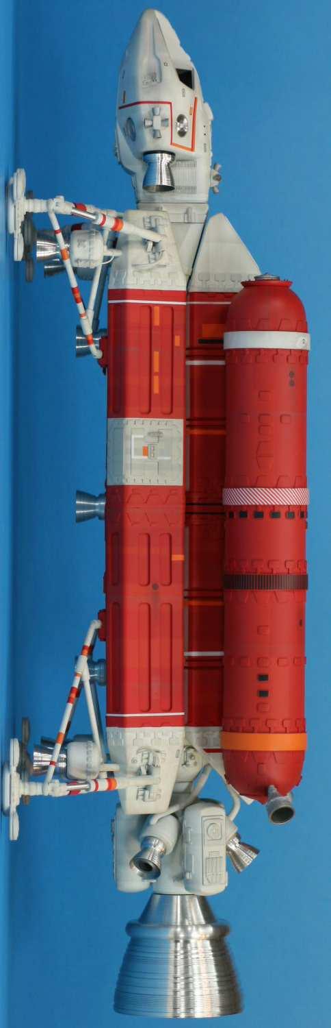
23 Sample kit (use as references for assembly) Version 10/12/2010 Page 23
24 Version 10/12/2010 Page 24

25 Version 10/12/2010 Page 25

26 Version 10/12/2010 Page 26
Blakes 7 DSV-1 Liberator
 Blakes 7 DSV-1 Liberator Model kit by Masterpiece Models: www.masterpiecemodels.com Pattern Maker: Alfred Wong Casting: J&S Technologies LLC Parts List Main body 3 Main body nose vanes 4 Main body detail
PS 5077 cu. ft. Boxcar with EOC device. 1:29 scale resin craftsman kit. by Burl Rice
 PS 5077 cu. ft. Boxcar with EOC device 1:29 scale resin craftsman kit by Burl Rice www.burlrice.com Bill of materials (not included): Thick/medium viscosity CA PL adhesive, or Gorilla Glue Heavy Duty Construction
Peter Krause ABN
 Peter Krause ABN 25 736 637 163 T/as O-Aust Kits PO Box 743 ALBANY CREEK QLD 4035 AUSTRALIA Phone +61 (0)7 3298 6283 (7.00pm to 9.30pm ONLY) Facsimile +61 (0)7 3298 6287 (24 hours) Mobile 0419 680 584
CONCEPT MODELS INSTRUCTIONS FOR UP DC-10 WING CAR El Toro Way Stockton, CA Web Address:
 CONCEPT MODELS Web Address: http://www.con-sys.com 8810 El Toro Way Stockton, CA 95210 INSTRUCTIONS FOR UP DC-10 WING CAR 2 CONCEPT MODELS PARTS DC-10 WING CAR Item No. Part No. DESCRIPTION QTY. 1 2003-1
Ziroli D-17 Beech Staggerwing
 Ziroli D-17 Beech Staggerwing Parts List Vacuform Parts: Miscellanous Pieces 1 Four Side Panels 1 3/16" Tube, 2" Long 2 Lower Dash - Back Dash 2 Felt, 12x24 3 Dash 3 Cordury 12x24 4 Dash Hood 4 Aluminum
Max Launch Abort System Prod. No *Kevlar is a registered trademark of Dupont
 Flying Model Parts List Max Launch Abort System Prod. No. 3014 A 11820 - Body Tube 3.5 Diam x 5.5" Long B 11824 - Orange Capsule Base Shoulder Ring C 16032 - Laser-cut Ring motor mount rear D 16033 - Laser-cut
SE5a Instrument Board part 2 - rev 1.1
 SE5a Instrument Board part 2 - rev 1.1 Fuel (Petrol) Valve This valve uses two circular name plates, eight brass screws, one black plastic base, copper wire and two black plastic risers. You can pick any
Hobby Lobby Zip Supplementary instructions Please refer to the included drawings while using these assembly instructions
 Materials needed: 15 or 30 minute epoxy Medium CA Masking tape Scotch tape Servo Tape Wax paper Tools Needed: Pencil or marker Flat building surface Hobby knife or razor blade 7/64" or 3mm drill bit 3/16"
Additional Parts List:
 THE TIME MACHINE Additional Parts List: In addition to the cast resin parts enclosed in this kit, there should also be a plastic bag containing the following items needed to complete your time machine
Continue gluing the remaining top parts ensuring the angled piece is glued well. Set aside and let dry. See photo below
 Radiator rev 1.1 The SE5a s radiator is one of the most recognized radiators in WW1. It is one of the components that defines the SE5a. The original SE5a has seen multiple radiator designs used during
CONCEPT MODELS INSTRUCTIONS FOR THE KASGRO KRL SPECIAL DEPRESSED CENTER FLAT CARS El Toro Way Stockton, CA 95210
 CONCEPT MODELS Web Address: http://www.con-sys.com Email: concept_models@con-sys.com 8810 El Toro Way Stockton, CA 95210 INSTRUCTIONS FOR THE KASGRO KRL 204000-2 SPECIAL DEPRESSED CENTER FLAT CARS 2 CONCEPT
Instructions for Lighting an S Scale Caboose
 Instructions for Lighting an S Scale Caboose The S Scale Caboose lighting kit is adaptable for most caboose models of rolling stock including American Flyer (TM) and contains the same components as found
HARRISON S HARDWARE PF5891
 1:48 BUILDING KIT HARRISON S HARDWARE PF5891 Model the local hardware store where layout residents can find all they need to keep their homes in tip-top shape and workshops running smooth. The positive
3Insert the second rod no. 4
 Yamato: Step-by-step 37 The stern block and searchlight control towers a b c d e f Recommended tools and materials Wood glue Sandpaper (no. 800 grain) Metal file Putty Craft knife For metal: Super Glue
1/6 PA-25 PAWNEE. *Specifications are subject to change without notice.*
 1/6 PA-25 PAWNEE INSTRUCTION MANUAL [ A335 Kit ] Wing Span : 72 in / 1830 mm Wing Area : 736 sq in / 47.5 sq dm Flying Weight : 6.6 lbs / 3000 g Fuselage Length : 48 in / 1220 mm Requires : "Glow Power"
Working with Resin Models
 Working with Resin Models This article will run through the basic techniques and methods required to get the most out of preparing, cleaning up and assembling Forge World s resin kits. If you need extra
1Take the keel (3) and
 and") 1 The hull and the bridge 1Take the keel (3) and apply PVA wood glue in the second slot from the left: a toothpick may make it easier. Take care: the left end is the one that has a projection. THE HULL
1 The hull and the bridge 1Take the keel (3) and apply PVA wood glue in the second slot from the left: a toothpick may make it easier. Take care: the left end is the one that has a projection. THE HULL
PITTS S2S CONSTRUCTION
 PITTS S2S CONSTRUCTION FUSELAGE CONSTRUCTION 1) Place the right fuselage side over the plan and mark the former positions. Place the left side over the right side and mark the former positions. Glue F1
Citabria Pro. Aerobatic Parkflyer. by Joel Dirnberger
 Citabria Pro Aerobatic Parkflyer by Joel Dirnberger Revision C: December 21, 2004 Citabria Pro Building Instructions Length: Wingspan: Wing Area: Flying Weight: Wing Loading: Functions: Specifications:
Big Oz. Rocket. User Guide V0313
 Big Oz Rocket User Guide 59824 V0313 Materials Included The Big Oz Rocket Kit should include the following materials. If something is missing, contact Customer Service at 800-358-4983. 20-ounce plastic
SCHWERE PLATTFORMWAGON TYPE SSY 60TON
 TWS 5094 SCHWERE PLATTFORMWAGON TYPE SSY 60TON Congratulations on purchasing one of the finer aftermarket resin kits sets available. The photo below is of the completed kit. The Panther tank is not included
1Use the metal file to smooth
 Yamato: Step-by-step 85 Parts of the bridge and the hull a b c d e f a Part of the bridge b Part of the bridge c Part of the bridge d Radar x 2 e Part of the bridge x 2 f Wire Recommended tools and materials
(Build Instructions)
") (Build Instructions) Specifications * Wingspan: 58cm * Length: 50cm * Flying Weight: 59 grams * Channels: 3 (Rudder Elevator Throttle) * Suggested Receiver: 4Ch Micro * Motor: 8mm GearDrive * Prop: GWS
(Build Instructions) Specifications * Wingspan: 58cm * Length: 50cm * Flying Weight: 59 grams * Channels: 3 (Rudder Elevator Throttle) * Suggested Receiver: 4Ch Micro * Motor: 8mm GearDrive * Prop: GWS
Tools and Tips: ( 1 )
") Tools and Tips: As you build instructions will show in my many picture manual how to assemble. You can use your own methods as you desire, my results are very good. A smooth, flat work surface is very
Tools and Tips: As you build instructions will show in my many picture manual how to assemble. You can use your own methods as you desire, my results are very good. A smooth, flat work surface is very
CONCEPT MODELS SP DOUBLE STACK CONTAINER CARS INSTRUCTIONS Sheep Ranch Rd. Mountain Ranch, CA Web Address:
 CONCEPT MODELS Web Address: http://www.con-sys.com 8331 Sheep Ranch Rd. Mountain Ranch, CA 95246 SP DOUBLE STACK CONTAINER CARS INSTRUCTIONS 2 CONCEPT MODELS PARTS Item No. PART NO. DESCRIPTION QTY. 1
Rural Shamrock Gas Station & Store kit in HO scale
 Rural Shamrock Gas Station & Store kit in HO scale Parking lot base and cars not included This kit includes all building parts and signs milled in white and black styrene plastic, clear window glazing
Shell Gas Station & Convenience Store kit in HO scale
 Shell Gas Station & Convenience Store kit in HO scale Parking lot base and cars not included This kit includes all building parts and signs milled in white and black styrene plastic, clear window glazing,
Tools and Tips: ( 1 )
") Tools and Tips: As you build instructions will show in my many picture manual how to assemble. You can use your own methods as you desire, my results are very good. A smooth, flat work surface is very
Tools and Tips: As you build instructions will show in my many picture manual how to assemble. You can use your own methods as you desire, my results are very good. A smooth, flat work surface is very
CONCEPT MODELS UTLX 80006,80020 CRYOGENIC TANK CAR KIT INSTRUCTIONS Sheep Ranch Rd. Mountain Ranch, CA 95246
 CONCEPT MODELS Web Address: http://www.con-sys.com Email: concept_models@con-sys.com 8331 Sheep Ranch Rd. Mountain Ranch, CA 95246 UTLX 80006,80020 CRYOGENIC TANK CAR KIT INSTRUCTIONS 2 CONCEPT MODELS
Rosalina Accessories Tutorial Version March 2011 Martyn
 Rosalina Accessories Tutorial Version 1.0 - March 2011 Martyn Star Brooch Feel free to experiment with these dimensions, you should make a template you are happy with, the method still works. 1) Creating
DAVENPORT DEPARTMENT STORE PF5214
 1:160 BUILDING KIT DAVENPORT DEPARTMENT STORE PF5214 Dress up your downtown scene with the classic Victorian architecture and large first-floor picture windows of the Davenport Department Store. Details
the wire, less is better. And make sure the bends on each truss wire are in line with the other. See the next photo.
 The following information and photographs are what I did to build the kit. Your methods and needs may differ from this which is fine. There is no right or wrong way if you are used to scratch building.
O-Aust Kits. QR Class CLF Louvred Wagon Kitset in O Scale 1:48
 O-Aust Kits PO Box 743 ALBANY CREEK QLD 4035 AUSTRALIA Phone +61 (0)7 3298 6283 (7.00pm to 9.30pm ONLY) Facsimile +61 (0)7 3298 6287 (24 hours) Mobile 0419 680 584 Email pa_rl_krause@bigpond.com Web www.oaustkits.com.au
ADVANCED ROCKETRY. Page 01. What you will need to build the Quest MEAN GREEN. Parts and exploded view of the Quest MEAN GREEN. Prod No.
 ADANCED Prod No. 5013 * What you will need to build the Quest MEAN GREEN Hobby Knife * Pencil Straight Edge Aliphatic Resin Wood Sanding Sealer & Brush Spray Paint Parts and exploded view of the Quest
Step by Step Wing Bagging
 Step by Step Wing Bagging By Evan Shaw 073 589 9339 evanevshaw@gmail.com Preparing the Leading Edge 1. Cut cores. (Cutting of wing cores is covered in another article elsewhere) 2. Sand the LE to a nice
FUSELAGE CONSTRUCTION
 FUSELAGE CONSTRUCTION Note: prior to building and gluing on the work surface use protective covering on your building surface. (wax paper or clear wrap) Fit the laser cut Fuselage Front and Fuselage Rear
J.W. cobbler 1:160 BUILDING KIT PF5210 WOODLAND SCENICS
 1:160 BUILDING KIT J.W. cobbler PF5210 The partially assembled walls, positive alignment system and prefinished edges make kit assembly quick, easy and accurate. This three-story brownstone features stacked
Cardboard Model Buildings
 Cardboard Model Buildings Get more model kits from http://www.modelbuildings.org PRINTING & ASSEMBLY TIPS: These OO designs can easily be resized by reducing the print percentage as follows: OO scale is
HRMLaserModels.com T.W. SNOW 25 TON COALING TOWER S SCALE AS USED ON THE MILWAUKEE ROAD
 HRMLaserModels.com T.W. SNOW 25 TON COALING TOWER S SCALE AS USED ON THE MILWAUKEE ROAD HRM-61 S SCALE COAL TOWER T.W.Snow 25 Ton Coaling Tower General Instructions Check out HRMLaserModels.com for construction
FLITZEBOGEN-2 Assembly instructions
 FLITZEBOGEN-2 Assembly instructions Trim the end of the fuselage to the length of 925mm from the nose. Be careful to avoid splitting the carbon fibers. Sand the base of the stab mount in preparation for
CONCEPT MODELS INSTRUCTIONS FOR PRODUCT 60,000 GALLON TANK CAR El Toro Way Stockton, CA 95210
 CONCEPT MODELS Web Address: http://www.con-sys.com Email: concept_models@con-sys.com 8810 El Toro Way Stockton, CA 95210 INSTRUCTIONS FOR PRODUCT 60,000 GALLON TANK CAR 2 CONCEPT MODELS PARTS GATX/UTLX
FireFighter.21 Building Instructions
 A Tom Moorehouse design. Thank-you for purchasing the FireFighter.21. I believe that you will find it to be the best.21 rigger kit available. It has won 1 st place in the 2006 AMPBA nationals! It was designed
Drawings of all parts have been included for ease of part identification.
 Acme Corporation Instructions for Assembly of the HO Scale Acme Corporation HO Kit Contents: 156 ea. white 1/16" laser cut acrylic part 10 ea. white 1/8" laser cut acrylic part 37 ea. adhesive-backed brick
Pre-Paint>Wings>Fit ailerons. Objectives of this task: Materials and equipment required: Size the ailerons and pre-mould strips
 Pre-Paint>Wings>Fit ailerons Objectives of this task: In this task the ailerons and the pre-mould strips will be sized and trimmed, then flocked onto the wings and glassed in place, and the next day the
CA to each one. You may have to hold the end down while to glue sets or use an accelerator like I did.
 The following information and photographs are what I did to build the kit. Your methods and needs may differ from this which is fine. There is no right or wrong way if you are used to scratch building.
How to make a template to mount your plaque to a surface
 How to make a template to mount your plaque to a surface A piece of heavy paper 3 4 wider than your plaque on all four sides (paper grocery bag works great too) Small amount of paint (latex dries the fastest)
Ben Franklin 5&10 Store
 Ben Franklin 5&10 Store RIVER LEAF MODELS, LLC RIVER LEAF MODELS, LLC Thank you for purchasing the Ben Franklin 5&10 structure kit. Your kit includes everything you need to assemble the final product.
NSWGR Class SRC Refrigerated Wagon Kitset in 7mm Scale
 O-Aust Kits PO Box 743 ALBANY CREEK QLD 4035 AUSTRALIA Phone +61 (0)7 3298 6283 (7.00pm to 9.30pm ONLY) Facsimile +61 (0)7 3298 6287 (24 hours) Mobile 0419 680 584 Email pa_rl_krause@bigpond.com Web www.oaustkits.com.au
Thank you for purchasing E.L. Moore Window & Door.
 Thank you for purchasing E.L. Moore Window & Door. Instructions Version 4.28.15 I ve named this kit after one of the greatest modelers I ve ever known, the late Elliot Moore Jr. Rest in peace my friend.
FRAMED PANEL / DOOR / PANEL CONTINUOUS HINGE SHOWER ENCLOSURE INSTALLATION INSTRUCTIONS
 FRAMED / DOOR / CONTINUOUS HINGE SHOWER ENCLOSURE INSTALLATION INSTRUCTIONS QCI5229 Rev 0 6 INSTALLATION NOTES: Unpack your unit carefully and inspect for freight damage. Lay out and identify all parts
Aerospace Speciality Products
 Specifications:! Length: 18.75"/47.6 cm! Diameter: 0.98"/24.9 mm! Weight: 1.5 oz/44 gm! Streamer Recovery! Recommended Engines:!! A8-3; B4-4; B6-4; C6-5! Skill Level: Beginner This is a model rocket kit
Assembly Instructions
 Assembly Instructions Parts Included: 1 Nose Cone 1 Body Tube 3 1/8 Balsa Fins 1 Thrust Ring 1 Motor Tube 1 Motor Hook 1 Motor Sleeve 2 Centering Rings 1 Launch Lug 1 Kevlar Shock Cord (yellow) 1 Elastic
WRIGHT FLYER 1 INSTRUCTIONS FOR THE D10LC KIT
 WRIGHT FLYER 1 INSTRUCTIONS FOR THE D10LC KIT Manufactured in the USA by Easy Built Models PO Box 681744, Prattville, AL 36068-1744 Visit us at www.easybuiltmodels.com Easy Built Models GLUE METHODS Always
Instructions for Assembly of the HO Scale The Charles
 The Charles Instructions for Assembly of the HO Scale The Charles HO Kit Contents: 337 ea. white 1/16" laser cut acrylic part 19 ea. Clear 1/16" laser cut acrylic part 69 ea. white 1/8" laser cut acrylic
675 Quick N Stall Neo Angle Framed Hinge Shower Enclosure
 INSTALLATION INSTRUCTIONS 675 Quick N Stall Neo Angle Framed Hinge Shower Enclosure Call Technical Dept @ 1-800-452-2726 QCI1003 Page 1 of 9 Certified 10/01/09 INSTALLATION NOTES: Unpack your unit carefully
INSTALLATION INSTRUCTIONS. Deluxe Continuous Hinge Inline Door & Panel Shower Enclosure QCI5230
 INSTALLATION INSTRUCTIONS Deluxe Continuous Hinge Inline Door & Panel Shower Enclosure QCI5230 QCI5230 Rev 0 6 shower new QCI5230 Rev 0 Page 2 Certified 06/20/2016 Parts List A. Curb (w/ weep holes) (1)
Model the hub of your layout s rural setting. Planters Feed and Seed Supply Instructions N Scale 1:160 WOODLAND SCENICS
 PF5201 Planters Feed and Seed Supply Instructions N Scale 1:10 Model the hub of your layout s rural setting. Planters Feed and Seed Supply presents a vintage agricultural center where farmers and rural
50 FineScale Modeler January Finding (Captain) Nemo
 Nemo") 50 FineScale Modeler January 2005 Finding (Captain) Nemo 1/70 Scale Sci-Fi How-to In 1954, Walt Disney Pictures launched its big-screen adaptation of Jules Verne s classic adventure novel, 20,000 Leagues
50 FineScale Modeler January 2005 Finding (Captain) Nemo 1/70 Scale Sci-Fi How-to In 1954, Walt Disney Pictures launched its big-screen adaptation of Jules Verne s classic adventure novel, 20,000 Leagues
CORNER PORCH HOUSE PF5196
 1:87 BUILDING KIT CORNER PORCH HOUSE PF5196 Two-story home with cedar-shake roof and a corner wrap-around porch. Clapboard siding, paned windows, and loaded with accessories, such as a bicycle built for
The Rubley Building Instructions for Assembly of the N scale kit. v1.1
 The Rubley Building Instructions for Assembly of the N scale kit. v1.1 Kit Contents: 197 ea. laser cut 1/16" acrylic parts. 1ea. adhesive backed.020 styrene part. 10 ea..060 x 1" styrene alignment pins.
Hubble Space Telescope Paper Model Directions Downloads, patterns, and other information at:
 Hubble Space Telescope Paper Model Directions Downloads, patterns, and other information at: www.hubblesite.org/go/model Materials: model pattern printed onto cardstock/coverstock instructions printed
BRF-022 YGH SEALION. Building Instructions
 Tel 07747 018544 www.prmrp.com BRF-022 YGH SEALION Building Instructions SCALE MODEL PRODUCT FOR ADULT MODELLERS ONLY. WHITE METAL CONTAINS LEAD WASH HANDS AFTER USE. MAY CONTAIN SMALL PARTS. ETCHED BRASS
Modular Locomotive System Instruction Manual for HBK22 Fowler Body Kit
 Modular Locomotive System Instruction Manual for HBK22 Fowler Body Kit Roundhouse Engineering Co. Ltd. Units 6-10 Churchill Business Park. Churchill Road, Wheatley. Doncaster. DN1 2TF. England. Tel. 01302
Season One Phaser Kit PRP1745
 Season One Phaser Kit PRP1745 RODDENBERRY ENTERTAINMENT STAR TREK: THE NEXT GENERATION SEASON ONE PHASER KIT Thank you for your purchase of the Roddenberry Entertainment Star Trek: The Next Generation
Model Grandma and Grandpa s cozy cottage, a. Country Cottage Instructions HO Scale 1:87 WOODLAND SCENICS PF5186
 PF586 Country Cottage Instructions HO Scale :87 Model Grandma and Grandpa s cozy cottage, a young family s first home or give this vintage Victorian cottage the run-down look of an abandoned shack. This
Bates 1/8 scale B-26. Parts List. Instructions
 Bates 1/8 scale B-26 Vacuform Pieces Swivel Ball 1 Cockpit Floor 1 Ball 2 Cockpit Back Wall 2 Two Flanges 3 Dash 3 Seven 0-64 x 1/4 Bolts 4 Dash Hood 4 Seven 0-64 Nuts 5 Center Console 6 Pilot Seat Fire
LANDING GEAR. 1. Fit landing gear into slots on bottom of fuselage.
 LANDING GEAR 1. Fit landing gear into slots on bottom of fuselage. 4. Use channel-lock pliers to press blind nuts into position (note: drilled hole should be slightly smaller than shaft of blind nut for
3Position the hull of the ship as
 Yamato: Step-by-step 25 The hull and stern deck c b d a b d c e e f a Rear frame b Stern deck x 2 c Stern deck x 2 d Side wall x 2 Wood glue Sandpaper (no. 400 grain) Craft knife Pliers d Side wall x 2
Background: For the Modeler:
 Right On Replicas, LLC Step-by-Step Review 20141020* Space Shuttle with Fuel Tank and Boosters 1:72 Scale Monogram Model Kit #85-5089 Review (Part 1 of 2) Background: The United States Space Transportation
Nanton Grain Mill Assembly
 ( 1 ) Nanton Grain Mill Assembly Locate package for assembling storage building. These are cut from 1/8 masonite. Inspect and lightly sand edges where it will be bonded. Use white glue or CA glue to bond.
Tool Wagon Assembly Instructions
 Tool Wagon Assembly Instructions Adhesives Wood to wood joints are best done with a PVA wood glue but a good quality, slow acting (beware of instant grab ) cyanoacrylate super glue can be used if preferred.
EXTRA 330SC 60CC. Item No:H G Specifications cc gas DA50,DA60, DLE55, DLE60(twin), 3W55. Description
, 3W55. Description") EXTRA 330SC 60CC Item No:H G060011 Specifications Wing Span Length Wing Area Flying Weight Gasoline Radio Description Carbon Fibre : 92" (2347mm) 84 1/2 " (2060mm) 1526.8 sq in(98.5sq dm) 16 17lbs(7300
EXTRA 330SC 60CC Item No:H G060011 Specifications Wing Span Length Wing Area Flying Weight Gasoline Radio Description Carbon Fibre : 92" (2347mm) 84 1/2 " (2060mm) 1526.8 sq in(98.5sq dm) 16 17lbs(7300
Fokker Dr1 Master Instructions
 Fokker Dr1 Master Instructions Rev 1 Congratulations on your new project. This Dr1 kit is the finest to date. The construction of the plane is similar and exactly like the original. Take your time and
C-57D Starcruiser Paint Scheme
 Introduction The interior set of the C-57D appears to have been painted in neutral gray tones. Some interior colors were produced by side lighting with colored filters. These paints were chosen to recapture
Central New York Rocket Team Challenge 2018 Rocket Assembly Instructions
 Central New York Rocket Team Challenge 2018 Rocket Assembly Instructions Note: These instructions vary from those provided by the manufacturer of the rocket kits. There is also considerable varying discussion
Pre-Paint>Fuselage>Empennage>Fit elevator. Objectives of this task: Materials required: Prepare the horizontal stabiliser and the elevator
 Pre-Paint>Fuselage>Empennage>Fit elevator Objectives of this task: To fit the elevator to the horizontal stabiliser, to fit the trim tabs to the elevator and the end caps to the elevator and the horizontal
PRO CYCTM PRO CYC, INC. SYSTEM 1.5 FS
 ASSEMBLY INSTRUCTIONS Congratulations on your decision to use the world s most advanced and user-friendly cyclorama system. We have taken a great deal of care to create and ship your cyc, so please take
Cowper From Steve Wolverton on the T&TTT forum, Feb 2005 For Reference Only Do not use to build a trailer. Check on Teardrop and Tiny Travel Trailers
 Cowper From Steve Wolverton on the T&TTT forum, Feb 2005 For Reference Only Do not use to build a trailer. Check on Teardrop and Tiny Travel Trailers for up to date building information; http://www.mikenchell.com/forums
Palladian/ Keystone Models 202/204 Maintenance Kit
 Palladian/ Keystone Models 202/204 Maintenance Kit Please read all of the instructions before you begin. Confirm that you have all the necessary tools and parts required. Allow about one hour to complete
U-bass Kit Assembly Instructions
 U-bass Kit Assembly Instructions Compiled by playubass.com This guide is built from the instructions found here: http://kalabrand.com/ubass-kit/index.html Tools Needed 5/8 (16 mm) Wrench 7/16 (~11 mm)
TRUE TECHNICAL SERVICE MANUAL - ALL MODELS. DOORS/DRAWERS/LIDS
 DOORS/DRAWERS/LIDS 55 56 NOTES DOORS/DRAWERS/LIDS Swing s 73 74 NOTES INSTALLATION OF A GDM-SWING DOOR Phillips Head Screwdriver (2) - 1/8" Drift Punches (forged) Top Bracket NOTE: It may be necessary
MECOA EZ-4061 Trainer
 MECOA EZ-4061 Trainer EZ-4061 is a newly designed, Almost Ready to Fly kit. It is an extremely easy to control trainer with strong construction and excellent aerodynamic performance. This is a great choice
The Park Hotel Instructions for Assembly of N Scale Kit
 The Park Hotel Instructions for Assembly of N Scale Kit Kit Contents: 198 ea. Laser Cut Acrylic Parts, 2 ea. Chimney Parts Sheets, 1 ea.2".040 styrene rod, 5 ea. Sidewalk Parts, 14 ea. Cast Resin Dormers,
Right On Replicas, LLC Step-by-Step Review * Willys MB Jeep 1:35 Scale Tamiya Model Kit #35219 Review
 Right On Replicas, LLC Step-by-Step Review 20150211* Willys MB Jeep 1:35 Scale Tamiya Model Kit #35219 Review The Jeep was designed in a crash program in 1941 to be used throughout World War II. The iconic
Sentinel Armor Kit Assembly Guide
 1 Sentinel Armor Kit Assembly Guide 2 Thank you for purchasing the Mynock s Den Collection Sentinel Armor Kit by Vader s Vault. This guide will help you assemble your new kit, so be sure to keep it close
Obtained from Omarshauntedtrail.com
 DaveintheGrave's Halloween Props Animated Crawling Skeleton Build a life-size skeleton torso that realistically crawls across the lawn one arm at a time. 1. Motor Base and Linkage Assembly BASE - I used
PRO 400 M401 MFP M425 CF-280A/X TONER CARTRIDGE REMANUFACTURING INSTRUCTIONS
 HP PRO 400 M401 MFP M425 CF-280A/X TONER CARTRIDGE REMANUFACTURING INSTRUCTIONS HP CF-280A/X TONER CARTRIDGE REMANUFACTURING THE HP LASERJET PRO 400 M401/MFP M425 (CF-280A/X) TONER CARTRIDGE By Mike Josiah
C-180 Builder s Manual
 C-180 Builder s Manual. May 20, 2002 Last revised July 11, 2002 Copyright! 2002 Douglas Binder, Mountain Models www.mountainmodels.com sales@mountainmodels.com (719) 630-3186 1 Required Equipment! Xacto
Assembly Instructions for Summit Motel Kits # SMFS and SMBD
 Assembly Instructions for Summit Motel Kits # SMFS and SMBD Introduction Thank you for your purchase of the Summit Motel. This modern motel can be converted to almost any chain motel of your choice, depending
Building Instructions Diva cabin boat
 Building Instructions Diva cabin boat Order no. 3093/00 aero-naut Modellbau Stuttgarterstr. 18-22 D-72766 Reutlingen / Germany http://www.aero-naut.com 1 For pictured building instructions please see the
Captain Baxter, 3D Print instructions
 Captain Baxter, 3D Print instructions Baxter prototype printed by Shapeways and a home 3D printer Thank you for purchasing the Captain Baxter 3D print, this will instruct you on how to put this model together,
Aliphatic Resin Wood Glue. Launch Lug. Part #10009 Kevlar* Cord. Part #J0053
 ADANCED Prod No. 5014 * What you will need to build the Quest Lil GRUNT Hobby Knife * Pencil Straight Edge Aliphatic Resin Wood Sanding Sealer & Brush Spray Paint Parts and exploded view of the Quest Lil
INSTALLATION INSTRUCTIONS FRAMELESS CONTINUOUS HINGE SHOWER ENCLOSURE QCI5232
 INSTALLATION INSTRUCTIONS FRAMELESS CONTINUOUS HINGE SHOWER ENCLOSURE QCI5232 QCI5232 Rev 0 Page 1 Certified 06/20/2016 INSTALLATION NOTES: Unpack your unit carefully and inspect for freight damage. Lay
Scratchbuild A Backwoods Water Tank Part V - Making the Frost Box and Hanging the Water Spout
 Scratchbuild A Backwoods Water Tank Part V - Making the Frost Box and Hanging the Water Spout By Dwight Ennis In this section, we're going to make the Frost Box, and we'll build the Spout Hanger Assembly
How to operate (folding)
") How to operate (folding) LEFT HAND STACKING OUTWARD OPENING How to operate (folding) RIGHT HAND STACKING OUTWARD OPENING LOCK BOTH LEVER HANDLE AND FLAT HANDLE UTILISING THE D-HANDLE LOCATED ABOVE THE
How to operate (folding) LEFT HAND STACKING OUTWARD OPENING How to operate (folding) RIGHT HAND STACKING OUTWARD OPENING LOCK BOTH LEVER HANDLE AND FLAT HANDLE UTILISING THE D-HANDLE LOCATED ABOVE THE
1Smooth pieces 4, 5 and 6, using
 Yamato: Step-by-step 109 Machine-guns, anti-aircraft guns and decking h e f a b c g d e f a Anti-aircraft gun base x 2 b Anti-aircraft gun (bottom) x 2 c Anti-aircraft gun (top) x 2 d Machine-gun base
Billy Body Kit HBK5 CHECKLIST. Modular Locomotive System Instruction Manual for HBK5 Billy Body Kit. Checked
 Billy Body Kit HBK5 CHECKLIST 1 Cab body panel (folded). 1 Cab floor. 1 Cab front panel. 1 Roof. 1 Body tank support. 2 Boiler bands with M2 Long Steel Screws & Nuts fitted. 1 Brass dome. 1 Cast brass
Side and rear window, assembly overview
 64-7 Side and rear window, assembly overview 1 - Side/rear window Removing Unbroken Page 64-9 Broken Page 64-11 Installing Page 64-13 Curing time Page 64-21 Re-sealing Page 64-25 2 - PUR adhesive sealant
VICTORIAN RAILWAYS QR BOGIE OPEN WAGON
 C/- P.O. Rhyll, Victoria, 3923. VICTORIAN RAILWAYS QR BOGIE OPEN WAGON Prototype Notes QR number 1 was built at the VR Newport workshops in 1889, being the forerunner of a long lived and useful class of
Hardee s Restaurant kit in HO scale
 Hardee s Restaurant kit in HO scale Parking lot base and cars not included This kit includes all building parts milled in white styrene plastic and laser cut white acrylic, clear acrylic window glazing,