The Rubley Building Instructions for Assembly of the N scale kit. v1.1
|
|
|
- Clarissa Farmer
- 6 years ago
- Views:
Transcription
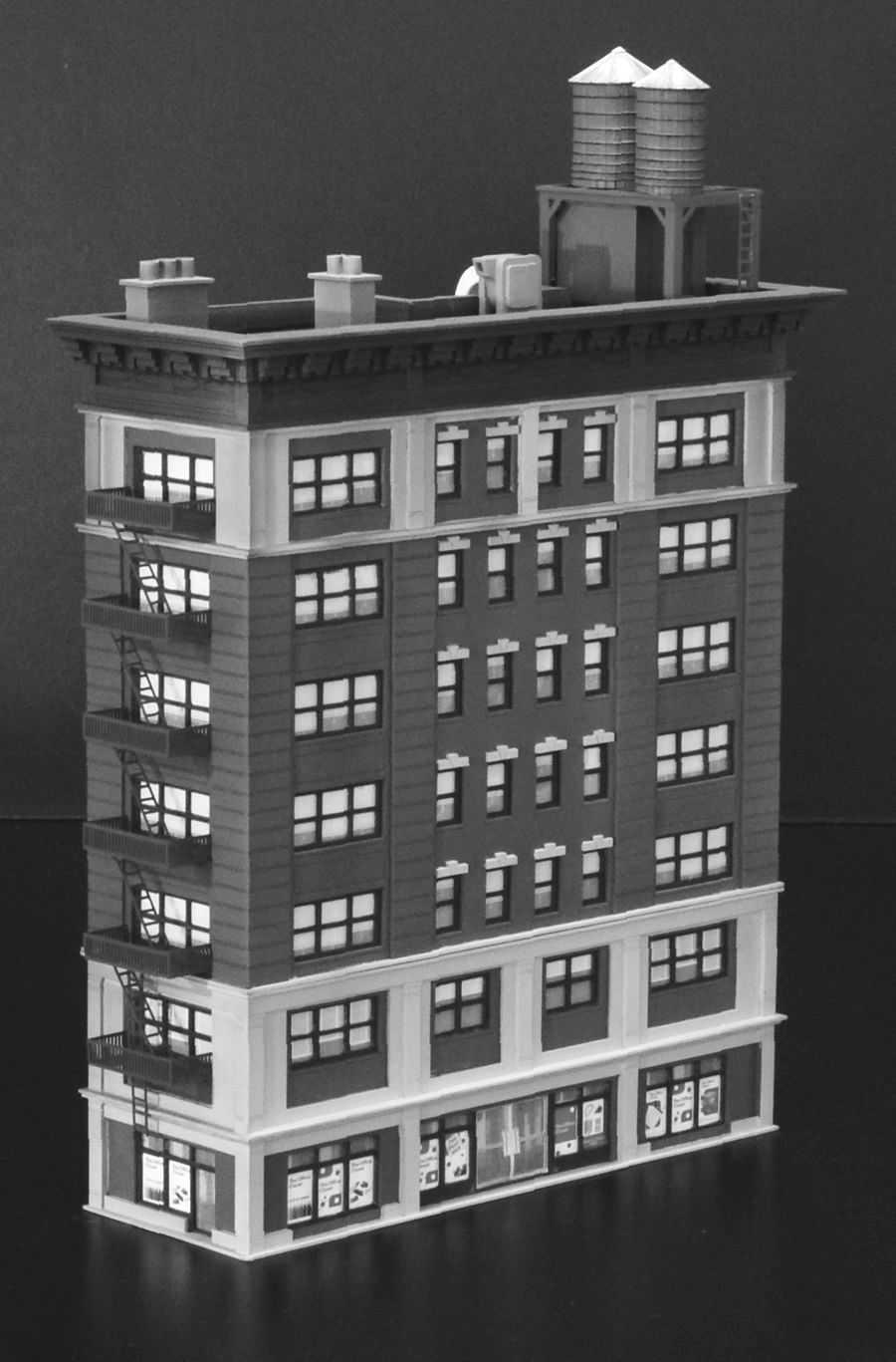
1 The Rubley Building Instructions for Assembly of the N scale kit. v1.1 Kit Contents: 197 ea. laser cut 1/16" acrylic parts. 1ea. adhesive backed.020 styrene part. 10 ea..060 x 1" styrene alignment pins. 1 ea..125" x 3" styrene tube 2 ea. cast water tanks 6 ea..020 fire escape parts sheet 5 ea. sidewalk parts 2 ea. window glass templates 2 ea. window glazing Instructions with diagrams Thank you for purchasing this kit. Please read these instructions completely before beginning and take your time. Allow parts to dry after painting or gluing and do not try to build this in one night. Drawings of all the parts have been included for ease of part identification. Practice gluing the acrylic together if you have never done it before. There is plenty of scrap in your kit that you can use for this. If by chance a part is missing or broken, please write us indicating the kit name and part number and we will send you a replacement. Please note that parts of the kit have been painted gray in the assembly photos so that new parts can easily be seen and identified. This is only for ease of identifying parts and seeing them clearly in the photos. We recommend gluing all parts together prior to painting unless otherwise noted. Pre-production models were used in these instructions, your parts may vary slightly. You will need the following items to assemble your model: Sharp hobby knife, file, paint (see Painting Your Model ), paint brushes, glue (see Gluing Acrylic ), modeling putty. About the Kit The building is based on a New York mid-rise retail/commercial/apartment building located in SOHO. It includes graphics for several retail vendors on the first level. Our model has seven floors as well as roof details and water towers. 1
2 The assembly of each unit is very similar. Once you have built the first unit you will most likely be able to build the rest without reading the instructions. However... I spent a lot of time writing the instructions so I would appreciate it if you would. Repetitive sequences will be described in detail the first time and then less so subsequently. Parts are labeled in the instructions inside parentheses. The first number is the unit number and the second is the part number in that unit. For instance (3-6) would be part six in unit three. Each unit has a base and top that are identified with a letter. As these are the same for multiple units there is no unit number associated with these. The engraved letter should always be facing up during construction. Many parts have engraved details on them. Be sure that these are facing out when gluing the parts together. It is easy to install these backwards by mistake. Gluing Acrylic Always glue acrylic in a well-ventilated area, and read the glue manufacturer s label for instructions. We recommend using Tenax-7R by Hebco or Plastruct brand Plastic Weld Solvent Cement (PPC-2 or PPC-16) or Bondine Solvent Cement (Bond-2 or BOND-16). Tenax-7R comes with a dispenser and Plastruct sells a Solvent Syringe (HT-8 or HT-10) and various other solvent dispensers. Most hobby shops carry these products. Acrylic must be glued together using a solvent that will melt the two edges and literally fuse them together. To do this, place the two pieces to be joined together and run a bead of solvent down the edge. Capillary action will suck the solvent into the joint and after several seconds the pieces will be fused. After only a few minutes the pieces will be strong enough to work with. The bond will be completely dry within twenty-four hours using the above-mentioned products. Solvent can be dispensed two ways. Typically the solvent comes in a small bottle with a brush in the lid. The brush allows you to dispense a drop or two of solvent at a time. You may want to use a polyethylene bottle or syringe with a blunt needle dispenser. This allows larger amounts of solvent to be dispensed quickly and cleanly. Be sure the bottle you are using is approved for the solvent you are using or you may melt through it. These may be purchased from CMR. Cyanoacrylate (CA) Super Glue Parts that are not plastic or are painted prior to gluing must be glued together using a non solvent based glue. This means the parts are held together by the glue and not the process of fusing or welding them together with solvent. For this we recommend using CA where noted in the instructions. 2

3 Craft Glue Some parts are easier to glue using craft glue such as Sobo. We use craft glue to stick previously painted parts together when we want a little working time. We used craft glue for attaching the roof details to the building and for gluing the units together in the final assembly. Preparing Your Model for Painting We recommend lightly sanding all parts to remove the raised edge created during the laser cutting process. In order to hide the seams we recommend using hobbyist putty such as Green Squadron modeling putty. Do this in a very well-ventilated area. Apply the putty over the seams and allow to dry overnight. Once the putty has dried, place a sheet of fine sandpaper on a flat surface and sand smooth. You may need to apply a second coat of putty and sand again. You may choose to wrap the engraved lines around the corners with a small triangular jewelers file. See Figure 1. Figure 1 Note on Tabs Sometimes it is necessary to sand or file the tabs slightly in order to get them to seat themselves into the slots. This is due to slight variations in acrylic thickness. If the tabs are not fitting into the slots properly, you may need to file them back at an angle to fit properly. 3

4 Painting Your Model After building each unit we primed our building with Krylon Gray spray paint. We also primed the window frames. For our building paint scheme, we used acrylic hobby paints which are available in most hobby stores. We painted the building two tone cream and brown. We first painted the building brown with an airbrush and then painted the cream by hand. The roof unit was sprayed an Olive Drab color. The roof was painted black. We painted parts of the back of the building white by masking it and spraying it with flat white spray paint. This represents an area that was repaired and repainted. The building was then airbrushed with dirt and grime to give it an aged look. Finally we clear coated the building with matte spray to protect the paint finish. The window frames were painted Olive Drab. The roof details were hand painted various colors by hand and then applied to the finished building later. The fire escapes were sprayed with Krylon Ruddy Brown Primer. 4

5 Window Glass There are printed window shades included with your kit. These are designed to be laminated with acetate window glazing prior to installing in your model. The printed window shades are numbered to correspond with the window frame parts. Lightly spray glue the window shade pages on the printed side with spray mount and apply a sheet of acetate to them. Press in place. We used 3M Spray Mount part number 6065 which is available at craft and office supply stores. After painting the window frames glue them to the acetate using super glue (CA). Place the acetate with the window frames glued to it face up on a cutting mat and trim out the frames and any excess glazing with a hobby knife. See Figure 2. It is recommended to lightly spray the back of the window shade pages with a sealer such as matte spray or laquer. This will keep the paper from buckling due to humidity changes later. Figure 2 5
 into the slots on the front side of part (A) and glue in place. See Figure 3 for orientation.")
, (1-4), (1-5), (1-6) and (1-7) gluing into the slots on the back side of part (A) as shown in the figures. Make sure the doors are oriented properly.")
 onto the assembly with the engraved part number facing up. Check that all the tabs are seated properly. Remove (B) and set aside for later.")
6 Unit 1 Begin by taking base (A) and laying it flat on your work surface with the engraved part number facing up. Working clockwise, insert the tabs of the front wall (1-1) into the slots on the front side of part (A) and glue in place. See Figure 3 for orientation. Next, insert the tabs of the side wall (1-2) into the slots on the side of part (A) and glue in place. The two walls should meet and be glued at the corner. See Figure 4. Figure 3 Continue with the back walls (1-3), (1-4), (1-5), (1-6) and (1-7) gluing into the slots on the back side of part (A) as shown in the figures. Make sure the doors are oriented properly. See Figures 4 & 5. Insert the tabs of the alley wall (1-8) into the slots on the alley side of part (A) and glue in place to form a box. Make sure to glue all the corners together. See Figure 5. Figure 4 Test fit but DO NOT GLUE the top (B) onto the assembly with the engraved part number facing up. Check that all the tabs are seated properly. Remove (B) and set aside for later. Next glue wall (1-9) behind wall (1-1). The part should be centered on the wall. Glue wall (1-10) behind wall (1-2). The door opening should align perfectly on the two walls. Glue wall (1-11) behind wall (1-8). The door opening on (1-11) is slightly narrower and should be centered in the door opening on (1-8). See Figure 6. Figure 5 6 Figure 6
 and (13) will be used together to create the corners.")


7 There are two parts to each corner column that go on Unit 1, the columns parts labeled (12) are slightly wider than the columns parts labeled (13). There are also left and right and center columns parts so pay attention to where they go and their orientation. Parts (12) and (13) will be used together to create the corners. Column part (13) should be glued on first, flush with the front edge of the building. Then, column part (12) which will overlap the edge of part (13) to create a symmetrical corner column. Note that there are not columns on the back of the building. Glue the columns to the walls as shown in Figures 7 & 8. Figure 7 Glue the top (B) onto the assembly with the engraved part number facing up. Check that all the tabs are seated properly. Clean up any imperfections, fill any gaps with modelers putty and sand any rough edges. Wash the unit with soap and water and allow to dry. Paint Unit 1 as described earlier in the Painting Your Model section of these instructions. Figure 8 Paint the window frames (1-14) x 2, (1-15), (1-16), and doors (1-17), (1-18) x2 your choice of color and install the window glazing as described earlier in the Window Glass section of these instructions. Install the windows in Unit 1. See Figures 9 & 10. Paint the door (1-19) silver. Peel the backing off the part and adhere to the glass in the door opening. Figure 9 7 Figure 10
 into the slots on the front side of part (C) and glue in place. Note that the thicker side of (2-1) is the top of the part.")
 is the top of the part.")
 and (2-6) attach to (2-5), and the tabs are not symmetrical, to help with alignment.")
8 Unit 2 Lay part (C) flat on your work surface with the engraved part number facing up. Working clockwise, insert the tabs of the front wall (2-1) into the slots on the front side of part (C) and glue in place. Note that the thicker side of (2-1) is the top of the part. Next, insert the tabs of the side wall (2-2) into the slots on the side of part (C) and glue in place. The two walls should meet and be glued at the corner. Note that the thicker side of (2-2) is the top of the part. Figure 11 Continue with the back walls (2-3), (2-4), (2-5), (2-6) and (2-7) gluing into the slots on the back side of part (C) as shown in the figures. Make sure the engraved sills are facing out and the walls are oriented correctly. The narrow edge of parts (2-4) and (2-6) attach to (2-5), and the tabs are not symmetrical, to help with alignment. Insert the tabs of the alley wall (2-8) into the slots on the alley side of part (C) and glue in place to form a box. Make sure the orientation of the window opening is on the correct side. The tabs are not symmetrical, to help with alignment. Make sure to glue all the corners together. See Figure 11. Test fit but DO NOT GLUE part (D) onto the assembly with the engraved part number facing up. Check that all the tabs are seated properly. Remove (D) and set aside for later. Next glue wall (2-9) behind wall (2-1). The part should be centered on the wall. Glue wall (2-10) behind wall (2-2). Glue wall (2-11) behind wall (2-8). See Figure 12. Glue the column part (2-13) to the side of the unit. It should be flush on both ends. Glue the column part (2-14) to the alley side of the unit. It should be flush on both ends. Glue the column part (2-12) to the front of the unit; it should overlap the other two column parts. See Figures 12 & 13. Figure 12 8 Figure 13

 x3, (2-16), (2-17) x2, (2-18) x3 your choice of color and install the window glazing as described earlier in the Window")
9 Glue the top (D) onto the assembly with the engraved part number facing up. Check that all the tabs are seated properly. See Figure 14. Clean up any imperfections, fill any gaps with modelers putty and sand any rough edges. Wash the unit with soap and water and allow to dry. Paint Unit 2 as described earlier in the Painting Your Model section of these instructions. Figure 14 Paint the window frames (2-15) x3, (2-16), (2-17) x2, (2-18) x3 your choice of color and install the window glazing as described earlier in the Window Glass section of these instructions. Install the windows in Unit 2 as shown in the figures. See Figures 15 & 16. Figure 15 Figure 16 9
 into the slots on the front side of part (E) and glue in place. See Figure 17 for orientation.")
, (3-4), (3-5), (3-6) and (3-7) gluing into the slots on the back side of part (E) as shown in the figures.")
 into the slots on the alley side of part (E) and glue in place to form a box.")
10 Unit 3 Lay part (E) flat on your work surface with the engraved part number facing up. Working clockwise, insert the tabs of the front wall (3-1) into the slots on the front side of part (E) and glue in place. See Figure 17 for orientation. Next, insert the tabs of the side wall (3-2) into the slots on the side of part (E) and glue in place. The two walls should meet and be glued at the corner. See Figure 17. Continue with the back walls (3-3), (3-4), (3-5), (3-6) and (3-7) gluing into the slots on the back side of part (E) as shown in the figures. Make sure the engraved sills are facing out and the walls are oriented correctly. The narrow edge of parts (3-4) and (3-6) attach to (3-5), the tabs are not symmetrical to help with alignment. See Figure 17. Insert the tabs of the alley wall (3-8) into the slots on the alley side of part (E) and glue in place to form a box. Make sure the orientation of the window opening is on the correct side. The tabs are not symmetrical to help with alignment. Make sure to glue all the corners together. See Figure 17. Figure 17 Figure 18 Test fit but DO NOT GLUE part (F) onto the assembly with the engraved part number facing up. Check that all the tabs are seated properly. Remove (F) and set aside for later. There are two different parts to each corner column that go on Unit 3, the columns parts labeled (3-9) are slightly wider than the columns parts labeled (3-10). Parts (3-9) and (3-10) will be used together to create the corners. Glue column part Figure 19 (3-10) to side and alley walls flush with the front wall. Glue column parts (3-9) to the front wall overlapping column parts (3-10) to create a corner. Glue the remaining columns (3-9) to the building as shown in the figures. See Figures 18 &


11 Glue the top (F) onto the assembly with the engraved part number facing up. Check that all the tabs are seated properly. See Figures 18 & 19. Glue the lintels (3-11) x16 overtop of the windows. See Figures 18 & 19. Clean up any imperfections, fill any gaps with modelers putty and sand any rough edges. You may want to wrap some of the engraved lines around the corners with a small jewelers file. Wash the unit with soap and water and allow to dry. Paint Unit 3 as described earlier in the Painting Your Model section of these instructions. Paint the window frames (3-12), (3-13) x3, (3-14) x2, (3-15) your choice of color and install the window glazing as described earlier in the Window Glass section of these instructions. Install the windows in Unit 3 as shown in the figures. See Figures 20 & 21. Figure 20 Figure 21 11
 into the slots on the front side of part (G) and glue in place.")
 these should be facing out and be visible. They will be covered by the columns later.")
12 Unit 4 Lay part (G) flat on your work surface with the engraved part number facing up. Working clockwise, insert the tabs of the front wall (4-1) into the slots on the front side of part (G) and glue in place. Next, insert the tabs of the side wall (4-2) into the slots on the side of part (G) and glue in place. Note that there are two engraved F for front or Figure 22 face on part (4-2) these should be facing out and be visible. They will be covered by the columns later. The two walls should meet and be glued at the corner. Continue with the back walls (4-3), (4-4), (4-5), (4-6) and (4-7) gluing into the slots on the back side of part (G) as shown in the figures. Make sure the engraved sills are facing out and the walls are oriented correctly. The narrow edge of parts (4-4) and (4-6) attach to (4-5), the tabs are not symmetrical to help with alignment. Insert the tabs of the alley wall (4-8) into the slots on the alley side of part (G) and glue in place to form a box. Make sure the orientation of the window opening is on the correct side. The tabs are not symmetrical to help with alignment. Make sure to glue all the corners together. See Figure 22. Test fit but DO NOT GLUE part (H) onto the assembly with the engraved part number facing up. Check that all the tabs are seated properly. Remove (H) and set aside for later. Next glue wall (4-9) behind wall (4-1). The part should be centered on the wall. Glue wall (4-10) behind wall (4-2). Glue wall (4-11) behind wall (4-8). See Figure 23. There are two parts to each corner column that go on Unit 4, the columns parts labeled (12) are slightly wider than the columns parts labeled (13). There are also left and right and center columns parts so pay attention to where they go and their Figure 23 orientation. Parts (12) and (13) will be used together to create the corners. Column part (13) should be glued on first flush with the front edge of the building. Then column part (12) which will overlap the edge of part (13) to create a symmetrical corner column. Note that there are not columns on the back of the building. Unlike Unit 1 there is not a column on the back edge of the alley side on this unit. Glue the columns to the walls. See Figures 24 and 25 for location of the column parts. 12
 x4 overtop of the windows. See Figure 24. Clean up any imperfections, fill any gaps with modelers putty and sand any rough edges.")
 x3, (4-16) x3, (4-17) x2, (4-18) x3 your choice of color and install the window glazing as described earlier in the Window Glass section of")
13 Glue the top (H) onto the assembly with the engraved part number facing up. Check that all the tabs are seated properly. See Figure 24 & 25. Glue the lintels (4-14) x4 overtop of the windows. See Figure 24. Clean up any imperfections, fill any gaps with modelers putty and sand any rough edges. Wash the unit with soap and water and allow to dry. Paint Unit 4 as described earlier in the Painting Your Model section of these instructions. Figure 24 Paint the window frames (4-15) x3, (4-16) x3, (4-17) x2, (4-18) x3 your choice of color and install the window glazing as described earlier in the Window Glass section of theses instructions. Install the windows in Unit 4 as shown in the figures. See Figure 26 & 27. Figure 25 Figure 26 Figure 27 13
 into the slots on the front side of part (E) and glue in place. Be sure the decorative engraving is at the top of the part.")
 into the slots on the side of part (I) and glue in place. The two walls should meet and be glued at the corner.")
14 Unit 5 Lay part (I) flat on your work surface with the engraved part number facing up. Working clockwise, insert the tabs of the front wall (5-1) into the slots on the front side of part (E) and glue in place. Be sure the decorative engraving is at the top of the part. See Figure 28 for orientation. Parts (5-2) and (5-8) are very similar but different so make sure you have the correct part. The tabs are different to help avoid confusion. Figure 28 Insert the tabs of the side wall (5-2) into the slots on the side of part (I) and glue in place. The two walls should meet and be glued at the corner. Be sure the decorative engraving is at the top of the part. See Figure 28. Continue with the back walls (5-3), (5-4), (5-5), (5-6) and (5-7) gluing into the slots on the back side of part (E) as shown in the figures. See Figure 28. Insert the tabs of the alley wall (5-8) into the slots on the alley side of part (I) and glue in place to form a box. Be sure the decorative engraving is at the top of the part. See Figure 28. Glue the top (J) onto the assembly with the engraved part number facing up. Check that all the tabs are seated properly. See Figure 29. Parts (5-10) and (5-11) are very similar but different so make sure you have the correct part. Glue part (5-10) onto part (5-2) on the side of the building. It should be flush on both sides. Glue part (5-11) onto part (5-8) on the alley end of the building. It should be flush on both sides. Glue part (5-9) to the front of the building. It should overlap part (5-10) and (5-11) and be flush on both ends. See Figure 29. Figure 29 14

. Fill the seams with modelers putty and sand smooth when dry.")


15 Stack parts (K), (L), (M), (N), (O), in order with the letters facing up. Use the.060 tube to help align them. Check it with a square and then glue them together. While the glue is still soft, double-check that they are square. See Figure 30. Trim the alignment tubes off flush and glue the roof cap (P) on top. Note there is not an engraved letter on (P). Fill the seams with modelers putty and sand smooth when dry. Glue the assembly to the top of Unit 5 that you previously built. See Figure 31. Clean up any imperfections, fill any gaps with modelers putty and sand any rough edges. We filled the entire back side of unit with putty and sanded it all smooth. Wash the unit with soap and water and allow to dry. Paint Unit 5 as described earlier in the Painting Your Model section of these instructions. Figure 30 Figure 31 Figures 32 & 33 shows the unit finished painted unit with the roof details attached. The roof details are covered in the next section. Figure Figure 33

, (R-2), (R-3) and (R-4) to the base (R-5). Glue the door (R-7) behind the opening in (R-3). Glue the roof (R-6) on top.")
16 Roof Top Details Chimneys Build the chimney by gluing parts (C-2) x2 and (C-3) x2 around parts (C-1) x2. Add the chimney cap (C-4) on top of the assembly. Cut three pieces of 1/8" tube 5/8" long and slide into the holes. Leave a little of the tube sticking up above the chimney cap. See Figure 34. Figure 34 Build the smaller chimney with parts (C-5) x2, (C-6) x2, (C-7) x2 and (C-8) in the same way. Set the completed chimneys aside for a installation later. Elevator Shaft Build the elevator shaft. Glue parts (R-1), (R-2), (R-3) and (R-4) to the base (R-5). Glue the door (R-7) behind the opening in (R-3). Glue the roof (R-6) on top. Glue the three steps (R-8) together in a stack and place leading up to the door. See Figure 35. Figure 35 Set the completed elevator shaft aside for installation later. 16

17 Water Tanks & Support Build the Water Tank Supports. Glue the two parts (R-10) between the two parts (R-9) and then glue part (R-11) on top of the assembly. Make sure it is square and set aside to dry. Clean up the two tank castings and prime. You may want to sand and prime several times until you get a nice finish. Paint the support assembly and the tanks. Glue the two water tanks onto the support. See Figure 36. Figure 36 Set the completed water tanks aside for installation later. 17
, (E-4) and (E-5) together in order. Glue the frame parts (E-3), (E-4) and (E-6) together in order. The small square hole in (E-6) should be at the top of the assembly.")
18 Exhaust Unit Stack and glue together in order the blower parts (E-1), (E-2), ( E-1). Make sure all the parts are flush and sand the edges flat. Glue the frame parts (E-3), (E-4) and (E-5) together in order. Glue the frame parts (E-3), (E-4) and (E-6) together in order. The small square hole in (E-6) should be at the top of the assembly. Sand the edges on the assemblies. Glue the blower assembly between the two frame assemblies. It should be flush on the top and back side. Glue the two elbows (E-7) together in a stack. The notches should be at the same end to create one large notch. Sand the edges flat and glue into the small square hole in part (E-6). The notch should be facing down. Set aside to dry. See Figure 37. Figure 37 Glue two duct parts (E-8) together in a square stack. Make sure the engraved lines are facing out. The notches should be at the same end to create one large notch. Do this two times to make two duct parts. Glue two duct parts (E-9) together in a square stack. Make sure the engraved lines are facing out. The notches should be at the same end to create one large notch. The curved ends should all align. Set the completed exhaust unit aside for installation later. 18

 to the front of the assembly secure it to the floor and the sides. Set aside to dry. Paint the fire escapes and then attach to your building just below the windows.")
19 Fire Escapes The fire escapes are cut from.020 styrene. Do not to apply too much glue as the solvent will cause it to melt. We used a small brush to apply the cement as very little is needed. The side of the floor with the thin bar is the front of the fire escape, the side that will be away from the building. Trim the parts from their sheet and remove any burs left from the tabs. Note that one side of part (F-2) does not have a horizontal bar on it and the vertical ends protrude a little, this end face to the front. Glue the sides (F-2) to the edges of the floor part (F-1). Glue part (F-3) to the front of the assembly secure it to the floor and the sides. Set aside to dry. Paint the fire escapes and then attach to your building just below the windows. It is best if they are evenly spaced. Use the ladders to connect the floors, you will need to trim them to fit. The bottom ladder should be mounted so that it is vertical and can slide down in the event of an emergency. 19
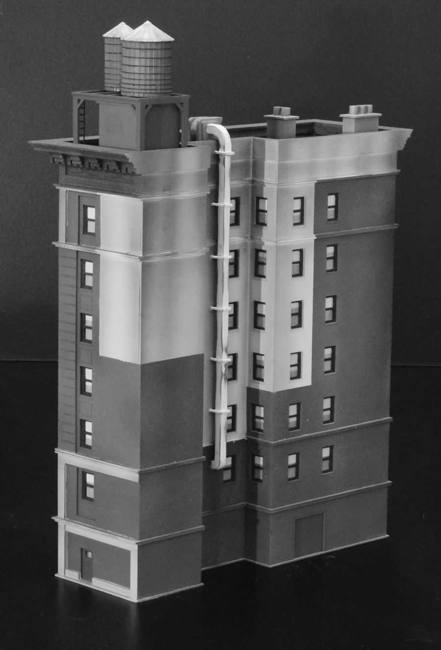
20 Final Assembly Now that you have built all of the building units, it is time to assemble them. Make sure that the bottom and top of each unit is perfectly flat and smooth. Sand or file any imperfections off as necessary. Glue the units together one at a time and allow to dry before proceeding to the next unit. You can run a bead of glue along the cornice where the two pieces meet. The interior rectangular openings should align from one unit to the next. Continue gluing the units together in this fashion making sure that everything is straight and true as you go along. Once completed touch up any glue and paint imperfections along the cornices. Glue the roof details on the roof as shown in Figures 32 & 33. Glue the Exhaust Unit on the roof so that the curved duct goes over the wall and down into the back air shaft. Glue the duct assemblies to the curved duct and run them down the wall using the brackets (E-9) to hold them in place. The duct with the curved end goes on the bottom and should run back into the wall. See reference images on the following pages. Glue the fire escapes to the side of the building. Sidewalk material is included to glue around the building base. Your building is finished and ready to install on your layout. You may add lights and other details. We thank you for purchasing this kit from CMR and hope that you have enjoyed building it. Be sure to see our other kits at 20
21 21
22 22
23 Rubley Building Parts N Page 1 Unit 1 Parts A A B B (1-1) (1-2) (1-3) (1-4) (1-5) (1-6) (1-7) (1-8) (1-9) (1-10) (1-11) (1-12L) x2 (1-12C) x2 (1-12R) x2 (1-13L) (1-13R) (1-14) x2 (1-15) (1-16) (1-17) (1-18) x2 (1-19) Adhesive backed styrene. CMR 2016
24 Rubley Building Parts N Page 2 Unit 2 Parts C C D D (2-1) (2-2) (2-3) (2-4) (2-5) (2-6) (2-7) (2-8) (2-9) (2-10) (2-11) (2-12) (2-13) (2-14) (2-15) x3 (2-16) (2-17) x2 (2-18) x3 CMR 2016
25 Rubley Building Parts N Page 3 Unit 3 Parts E E F F (3-1) (3-2) (3-3) (3-4) (3-5) (3-6) (3-7) (3-8) (3-9) x5 Wide Column (3-10) x2 Thin Column (3-11) x16 (3-12) (3-13) x3 (3-14) x2 (3-14) x3 CMR 2016
26 Rubley Building Parts N Page 4 Unit 4 Parts G G H H F F (4-1) (4-2) (4-3) (4-4) (4-5) (4-6) (4-7) (4-8) (4-9) (4-10) (4-11) (4-12L) x2 (4-12C) x3 (4-12R) (4-13L) (4-13R) (4-14) x4 (4-15) x3 (4-16) (4-17) x2 (4-18) x3 CMR 2016
27 Rubley Building Parts N Page 5 Unit 5 Parts I I J J (5-1) (5-2) (5-3) (5-4) (5-5) (5-6) (5-7) (5-8) (5-9) (5-10) (5-11) (E-1) x1 (E-2) x2 (E-3) x2 (E-4) x2 (E-5) (E-6) (E-7) x2 (E-8) x4 (E-9) x2 (E-10) x8 CMR 2016
28 Rubley Building Parts N Page 6 Unit 6 Parts K K (R-1) (R-2) (R-3) (R-4) L L (R-5) (R-6) (R-7) (R-8) M M (R-9) x2 (R-10) x2 (R-11) (C-1) x2 N N (C-2) x2 (C-3) x2 (C-4) O O (C-5) x2 (C-6) x2 (C-7) x2 P (C-8) CMR 2016
The Fyfe Building Instructions for Assembly of the N scale kit.
 The Fyfe Building Instructions for Assembly of the N scale kit. Kit Contents: 150 each laser cut 1/16" acrylic parts. 6 each 020 adhesive backed part 6 each column caps 2 each decorative canopy 1 each.125"
Hotel Belvedere Instructions for Assembly of the HO scale kit. v1.1
 Hotel Belvedere Instructions for Assembly of the HO scale kit. v1.1 Kit Contents: 319 ea. laser cut.090" acrylic parts. 132 ea. laser cut.060" acrylic parts. 8 ea. window glass templates 8 ea. window glazing
The Midtown Apartment Building
 The Midtown Apartment Building Instructions for Assembly of The Midtown Apartment Building. Kit Contents: 70 each laser cut acrylic parts. 3 each sidewalk parts. 3each Window Glass Templates, 3 each Window
The Park Hotel Instructions for Assembly of N Scale Kit
 The Park Hotel Instructions for Assembly of N Scale Kit Kit Contents: 198 ea. Laser Cut Acrylic Parts, 2 ea. Chimney Parts Sheets, 1 ea.2".040 styrene rod, 5 ea. Sidewalk Parts, 14 ea. Cast Resin Dormers,
The Park Hotel Instructions for Assembly
 The Park Hotel Instructions for Assembly Kit Contents: 280 ea. Laser Cut Acrylic Parts. 1 ea. 6" Plastic Coated Wire. 5 ea. Sidewalk Parts. 14 ea. Cast Resin Dormers. 12 ea. Window Glass Templates, 12
The Saint Paul Building
 The Saint Paul Building Instructions for Assembly of The Saint Paul Building. Kit Contents: 65 each laser cut acrylic parts. 1 each sheet of AC roof unit parts. 1 each sidewalk. 3 each Window Glass Templates,
Fidelity & Guaranty Building
 Fidelity & Guaranty Building N Scale Model Kit Instructions for Assembly of the Fidelity & Guaranty Building Kit Contents: 69 each laser cut acrylic parts. Sidewalk material 1 each Window Glass Templates
Fidelity & Guaranty Building
 Fidelity & Guaranty Building Instructions for Assembly of the Fidelity & Guaranty Building Kit Contents: 69 each laser cut acrylic parts. 1 each sheet of AC roof unit parts. 1 each sidewalk base. 4 each
Donaldson s Department Store
 Donaldson s Department Store Instructions for Assembly of Donaldson s Department Store Kit Contents: 80 each laser cut acrylic parts. 1 each sheet of canopy parts. 1 each sheet of AC roof unit parts. 1
The Severn Instructions for Assembly of the N scale kit.
 The Severn Instructions for Assembly of the N scale kit. Kit ontents: 172 each laser cut 1/16" acrylic parts 102 each adhesive backed styrene parts 1 each cast entryway 3 each cast balcony 4 each cast
Drawings of all parts have been included for ease of part identification.
 Acme Corporation Instructions for Assembly of the HO Scale Acme Corporation HO Kit Contents: 156 ea. white 1/16" laser cut acrylic part 10 ea. white 1/8" laser cut acrylic part 37 ea. adhesive-backed brick
Instructions for Assembly of the HO Scale The Charles
 The Charles Instructions for Assembly of the HO Scale The Charles HO Kit Contents: 337 ea. white 1/16" laser cut acrylic part 19 ea. Clear 1/16" laser cut acrylic part 69 ea. white 1/8" laser cut acrylic
If by chance a part is missing or broken please contact us indicating the kit name and part description and we will send you a replacement.
 Six Stall Roundhouse Instructions for Assembly of the HO Scale Six Stall Roundhouse Roundhouse Kit Contents: 18ea. Roof Pieces 12 ea. 1/16" Parts Sheets 9ea. 1/8" Parts Sheets 12ea. Floor Pieces 1ea. 1/4"
Nanton Grain Mill Assembly
 ( 1 ) Nanton Grain Mill Assembly Locate package for assembling storage building. These are cut from 1/8 masonite. Inspect and lightly sand edges where it will be bonded. Use white glue or CA glue to bond.
Hardee s Restaurant kit in HO scale
 Hardee s Restaurant kit in HO scale Parking lot base and cars not included This kit includes all building parts milled in white styrene plastic and laser cut white acrylic, clear acrylic window glazing,
CVS Pharmacy kit in HO scale
 CVS Pharmacy kit in HO scale Parking lot base and cars not included This kit includes all building parts and wall-mounted signs milled in white styrene plastic, clear window glazing and pre-cut Plastruct
Tools and Tips: ( 1 )
") Tools and Tips: As you build instructions will show in my many picture manual how to assemble. You can use your own methods as you desire, my results are very good. A smooth, flat work surface is very
Tools and Tips: As you build instructions will show in my many picture manual how to assemble. You can use your own methods as you desire, my results are very good. A smooth, flat work surface is very
Tools and Tips: ( 1 )
") Tools and Tips: As you build the book will show in my many picture manual how to assemble. You can use your own methods as you desire, but these worked best for me. A smooth, flat work surface is very
Tools and Tips: As you build the book will show in my many picture manual how to assemble. You can use your own methods as you desire, but these worked best for me. A smooth, flat work surface is very
Taco Bell Restaurant kit in HO scale
 Taco Bell Restaurant kit in HO scale Parking lot base and cars not included This kit includes all building parts milled in white styrene plastic, clear window glazing, Plastruct tile roofing, and logo
CONCEPT MODELS INSTRUCTIONS FOR UP DC-10 WING CAR El Toro Way Stockton, CA Web Address:
 CONCEPT MODELS Web Address: http://www.con-sys.com 8810 El Toro Way Stockton, CA 95210 INSTRUCTIONS FOR UP DC-10 WING CAR 2 CONCEPT MODELS PARTS DC-10 WING CAR Item No. Part No. DESCRIPTION QTY. 1 2003-1
DAVENPORT DEPARTMENT STORE PF5214
 1:160 BUILDING KIT DAVENPORT DEPARTMENT STORE PF5214 Dress up your downtown scene with the classic Victorian architecture and large first-floor picture windows of the Davenport Department Store. Details
The Hamlin Assembly Instruction By Laser Dollhouse Designs
 The Hamlin Assembly Instruction By Laser Dollhouse Designs NOTE 1: Please do a dry assembly using only tape to hold house together. This will get you familiar with parts, location, and fit. This also gives
CORNER PORCH HOUSE PF5196
 1:87 BUILDING KIT CORNER PORCH HOUSE PF5196 Two-story home with cedar-shake roof and a corner wrap-around porch. Clapboard siding, paned windows, and loaded with accessories, such as a bicycle built for
5If the protruding part is. 6Place 1 as is shown in the. 7Place what was assembled
 Yamato: Step-by-step 49 The base of the bridge and strakes a c b d a Base of the bridge b Base of the bridge c Base of the bridge d Strakes x 10 THE BASE OF THE BRIDGE 1Smooth 1 to 3, first using the metal
Railroad Kits PO Box 461 Holden, MA
 (Formerly Downtown Deco DD 1004 Fallburg Station) HO Scale. Thanks for purchasing one of my kits. Because different people have different degrees of experience, I'll walk you through, step by step, explaining
SUGAR CREEK HOTEL PHOTO REAL BUILD KIT
 SUGAR CREEK HOTEL PHOTO REAL BUILD KIT by Innovative Hobby Supply INSTRUCTIONS FOR: Kit BK 6407 Sugar Creek Hotel Build Kit ~ S scale Free replacement parts are available simply by calling 866 712 4059.
Seascape Bungalow Assembly instructions. Laser Dollhouse Designs
 Seascape Bungalow Assembly instructions Laser Dollhouse Designs NOTE: Please do a dry assembly using only tape to hold house together. This will get you familiar with parts, location, and fit. This also
1Take the keel (3) and
 and") 1 The hull and the bridge 1Take the keel (3) and apply PVA wood glue in the second slot from the left: a toothpick may make it easier. Take care: the left end is the one that has a projection. THE HULL
1 The hull and the bridge 1Take the keel (3) and apply PVA wood glue in the second slot from the left: a toothpick may make it easier. Take care: the left end is the one that has a projection. THE HULL
Continued on next page
 Please read these instructions completely through to be sure you are familiar with all the steps. Then following along again as you build your structure. Download a.zip file of all the pictures including
BUZZ S SAWMILL PF5195 WOODLAND SCENICS BUILDING KIT
 1:87 BUILDING KIT BUZZ S SAWMILL PF5195 Buzz s Sawmill is a detailed work of art with all workings of a vintage steam-fired, belt-driven sawmill. Details include interior rafters and shake roof, attached
Shell Gas Station & Convenience Store kit in HO scale
 Shell Gas Station & Convenience Store kit in HO scale Parking lot base and cars not included This kit includes all building parts and signs milled in white and black styrene plastic, clear window glazing,
Instructions and Assembly Guide
 Corona Concepts presents The Creekside Cabin All Wood Dollhouse 1997 Corona Concepts Schenevus, NY 12155 All rights reserved These instructions were printed in New York State Instructions and Assembly
Additional Parts List:
 THE TIME MACHINE Additional Parts List: In addition to the cast resin parts enclosed in this kit, there should also be a plastic bag containing the following items needed to complete your time machine
Modern Gas Station backdrop building kit in HO scale
 Modern Gas Station backdrop building kit in HO scale This kit includes all building parts, pumps, signs, and base milled in white styrene plastic, clear window glazing, Plastruct Ridgid Clay Tile roofing,
3Insert the second rod no. 4
 Yamato: Step-by-step 37 The stern block and searchlight control towers a b c d e f Recommended tools and materials Wood glue Sandpaper (no. 800 grain) Metal file Putty Craft knife For metal: Super Glue
Assembly Instructions for Summit Motel Kits # SMFS and SMBD
 Assembly Instructions for Summit Motel Kits # SMFS and SMBD Introduction Thank you for your purchase of the Summit Motel. This modern motel can be converted to almost any chain motel of your choice, depending
Cockpit Kit. Full Depth - Builds Quickly - Light Weight READ THROUGH THIS INSTRUCTION MANUAL FIRST. IT CONTAINS IM- laser cut wood kit
 The Savage Light Sukhoi Su- 27 Cockpit Kit contains everything you need to build a full depth semi scale Su-27 cockpit, yet adds less than an ounce to your finished model s weight (not including pilot).
Rural Shamrock Gas Station & Store kit in HO scale
 Rural Shamrock Gas Station & Store kit in HO scale Parking lot base and cars not included This kit includes all building parts and signs milled in white and black styrene plastic, clear window glazing
HARRISON S HARDWARE PF5891
 1:48 BUILDING KIT HARRISON S HARDWARE PF5891 Model the local hardware store where layout residents can find all they need to keep their homes in tip-top shape and workshops running smooth. The positive
CONCEPT MODELS SP DOUBLE STACK CONTAINER CARS INSTRUCTIONS Sheep Ranch Rd. Mountain Ranch, CA Web Address:
 CONCEPT MODELS Web Address: http://www.con-sys.com 8331 Sheep Ranch Rd. Mountain Ranch, CA 95246 SP DOUBLE STACK CONTAINER CARS INSTRUCTIONS 2 CONCEPT MODELS PARTS Item No. PART NO. DESCRIPTION QTY. 1
 Allied Tool is a freelance model of a small manufacturing company that grew from production in a home basement to a new building. Assume a gentleman starts assembling gauges in his basement and the business
Vivian Mansion Assembly Instruction By Laser Dollhouse Designs
 Vivian Mansion Assembly Instruction By Laser Dollhouse Designs NOTE 1: Please do a dry assembly using only tape to hold house together. This will get you familiar with parts, location, and fit. This also
1Smooth pieces 4, 5 and 6, using
 Yamato: Step-by-step 109 Machine-guns, anti-aircraft guns and decking h e f a b c g d e f a Anti-aircraft gun base x 2 b Anti-aircraft gun (bottom) x 2 c Anti-aircraft gun (top) x 2 d Machine-gun base
EXTREME LOAD no. TWO
 1602 - EXTREME LOAD no. TWO Kit Features: 22' 4 " x 14' x 3'-6 Oversize Load 49mm (1.9") actual height Bolt Head Details Welded Load Mounting Fins Painting Handles Tools Required: Hobby Knife Tweezers
CONCEPT MODELS INSTRUCTIONS FOR THE KASGRO KRL SPECIAL DEPRESSED CENTER FLAT CARS El Toro Way Stockton, CA 95210
 CONCEPT MODELS Web Address: http://www.con-sys.com Email: concept_models@con-sys.com 8810 El Toro Way Stockton, CA 95210 INSTRUCTIONS FOR THE KASGRO KRL 204000-2 SPECIAL DEPRESSED CENTER FLAT CARS 2 CONCEPT
The Gothic Chess Set
 The Gothic Chess Set Please note that this chess set is a fairly difficult and time consuming project. I strongly suggest building one or two easier models before tackling this one! The miniatures used
Little Briana Cottage Dollhouse assembly instructions
 Little Briana Cottage Dollhouse assembly instructions NOTE 1: Please do a dry assembly using only tape to hold house together. This will get you familiar with parts, location, and fit. This also gives
KIT BUILDING ED SCHULTZ
 KIT BUILDING ED SCHULTZ KIT BUILDING FIVE BASIC MATERIALS: PLASTIC (STYRENE) WOOD LASER CUT & STANDARD PLASTER METAL RESIN ADDING DETAILS PLASTIC KITS TYPICALLY STYRENE TYPE PLASTIC DPM WALTHERS BACHMANN
J.W. cobbler 1:160 BUILDING KIT PF5210 WOODLAND SCENICS
 1:160 BUILDING KIT J.W. cobbler PF5210 The partially assembled walls, positive alignment system and prefinished edges make kit assembly quick, easy and accurate. This three-story brownstone features stacked
(Build Instructions)
") (Build Instructions) Specifications * Wingspan: 58cm * Length: 50cm * Flying Weight: 59 grams * Channels: 3 (Rudder Elevator Throttle) * Suggested Receiver: 4Ch Micro * Motor: 8mm GearDrive * Prop: GWS
(Build Instructions) Specifications * Wingspan: 58cm * Length: 50cm * Flying Weight: 59 grams * Channels: 3 (Rudder Elevator Throttle) * Suggested Receiver: 4Ch Micro * Motor: 8mm GearDrive * Prop: GWS
G. Building the Cab, Cab Roof and Cab Boiler Extension Page 14 and Backhead.
 G. Building the Cab, Cab Roof and Cab Boiler Extension Page 14 and Backhead. Cab. In order to ensure that the cab and tender would actually look right, as what often appears on a drawing is not always
Cardboard Model Buildings
 Cardboard Model Buildings Get more model kits from http://www.modelbuildings.org PRINTING & ASSEMBLY TIPS: These OO designs can easily be resized by reducing the print percentage as follows: OO scale is
Corona Concepts presents The Lily All Wood Dollhouse. Instructions and Assembly Guide
 Corona Concepts presents The Lily All Wood Dollhouse Instructions and Assembly Guide Introduction In Short... Welcome to the exciting world of dollhouses and miniatures. Since the first tab and slot die-cut
N Scale Concrete Coal Dock Instruction Manual
 N Scale Concrete Coal Dock Instruction Manual 1. General Overview This kit combines precision laser cut acrylic, photo etched brass and wood parts to make a highly detailed model of the Roberts and Schaefer
Subway building kit in HO scale
 Subway building kit in HO scale This kit includes all building parts and signs milled in white and black styrene plastic, clear window glazing, and self-adhesive decals. All parts fit together but may
Continue gluing the remaining top parts ensuring the angled piece is glued well. Set aside and let dry. See photo below
 Radiator rev 1.1 The SE5a s radiator is one of the most recognized radiators in WW1. It is one of the components that defines the SE5a. The original SE5a has seen multiple radiator designs used during
Model Grandma and Grandpa s cozy cottage, a. Country Cottage Instructions HO Scale 1:87 WOODLAND SCENICS PF5186
 PF586 Country Cottage Instructions HO Scale :87 Model Grandma and Grandpa s cozy cottage, a young family s first home or give this vintage Victorian cottage the run-down look of an abandoned shack. This
LASER-ART. The DuBois House. LASER-ARTSTRUCTURES by BRANCHLINE TRAINS BRANCHLINE TRAINS STRUCTURES
 LASER-ARTSTRUCTURES by BRANCHLINE TRAINS LASER-ART STRUCTURES by BRANCHLINE TRAINS The DuBois House History With their gingerbread trim and ornate decoration the Queen Anne style is what most people imagine
Building the Gothic Church
 Building the Gothic Church Mold #54 does not contain all of the blocks to build this church. You will need extra regular blocks (1/2" x 1/2" x 1") and square blocks (1/2" x 1/2" x 1/2"). These blocks can
Craftman One Car Garage Assembly Instruction by Laser Dollhouse Designs
 Craftman One Car Garage Assembly Instruction by Laser Dollhouse Designs NOTE 1: Please do a dry assembly using only tape to hold house together. This will get you familiar with parts, location, and fit.
The Lansdowne One Car Garage Assembly Instruction by Laser Dollhouse Designs
 The Lansdowne One Car Garage Assembly Instruction by Laser Dollhouse Designs NOTE 1: Please do a dry assembly using only tape to hold house together. This will get you familiar with parts, location, and
Corona Concepts presents The Laurel All Wood Dollhouse. Instructions and Assembly Guides
 Corona Concepts presents The Laurel All Wood Dollhouse Instructions and Assembly Guides Introduction In Short... Welcome to the exciting world of dollhouses and miniatures. Since the first tab and slot
Ben Franklin 5&10 Store
 Ben Franklin 5&10 Store RIVER LEAF MODELS, LLC RIVER LEAF MODELS, LLC Thank you for purchasing the Ben Franklin 5&10 structure kit. Your kit includes everything you need to assemble the final product.
Cobra X Q Construction Tips Construction: Bel y pan
 Cobra X Q Construction Tips : The white plastic in this kit is high impact styrene. It can be painted with most types of coatings if light coats are applied this is necessary due to the thickness of the
Darjeeling Coach 4-Wheel First/Second Class
 Darjeeling Coach 4-Wheel First/Second Class Introduction This kit was designed in 16mm scale from early Darjeeling drawings and photographs. It uses brass castings available from Brandbright. The instructions
FRANKLIN COUNTY 4-H MODEL BUILDING
 FRANKLIN COUNTY 4-H MODEL BUILDING Save this book, use it each year you are in the project. 4 H Model Building Model building can be fun and exciting. You can express your creative abilities, learn to
Domino's Take-out Pizza building kit in HO scale, latest design
 Domino's Take-out Pizza building kit in HO scale, latest design This kit includes all building parts and signs milled in white and black styrene plastic, clear window glazing, and self-adhesive decals.
3Position the hull of the ship as
 Yamato: Step-by-step 25 The hull and stern deck c b d a b d c e e f a Rear frame b Stern deck x 2 c Stern deck x 2 d Side wall x 2 Wood glue Sandpaper (no. 400 grain) Craft knife Pliers d Side wall x 2
(56501) Corona Concepts presents The Willow All Wood Dollhouse. Instructions and Assembly Guide RTD AA
 Corona Concepts presents The Willow All Wood Dollhouse. Instructions and Assembly Guide RTD AA") (56501) Corona Concepts presents The Willow All Wood Dollhouse Instructions and Assembly Guide RTD10000572AA Introduction In Short... Welcome to the exciting world of dollhouses and miniatures. Since the
(56501) Corona Concepts presents The Willow All Wood Dollhouse Instructions and Assembly Guide RTD10000572AA Introduction In Short... Welcome to the exciting world of dollhouses and miniatures. Since the
Corona Concepts presents The Buttercup All Wood Dollhouse. Instructions and Assembly Guides
 Corona Concepts presents The Buttercup All Wood Dollhouse Instructions and Assembly Guides Introduction In Short...Welcome to the exciting world of dollhouses and miniatures. Since the first tab and slot
Thank you for purchasing E.L. Moore Window & Door.
 Thank you for purchasing E.L. Moore Window & Door. Instructions Version 4.28.15 I ve named this kit after one of the greatest modelers I ve ever known, the late Elliot Moore Jr. Rest in peace my friend.
After printing these plans, several pages will need to be taped together to form a larger plan. Below is a diagram of which pages need assembled.
 Watermill Building Plans For complete building instructions and instructional videos, please visit the main web site at www.hirstarts.com/watermill/watermill.html. Using these plans alone will not give
La Grange, Texas MKT Depot kit in HO scale
 La Grange, Texas MKT Depot kit in HO scale This kit includes all building parts laser cut in plywood, white and clear acrylic, and laser cut self-adhesive shingles. All parts fit together but may need
Instructions For Corrugated End Van
 Instructions For Corrugated End Van This kit contains the following items QTY ITEM QTY ITEM QTY ITEM 1 Floor 2 Van Ends 1 Roof 2 Van Sides 2 Sole Bars 4 Axle Boxes 4 Bearings 2 Coupling Hooks 2 Split Pins
CONCEPT MODELS UTLX 80006,80020 CRYOGENIC TANK CAR KIT INSTRUCTIONS Sheep Ranch Rd. Mountain Ranch, CA 95246
 CONCEPT MODELS Web Address: http://www.con-sys.com Email: concept_models@con-sys.com 8331 Sheep Ranch Rd. Mountain Ranch, CA 95246 UTLX 80006,80020 CRYOGENIC TANK CAR KIT INSTRUCTIONS 2 CONCEPT MODELS
Instructables Butcher Block Top
 Instructables Butcher Block Top Project Overview: This project requires basic woodworking skills and access to woodworking machines. Woodworking machines have sharp cutting edges and are NOT forgiving.
The Reading Tug Schuylkill By: Barry Hensel
 The Reading Tug Schuylkill By: Barry Hensel My Reading Lines Central Division layout has needed a tug boat for the Port Richmond coal dock scene for some time. I finally found a Walthers Tug kit for a
Roof Contour By Bob Parrish
 Roof Contour By Bob Parrish This text will show you how to shape the roof contour on Labelle passenger and trolley kits. The height of the clerestory on the two types of kits is different. Passenger kits
WRIGHT FLYER 1 INSTRUCTIONS FOR THE D10LC KIT
 WRIGHT FLYER 1 INSTRUCTIONS FOR THE D10LC KIT Manufactured in the USA by Easy Built Models PO Box 681744, Prattville, AL 36068-1744 Visit us at www.easybuiltmodels.com Easy Built Models GLUE METHODS Always
How to assemble the Reims Gueux Pit Centre Module #005
 How to assemble the Reims Gueux Pit Centre Module #005 We recommend quick drying super glue for our models. Just a few drops on the joining edges, press and hold them for a few seconds and the connection
Model the hub of your layout s rural setting. Planters Feed and Seed Supply Instructions N Scale 1:160 WOODLAND SCENICS
 PF5201 Planters Feed and Seed Supply Instructions N Scale 1:10 Model the hub of your layout s rural setting. Planters Feed and Seed Supply presents a vintage agricultural center where farmers and rural
BUILD THE. Soleil Royal. Pack 1. The flagship of King Louis XIV.
 BUILD THE Soleil Royal The flagship of King Louis XIV www.model-space.com Pack 1 Stage 1 Assembly Guide Hull frame, false keel and first deck half A 4 2 5 1 6 7 1A Smooth the surfaces of all the pieces
CONCEPT MODELS INSTRUCTIONS FOR PRODUCT 60,000 GALLON TANK CAR El Toro Way Stockton, CA 95210
 CONCEPT MODELS Web Address: http://www.con-sys.com Email: concept_models@con-sys.com 8810 El Toro Way Stockton, CA 95210 INSTRUCTIONS FOR PRODUCT 60,000 GALLON TANK CAR 2 CONCEPT MODELS PARTS GATX/UTLX
A Day House. A View of One Way to Finish the Exterior of The Day House. Read these instructions all the way through before beginning this project.
 A Day House A View of One Way to Finish the Exterior of The Day House Read these instructions all the way through before beginning this project. General Comments For the purposes of this project, the standard
MUDGUN Drywall Finishing System
 Watch the demonstration video online at hydetools.com MUDGUN Drywall Finishing System Quick Start Guide Hyde Tools, Inc. / A Hyde Group Company / 800-872-4933 / custrelations@hydetools.com / hydetools.com
Building the Bell Tower
 Building the Bell Tower Mold #55 does not contain all of the blocks to build this tower. You will need extra regular blocks (1/2" x 1/2" x 1") and square blocks (1/2" x 1/2" x 1/2"). These blocks can be
PS 5077 cu. ft. Boxcar with EOC device. 1:29 scale resin craftsman kit. by Burl Rice
 PS 5077 cu. ft. Boxcar with EOC device 1:29 scale resin craftsman kit by Burl Rice www.burlrice.com Bill of materials (not included): Thick/medium viscosity CA PL adhesive, or Gorilla Glue Heavy Duty Construction
How to assemble the Reims Gueux Pit End Modules #005
 How to assemble the Reims Gueux Pit End Modules #005 Depending on which kit you have purchased you will either have a pair of end sections, some centre sections or both. We will describe building of the
1Use the metal file to smooth
 Yamato: Step-by-step 85 Parts of the bridge and the hull a b c d e f a Part of the bridge b Part of the bridge c Part of the bridge d Radar x 2 e Part of the bridge x 2 f Wire Recommended tools and materials
STONEYBRIDGE STRUCTURES
 02-208-OO North Eastern Railway N2 Style Signal Box INTRODUCTION Thank you for purchasing one of our products. We hope this information sheet will prove useful in the construction of this model. We have
Lowe's backdrop building kit in HO scale
 Lowe's backdrop building kit in HO scale Parking lot base, lawn mowers and cars not included This kit includes all building parts and signs milled in white styrene plastic and clear window glazing. Plastruct
Wayside Cottage Assembly Instructions By Laser Dollhouse Designs
 Wayside Cottage Assembly Instructions By Laser Dollhouse Designs Parts for assembly Base Floor marked 1A thru 1L 13 post and 11 fences With one gate Walls 1A thru 1L and Alcove roof panels 3 lg and 1 sm
28 ft. Ventilated (Combination) Box Car
 Box Car") 28 ft. Ventilated (Combination) Box Car Introduction This laser cut wood kit is an HO scale model of a 28 ft. Ventilated (also known as a Combination) Box Car. The model is based on the Illinois Central
28 ft. Ventilated (Combination) Box Car Introduction This laser cut wood kit is an HO scale model of a 28 ft. Ventilated (also known as a Combination) Box Car. The model is based on the Illinois Central
Noville School Diorama Part 4 Making the Floors and Plastering the Walls and Ceilings
 Noville School Diorama Part 4 Making the Floors and Plastering the Walls and Ceilings Moulds and Materials Making the Floors Plastering the Ceiling Plastering the Walls Installing the Ceiling and Floor
RACETRACK BLEACHERS PHOTO REAL BUILD KIT
 RACETRACK BLEACHERS PHOTO REAL BUILD KIT by INSTRUCTIONS FOR: Kit BK 6402 Racetrack Bleachers Build Kit ~ S scale Free replacement parts are available simply by calling 866 712 4059. Includes two (2 ea.)
Installation Instructions
 Installation Instructions Follow these simple instructions to install your OneDayCab! IMPORTANT: Unpack and check shipment for damage. Verify color, size and parts before demolition. Installation of interiors
Installation Instructions Palladium 3D Hi Impact Wall System, Partial Height with Color Matched Caulk Joints
 Please read all instructions before installing Palladium 3D Hi Impact Wall System.. Before installation: a. Acclimate rigid sheet, Palladium 3D boards, adhesives and wall substrates to room temperature
Installation Instructions
 Aspex Digitally Printed Wall Art PL PREMIUM HEAVY DUTY ADHESIVE ASPEX WALL ART DOUBLE SIDED FOAM TAPE Installation of Aspex Digitally Printed Wall Art with Foam Tape and PL Premium Adhesive. Maximum size
ParkJet Builder s Manual
 ParkJet Builder s Manual Thank you for purchasing the ParkJet. The ParkJet is a profile ducted fan airplane that can be flown in a larger park. The ParkJet was initially designed by Scott Stoops and modified