LA LIBERTÉ DE CONCEVOIR. Modular transfer systems
|
|
|
- Frederica Lane
- 5 years ago
- Views:
Transcription

1 Modular transfer systems


2 FRENCH INDUSTRIAL LEADER has brought innovating solutions to the industry. Our approach offers a complete freedom of design thanks to a unique range of flat belt conveyor and modular transfer systems. EXCLUSIVE PARTNER Our partnership with the German company since 1986 has opened a large expertise field and a worldwilde recognized network. elcom s flat belt conveyor design, constructed from item s range of profiles, enables a great modularity. GEOGRAPHICAL PRESENCE Europe Denmark France Finland Germany Norway Italy Sweden Benelux Spain North America USA Canada South America Australia Asia China India Malaysia Singapore COMPLETE RANGE AND NEW PRODUCTS Our creations result from a large range of products which is regularly enlarged by novelties. They offer unlimited possibilities in terms of industrial modularity. SERVICES x Strong production capacity and very high reactivity x Important stock, fast delivery x Preparation for kit delivery x Assembly of complete sets x Quotations based on customers drawings and sketches x Technical advice x CAD files library x Fast prototype abilities
3 Modular transfer systems elcom s modular transfer systems, built from item s range of profiles enable a great modularity. Modular industrial system adapted for the realization of your assembly lines with automatic or manually operated work stations. Workpiece carriers are conveyed on two parallel belts which facilitate the implementation of stoppers, positioning units, accessories... Retractable pins, located under the workpiece carrier, allow: > guiding the workpiece carrier with 4 pins on straight sections, > guiding the workpiece carrier round bends with 2 pins (the other being retracted). The perfect complementarity between transfer systems, profiles and flat belt conveyors will facilitate the solving and realization of your ideas. TRANSFERS TLM 1000, 1500, 2000,

4 TRANSFER LA LIBERTÉ DE CONCEVOIR 4

5 TRANSFER LA LIBERTÉ DE CONCEVOIR Example of transfer ITS 24 V TLM 1500 with : workpiece carriers 150x150 motorization 24 V positioning units 24 V stoppers 24 V 5
6 TRANSFER - INNOVATIONS TECHNOLOGICAL INNOVATIONS Transfer system elcom ITS 24 V New concept 24 V future-oriented elcom ITS 24 V is a new, ingenious elcom concept which provides numerous advantages: Low energy consumption Reduction of sound level (electric distributor valves are removed) Concept Plug and Play Cost saving installation, cost reduction of commissioning and integration Easy to use, it is possible to control the system with a network (bus system) this logo allow to identify easily components which belong to this concept, inside the catalog. It is also easy to use: Electronic control of the motor parameters (acceleration, speed, slowdown), Can be directly controlled by a network (bus system), Cams of actuators can be adjusted by potentiometer. It is now possible to stop the motor at any moment without any damage risk. The speed can be adjusted directly into the motor with a simple computer. No air which means : no dust/ no oil. 6 Important : the new elcom ITS 24 V concept is perfectly suitable to use with the elcom pneumatic transfer system. All parts are modular, the user can choose what he prefers.
7 Transfer system elcom ITS 24 V - Comparative table of energy consumptions 24 V 380 V ENERGY Load< 1Kg Load=10kg Load=20Kg Load=30Kg Power STOPPER-CAM-24 V servomotor < 1 w < 1 w < 1 w < 1 w 0,15 sec/cycle STOPPER-CAM-Pneumatic VALVE 6 w 6 w 6 w 6 w 0,4 sec/cycle TLM 1500 MOTOR FOR UNIT 24 V 7,2 w 11,3 w 13,7 w 18,5 w can be stopped TLM 1500 MOTOR FOR UNIT 400 V 150 w >150 w >150 w >150 w permanent Sample for a loop working 3x8 shifts- 48 weeks --> the machine runs hours TRANSFER - INNOVATIONS Cycle time = 6 sec 12 motors 20 stoppers Kwxh cost = 0,24 Hours nb Power Cost/hour Cost 20 x Stoppers 24 V ,001 0,24 2,47 20 x Pneumatic stoppers ,006 0,24 39,42 12 x Motors 24 V average 10 W ** ,010 0,24 179,37 12 x Motors 400 V average 180 W ,180 0, ,20 Cost-saving (per year) Conveying units 24 V can be stopped when work stations are saturated. To have a maximum economic benefit, it is advisable to place upstream saturation detectors as close as possible of work station. Energy reporting on a TLM 1500 Power calculation TLM Loads in accumulation For 9 m/min: 0 kg : 450 ma -> 10,8 W 10 kg : 850 ma -> 20,4 W 20 kg : ma -> 31,2 W 50 kg : ma -> 57,6 W Energy reporting for elcom GmbH 7

8 TRANSFER - INNOVATIONS TECHNOLOGICAL INNOVATIONS Transfer system elcom ITS 24 V TLM

9 Transfer system Module Heavy loads Module Heavy loads is an option integrated into the guide belt which enables to increase the performances of the transfer TLM. It is fitted instead of the standard guide belt. TRANSFER - INNOVATIONS The benefits of this option are numerous: Significant increase of the load carried by the transfer (x2.5 the nominal load) Easy and quick installation of modules in existing units Great modularity: quick replacement of standard guiding belt by Module Heavy loads with the possibility to combine them Important: the new Module Heavy loads can be perfectly combined with the elcom transfer range TLM 2000 flat belt. 9

10 TRANSFER The operating principle of workpiece carriers Our transfer systems operate with standard workpiece carriers on which a customized fitting of conveyed workpiece is fixed. Combined with transport units, stoppers, positioning units, lifts and many standard modules, our workpiece carrier systems offer many lay-outs for transport and part supply. elcom differentiates itself from traditional transfer sytems through an ingenious system of retractable pins located under the workpiece carrier (shown in red). They enable the workpiece guidance in straight lines and to make curves in cams. Results: low cost of implementation with a simplified automation, a better flow of workpiece carrier, a reduced cycle time and reduced number of workpiece carriers. Two main tasks are fulfilled: The first task is the transport and the management of workpiece carriers. This is done by means of transport modules based on double belt conveyors. The conveying of workpiece carriers to the desired location is carried out through cams, standard returns and lifts. The second task is the stop and the positioning of workpiece carriers. These are provided by stoppers (e.g. manual supply of workpiece carriers) and positioning units (e.g. robot loading). Standard modules are provided for each specific stage of the process (e.g. press positioning unit, returns...). 10 The benefits of this well-designed concept can also be noticed in the servicing and maintenance as less actuators and parts have to be maintained. Moreover, maintenance work can be carried out even on an operating machine, which helps keeping the production line available.
11 Overview of technical data Workpiece carriers (mm) 105 x 105 TLM 1000 TLM 1500 TLM 2000 TLM x x x x x x x x x x x 1000* 600 x x x 1000* 800 x x 1000 (*option 1500) TRANSFER Load/workpiece carrier (dan) Speed (m/min) Flat belt Timing belt Length of conveying unit Mini Maxi Maxi accumulation load per motor (dan) (heavy) (light) Flat belt Timing belt Absolved maximum load (dan) (without accumulation) Flat belt Timing belt 25 / 3 m 35 / 3 m 35 / 3 m 50 / 3 m Motor power flat belt (380 V three-phase) 0,09 KW-0,4 A 70 / 3 m 70 / 3 m Motor power timing belt (380 V three-phase) 0,09 KW-0,4 A 0,09 KW-0,4 A V V / 6 m 60 / 6 m (direct) 60 / 6 m (light) 150 / 6 m (heavy) 200 / 6 m 120 / 6 m (direct) 120 / 6 m (light) 300 / 6 m (heavy) 400 or 75 % KW 0,25 0,37 0,55 KW 0,55 A 0,68 1,24 1,60 A 1,60 0,25 KW - 0,83 A Note: Solutions exist to handle larger loads per workpiece carrier. A complete system customization of the configuration (layout, cycle time, etc.) is possible after consultation with our technical office. Please contact us at +33(0) or per mail at: elcom@elcom.fr 11
12 TRANSFER Elcomodularity According to the requirements of the manufacturing process, different kinds of modular designs are possible. The design of the line can evolve in several stages. Example: 1) Interchangeability of a module - 4 fixing screws only - No machining - No adjusting 2) Addition of a derivation - 6 fixing screws - No machining - No adjusting Basic configuration 12


13 Modular transfer systems elcom is the specialist of the systems of transfer with workpiece carriers. Various dedicated transfer systems according to weight and dimensions of the carried workpiece are available to meet your production requirements. TRANSFER Modular transfer system TLM 1000 Page 14 Modular transfer system TLM 1500 Page 62 Modular transfer system TLM 2000 Page 102 Modular transfer system TLM 5000 Page 182 Inflatable belt drive transfer Page


14 TLM 1000 Conveying unit 24 V p 24 Conveying unit p 22 Return 180 p 32 14


15 Stopper 24 V p 44 Derivation 24 V p 41 LA LIBERTÉ DE CONCEVOIR Workpiece carrier p 18 Stopper p 42 Derivation p 40 Positioning unit 24 V p 52 TLM 1000 Positioning unit p 46 Cam p 38 Swivelling p 59 15

16 TLM Index TLM 1000 Designation Page Data...17 Workpiece carriers...18 Workpiece carriers U and M Width Workpiece carriers U Width 100 Length Conveying unit flat belt...22 Conveying unit timing belt...23 Conveying unit 24 V...24 Conveying unit flat belt Width Conveying unit timing belt Width Conveying unit 24 V timing belt Width Multiple units...28 Multiple unit L Width Multiple unit U Width Multiple unit C Width Return 180 Width Return 180 Width 100 Length Conveyor cut...34 Spacer...34 Caps Width Straight joinings...35 Half junction driving unit flat belt Width Half junction idling unit flat belt Width Conveying unit stand Width Cams Derivations Width Derivations 24 V Width Stoppers simple effect-double effect Width Damped stopper, pneumatic Width Stopper 24 V Width Positioning units...46 Positioning units Width Positioning unit, damped pneumatic stopper Width Positioning units for station Width Positioning unit for station, damped pneumatic stopper...51 Positioning unit for station 24 V Automatic stopper Width Heavy positioning units Width Heavy positioning unit, damped pneumatic stopper Width Lift positioning units Width Lift positioning unit, damped pneumatic stopper Width Dead man option, lift positioning units Width Multi-positioning unit Width swivelling Width Sensor bracket M 12 x Anti bouncing back...60 Positioning kit...61 Inductive sensor M 12 x Cylinder sensors...61 Download all CAD 3D files on our website transfers
17 Data Workpiece carriers (mm) 105 x x 155 TLM 1000 Load/workpiece carrier (dan) 2 Speed (m/min) Flat belt Timing belt Length of conveying unit Mini Maxi Maxi accumulation load per motor (dan) Flat belt Timing belt Motor power (380 V three-phase) ,09 KW-0,4 A The maximum length of the conveying units is: 3160 mm. For long spans, several elements can be butted end to end. For important accumulations, the length of the conveying units is adapted to the load. It is recommended to place sensors in order to control accumulation of the load. Pneumatic cylinders must be equipped with flow rate controllers. Conveyor s cut profile butted end to end It is possible for long spans to be cut in order to facilitate the dismantling of the machines. 17

18 TLM 1000 Workpiece carriers The workpiece carriers allow the mounting of holders which ensure an accurate positioning of the assembly during the process. The workpiece carrier consists of two plates. The upper aluminium plate allows the fastening of the workpieces, ensures the geometrical behaviour of workpiece carrier as well as the positioning accuracy. Machining (drillings and tappings) can be made according to the customer s wish. Stainless steel bushes located in the aluminium plate guarantee resistance to wear and a perfect accuracy. The PA base has an extremely low friction coefficent and lays on the conveying belts. This base hosts 4 guiding pins (specific to elcom) and has the necessary shape to ensure stoppers proper functioning. Metalic bars are located on each side of the workpiece carrier in order to detect them at several workstations. The characteristics of stoppers, guiding pins with springs can be found in the next pages. Variable length of elcom s workpiece carriers and specific workpiece carriers Standard workpiece carriers are available to install the workpieces that will be conveyed. In many cases, the surface area of workpiece carrier is not sufficient. Specific workpiece carriers can be supplied. The use of 4 guiding pins makes it possible to vary the workpiece carrier s length and to optimize cycle times. The guiding pins remain in the position of the nearest standard workpiece carrier. So, all the standard elements such as cams are usable without modification. The following variants for a TLM 1000 system clearly show the possibilities: The lay-out of guide pins is identical in width. However, in the length direction, the guide pins of a 105x155 workpiece carrier have a larger gap than the 105x105 workpiece carriers. In case of use of workpiece carriers of several dimensions on the same transfer unit, the lay-out of guiding pins must be alike. 18
19 Workpiece carriers U and M Workpiece carriers are used to support and position the components during the process. The upper plate (made of aluminium) is used to fix the components and perform an accurate positioning of the workpiece carrier. The PA base (which has a very low friction coefficient) is used to shelter the pins and to stop the workpiece carrier on the stopper. Steel bushes located in the aluminium plate ensure a perfect accuracy and resistance against deterioration. On each side of workpiece carrier, small metallic bars allow detection of workpiece carriers in various positions. TLM 1000 Unidirectional workpiece carriers They are perfectly compatible with a 180 swivelling. Possibility of adding shock absorbers to limit the shock between the workpiece carriers and to reduce the noise (T). Workpiece carrier U Multidirectional workpiece carriers For square workpiece carriers only. They are perfectly compatible with 90, 180 and 270 swivellings, delivered with 2 bushes and 2 additional detection bars. Workpiece carrier M Workpiece carriers with shock absorber T The PA base is provided with two drills on the side in the direction of motion. Shock absorbers are inserted in these drills. These damp the impact between two workpiece carriers and therefore reduce noise pollution. The workpiece carrier with shock absorber T corresponds to the standard U-type workpiece carrier.! The use of workpiece carrier with shock absorbers requires the installation of a stopper before each positioning unit. This avoids the shearing of shock absorbers. Workpiece carrier with shock absorber Grinded workpiece carriers (G) The upper aluminium plate of the grinded workpiece carrier ensures a great dimensional stability and a positioning accuracy. It has a better flatness than a standard workpiece carrier. These workpiece carriers are recommended if large openings are carried out in the aluminium plate. Their structure correspond to the standard workpiece carriers. 19
20 TLM 1000 Workpiece carriers U and M Width 100 Unidirectional workpiece carrier U x Plate Al (grinded with option G) x Base, PA black x 2 steel bushes x 4 pins PA x 4 springs x 4 countersunk screws M4x16 x 2 detection bars x 2 plugs Unidirectional workpiece carrier Multidirectional workpiece carrier Add T at the end of reference to mention shock absorber option Add G at the end of reference to mention grinded option Multidirectional workpiece carrier M x Plate Al x Base, PA black x 4 steel bushes x 4 pins PA x 4 springs x 4 countersunk screws M4x16 x 4 detection bars x 4 plugs Working area Add G at the end of reference to mention grinded option.! Maximum load: 2 dan Weight: 0,41 dan 20 Workpiece carrier U 100x100 1 pce Workpiece carrier U 100x100 T 1 pce T Workpiece carrier U 100x100 grinded 1 pce G Workpiece carrier U 100x100 T grinded 1 pce TG Workpiece carrier M 100x100 1 pce Workpiece carrier M 100x100 grinded 1 pce G
21 Workpiece carriers U Width 100 Length 150 x Plate Al (grinded with option G) x Base, PA black x 2 steel bushes x 4 pins PA x 4 springs x 4 countersunk screws M4x16 x 2 detection bars x 2 plugs TLM 1000 Add T at the end to mention shock absorber option. Add G at the end of reference to mention grinded option! Maximum load: 2 dan Weight: 0,53 dan Working area Workpiece carrier U 100x150 1 pce Workpiece carrier U 100x150 T 1 pce T Workpiece carrier U 100x150 grinded 1 pce G Workpiece carrier U 100x150 T grinded 1 pce TG 21

22 TLM 1000 Conveying unit flat belt APPLICATIONS Ensures the motion and accumulation of workpiece carriers 100x100 and 100x150. The motor can be fitted either vertically or horizontally, on the right or left side. According to the load, longer spans can be butted end to end by straight joinings. The cuttings of the conveyors allow division of the length, making transport and installation of the lines easier. They also allow to make important lengths for reduced loads. Spacers have to be fitted between the profiles every meter to ensure a perfect parallelism of the profiles. 22

23 Conveying unit timing belt APPLICATIONS Ensures the motion and accumulation of workpiece carriers 100x100 and 100x150. The motor can be fitted either vertically or horizontally, on the right or left side. The use of timing belts enables to increase the carried load and facilitates the maintenance when changing belts. Belt guides are pressed into aluminium profile housing. According to the load, longer spans can be joined end to end by straight joinings. The cuttings of conveyors allow division of the lengths, making transport and installation of the lines easier. The installation is facilitated thanks to the use of timing belts. Spacers have to be fitted between the profiles every 1 meter to ensure a perfect parallelism of the profiles. TLM

24 TLM 1000 Conveying unit 24 V timing belt APPLICATIONS Moving and accumulating of workpiece carriers width 100 mm. The use of timing belts increases the load being transported and facilitates the maintenance when changing belts. Belt guides are pressed into aluminium profile housings. According to the load, longer spans can be joined end to end by straight joinings.the cuttings of conveyors allow division of the lengths, making transport and installation lines easier. The reassembly is greatly facilitated thanks to the use of timing belts. Spacers have to be fitted between the profiles every meter to ensure a perfect parallelism of the two profiles. The use of a Brushless gear motor facilitates the wiring. Spacer 24
25 Conveying unit flat belt Width 100 Mini length L = 500 mm Maxi length L = 3160 mm TLM 1000 For longer spans and according to the load, use several conveying units. Conveying unit including x 1 idling unit x 1 driving unit x Speeds: 10, 15 or 20 m/min (other speeds on request) x 1 motor 380 V three-phase 0,09 KW I: 0,4 A Conveyor length x 2 profiles 5 40x20, al anodized x 2 belt guides, PA black x 2 belts width 12,5 mm thickness 1 mm, welded Spacer Maximum load /3 m: 50 dan Maximum accumulation load /3 m: 25 dan Belt length in mm L welded = Lc = [(L-160) x ] x 0,97 Weight: 8 kg + 2,07 kg /m Conveying unit 100 Conveying unit 100 fixed motor Conveying unit pce ** Conveying unit 100 fixed motor 1 pce ** Conveying length m A (** = speed of motor m/min : and 20 eg: ) 25
26 TLM 1000 Conveying unit timing belt Width 100 Mini length L = 500 mm Maxi length L = 3160 mm For longer spans and according to the load, use several conveying units. Conveying unit x 1 idling unit x 1 driving unit x Speeds: 12 or 16 m/min (other speeds on request) x 1 motor 380 V three-phase 0,09 KW I: 0,4 A Conveyor length x 2 profiles 5 43x20, al anodized x 2 belt guides, PA black x 2 antistatic timing belts width 12 mm, 5 mm step Spacer Maximum load /3 m: 70 dan Maximum accumulation load /3 m: 35 dan Belt length in mm Lc = [(L-160) x ] x 0,9995 Weight: 7,5 kg + 2,07 kg /m 26 Conveying unit 100 timing belt 1 pce ** Conveying length m A (** = speed of motor m/min: 12 and 16 eg: )

27 Conveying unit 24 V timing belt Width 100 Length mini L= 500 mm Length maxi L= mm TLM 1000 For longer spans and according to loads, use several conveying units. Conveying unit including x 1 idling unit x 1 driving unit Speed: 9 to 19 m/min, factory-programmed Possible stop in case of accumulation x 1 gear motor 24 V 0,09 KW I: minimum supply voltage 10 A Conveyor length x 2 profiles 5 43x20, al anodized x 2 belt guides, PA black x 2 antistatic timing belts width 12 mm, 5 mm pitch Maximum load / 3 m: 35 dan Maximum accumulation load / 3 m: 18 dan Power supply: 24VDC Supply current: 5.2 A Control voltage: 24 VDC Control current: 10 ma 2 control outputs, 2 status inputs. Weight: 7 kg kg /m Conveying unit 24 V 100 t. belt motor Crouzet right 1 pce EDC Conveying unit 24 V 100 t. belt motor Crouzet left 1 pce EGC Conveying unit 24 V 100 t. belt motor Papst right 1 pce EDP Conveying unit 24 V 100 t. belt motor Papst left 1 pce EGP Conveying length m A 27

28 TLM 1000 Multiple units Multiple unit L 100 The use of L unit 100 enables to drive two conveyors with only one motor. Less electrical wiring and removal of a contactor. Multiple unit U 100 The use of U unit 100 enables to drive three conveyors with only one motor and thus to make a derivation. Less electrical wiring and removal of two contactors. Space saving. Multiple unit C 100 The use of C unit 100 enables to drive three conveyors with only one motor and thus to make a derivation. Less electrical wiring and removal of two contactors. Space saving. 28
29 Multiple unit L Width 100 x Maximum accumulation load: Pulling conveyor: 25 dan Pushing conveyor: +10 dan x Maxi length: Pulling conveyor: mm Pushing conveyor: mm TLM 1000 Conveying unit x 2 idling units x 2 driving units Speed: 10,15 or 20 m/min x 1 conical torque x 1 motor 380 V three-phase 0,09 KW I: 0,4 A Conveyor length x 2 profiles 5 40x20, al anodized x 2 belt guides, PA black x 2 flat belts width 12,5 mm thickness 1 mm Mention lengths L1 and L2 in meter. Belt length in mm L welded = [(L-160) x ] x 0,97 Weight: 13,4 kg + (L1+ L2) x 2,07 kg/m Multiple unit L pce ** (** = speed of motor m/min: 10, 15 or 20 eg: ) 29
30 TLM 1000 Multiple unit U Width 100 x Maximum accumulation load: Pulling conveyor: 20 dan +5 dan on each perpendicular conveyor x Maxi length: Pulling conveyor: mm Perpendicular conveyors: 600 mm Conveying unit x 2 idling units x 4 driving units Speed: 10, 15 or 20 m/min x 2 conical torques x 1 motor 380 V three-phase 0,09 KW I: 0,4 A Conveyor length x 2 profiles 5 40x20, al anodized x 2 belt guides, PA black x 2 flat belts width 12,5 mm thickness 1 mm Mention lengths L1, L2 and L3 in meter. Belt length in mm For length L1: L welded = [(L-160) x ] x 0,97 For lengths L2 et L3: L welded = [(L-160) x ] x 0,97 Weight: 18,8 + (L1 + L2 + L3) x 2,07 kg/m 30 Multiple unit U pce ** (** = speed of motor m/min: 10, 15 or 20 eg: )
31 Multiple unit C Width 100 x Maximum accumulation load: Pulling conveyor: 20 dan Pushing conveyor: +10 dan x Maxi length: mm TLM 1000 Conveying unit x 2 idling units x 2 driving units speed: 10, 15 or 20 m/min x swivelling 100 x 2 conical torques x 1 motor 380 V three-phase 0,09 KW I: 0,4 A Conveyor length x 2 profiles 5 40x20, al anodized x 2 belt guides, PA black x 2 flat belts width 12,5 mm thickness 1 mm Mention length L in meter. Belt length in mm L welded = [(L-160) x ] x 0,97! Minimum load on workpiece carrier: 0,3 dan! Do not accumulate in the unit Weight: 20,2 + L x 4,14 kg/m Multiple unit C pce ** (** = speed of motor m/min: 10, 15 or 20 eg: ) 31
32 TLM 1000 Return 180 Width 100 Length 100 APPLICATIONS Allows the return of the workpiece carrier on a parallel conveyor with a reduced space between the two conveyors. The workpiece carrier is conveyed always keeping the same side towards the outside of the line. For square workpiece carriers only. 2 parallel belts driven by a bevel gear pair on a conveyor unit x Aluminium housing x Conical torque (No additional motor)! Minimum load on the workpiece carrier: 0,3 dan! Do not accumulate workpiece carriers in the returns. Weight: 8 kg 32 Return pce
33 Return 180 Width 100 Length 150 APPLICATIONS Allows the return of the workpiece carrier on a parallel conveyor with a reduced space between the two conveyors. The workpiece carrier is conveyed always keeping the same side towards the outside of the line. TLM 1000 For rectangular workpiece carriers 100x150 only. 2 parallel belts driven by a bevel gear pair on a conveyor unit x Aluminium housing x Conical torque (No additional motor)!! Minimum load on the workpiece carrier: 0,3 dan Do not accumulate workpiece carriers in the returns Weight: 8,3 kg Return x150 1 pce


34 TLM 1000 Conveyor cut APPLICATIONS The cut allows division of conveyor lengths to make the transport and installation easier. It also enables the making of important lengths when the load is limited. x Maximum length: 5 m Lengths 3,16 m 4 m 5 m Maximum load dan Data Maximum load in accumulation dan Flat belt Conveyor cut cut B Spacer Width 100 APPLICATIONS Spacers have to be fitted every 1 meter to ensure a perfect parallelism of profiles x 1 aluminium part + fastening parts Weight: 0,042 kg 34 Spacer pce
35 Caps Width 100 APPLICATIONS Allow to protect the direct driving and the idling unit. When using a cam, the opposite cap is delivered with the cam set. TLM 1000 Cap 100 flat belt x 2 parts, PE black + fastening parts Cap for motorization 100 timing belt x 1 part and 1 symmetrical part, PA black + fastening parts Cap for idling unit 100 timing belt x 1 part and 1 symmetrical part, PA black + fastening parts Flat belt Timing belt Weight: 0,07 kg Cap for motorization and idling unit set Cap for motorization 100 timing belt 1 set Cap for idling unit 100 timing belt 1 set Straight joinings Width 100 APPLICATIONS Allow to join end to end two conveying units. x Guide PA black x Joining set aluminium Weight: 0,16 kg Flat belt Timing belt Straight joining set Straight joining 100 timing belt 1 set

36 TLM 1000 Half junction driving unit flat belt Width 100 APPLICATIONS It allows a workpiece carrier to go out of the transfer line on the driving side. x 2 parts, PE black x Fastening parts Weight: 0,08 kg Half junction driving unit flat belt set Half junction idling unit flat belt Width 100 APPLICATIONS It allows a workpiece carrier to go out of the transfer line on the idling side. x 2 parts, PE black x Fastening parts Weight: 0,08 kg 36 Half junction idling unit flat belt set

37 Conveying unit stand Width 100 APPLICATIONS Support to fit conveying units on table or frame. TLM 1000 light Conveying unit stand set Example of an application of conveying unit stands 37


38 TLM 1000 Cams 90 APPLICATIONS Cams ED, EG, SD, SG allow a perpendicular transfer of wokpiece carriers from one conveying unit to the other without automatism. The principle is the same for conveying units with flat belts and timing belts. It s not possible as standard features, to set a cam between two different units. The workpiece carrier is guided by the two inner pins, the outside pins are retracted. They are also used for derivations. For a good operating, the workpiece carrier which is coming in the cam mustn t be pushed by other workpiece carriers.! Do not accumulate the workpiece carriers in the cams. Cam 90 SD Cam 90 EG 38 Cam 90 SG Cam 90 ED
39 Cams 90 Width 100 x Guiding cam and pin retracting plates, PA black x Fastening parts x Joining parts x A cap for motorization or for idling unit Cam SG Left outlet on the main line Cam EG Left inlet on the main line TLM 1000 Various cams according to the length of workpiece carriers. Lp = length of workpiece carriers If a selection is necessary (derivation or not), add the derivation set. Weight: Cam : 0,42 kg Cam : 0,45 kg Cam ED Right inlet on the main line Cam SD Right outlet on the main line Cam 90 ED set Cam 90 EG set Cam 90 SD set Cam 90 SG set Cam 90 ED set Cam 90 EG set Cam 90 SD set Cam 90 SG set Cam 90 ED 100 timing belt 1 set Cam 90 EG 100 timing belt 1 set Cam 90 SD 100 timing belt 1 set Cam 90 SG 100 timing belt 1 set Cam 90 ED 150 timing belt 1 set Cam 90 EG 150 timing belt 1 set Cam 90 SD 150 timing belt 1 set Cam 90 SG 150 timing belt 1 set

40 TLM 1000 Derivations Width 100 APPLICATIONS Derivations have to be used with a cam. They allow derivation or not of the workpiece carrier by retraction of the pins on one side or the other of the conveyor. The two cylinders are controlled by only one solenoid valve. x 2 plates Al x 2 nuts 5 St M4 x 2 screws M4x10 x Body, levers and guides PA x 2 cylinders ø 16-5 M5, detectable positions! Cams are not included (to be ordered separately). Weight: 0,4 kg 40 Derivation 100 SD 1 set Derivation 100 SG 1 set

41 Derivations 24 V Width 100 APPLICATIONS Necessarily combined with a cam, they allow the deviation of workpiece carriers, or not, by retracting the pins on one side or the other of the conveyor. 2 Brushless gear motors controlled by a control box ensure the movement. A single output for logic controller is necessary. Cams are not included. Control module 24v output: automation, bus module, splitter, Standard connectors M12. An extension for connection M8 male/female 3 pins between the motor and the control box is required. TLM 1000 Complete set including: x 2 plates Al x 2 nuts 5 St M4 x 2 screws M4x10 x Body, levers and guides PA x 2 gear motors 24 V Cams are not included (must be ordered separately). Supply voltage of the control box: 24 volt +/- 15% Maximum power supply: 1,6 A Control voltage: 24 volt +/- 10 % Control current: 5 ma maxi Weight: 0.8 kg Derivation 24 V 100 SD 1 kit E Derivation 24 V 100 SG 1 kit E 41

42 TLM 1000 Stoppers simple effect - double effect Width 100 APPLICATIONS Stopping workpiece carriers during processing requiring no accuracy. Stopping the workpiece carriers in order to respect conveying priorities at the end of the derivation. Stopper simple or double effect, supplied with lateral guides, sensor bracket for detection of workpiece carriers. The anti bouncing back is integrated in the lateral guides. x Plate, al black x Body and stopper PA x Nuts 5 St M5 + screws x Hole for shielded mounting sensor M12x100 x Detection range: 4 mm Maximum load: 10 dan (in accumulation)! Flow rate controller M5 should be adapted Weight: 0,14 kg 42 Stopper 100 simple effect 1 pce Stopper 100 double effect 1 pce

: - 10 m/min: 9,5 kg - 12 m/min: 9 kg - 15 m/min: 8")
43 Damped stopper, pneumatic Width 100 APPLICATIONS Stops workpiece carriers requiring no positioning accuracy. TLM 1000 Shock reduction between the workpiece carrier and the stopper thanks to the adjustable damped function. Pneumatic control of the stopper, spring return. Supplied with lateral guides and sensor bracket for workpiece carriers. Complete set including: x Stopper x Stopper bracket x Sensor bracket x Screws and nuts Maximum load /workpiece carrier (workpiece carrier included): - 10 m/min: 9,5 kg - 12 m/min: 9 kg - 15 m/min: 8 kg - 16 m/min: 7,5 kg - 20 m/min: 6,5 kg Air consumption: l to 6 bars. Operating pressure: 4 to 8 bars. Longitudinal damping stroke: 7 mm 1 connection M5 for the stopper is required. Weight: 0.82 kg Damped stopper 100 pneumatic 1 pce RAP 43


44 TLM 1000 Stopper 24 V Width 100 APPLICATIONS It stops workpiece carriers requiring no accuracy during processing, perfectly adapted to manual work stations. Workpiece carriers are stopped to respect conveying priorities at the end of the derivation. Simple effect stopper with spring return. Supplied with lateral guides and sensor bracket for the detection of workpiece carriers. A Brushless gear motor controlled by a control box ensures the change in position. A single output for logic controller is necessary. Control module 24 V output: automation, bus module, splitter, Standard connectors M12. An extension for connection M8 male/female 3 pins between the motor and the control box is required. The anti-bouncing back part is integrated into the lateral guides. x Plate, stainless steel x Body and stopper PA x Nuts 5 St M5 + screws x Hole for shielded sensor M12x100 x Detection range: 4 mm Supply voltage of of the control box: 24 VDC +/- 15% Maximum power supply: 0.9 A Control voltage: 24 VDC +/- 10 % Control current: 5 ma maxi Maximum load: 15 dan (in accumulation) Weight: 0.6 kg 44 Stopper 24 V pce E


45 Applications TLM 1000 TLM


46 TLM 1000 Positioning units Stopping and positioning workpiece carriers for operations requiring accuracy. The workpiece carrier is stopped, then lifted off the belts and positioned by a pin / locating system. An automatic stopper is available for some positioning units. The vertical movement of the positioning unit plate unlocks the stopper. All workpiece carriers must be stopped and the positioning unit plate must go up every cycle to liberate the workpiece carrier. Positioning units The positioning unit is directly fitted on the conveying units. 3 possibilities: automatic stopper, simple effect stopper and double effect stopper. Depending on the application, it is possible to choose the type of required control. Positioning units for station They are fixed to a table or a frame to assure accuracy with the other surrounding elements. A positioning set is necessary for operations requiring accuracy. 3 possibilities: automatic stopper, simple effect stopper and double effect stopper. Positioning unit for station 24 V Automatic stopper 46 It is fixed to a table or a frame to ensure accuracy with the other peripheral elements. A positioning kit is required for accurate operations. The stopper of workpiece carriers is positioned by the vertical movement (unnecessary stopper control). A Brushless gear motor ensures the control of the stopper and the positioning unit. Irreversible system.
 at the centre of the workpiece carrier.")


47 Heavy positioning units TLM 1000 For operations requiring accuracy and involving important strain (up to 500 dan) at the centre of the workpiece carrier. The positioning unit must be fixed on a frame capable of supporting the strain applied. 3 possibilities: automatic stopper, simple effect stopper and double effect stopper. Lift positioning units Stop and positioning of workpiece carriers at a significant height above the conveyor. The workpiece carrier is stopped, then elevated to a specific height, while being held by two centering pieces. An upstream stopper is required. 2 possibilities: simple effect stopper, double effect stopper. Multi-positioning unit Allow two accurate positionings of the workpiece carrier at the same station. An upstream stopper is required. 1 possibility: automatic stopper. On request: possibility to make a positioning unit with more positions. 47
48 TLM 1000 Positioning units Width 100 Complete set including: x Stopper x Positioning unit x 1 double effect cylinder ø 32, detectable positions x Holes for shielded mounting sensor M12x 100 x Detection range: 4 mm positioned Maximum vertical strain: 40 dan for a pressure of 6 bars Repeatability: +/- 0,03 mm! 2 flow rate controllers G 1/8 for positioning unit cylinder and controllers for the stopper should be adapted. Weight: 2 kg Positioning unit 100 with automatic stopper Positioning unit 100 with simple effect or double effect stopper 48 Positioning unit pce Positioning unit 100 simple effect stopper 1 pce Positioning unit 100 double effect stopper 1 pce

49 Positioning unit, damped pneumatic stopper Width 100 Complete set including: x Stopper x Positioning unit x 1 double effect cylinder ø 32, detectable positions x Holes for shielding mounting sensors M12x100 x Detection range: 4 mm x Fastening parts positioned TLM 1000 Maximum vertical strain: 40 dan to 6 bars Repeatability: +/ mm 2 flow rate controllers G 1/8 for the cylinder of the positioning unit + 1 connection M5 for the stopper are required. Weight: 2.5 kg Positioning unit 100 damped pneumatic stopper 1 pce RAP 49
50 TLM 1000 Positioning units for station Width 100 Complete set including: x Stopper x Positioning unit x 1 double effect cylinder ø 32, detectable positions x Holes for shielded mounting sensor M12x100 x Detection range: 4 mm x 4 supports in profile 40x40 x Fastening elements positioned Maximum vertical strain: 40 dan for a pressure of 6 bars. Repeatability: +/- 0,03 mm! 2 flow rate controllers G 1/8 for positioning unit cylinder and controllers for the stopper should be adapted. Weight: 3,4 kg Positioning unit 100 with automatic stopper Positioning unit 100 with simple effect or double effect stopper 50 Positioning unit for station pce Positioning unit for station 100 simple effect 1 pce Positioning unit for station 100 double effect 1 pce


51 Positioning unit for station, damped pneumatic stopper Width 100 Complete set including: x Stopper x Positioning unit x 1 double effect cylinder ø 32, detectable positions x Holes for shielding mounting sensors M12x100 x Detection range: 4 mm x 4 profile stand 8 40x40 x Fastening parts positioned TLM 1000 Maximum vertical strain: 40 dan to 6 bars Repeatability: +/ mm 2 flow rate controllers G 1/8 for the cylinder of the positioning unit + 1 connection M5 for the stopper are required. Weight: 3.7 kg Positioning unit for station 100 damped pneumatic stopper 1 pce RAP 51

52 TLM 1000 Positioning unit for station 24 V Automatic stopper Width 100 Complete set including: x 1 gear motor 24 V x Vertical movement provided by an irreversible screw-nut system x Vertical position controlled by encoder x Housing for shielded mounting sensors M12x100 x Detection range: 4 mm x 4 profile stands 8 40x40 x Fastening parts positioned Maximum vertical strain: 100 dan. Repeatability: +/ mm Motor supply voltage: 24 VDC Motor supply current: 5 A Control voltage: 24 VDC Control current: 10 ma 5 positioning input status 4 output status The stopper of workpiece carriers is positioned by the vertical movement (unnecessary stopper control). A Brushless gear motor ensures the control of the stopper and the positioning unit. Irreversible system. Weight: 7 kg 52 Positioning unit for station 24 V 100 Automatic stopper 1 pce E
53 Heavy positioning units Width 100 Complete set including: x Stopper x Positioning unit x 1 double effect cylinder ø 25, detectable positions x Holes for shielded mounting sensor M12x100 x Detection range: 4 mm positioned TLM 1000 Maximum vertical strain: 500 dan at the centre of the workpiece carrier. Repeatability: +/- 0,03 mm regulating wedge! 2 flow rate controllers M5 for positioning unit cylinder and controllers for the stopper should be adapted. Weight: 8,7 kg Positioning unit 100 with automatic stopper Positioning unit 100 with simple effect or double effect stopper Heavy positioning unit pce Heavy positioning unit 100 simple effect 1 pce Heavy positioning unit 100 double effect 1 pce


54 TLM 1000 Heavy positioning unit, damped pneumatic stopper Width 100 Complete set including: x Stopper x Positioning unit x 1 pneumatic cylinder double effect ø 25, detectable positions x Holes for shielding mounting sensors M12x100 x Detection range: 4 mm positioned Maximum vertical strain: 500 dan at the center of the workpiece carrier. regulating wedge Repeatability: +/- 0,03 mm 2 flow rate controllers G 1/8 for the cylinder of the positioning unit + 1 connection M5 for the stopper are required. Weight: 9 kg 54 Heavy positioning unit 100 damped pneumatic stopper 1 pce RAP
55 Lift positioning units Width 100 Complete set including: x Impulse controlled stopper and anti bouncing back devices x 1 double effect cylinder ø 32 x Ball bearing guide bush ø 14 x 1 bracket support for shielded mounting sensor M12x100 x Detection range: 4 mm stroke TLM 1000 Available cylinder strokes: mm stroke Maximum vertical strain: 40 dan Repeatability: +/- 0,06 mm A stopper located before the lift unit is generally necessary to avoid the arrival of another workpiece carrier during lifting.! 2 flow rate controllers G 1/8 for positioning unit cylinder and controllers M5 for the stopper should be adapted. Weight: 3,4 kg Lift positioning unit 100 simple effect 1 pce Lift positioning unit 100 double effect 1 pce

56 TLM 1000 Lift positioning unit, damped pneumatic stopper Width 100 Complete set including: x Stopper x 1 double effect cylinder ø 32 x 1 ball bearing guide bush ø 14 x 1 bracket for shielded mounting sensor M12x10 x Detection range: 4 mm stroke Available cylinder strokes: mm stroke Maximum vertical strain: 40 dan Repeatability: +/- 0,06 mm An upstream stopper is required to prevent the inlet of a workpiece carrier during the lifting. 2 flow rate controllers G 1/8 for the cylinder of the positioning unit + 1 connection M5 for the stopper are required. Weight: 3.7 kg 56 Lift positioning unit 100 damped pneumatic stopper 1 pce RAP

57 Dead man option, lift positioning units Width 100 This option is available for all lift positioning units width 100 (references RAP ). stroke TLM 1000 The dead man option is used to lock the lift positioning unit in case of air cut-off and therefore avoid the lowering of the load. Locking by springs. Retaining force: 600 N stroke Useful pressure range: 6 bars. 2 flow rate controllers G 1/8 + 1 connection M5 are required. Weight: 1.25 kg (stroke 200). Dead man option, Lift positioning units pce
58 TLM 1000 Multi-positioning unit Width 100 Complete set including: x Automatic stopper x Positioning unit 100 x Slide PS 20 x Strokes: or 200 The slide is fitted with shock absorbers and stop screws with integrated sensors. positioned Maximum vertical strain: stroke 50 or 100: 40 dan stroke 200: 20 dan stroke stroke Repeatability: +/- 0,04 mm A stopper located before the lift unit is generally necessary to avoid the arrival of another workpiece carriers during the slide moving. Different multi-positioning units on request! 2 flow rate controllers G 1/8 for positioning unit cylinder should be adapted Weight: 7,4 kg 58 Multi-positioning unit pce *** (*** = Strokes eg: Stroke )
 x 2 bracket supports for shielded mounting sensor M12x100 x 1")
59 90 swivelling Width 100 APPLICATIONS 90 swivelling of workpiece carriers by blocking and retracting the pins. TLM 1000 It is necessary to associate two 90 swivellings to have a 180 swivelling x Plates and guides, PA black x 2 cylinders ø 16-5 (M5) x 2 bracket supports for shielded mounting sensor M12x100 x 1 cylinder ø M5 Minimum load on the workpiece carrier: 0,3 dan A stopper located before the swivelling unit is generally necessary to avoid the arrival of another workpiece carrier during swivelling. Weight: 1,8 kg 90 swivelling set
60 TLM 1000 Sensor bracket M 12 x 100 APPLICATIONS Bracket for workpiece carrier M12x100 sensor. x Stainless steel 2 mm x Nut 5 St M4 + screws x Detection range: 4 mm Weight: 0,035 kg Sensor bracket pce Anti bouncing back APPLICATIONS Avoids workpiece carrier bouncing back on stoppers or positioning units in case of high speed. Allows to reduce the changing time of workpiece carrier in the positioning unit. x Parts, PA black x Fastening parts Weight: 0,1 kg 60 Anti bouncing back set
61 Positioning kit APPLICATIONS Allows accurate positioning unit on station. Positioning unit TLM 1000 x 2 axis screws M8 x 2 hexagonal socket head cap screws M8 Weight: 0,08 kg Machining for positioning kit Positioning kit 1 kit Inductive sensor M 12 x 100 APPLICATIONS Detection for the workpiece carrier. x Shielded mounting sensor M12x100 x LED control display x PNP VDC x Screwed connection x Cable 5 m Inductive sensor M 12 x set Cylinder sensors APPLICATIONS Detection the position of cylinders, stoppers or positioning units. x V-LED control display Cylinder sensor, positioning unit 1 set Cylinder sensor, lift positioning unit 1 set


62 Conveying unit 24 V p 71 Positioning unit for station 24 V automatic stopper p 91 Lift positioning p 92 Workpiece carrier p 66 TLM 1500 Conveying unit p70 Positioning unit for station p 89 Stopper p 80 Derivation p Stopper 24 V p 82 Derivation 24 V p 79
63 TLM 1500 Cap for motorization p 74 LA LIBERTÉ DE CONCEVOIR Cam p 76 Cap for idling unit p 74 Double cam p 99 Conveying unit stand p 75 Short cam p 98 Double cam 24 V p


64 Index TLM 1500 Designation Page TLM 1500 Data...65 Workpiece carriers...66 Workpiece carriers U, grinded Width Workpiece carriers M, grinded Width Conveying unit timing belt...70 Conveying unit 24 V timing belt...71 Conveying unit timing belt Width Conveying unit 24 V timing belt Width Spacer Width Caps Width Straight joining Width Conveying unit stand...75 Cams Cams 90 Width Derivations Width Derivations 24 V Width Stoppers, simple-double effect Width Damped stopper, pneumatic Width Stopper 24 V Width Positioning units...84 Positioning units Width Positioning unit, damped pneumatic stopper Width Positioning units for station Width Positioning unit for station, damped pneumatic stopper Positioning unit for station 24 V Automatic stopper Width Lift positioning units Width Lift positioning unit, damped pneumatic stopper Width Dead man option, lift positioning units Width Sensor bracket M 12 x Anti bouncing back...95 Short cams...96 Double cams - double cams 24 V...97 Short cams SD-EG, SG-ED Width Double cam Width Double cam 24 V Width Positioning kit Inductive sensor M12x Cylinder sensors
65 Data Workpiece carriers (mm) TLM x155 Load/workpiece carrier (dan) 4 Speed (m/min) Timing belt Length of conveying unit Mini Maxi Maxi accumulation load per motor (dan) Timing belt 35 Absolute maximum load (dan) Timing belt 70 dan / 3m Motor power (380 V three-phase) 0,09 KW-0,4 A TLM 1500 The maximum length of the conveying units is: 3160 mm. For long spans, several elements can be butted end to end. For important accumulations, the length of the conveying units must be adapted to the load. It is recommended to place sensors in order to control accumulation of the load. Pneumatic cylinders must be equipped with flow rate controllers. It is possible for long spans to have conveyor s cut done in order to facilitate the dismantling of the machines. Conveyor s cut profile butted end to end Download all CAD 3D files on our website com/transfers 65

66 Workpiece carriers TLM 1500 The workpiece carriers allow the mounting of holders which ensure an accurate positioning of the assembly during the process. The workpiece carriers consists of two plates. The upper aluminium plate allows the fastening of workpieces, ensures the geometrical behaviour workpiece carrier as well as the positioning accuracy. Machining (drillings and tappings) can be made according to the customer s wish. Stainless steel bushes located in the aluminium plate guarantee Variable length of elcom s workpiece carriers and specific workpiece carriers Standard workpiece carriers are available to install the workpieces that will be conveyed. In many cases, the surface area of workpiece carrier is not sufficient. Specific workpiece carriers can be supplied. The use of 4 guiding pins makes it possible to vary the length of workpiece carrier and to optimize cycle times. The guiding pins remain in the resistance to wear and a perfect accuracy. The PA base has an extremely low friction coefficent and lays on the conveying belts. This base hosts 4 guiding pins (specific to elcom) and has the necessary shape to ensure stoppers proper functioning. Metallic bars are located on each side of the workpiece carrier in order to detect them at several workstations. The characteristics of stoppers, guiding pins with springs can be found in the next pages. position of the nearest standard workpiece carrier. So, all the standard elements such as cams are usable without modification
67 Workpiece carriers U and M Workpiece carriers are used to support and position the components during the process. The upper plate (made of aluminium) is used to fix the components and perform an accurate positioning of the workpiece carrier. The PA base (which has a very low friction coefficient) is used to shelter the pins and to stop the workpiece carrier on the stopper. Steel bushes ensure perfect accuracy and resistance against deterioration. On each side of workpiece carrier, small metallic bars allow detection of workpiece carriers at various positions. Unidirectional workpiece carriers They are perfectly compatible with a 180 swivelling. Possibility of adding shock absorbers to limit the shock between the workpiece carriers and to reduce the noise (T). Workpiece carrier U TLM 1500 Multidirectional workpiece carriers For square workpiece carriers only. They are perfectly compatible with 90, 180 and 270 swivellings, delivered with 2 bushes and 2 additional detection bars. Workpiece carrier M Workpiece carriers with shock absorber T The PA base is provided with two drills on the side in the direction of motion. Shock absorbers are inserted in these drills. These damp the impact between two workpiece carriers and therefore reduce noise pollution. The workpiece carrier with shock absorber T corresponds to the standard U-type workpiece carrier.! The use of workpiece carrier with shock absorbers requires the installation of a stopper before each positioning unit. This avoids the shearing of shock absorbers. Workpiece carrier with shock absorber Grinded workpiece carriers (G) The upper aluminium plate of the grinded workpiece carrier ensures a great dimensional stability and a positioning accuracy. It has a higher flatness than a standard workpiece carrier. These workpiece carriers are recommended if large openings or millings in the aluminium plate are carried out. Their structure correspond to the standard workpiece carriers. 67
68 Workpiece carriers U, grinded, T Width 150 TLM 1500 x Plate Al (grinded with the option G) x Base, PA black x 2 steel bushes x 4 pins PA x 4 springs x 4 countersunk screws M4x16 x 2 detection bars x 2 plugs Add T at the end of reference to mention shock absorber option Add G at the end of reference to mention grinded option! Maximum load: 4 dan Weight: 0,83 kg Working area 68 Workpiece carrier U 150x150 1 pce Workpiece carrier U 150x150 T 1 pce T Workpiece carrier U 150x150 grinded 1 pce G Workpiece carrier U 150x150 T grinded 1 pce TG


69 Workpiece carriers M, grinded Width 150 x Plate Al (grinded with the option G) x Base, PA black x 4 steel bushes x 4 pins PA x 4 springs x 4 countersunk screws M4x16 x 4 detection bars x 4 plugs Add G at the end of reference to mention grinded option TLM 1500! Maximum load: 4 dan Weight: 0,92 kg Working area Workpiece carrier M 150x150 1 pce Workpiece carrier M 150x150 grinded 1 pce G 69

70 Conveying unit timing belt TLM 1500 Moving and accumulating of workpiece carriers 150x150. The motor can be fitted either vertically or horizontally, on the right or the left side. The use of timing belts enables to increase the carried load and facilitates the maintenance when changing belts. Belt guides are pressed into aluminium profile housing. According to the load, longer spans can be joined end to end by straight joinings. The cuttings of conveyors allow division of the lengths, making transport and installation of the lines easier. The installation is facilitated thanks to the use of timing belts. Spacers have to be fitted between the profiles every 1 meter to ensure a perfect parallelism of the profiles. 70

71 Conveying unit 24 V, timing belt Width 150 APPLICATION Moving and accumulating of workpiece carriers 150x150. The use of antistatic timing belts increases the load being transported and facilitates the maintenance when changing belts. Belt guides are pressed into aluminium profile housings. According to the load, longer spans can be joined end to end by straight joinings.the cuttings of conveyors allow division of the lengths, making transport and installation lines easier. The reassembly is greatly facilitated thanks to the use of timing belts. Spacers have to be fitted between the profiles every meter to ensure a perfect parallelism of the two profiles. This conveying unit is supplied with a Brushless motor factory-programmed according to your speed and acceleration ramp requirements. The use of a Brushless gear motor facilitates the wiring. TLM 1500 NEW: This process allows to divide the electric consumption by 10 to
72 Conveying unit timing belt Width 150 Mini length L = 500 mm Maxi length L = 3160 mm For longer spans and according to the load, use several conveying units. TLM 1500 Conveying unit including x 1 idling unit x 1 driving unit speed: 12 or 16 m/min x 1 motor 380 V three-phase 0,09 KW I: 0,4 A Conveyor length x 2 profiles 5 43x20, al anodized x 2 belt guides, PA black x 2 antistatic timing belts width 12 mm, 5 mm step Maximum load /3 m: 70 dan Maximum accumulation load /3 m: 35 dan Belt length in mm Lc = [(L-160) x ] x 0,9995 Weight: 9,5 kg + 2,07 kg /m Conveying unit 150 timing belt 1 pce ** Conveying length m A 72 (** = speed of motor m/min: 12 or 16 eg: )


73 Conveying unit 24 V timing belt Width 150 Mini length L = 500 mm Maxi length L = 3160 mm For longer spans and according to the load, use several conveying units. Conveying unit including x 1 idling unit x 1 driving unit speed: 9 to 19 m/min programmable en usine, x 1 motor 24 V 0,09 KW I: minimum supply voltage 5 A TLM 1500 Conveyor length x 2 profiles 5 43x20, al anodized x 2 belt guides, PA black x 2 antistatic timing belts width 12 mm, 5 mm step Maximum load /3 m: 70 dan Maximum accumulation load /3 m: 35 dan Belt length in mm Lc = [(L-160) x ] x 0,9995 Power suppply: Supply current: Control voltage: Control current: 2 control outputs 2 status inputs 24 VDC 8,5 A 24 VDC 10 ma A straight or angled connector is required Electrical connection: see detailed specification sheet included with the material. Weight : 8 kg + 2,07 kg /m Conveying unit 24 V 150 timing belt Motor Crouzet right 1 pce EDC Conveying unit 24 V 150 timing belt Motor Crouzet left 1 pce EGC Conveying unit 24 V 150 timing belt Motor Papst right 1 pce EDP Conveying unit 24 V 150 timing belt Motor Papst left 1 pce EGP Conveying length m A 73


74 Spacer Width 150 APPLICATIONS Spacers have to be fitted every 1 meter to ensure a perfect parallelism of profiles. TLM 1500 x 1 aluminium part + fastening parts Weight: 0,065 kg Spacer pce Caps Width 150 APPLICATIONS Allow to protect the direct driving and the idling unit. When using a cam, the opposite cap is delivered with the cam set. Cap for mtorization 100 adapt themselves on the motorization150. Cap for motorization x 1 part + 1 symmetrical part, PA black + fastening parts Cap for idling unit x 1 part and 1 symmetrical part, PA black + fastening parts Weight: 0,07 kg 74 Cap for motorization 150 timing belt 1 set Cap for idling unit 150 timing belt 1 set


75 Straight joining Width 150 APPLICATIONS Allow to butt end to end two conveying units. x Guide PA black x Joining set aluminium Weight: 0,16 kg TLM 1500 Straight joining 150 timing belt 1 set Conveying unit stand APPLICATIONS Support to fit conveying units on table or frame. Weight: 0,77 kg light Conveying unit stand set

76 Cams 90 APPLICATIONS TLM 1500 The cams ED, EG, SD, SG allow a perpendicular transfer of wokpiece carriers from one conveying unit to the other without automatism. The workpiece carrier is guided by the two inner pins, the outside pins are retracted. They are also used for derivations. Do not accumulate the workpiece carriers in the cams. For a good operating, the workpiece carrier coming in the cam mustn t be pushed by other workpiece carriers. Short cams SD-EG SG-ED-Double cams The short cams and the double cams allow deviation of workpiece carriers from a main line to a secondary line without additional motorization. Economical, compact and very easily managed, they are ideal to set up work stations in derivation. 76
77 Cams 90 Width 150 Complete set including: x Guiding cam and pin retracting plates, PA black x Fastening parts x Joining parts x A cap for motorization or for idling unit If a selection is necessary (derivation or not), add the derivation set. Lp = workpiece carrier length Weight: Cams ED and EG: 0,50 kg Cams SD and SG: 0,44 kg Cam SG Left outlet on the main line Cam ED Right inlet on the main line Cam EG Left inlet on the main line Cam SD Right outlet on the main line TLM 1500 Cams 90 ED set Cams 90 EG set Cams 90 SD set Cams 90 SG set

78 Derivations Width 150 APPLICATIONS Derivations have to be used with a cam. They allow potential divertion or not of the workpiece carrier by retraction of the pins on one side or the other of the conveyor. TLM 1500 The two cylinders are controlled by only one solenoid valve. Complete set including: x 2 plates Al x 2 nuts 5 St M4 x 2 screws M4x10 x Body, levers and guides PA x 2 cylinders ø 16-5 M5, detectable positions! Cams are not included (must be ordered separately). Weight: 0,4 kg 78 Derivation 150 SD 1 set Derivation 150 SG 1 set

79 Derivations 24 V Width 150 APPLICATIONS Necessarily combined with a cam, they allow the deviation of workpiece carriers, or not, by retracting the pins on one side or the other of the conveyor. 2 Brushless gear motors controlled by a control box ensure the movement. A single output for logic controller is necessary. Control module 24 V output: automation, bus module, splitter Standard connectors M12. An extension for connection M8 male/female 3 pins between the motor and the control box is required. TLM 1500 Complete set including: x 2 plates Al x 2 nuts 5 St M4 x 2 screws M4x10 x Body, levers and guides PA x 2 servomotors Cams are not included (must be ordered separately). Supply voltage of of the control box: 24 volt +/- 15% Power supply: 1,6 A maxi Control voltage: 24 volt +/- 10 % Control current: 5 ma maxi Electrical connection: see detailed specification sheet included with the material. Weight: 0.8 kg Derivation 24 V 150 SD 1 kit E Derivation 24 V 150 SG 1 kit E 79

80 Stoppers, simple - double effect Width 150 APPLICATIONS TLM 1500 They stop workpiece carriers during processing requiring no accuracy. They are perfectly adapted for manual work stations. Management of workpiece carriers in order to respect conveying priorities at the end of the derivation. Stopper simple or double effect, supplied with lateral guides, sensor bracket for detection of workpiece carriers. The anti bouncing back is integrated in the lateral guides. x Plate, al black x Body and stopper PA x Nuts 5 St M5 + screws x Hole for shielded mounting sensor M12x100 x Detection range: 4 mm Maximum load: 10 dan (in accumulation)! Flow rate controller M5 should be adapted. Weight: 0,5 kg 80 Stopper 150 simple effect 1 pce Stopper 150 double effect 1 pce

: - 7.")
81 Damped stopper, pneumatic Width 150 APPLICATIONS Stops workpiece carriers during processing requiring no accuracy. It allows reducing the shock of workpiece carrier against the stoppers thanks to the adjustable pneumatic damping. Pneumatic control of the stopper with spring return. Stopper supplied with sensor bracket. x Stopper x Stopper bracket x Sensor bracket x Screws and nuts TLM 1500 Minimum load / workpiece carrier: m/min Maximum load/workpiece carrier (workpiece carrier included): kg to 16 m/min - 9 kg to 12 m/min Air consumption: 0,036 l to 6 bars. Operating pressure: 4 to 8 bars. Longitudinal damping stroke: 7 mm 1 connection M5 is required. Weight :1.06 kg Damped stopper 150 pneumatic 1 pce RAP 81

82 Stopper 24 V Width 150 APPLICATIONS It stops workpiece carriers requiring no accuracy during processing, perfectly adapted to manual work stations. Workpiece carriers are stopped to respect conveying priorities at the end of the derivation. TLM 1500 Simple effect stopper with spring return. Supplied with lateral guides and sensor bracket for the detection of workpiece carriers. 1 servomotor controlled by a control box ensures the change in position. A single output for logic controller is necessary. Control module 24 V output: automation, bus module, splitter Standard connectors M12. An extension for connection M8 male/female 3 pins between the stopper and the control box is required. The anti-bouncing back part is integrated into the lateral guides. 82

83 x Plate, stainless steel x Body and stopper PA x Nuts 5 St M5 + screws x Hole for shielded sensor M12x100 x Detection range: 4 mm Supply voltage of of the control box: 24 VDC +/- 15% Maximum power supply: 0.9 A Control voltage: 24 VDC +/- 10 % Control current: 5 ma maxi Maximum load: 20 dan (in accumulation) TLM 1500 Electrical connection: see detailed specification sheet included with the material. Weight: 0.75 kg Stopper 24 V pce E 83


84 Positioning units TLM 1500 The positioning unit is directly fitted on the conveying units. 2 possibilities: stopper simple effect and stopper double effect. Positioning unit, damped pneumatic stopper It is directly fitted on the conveying units. Shocks are reduced between the workpiece carrier and the stopper thanks to the adjustable damped function. Pneumatic control of the stopper, spring return. 84


85 Positioning units for station They are settled on a table or a frame to ensure accuracy with the other surrounding elements. A positioning set is necessary for operations requiring accuracy. 2 possibilities: simple effect stopper and double effect stopper. TLM 1500 Positioning unit for station, damped pneumatic stopper It is fixed to a table or a frame to ensure accuracy with the other peripheral elements. A positioning kit is required for accurate operations. Shocks are reduced between the workpiece carrier and the stopper thanks to the adjustable damped function. Pneumatic control of the stopper, spring return. Positioning unit for station 24 V, automatic stopper It is fixed to a table or a frame to ensure accuracy with the other peripheral elements. A positioning kit is required for accurate operations. The stopper of workpiece carriers is positioned by the vertical movement (no stopper control needed). A Brushless gear motor ensures the control of the stopper and the positioning unit. Irreversible system. 85

86 Lift positioning units Stop and positioning of workpiece carriers at an significant height above the conveyor. TLM 1500 The workpiece carrier is stopped, then elevated to a specific height, while being held by two centering pieces. An upstream stopper is required. 2 possibilities: simple effect stopper and double effect stopper. Lift positioning unit, damped pneumatic stopper Stops and positions workpiece carriers at a significant height above the conveyor. The workpiece carrier is stopped, centered by 2 specific parts and then lifted. Shocks are reduced between the workpiece carrier and the stopper thanks to the adjustable damped function. An upstream stopper is required due to the lifting of the workpiece carrier (not supplied). Pneumatic control of the stopper, spring return. The dead man s option is used to lock the lift positioning unit in case of air cut-off and therefore avoids the lowering of the load. 86

87 Positioning units Width 150 Complete set including: x Stopper x Positioning unit x 1 double effect cylinder ø 32, detectable positions x Holes for shielded mounting sensor M12x100 x Detection range: 4 mm Maximum vertical strain: 40 dan for a pressure of 6 bars TLM 1500 Repeatability: +/- 0,03 mm 2 possibilities: Stiopper simple effect or stopper double effect! 2 flow rate controllers G 1/8 for positioning unit cylinder and controllers for the stopper should be adapted. Weight: 4,3 kg Positioning unit 150 simple effect 1 pce Positioning unit 150 double effect 1 pce


88 Positioning unit, damped pneumatic stopper Width 150 TLM 1500 Complete set including: x Stopper x Positioning unit x 1 double effect cylinder ø 32, detectable positions x Holes for shielding mounting sensors M12x100 x Detection range: 4 mm Maximum vertical strain: 40 dan to 6 bars Repeatability: +/- 0,03 mm positioned 2 flow rate controllers G 1/8 for the cylinder of the positioning unit + 1 connection M5 for the stopper are required. Weight: 3.6 kg 88 Positioning unit 150, damped pneumatic stopper 1 pce RAP
89 Positioning units for station Width 150 Complete set including: x Stopper and positioning unit x 1 double effect cylinder ø 32, detectable positions x Holes for shielded mounting sensor M12x100 x Detection range: 4 mm x 4 feet in profile 40x40 x Fastening elements Maximum vertical strain: 40 dan for a pressure of 6 bars positioned TLM 1500 Repeatability: +/- 0,03 mm! 2 flow rate controllers M5 and G 1/8 for positioning unit cylinder and controllers for the stopper should be adapted. Weight: 4,3 kg Positioning unit for station 150 with simple effect and double effect Positioning unit for station 150 simple effect 1 pce Positioning unit for station 150 double effect 1 pce

90 TLM 1500 Positioning unit for station, damped pneumatic stopper Width 150 Complete set including: x Stopper x 1 double effect cylinder ø 32, detectable positions x Holes for shielding mounting sensors M12x100 x Detection range: 4 mm x 4 profile stands 8 40x40 x Fastening parts Maximum vertical strain: 40 dan to 6 bars positioned Repeatability: +/- 0,03 mm 2 flow rate controllers G1/8 for the cylinger of the positioning unit + flow rate controllers for the stopper are required. Weight: 4.6 kg 90 Positioning unit for station 150 damped pneumatic stopper 1 pce RAP
91 Positioning unit for station 24 V Automatic stopper Width 150 Complete set including: x 1 gear motor 24 V x Vertical movement provided by an irreversible screw-nut system x Vertical position controlled by encoder x Housing for shielded mounting sensors M12X100 x Detection range: 4 mm x 4 profile stands 8 40x40 x Fastening parts Maximum vertical strain: 100 dan positioned TLM 1500 Repeatability: +/ mm Motor supply voltage: 24 VDC Motor supply current: 4 A Control voltage: 24 VDC Control current: 10 ma 5 positioning input status 4 output status The stopper of workpiece carriers is positioned by the vertical movement (no stopper control needed). A Brushless gear motor ensures the control of the stopper and the positioning unit. Irreversible system. Electrical connection: see detailed specification sheet included with the material. Weight: 7.5 kg Positioning unit for station 24 V 150 Automatic stopper 1 pce E 91
92 Lift positioning units Width 150 TLM 1500 Complete set including: x Impulse controlled stopper and anti bouncing back devices x 1 double effect cylinder ø 32 x Ball bearing guide bush ø 14 x 1 bracket support for shielded mounting sensor M12x100 x Detection range: 4 mm Available cylinder strokes: mm stroke stroke Maximum vertical strain: 40 dan Repeatability: +/- 0,06 mm! A stopper located before the lift unit is generally necessary to avoid the arrival of another workpiece carrier during lifting.! 2 flow rate controllers G 1/8 for positioning unit cylinder and controllers M5 for the stopper should be adapted. Weight: 4,6 kg 92 Lift positioning unit 150 simple effect 1 pce Lift positioning unit 150 double effect 1 pce

93 Lift positioning unit, damped pneumatic stopper Width 150 Complete set including: x Stopper x 1 double effect cylinder ø 32 x 1 ball bearing guide bush ø 14 x 1 bracket for shielded mounting sensor M12x10 x Detection range: 4 mm Available cylinder strokes: mm Maximum vertical strain: 40 dan stroke stroke TLM 1500 Repeatability: +/- 0,06 mm An upstream stopper is required to prevent the inlet of a workpiece carrier during the lifting. 2 flow rate controllers G 1/8 for the cylinder of the positioning unit + 1 connection M5 for the stopper are required. Weight: 5 kg Lift positioning unit 150 damped pneumatic stopper 1 pce RAP 93
.")
94 Dead man option, lift positioning units Width 150 APPLICATIONS This option is available for all lift positioning units width 150 (references RAP ). stroke TLM 1500 Locking by springs. Retaining force: 600 N Useful pressure range: 6 bars. 2 flow rate controllers G1/8 + 1 connection M5 are required. stroke Weight: 1.25 kg (stroke 200). 94 Designation / Dimensions Unit order Reference Dead man option, lift positioning units pce
95 Sensor bracket M 12 x 100 APPLICATIONS Bracket for workpiece carrier M12x100 sensor. x Stainless steel 2 mm x Nut 5 St M4 + screws x Detection range: 4 mm Weight: 0,035 kg TLM 1500 Sensor bracket pce Anti bouncing back APPLICATIONS Avoids workpiece carrier bouncing back on stoppers or positioning units in case of high speed. Allows to reduce the changing time of workpiece carriers in the positioning units. x Parts, PA black x Fastening parts Weight: 0,1 kg Anti bouncing back set


96 Short cams Width 150 APPLICATIONS Short cams SD-EG SG-ED - Double cams The short cams and the double cams allow deviation of workpiece carriers from a main line to a secondary line without additional motorization. Economical, compact and very easily managed, they are ideal to set up work stations in derivation TLM 1500! Do not accumulate the workpiece carriers in the cams. Short cam150 96

97 Double cams Width 150 APPLICATIONS The double cams allow deviation of workpieces carriers from a main line to a secondary line without additional motorization. Economical, compact and very easily managed, they are ideal to set up work stations in derivation. Double cam 24 V Width 150 Two Brushless gear motors controlled by a control box ensure the rotation of the selector. A single output for logic controller is necessary. Combined with a derivation kit, control and supply can be used on the box of the derivation kit. Control module 24 V output: automation, bus module, splitter Standard connectors M12. An extension for connection M8 male/female 3 pins between the motor and the control box is required. TLM 1500 Double cam
98 Short cams SD-EG/SG-ED Width 150 Complete set including: x Cams and guides, PA black x Fastening parts x Screw and nuts 5 St M4 TLM 1500 (1 set SD-EG + 1 set SG-ED are necessary to make a complete derivation) If a selection is necessary (derivation or not), add the derivation set.! Maximum load: 2 dan! Do not accumulate the workpiece carriers in the cams. Weight: 1,14 kg Short cam SD-EG Short cam SG-ED 98 Short cam 150 SD-EG 1 set Short cam 150 SG-ED 1 set
99 Double cam Width 150 Complete set including: x Cam, selectors, ramps and guides, PA black x 2 rotative cylinders, (M5) x Fastening parts x Screw and nuts 5 St M4 If a selection is necessary (derivation or not), add the derivation set.! Maximum load: 2 dan TLM 1500! Do not accumulate the workpiece carriers in the cams. Weight: 1,72 kg Double cam150 1 kit
 add the derivation set.")
100 Double cam 24 V Width 150 TLM 1500 Complete set including: x Cam, selectors, ramps and guides, PA black x 2 Brushless gear motors x Interface : standard 3-pins M8 connector x Fastening parts x Screws and nuts 5 St M4 If a selection is necessary (derivation or not) add the derivation set. Supply voltage of the control box: 24 VDC +/- 15% Power supply: 1,6 A maxi Control voltage: 24 VDC +/- 10 % Control current: 5 ma maxi Minimum load: 2 dan Do not accumulate workpiece carriers in the cams. Electrical connection: see detailed specification sheet included with the material. Weight: 1.95 kg 100 Double cam 24 V pce E
101 Positioning kit APPLICATIONS Positioning unit Allows accurate positioning unit on station. x 2 axis screws M8 x 2 hexagonal socket head cap screws M8 Weight: 0,08 kg Machining for positioning kit Positioning kit 1 kit TLM 1500 Inductive sensor M 12 x 100 APPLICATIONS Detection for the workpiece carrier. x Shielded mounting sensor M12x100 x LED control display x PNP VDC x Screwed connection x Cable 5 m Inductive sensor M 12 x set Cylinder sensors APPLICATIONS Detection the position of cylinders, stoppers or positioning units. x V-LED control display Cylinder sensor, positioning unit 1 set Cylinder sensor, lift positioning unit 1 set


102 TLM 2000 LA LIBERTÉ DE CONCEVOIR Conveying unit 24 V p 116 Lift p 135 Workpiece carrier p 106 Conveying unit p Short cam p 142 Double cam p 142


103 TLM 2000 LA LIBERTÉ DE CONCEVOIR Derivation p 147 Cam p 138 Swivelling p 148 Stopper p 152 Positioning unit p 160 Return 180 p 130 Stopper 24 V p 155 Conveying unit stand p 151 Positioning unit 24 V p
104 Index TLM 2000 Designation Page Designation Page TLM Data Workpiece carriers Workpiece carriers U Width Workpiece carriers U shock absorbers (T) Width Workpiece carriers U, grinded Width Workpiece carriers U shock absorbers, grinded Width Workpiece carriers M Width Workpiece carriers U Widths Workpiece carriers M Widths Conveying units Antistatic set (option) Conveying units Flat belt Widths Conveying unit Light Timing belt Width Conveying unit Heavy Timing belt Width Conveying unit 24 V Width Conveying unit Pushing motor Direct conveying unit Width Height reductions Widths Conveyor cut Cap Cap for motorization light timing belt Cap for motorization heavy timing belt Straight joining for driving unit flat belt Straight joining for direct driving unit Straight joining for motorization light timing belt Straight joining for motorization heavy timing belt Spacers Widths Half junctions Widths Returns 180 Widths Return 180 Width 200 Length Return 180 Width Chain lubrication set pushing motor Lifts Cams Cams 90 -Widths Cams 90 timing belt, light motorization Width Cams 90 timing belt, heavy motorization Width Short cams and double cams Short cams SD-EG, SG-ED Width Short cams SD-EG, SG-ED Widths Double cam Width Double cams Widths Derivations Widths Swivellings 90 Widths Swivellings 180 Widths Rotation damper kit Conveying unit stands Simple stands Double stands Stoppers Stoppers Widths Stopper 24 V Width Damped stoppers Widths Damped stoppers, pneumatic Width Short stoppers Widths Brush unit Positioning units Positioning units Widths Positioning unit 24 V Automatic stopper Width Damped positioning units Widths Positioning units for station Widths Damped positioning units for station Widths Dead man option, positioning units Widths Heavy positioning units Widths Damped heavy positioning units Widths Lift positioning units Widths Damped lift positioning unit Widths Dead man option, lift positioning units Widths Bridge positioning units Width Press positioning units Widths Multi-positioning unit Width Reinforcements for positioning unit Widths Module TLM 2000 Heavy loads Width Logic block Workpiece carrier sensor Sensor brackets M 12 x Positioning kit Anti bouncing back Inductive sensor M 12 x Cylinder sensors Download all CAD 3D files on our website com/transfers

105 Data Workpiece carriers (mm) Load/workpiece carriers (dan) Speed (m/min) Length of conveying unit Mini Maxi Maxi accumulation load per motor (dan) Motor power (380 V three-phase) TLM 2000 TLM 2000 direct Speed m/min x x x x x x400 The maximum lengths of the conveying units are respectively: * 6250 mm for TLM 2000 * 6160 mm for TLM 2000 timing belt light motorization 200x x x300 TLM 2000 timing belt 60 kg 200x x x300 TLM 2000 timing belt 150 kg 200x x x KW 0,25 0,37 0,55 A 0,7 1,2 1,4 Speed m/min KW 0,25 0,37 0,55 A 0,7 1,2 1,4 Speed m/min KW 0,25 0,37 0,55 A 0,7 1,2 1,4 Speed m/min 14 KW 0,55 A 1,6 TLM 2000 For long spans, several elements can be joined end to end. For important accumulations, the length of the conveying units is adapted to the load. It is recommended to place sensors in order to control accumulation of the load. Pneumatic cylinders must be equipped with flow rate controllers. It is possible for long spans to be cut in order to facilitate the dismantling of the machines. TLM 2000 Width 200 TLM 2000 Widths 300 and 4000 Width 200 Widths

106 TLM 2000 LA LIBERTÉ DE CONCEVOIR Workpiece carriers The workpiece carriers allow the mounting of holders which ensure an accurate positioning of the assembly during the process. The workpiece carriers consists of two plates. The upper aluminium plate allows the fastening of workpieces, ensures the geometrical behaviour of workpiece carrier as well as the positioning accuracy. Machining (drillings and tappings) can be made according to the customer s wish. Stainless steel bushes located in the aluminium plate guarantee resistance to wear and a perfect accuracy. The PA base has an extremely low friction coefficent and lays on the conveying belts. This base hosts 4 guiding pins (specific to elcom) and has the necessary shape to ensure stoppers proper functioning. Metalic bars are located on each side of the workpiece carrier in order to detect them at several workstations. The characteristics of stoppers, guiding pins with springs can be found in the next pages. Variable length of elcom s workpiece carriers and specific workpiece carriers Standard workpiece carriers are available to install the workpieces that will be conveyed. In many cases, the surface area workpiece carrier is not sufficient. Specific workpiece carriers can be supplied. The use of 4 guiding pins makes it possible to vary the length of workpiece carrier and to optimize cycle times. The guiding pins remain in the position of the nearest standard workpiece carrier. So, all the standard elements such as cams are usable without modification. The following variants for a TLM 2000 system clearly show the possibilities: Standard square dimensions: 200 x 200 mm 300 x 300 mm 400 x 400 mm Standards rectangle dimensions: 200 x 250 mm 200 x 300 mm 300 x 400 mm Customized customer s dimensions: 200 x XXX mm 300 x XXX mm 400 x XXX mm XXX = Dimension defined by the user The lay-out of guide pins is identical in width. However, in the length direction, the guide pins of a 400x400 workpiece carrier have a larger gap than the 200x200 workpiece carriers. In case of use of workpiece carriers of several dimensions on the same transfer unit, lay-out of the guiding pins must be alike. 106


107 Workpiece carriers Workpiece carriers and specific adjustments Standard workpiece carriers are available to install the customers workpiece. In many cases, the surface area of workpiece carrier is not sufficient. Specific workpiece carriers must be provided. These must be mostly defined by our customer and be applied to our standard workpiece carriers. Our standard workpiece carriers and the specific adjustments form together the basis of a secure workpiece conveying. Furthermore this allows an optimum supply of the workpiece carriers at the workbenches. Depending on use, the workpiece carrier will be positioned with an accuracy of 30 μm. In addition to the positioning, pressure forces are discharged by the workpiece carriers. Our standard modules offer here a derivation of the force up to 40 kn (4 tons). Workpiece carriers U and M Workpiece carriers are used to support and position the components during the process. The upper plate (made of aluminium) is used to fix the components and perform an accurate positioning of the workpiece carrier. The PA base (which has a very low friction coefficient) is used to shelter the pins and to stop the workpiece carrier on the stopper. Steel bushes assure perfect accuracy and resistance against deterioration. On each side of workpiece carrier, small metallic bars allow detection of workpiece carriers at different positions. TLM 2000 Unidirectional workpiece carriers They are perfectly compatible with a 180 swivelling. Possibility of adding shock absorbers to limit the shock between the workpiece carriers and to reduce the noise (T). Workpiece carrier U Multidirectional workpiece carriers For square workpiece carriers only. They are perfectly compatible with 90, 180 and 270 swivellings, delivered with 2 bushes and 2 additional detection bars. Workpiece carrier M 107
108 Workpiece carriers with shock absorber T The aluminum plate is provided with two drills on the side in the direction of motion. Shock absorbers are inserted in these drills. These damp the impact against the plate and therefore reduce noise pollution. The workpiece carrier with shock absorber T corresponds to the standard U-type workpiece carrier.! The use of the workpiece carrier with shock absorbers require the installation of a stopper before each positioning unit. This avoids the shearing of shock absorbers. TLM 2000 Grinded workpiece carriers (G) The upper aluminium plate of the grinded workpiece carrier ensures a great dimensional stability and a positioning accuracy. It has a higher flatness than a standard workpiece carrier. These workpiece carriers are recommended if large drills or millings in the aluminium plate are planned. Their structure correspond to the standard workpiece carriers. 108
109 Workpiece carriers U Width 200 x Plate Al x Base, PA black x 2 steel bushes x 4 pins PA x 4 springs x 3 countersunk screws M6x25 x 1 countersunk screw M6x16 x 2 detection bars x 2 plugs B = 200 C = 170 B = 250 C = 170 B = 300 C = 170! Maximum load: 10 dan Weight: 200x200: 1,75 kg 200x250: 2,20 kg 200x300: 2,63 kg Working area Workpiece carrier U 200x200 1 pce Workpiece carrier U 200x250 1 pce Workpiece carrier U 200x300 1 pce TLM 2000 Workpiece carriers U shock absorbers (T) Width 200 APPLICATIONS The use of workpiece carriers with shock absorbers (workpiece carriers T) limits the shock between the workpiece carriers and reduces the noise. For unidirectional workpiece carriers only. Set up a stopper before each positioning unit. Weight: 200x200: 1,75 kg 200x250: 2,20 kg 200x300: 2,63 kg Workpiece carrier U 200x200 T 1 pce T Workpiece carrier U 200x250 T 1 pce T Workpiece carrier U 200x300 T 1 pce T 109
110 Workpiece carriers U, grinded Width 200 x Grinded plate Al x Base, PA black x 2 steel bushes x 4 pins PA x 4 springs x 3 countersunk screws Fhc M6x25 x 1 countersunk screw Fhc M6x16 x 2 detection bars x 2 plugs B = 200 C = 170 B = 250 C = 170 B = 300 C = 170! Maximum load: 10 dan TLM 2000 Weight: 200x200: 1,75 kg 200x250: 2,20 kg 200x300: 2,63 kg Working area Workpiece carrier U 200x200 grinded 1 pce G Workpiece carrier U 200x250 grinded 1 pce G Workpiece carrier U 200x300 grinded 1 pce G Workpiece carriers U shock absorbers, grinded Width 200 APPLICATIONS The use of workpiece carriers with shock absorbers (workpiece carriers T) limits the shock between the workpiece carriers and reduces the noise. For unidirectional workpiece carriers only. Set up a stopper before each positioning unit. Weight: 200x200: 1,75 kg 200x250: 2,20 kg 200x300: 2,63 kg 110 Workpiece carrier U 200x200 T grinded 1 pce TG Workpiece carrier U 200x250 T grinded 1 pce TG Workpiece carrier U 200x300 T grinded 1 pce TG
111 Workpiece carriers M Width 200 x Plate Al (grinded with option G) x Base, PA black x 2 steel bushes x 4 pins PA x 4 springs x 4 countersunk screws M6x25 x 2 detection bars x 2 plugs B = 200 C = 170 B = 250 C = 170 B = 300 C = 170! Maximum load: 10 dan Weight: 200x200: 1,75 kg 200x250: 2,20 kg 200x300: 2,63 kg Working area TLM 2000 Option: set 90 x 2 detection bars x 2 steel bushes x 2 plugs Working area Workpiece carrier M 200x200 1 pce Workpiece carrier M 200x250 1 pce Workpiece carrier M 200x300 1 pce Set x200 1 pce Workpiece carrier M 200x200 grinded 1 pce G Workpiece carrier M 200x250 grinded 1 pce G Workpiece carrier M 200x300 grinded 1 pce G 111

112 Workpiece carriers U Widths x Plate Al x Base, PA black x 2 steel bushes x 4 pins PA x 4 springs x 9 countersunk screws M6x16 x 2 detection bars x 2 plugs A = 300 B = 300 C = 270 A = 300 B = 400 C = 370 A = 400 B = 400 C = 370! Maximum load: 10 dan TLM 2000 Weight: 300x300: 3,10 kg 300x400: 4,10 kg 400x400: 5,40 kg Working area Workpiece carrier U 300x300 1 pce Workpiece carrier U 300x400 1 pce Workpiece carrier U 400x400 1 pce Workpiece carriers U shock absorbers (T) APPLICATIONS The use of workpiece carriers with shock absorbers (workpiece carriers T) limits the shock between the workpiece carriers and reduces the noise. For unidirectional workpiece carriers only. Set up a stopper before each positioning unit. A = 300 D = 220 A = 400 D = 320 Weight: 300x300: 3,10 kg 300x400: 4,10 kg 400x400: 5,40 kg 112 Workpiece carrier U 300x300 T 1 pce T Workpiece carrier U 300x400 T 1 pce T Workpiece carrier U 400x400 T 1 pce T
113 Workpiece carriers M Widths x Plate Al x Base, PA black x 2 steel bushes x 4 pins PA x 4 springs x 8 countersunk screws M6x16 x 2 detection bars x 2 plugs A = 300 B = 300 C = 270 D = 270 A = 300 B = 400 C = 270 D = 270 A = 400 B = 400 C = 370 D = 370! Maximum load: 10 dan Weight: 300x300: 3,10 kg 300x400: 4,10 kg 400x400: 5,40 kg Option: set 90 x 2 detection bars x 2 steel bushes x 2 plugs Working area TLM 2000 Workpiece carrier M 300x300 1 pce Workpiece carrier M 300x400 1 pce Workpiece carrier M 400x400 1 pce Set and pce


114 Conveying units Flat belt Moving and accumulating of workpiece carriers. The motor can be fitted either vertically or horizontally, on the right or left side. According to the load, longer spans can be joined end to end by a straight joining. The cutting of the conveyors allows division of the length, making transport and installation of the lines easier. They also allow to make important lengths for reduced loads. Provide a spacer every meter. TLM 2000 Direct conveying units Moving and accumulating of workpiece carriers. The motor can be fitted either vertically or horizontally, on the right or left side. Perfectly compatible with the other conveying units. The use of a new antistatic timing belt enables «Flex-proof» weldings. Timing belts change is highly reduced. Provide a spacer every meter. Antistatic set (option) The antistatic set will divert through metal rollers the frame s static charge caused by the belt s friction. The charge will be dissipated by the frame s grounding. 114
115 Conveying units light timing belt Moving and accumulating of workpiece carriers. The motor can be fitted either vertically or horizontally, on the right or left side. Perfectly compatible with the other conveying units. The use of antistatic timing belts width 25 mm facilitates the maintenance when changing belts. Belt guides are pressed into aluminium profile housings. Provide a spacer every meter and every extremity. Conveying units heavy timing belt TLM 2000 Moving and accumulating of workpiece carriers. The motor can be fitted either vertically or horizontally, on the right or left side. Perfectly compatible with the other conveying units. The use of antistatic timing belts width 32 mm enables to convey important loads and facilitates maintenance when changing belts. Belt guides are pressed into aluminium profile housings. Provide a spacer every meter and every extremity. 115

116 TLM 2000 LA LIBERTÉ DE CONCEVOIR Conveying unit 24 V Width 200 APPLICATION Moving and accumulating of workpiece carriers width 200 mm. According to the load, longer spans can be joined end to end by straight joinings. The cuttings of conveyors allow division of the lengths, making transport and installation lines easier. The Flexproof type welding belt greatly reduces the change of belts. Spacers have to be fitted between the profiles every meter to ensure a perfect parallelism of the two profiles. This conveying unit is supplied with a Brushless motor factory-programmed according to your speed and acceleration ramp requirements. The use of a Brushless gear motor facilitates the wiring. 116

117 Conveying unit Pushing motor APPLICATIONS Moving and accumulating of workpiece carriers 200x200 and 400x400 on a flat belt unit with pushing motor. The motor can be fitted either vertically or horizontally, on the right or left side. According to the load, longer spans can be joined end to end by straight joinings. The cuttings of conveyors allow division of the lengths, making transport and installation of the lines easier. Spacers have to be fitted between the profiles every 1 meter to ensure a perfect parallelism of the profiles. TLM
118 Conveying units Flat belt Widths Length mini L = 500 mm Length maxi L = mm For longer spans and according to the load, use several conveying units. Conveying unit including x 1 idling unit x 1 driving unit speed: 9, 15 or 19 m/min (other speed on request) x Motor: 230/400 V three-phase 0,25 KW (9 m/min) I: 0,7 A 0,37 KW (15 m/min) I: 1,2 A 0,55 KW (19 m/min) I: 1,4 A TLM 2000 Conveyor length x 2 profiles 8 80x40, al anodized x 2 belt guides, PA black x 2 belts width 25 mm thickness 1,6 mm, welded! Maximum load /6 m: 200 dan Maximum accumulation load /6 m: 100 dan Belt length in mm L welded = [(L-100) x ] x 0,98 Spacer Weight: 200: 15,7 kg +/m: 6,7 kg 300: 18,5 kg +/m: 6,7 kg 400: 21,1 kg +/m: 6,7 kg Antistatic option: To be ordered with the initial assembling: 2 shouldered screws 2 steel rollers A = Workpiece carrier length 118 Conveying unit 200 Flat belt 1 pce ** Conveying unit 300 Flat belt 1 pce ** Conveying unit 400 Flat belt 1 pce ** Conveying length m A Antistatic set 1 pce C (** = speed of motor m/min: 9, 15 or 19 eg: )
119 Conveying unit Light Timing belt Width 200 Length mini L = 500 mm Length maxi L = mm For longer spans and according to the load, use several conveying units. Conveying unit x 1 idling unit x 1 driving unit speed: 9, 15 or 19 m/min x 1 motor 240/400 V three-phase 0,25 KW (9 m/min) I: 0,7 A 0,37 KW (15m/min) I: 1,2 A 0,55 KW (19m/min) I: 1,4 A Conveyor length x 2 profiles 8 82x40, al anodized x 2 belt guides, PA black x 2 antistatic belts width 25 mm, 5 mm step! Maximum load /6 m: 120 dan Maximum accumulation load /6 m: 60 dan TLM 2000 Weight: 16,7 kg + 6,8 kg/m Conveying unit 200 Light Timing belt 1 pce ** Conveying length m A (** = speed of motor m/min: 9, 15 or 19 eg: ) 119
120 Conveying unit Heavy Timing belt Width 200 Length mini L = 500 mm Length maxi L = mm For longer spans and according to the load, use several conveying units. Conveying unit x 1 idling unit x 1 driving unit speed: 14 m/min x 1 motor 240/400 V three-phase 0,55 KW (14m/min) I: 1,6 A TLM 2000 Conveyor length x 2 profiles 8 82x40, al anodized x 2 belt guides, PA black x 2 antistatic belts width 32 mm, 5 mm step! Maximum load /6 m: 300 dan Maximum accumulation load /6 m: 150 dan Weight: 21,2 kg + 6,9 kg/m 120 Conveying unit 200 Heavy timing belt 1 pce Conveying length m A

121 Conveying unit 24 V Width 200 Length mini L= 500 mm Length maxi L= mm For longer spans and according to the load, use several conveying units. Conveying unit including x 1 idling unit x 1 driving unit Speed: 9 to 19 m/min, factory-programmed. Possible stop in case of accumulation x 1 gear motor 24 V 0,15 KW I: minimum supply voltage 10 A Conveyor length x 2 profiles 8 80x40, al anodized x 2 belt guides, PA black x 2 timing belts width 25 mm, thickness 1,8 mm TLM 2000 Maximum load / 6 m: 120 dan Maximum accumulation load / 6 m: 60 dan Belt length (in mm): Lc = [(L-250) x ] x 0.98 Power supply: 24 VDC Supply current: 8.5 A Control voltage: 24 VDC Control current: 10 ma 2 control outputs, 2 status inputs. Weight: 11 kg kg /m Conveying unit 24 V pce E Conveyor length m A 121
122 Conveying units Pushing motor Widths Length mini L = 500 mm Length maxi L = mm For longer spans and according to the load, use several conveying units. Conveying unit including x 1 idling unit x 1 driving unit speed 9, 15 or 19 m/min x Motor 230/400 V three-phase 0,25 KW (9 m/min) I: 0,7 A 0,37 KW (15 m/min) I: 1,2 A 0,55 KW (19 m/min) I: 1,4 A TLM 2000 Conveyor length: x 2 profiles 8 80x40, Al anodized x 2 belt guides, PA black x 2 belts width 25 mm! Maximum load /6 m: 100 dan Maximum accumulation load maxi /6 m: 50 dan Belt length in mm L welded = [(L-100) x ] x 0,98 A = Length of workpiece carrier Weight: 200: 15,7 kg + 6,7 kg /m 300: 18,5 kg + 6,7 kg /m 400: 21,1 kg + 6,7 kg /m Antistatic option To be ordered with the initial assembling: 2 shouldered screws 2 steel rollers Conveying unit 200 pushing motor 1 pce P.** Conveying unit 300 pushing motor 1 pce P.** Conveying unit 400 pushing motor 1 pce P.** Conveying length m A Antistatic set 1 set C 122 (** = speed of motor m/min: 9-15 or 19 eg: P.09)
123 Direct conveying unit Width 200 Length mini L = 500 mm Length maxi L = mm For longer spans and according to the load, use several conveying units. Conveying unit including x 1 idling unit x 1 driving unit speed 9, 15 or 19 m/min x Motor 230/400 V three-phase 0,25 KW (9 m/min) I: 0,7 A 0,37 KW (15 m/min) I: 1,2 A 0,55 KW (19 m/min) I: 1,4 A Conveyor length x 2 profiles 8 80x40, Al anodized x 2 belt guides, PA black x 2 belts width 25 mm thickness 1,8 mm, welded! Maximum load /6 m: 120 dan Maximum accumulation load /6 m: 60 dan TLM 2000 Belt length in mm L welded = [(L-250) x ] x 0,98 Weight: 16,5 kg + 6,7 kg/m Antistatic option To be ordered with the initial assembling: 2 shouldered screws 2 steel rollers Direct conveying unit pce ** Conveying length m A Antistatic set 1 pce C (** = speed of motor m/min: 9, 15 or 19 eg: ) 123

124 Height reductions Widths APPLICATIONS For ergonomic manual stations (from a seated position). Enable reduction of the height of the conveyor in front of the worker. Including: x 2 spacers x 2 reducings PA x 1 profile 40x16 x 1 conduit profile 40x20 2 spacers For flat belt only. L max.: 1500 mm L min.: 50 mm without cam without stopper 120 mm with cam TLM 2000 Height reduction pce Height reduction pce Height reduction pce Conveyor cut APPLICATIONS The cut allows division of the conveyor lengths to make the transport and installation easier. It also enables the making of important lengths when the load is limited. x Maximum length: 12 m x 6 double universal fastenings 8 Lengths TLM m 8 m 9 m 10 m 11 m 12 m Maxi dan Loads Accumulation maxi dan Conveyor cut cut B
125 Cap 200 APPLICATIONS Allows to protect the direct driving unit and the idling unit. When using cam, the opposite cap is delivered with the cam set. Also used for motorization x 2 parts, PA black Weight: 0,07 kg Cap for motorization light timing belt APPLICATIONS Allows to protect the light timing belt driving unit and the idling unit. When using cam, the opposite cap is delivered with the cam set. x 1 part and 1 symmetric part, PA black TLM 2000 Weight: 0,07 kg Cap for motorization heavy timing belt APPLICATIONS Allows to protect the heavy timing belt driving unit and the idling unit. When using cam, the opposite cap is delivered with the cam set. x 1 part and 1 symmetric part, PA black Weight: 0,07 kg Cap kit Cap for motorization light timing belt 1 kit Cap for motorization heavy timing belt 1 kit
126 TLM 2000 LA LIBERTÉ DE CONCEVOIR Straight joining for driving unit flat belt APPLICATIONS Allows to join end to end two conveying units. x Guide PA black x Joining set alu Weight: 0,18 kg Straight joining for direct driving unit APPLICATIONS Allows to join end to end two conveying units. x Guide PA black x Joining set alu Weight: 0,2 kg 126 Straight joining set Straight joining for direct driving unit 1 set SC
127 TLM 2000 LA LIBERTÉ DE CONCEVOIR Straight joining for motorization light timing belt APPLICATIONS Allows to join end to end two conveying units. x Guide PA black x Joining set alu Weight: 0,18 kg Straight joining for motorization heavy timing belt APPLICATIONS Allows to join end to end two conveying units. x Guide PA black x Joining set alu Weight: 0,2 kg Straight joining for motorization light timing belt 1 set Straight joining for motorization heavy timing belt 1 set


128 Spacers Widths APPLICATIONS Spacer 200 Spacer ! If the length of the conveying unit is >1,5 m, spacers have to be fitted between the profiles 8 80x40. (1 spacer /1,5 m). Width 200: x Cast aluminium x 2 universal fastenings TLM 2000 Widths 300 and 400: x Profile 8 40x40 light x 2 universal fastenings Weight: 200: 0,18 kg 300: 0,40 kg 400: 0,55 kg 128 Spacer pce Spacer pce Spacer pce

129 Half junctions Widths APPLICATIONS For TLM 2000, widths 200, 300 and 400, flat belt. Half junctions allow a workpiece carrier to go out at the end of the line either on the driving or the idling side. x 2 parts, PA black x Fastening parts x Chain cover with slope Weight: 200: 0,3 kg 300: 0,4 kg 400: 0,5 kg TLM 2000 Half junction flat belt set Half junction flat belt set Half junction flat belt set


130 TLM 2000 LA LIBERTÉ DE CONCEVOIR Returns 180 APPLICATIONS Allows the return of the workpiece carrier on a parallel conveyor with a reduced space between the two conveyors. The workpiece carrier is conveyed always keeping the same side towards the outside of the line. To facilitate the maintenance, the gear motor is identical to the driving units motors. Do not accumulate workpiece carriers in the returns. Return 180 width 200 Return 180 width Return 180 width 300
131 Returns 180 Widths x Motor plates, Al black x 2 parallel belts driven by a gear motor x Plates and lateral guide supports, PA black x Screws and bolts Just for rectangular workpiece carriers 200 and 300.! Do not accumulate the workpiece carriers in the returns. 200 Weight: 200: 16 kg 300: 18,2 kg TLM Return pce ** Return pce ** (** = speed of motor m/min: 9, 15 or 19 eg: ) 131


132 TLM 2000 LA LIBERTÉ DE CONCEVOIR Return 180 Width 200 Length 250 x Motor plates, Al black x 2 parallel belts driven by a gear motor on a conveyor unit x Plate and lateral guide, PA black x Screws For rectangular workpiece carriers 200x250 only.! Do not accumulate the workpiece carriers in the returns. Weight: 16 kg 132 Return x pce ** (** = speed of motor m/min: 9-15 or 19 eg: )
133 TLM 2000 LA LIBERTÉ DE CONCEVOIR Return 180 Width 400 x Motor plates, Al black x 2 parallel belts driven by a gear motor x Plates and lateral guide supports, PA black. x Screws and bolts For square workpiece carriers 400x400 only.! Do not accumulate the workpiece carriers in the returns. Weight: 20 kg Return pce ** (** = speed of motor m/min: 9, 15 or 19 eg: ) 133

 for 12 months.")


134 Chain lubrication sets APPLICATIONS Allow the automatic chain lubrication of the driving chain of the conveying unit TLM 2000 pushing motor ( P P P) for 12 months. x Oil cartridge ref x Batteries (to be changed every 12 months) ref x Oil for chain SO14 0,13 cm 3 by injection TLM 2000 Weight: 1,2 kg 134 Chain lubrication set 1 set Chain lubrication set pushing motor 1 set P


 Inclined")

")
")
135 Lifts Bridge built from two transfer systems TLM 2000 Angle transfer system-upper or basement type (pneumatic cylinder model) Inclined transfersystem lift-upper or basement type Lift for two transfer system units (from 1000 mm to 3000 mm) Inclined transfersystem lift-upper or basement type (with pneumatic cylinder) 135


")
 I = Depth of lift (Conveyor")
 EG-SG (left")
 EG-SD (left")
 Maximum load: 20 kg")


136 Lifts Widths Allow the return of workpiece carriers above or below a line or the distribution of workpiece carriers on several levels. Manufactured from standard elements,each lift is adapted to the size of the workpiece carriers, the strokes and other line-specific parameters. x Frame x Guides + lifting cylinder x Waiting area for conveyors Dimensions TLM 2000 H = Lifting height L = Length of moving conveyor H1 = Minimum height of conveyor 300 mm H2 = (if workpiece carrier height < 280 mm) H1+H+280 H2 = (if workpiece carrier height > 280 mm) H1+H L1 = Total length of lift (L = L+40 mm) I = Depth of lift (Conveyor width mm) Lift type (workpiece carrier entry/exit) EG-SG (left entry/left exit) ED-SD (right entry/right exit) EG-SD (left entry/right exit) ED-SG (right entry/left exit) Maximum load: 20 kg Speed of cylinder stroke: 1m/s The protective housings for conveyors are not included in the delivery. Type EG-SG Type ED-SD On request: timing belt drive or ball-and -screw drive. Asynchronous or brushless motorization. Type EG-SD Type ED-SG 136


137 TLM 2000 LA LIBERTÉ DE CONCEVOIR Electrical version of the ballscrew on request. Lift pce Lift pce Lift pce

138 TLM 2000 LA LIBERTÉ DE CONCEVOIR Cams 90 Cams ED, EG, SD, SG for conveying units flat belt. They allow a perpendicular transfer of workpiece carriers from one conveying unit to the other. The workpiece carrier is guided by the two inside pins, the outside pins are retracted. Can also be used for derivations. Cams ED, EG, SD, SG for conveying units timing belt. They allow a perpendicular transfer of workpiece carriers from one conveying unit to the other. The workpiece carrier is guided by the two inside pins, the outside pins are retracted. No automatism is required. If a selection is necessary (derivation or not), add the derivation set! Do not accumulate workpiece carriers in cams. Cam SD Cam EG 138 Cam SG Cam ED
139 Cams 90 Widths Complete set including: x Guiding cam, PA black x Pin retracting plates, PA black x Fastening parts x Joining parts x Caps Cam SG Cam EG Different cams according to the dimensions of the workpiece carriers. Cam ED Cam SD The cams 200 allow also the use of workpiece carriers 200x250 and 200x300. Lp = workpiece carrier length The cams 300 allow also the use of workpiece carriers 300x400. If a selection is necessary (derivation or not), add the derivation set! Do not accumulate the workpiece carriers in the cams. Weight: 200: 0,91 kg 300: 1,5 kg 400: 1,9 kg Cam 300 and 400 TLM 2000 Cam ED Right inlet on main line Cam SD Right outlet on main line Cam EG Left inlet on main line Cam SG Left oulet on main line Cam 90 ED set Cam 90 EG set Cam 90 SD set Cam 90 SG set Cam 90 ED 200 direct 1 set SC Cam 90 EG 200 direct 1 set SC Cam 90 ED set Cam 90 EG set Cam 90 SD set Cam 90 SG set Cam 90 ED set Cam 90 EG set Cam 90 SD set Cam 90 SG set
140 Cams 90 timing belt, light motorization Width 200 Complete set including: x Guiding cam and pin retracting plates, PA black x Fastening parts x Joining parts x Caps The cams 200 allow also the use of workpiece carriers 200x250 and 200x300. If a selection is necessary (derivation or not), add the derivation set. TLM 2000! Weight: 1 kg Do not accumulate the workpiece carriers in the cams. Lp = workpiece carrier length 140 Cam 90 ED 200 timing belt light motorization 1 pce Cam 90 EG 200 timing belt light motorization 1 pce Cam 90 SD 200 timing belt light motorization 1 pce Cam 90 SG 200 timing belt light motorization 1 pce
141 Cams 90 timing belt, heavy motorization Width 200 Complete set including: x Guiding cam and pin retracting plates, PA black x Fastening parts x Joining parts x Caps The cams 200 allow also the use of workpiece carriers 200x250 and 200x300. If a selection is necessary (derivation or not), add the derivation set.! Weight: 1 kg Do not accumulate the workpiece carriers in the cams. TLM 2000 Lp = workpiece carrier length Cam 90 ED 200 timing belt heavy motorization 1 pce Cam 90 EG 200 timing belt heavy motorization 1 pce Cam 90 SD 200 timing belt heavy motorization 1 pce Cam 90 SG 200 timing belt heavy motorization 1 pce


142 TLM 2000 LA LIBERTÉ DE CONCEVOIR Short cams and double cams Short cams SD-EG SG-ED - Double cams The short cams and double cams allow deviation of workpiece carriers from a main line to a secondary line without additional motorization. Economical, compact and very easily managed, they are ideal to set up work stations in derivation.! Do not accumulate the workpiece carriers in the cams. Short cam Double cam 200
, add the derivation set Minimum load on workpiece carrier: 2 dan!")
143 Short cams SD-EG, SG-ED Width 200 Complete set including: x Cams and guides, PA black x Fastening parts x Screw and nut St M6 (1 set SD-EG + 1 set SG-ED are necessary to make a complete derivation) They allow also the use of workpiece carriers 200x250 and 200x300. If a selection is necessary (derivation or not), add the derivation set Minimum load on workpiece carrier: 2 dan! Do not accumulate the workpiece carriers in the cams. Weight: 2,2 kg TLM 2000 Short cam 200 SD-EG 1 set Short cam 200 SG-ED 1 set
144 Short cams SD-EG, SG-ED Widths Complete set including: x Cam and guides, PA black x Fastening parts x Screw and nut St M6 Short cam 300 (1 set SD-EG + 1 set SG-ED are necessary to make a complete derivation) The short cam 300 allow also the use of workpiece carriers 300x400. If a selection is necessary (derivation or not) add the derivation set.! Do not accumulate the workpiece carriers in the cams. TLM 2000 Minimum load on workpiece carrier: 2 dan Weight: Short cam 300: 6,1 kg Short cam 400: 13,2 kg Short cam Short cam 300 SD-EG 1 set Short cam 300 SG-ED 1 set Short cam 400 SD-EG 1 set Short cam 400 SG-ED 1 set
145 Double cam Width 200 Complete set including: x Cam, selectors, ramps and guides, PA black x 2 rotative cylinders, (M5) x Fastening parts x Screw and nut St M6 Double cam 200 They allow also the use of workpiece carriers 200x250 and 200x300. If a selection is necessary (derivation or not) add the derivation set Minimum load on workpiece carrier: 2 dan! Do not accumulate the workpiece carriers in the cams. Weight: 3,6 kg TLM 2000 Double cam set
146 TLM 1500 LA LIBERTÉ DE CONCEVOIR 146
147 Derivations Widths Complete set including: x 2 plates Al x 2 nuts St M6 x 2 screws M6x20 x Body, levers, guides PA and screws and bolts x 2 cylinders ø (M5), detectable positions x 1 protection Ac black! Cams are not included (must be ordered separately). TLM Weight: Derivation 200: 1,4 kg Derivation 300: 1,5 kg Derivation 400: 1,5 kg Derivation set Derivation set Derivation set
148 Swivellings 90 Widths Complete set including: x Plates and lateral guide supports, PA black x 3 cylinders ø (M5) x 1 stopper x 2 brackets for shielded mounting sensor M12x100 A stopper located before the swivelling unit is generally necessary to avoid the arrival of another workpiece carrier during swivelling.! Minimum load on workpiece carrier: 2 dan TLM 2000 Weight: Swivelling : 3,8 kg Swivelling : 5,8 kg Swivelling : 6,9 kg 148 Swivelling set Swivelling set Swivelling set Specify (R) for spring stopper e.g (R)
149 Swivellings 180 Widths x Stopper x Linear rotating cylinder x Sensor bracket Swivelling Swivelling A stopper located before the swivelling unit is generally necessary to avoid the arrival of another workpiece carrier during the swivelling.! Flow rate controllers should be adapted. Weight: Swivelling : 5,6 kg Swivelling : 6,7 kg Swivelling : 7,6 kg Swivelling TLM 2000 Swivelling set Swivelling set Swivelling set Shock absorber kit 1 set Specify (R) for spring stopper e.g (R) 149


150 TLM 2000 LA LIBERTÉ DE CONCEVOIR Rotation damper kit APPLICATIONS Allows dumping at the end of the stroke on a 180 return. x 2 dampers M8x100 To be mounted on 180 return, ref.: Weight: 0,23 kg 150 Rotation damper kit 1 set
151 Conveying unit stands APPLICATIONS Support to fit conveying units on table or frame. With profile 40x40 and 80x40, it is compatible with full range of profiles and modular elements of elcom. light light Conveying unit stand set Conveying unit stand set Conveying unit stand set Simple stands APPLICATIONS Support for one conveying unit. With profile 40x40 and 80x40, it is compatible with full range of profiles and modular elements of elcom. light TLM 2000 Simple stand set Simple stand set Simple stand set Double stands APPLICATIONS Support for two parallel conveying units. With profile 40x40 and 80x40, they are compatible with full range of profiles and modular elements of elcom. Adjustable light Double stand set Double stand set Double stand set


152 Stoppers APPLICATIONS Stopping workpiece carriers during processing requiring no accuracy. They are perfectly adapted for manual work stations. Workpiece carriers are stopped to respect conveying priorities at the end of the derivation. Stoppers can be supplied with a spring to make the stopper rod pop out in case of an emergency stop. Supplied with sensor bracket for detection of workpiece carriers. TLM 2000 Stopper 24 V APPLICATIONS Stopping workpiece carriers during processing requiring no accuracy. They are perfectly adapted for manual work stations. Workpiece carriers are stopped to respect conveying priorities at the end of the derivation. Butée simple effet rappel par ressort, livrée avec guides latéraux, support détecteur de présence palette. Supplied with sensor bracket for detection of workpiece carriers. 152


153 Damped stoppers APPLICATIONS They allow to reduce the shock of the workpiece carrier on the stoppers or on positioning unit stoppers. Stopper rod moves in contact with the workpiece carrier and a shock absorber neutralizes the kinetic energy of workpiece carrier. The stop position depends on the load on the workpiece carrier or the number of workpiece carriers. The maximum load on a stopper for an optimum damping is 20 kg. All stoppers have springs which enable to maintain stopper rod in high position in case of emergency stop. Preferably use workpiece carriers with shock absorbers. Damped stopper, pneumatic APPLICATIONS Stopping workpiece carriers during process requiring no accuracy. Perfectly adapted for manual operations. Workpiece carriers are stopped to respect conveying priorities at the end of derivation. The stopper 200, damped, pneumatic is used to reduce the shock between the workpiece carrier and the stopper thanks to the adjustable damped function. The damped is adjusted in an optimum way for a workpiece carrier but can be different according to the weight of each workpiece carrier. The sensor bracket is provided. TLM 2000 Short stoppers APPLICATIONS Thanks to the combination of small size and reduced height, the short stopper allows construction of ergonomic workstations along the line. Reduced accumulated load. 153
154 Stoppers Widths x Stopper rod (polyurethane coated) x Complete set with double effect cylinder ø32 mm, detectable positions x Bracket for shielded mounting sensor M12x100 x Detection range: 4 mm stroke Maximum load: 50 dan (in accumulation)! Flow rate controllers G 1/8 should be adadpted TLM 2000 Weight: 200: 1,3 kg 300: 1,7 kg 400: 2 kg 154 Stopper pce Stopper pce Stopper pce Specify (R) for spring stopper e.g (R)

155 Stopper 24 V Width 200 x Plate, stainless steel x Body and stopper PA x Nuts 8 St M6 + screws x Hole for shielded sensor M12x100 x Detection range: 4 mm Supply voltage of of the control box: 24 VDC +/- 15% Power supply: 0.9 A maxi Control voltage: 24 VDC +/- 10 % Control current: 5 ma maxi A Brushless gear motor controlled by a control box ensures the change in position. Control module 24v output: automation, bus module, splitter, Standard connectors M12. Maximum load: 50 dan (in accumulation) TLM 2000 Weight: 1.75 kg Stopper 24 V pce E 155
156 Damped stoppers Widths x Stopper rod, steel x Complete set with double effect cylinder ø 32, detectable positions. x Bracket for shielded mounting sensor M12x100. x Detection range: 4 mm stroke Maximum load: 20 dan! Flow rate controllers G 1/8 should be adadpted TLM 2000 Weight: 200: 1,4 kg 300: 1,8 kg 400: 2,1 kg stroke stroke Damped stopper pce RA Damped stopper pce RA Damped stopper pce RA 156 (R) for spring stopper-(a) for damped


157 Damped stopper, pneumatic Width 200 x Stopper x Stopper bracket x Sensor bracket x Screws and nuts Maximum load: 9m/min 15m/min 19m/min. 1,7-60 kg 1,7-50 kg 1,7-43 kg Air consumption: 0,11 l for a pressure of 6 bars. Pressure on use: 4 to 8 bars. Connection M5 not included. Restoring force: 115 N. Longitudinal damping stroke: 23 mm. Weight: 0,95 kg TLM 2000 Damped stopper, pneumatic pce RAP 157
158 Short stoppers Widths APPLICATIONS x Stopper rod (polyurethane coated) x Complete set with double effect cylinder ø 20 mm, detectable positions. x Bracket for shielded mounting sensor M12x100. x Detection range: 4 mm Width 200 Stoppers : x 1 profile Al 80x40 light x 2 universal fastenings 8 Maximum load: 15 dan (in accumulation) stroke Width 300 TLM 2000! Flow rate controllers G 1/8 should be adadpted Weight: 200: 0,9 kg 300: 1,4 kg 400: 1,8 kg stroke Width Short stopper pce Short stopper pce Short stopper pce Specify (R) for spring stopper e.g (R)


159 Brush unit APPLICATIONS Allows the cleaning of the transfer units of conveying belts. The brushes sweep any potential deposits on the belts and avoid the accumulation of foreign materials in mechanical parts. Two articulated arms with fixed brushes installed in the belt conveying direction allow continuous mechanical cleaning of the conveyor belts. The arms retracts automatically during the traffic of workpiece carriers. Complete set including: x 2 brushes x 2 brackets x Screws and nuts TLM 2000 Weight: 0,86 kg Brush unit 1 set

.")


160 Positioning units Stopping and positioning workpiece carriers for operations requiring accuracy.the workpiece carrier is stopped, then lifted off the belts and positioned by a pin and a locating. In case of heavy shocks, it is possible to use positioning units with damped stopper. Positioning unit 24 V The stopper of workpiece carriers is positioned by the vertical movement (unnecessary stopper control). A Brushless gear motor ensures the control of the stopper and the positioning unit. Irreversible system. Low positioning units TLM 2000 The positioning unit is directly fitted on the conveying units. Damped low positioning units: An upstream stopper is required. A cam repositions the workpiece carrier when the positioning unit is rising. Positioning units for station They are fixed to a table or a frame to ensure accuracy of the other surrounding elements. Damped positioning units for station: An upstream stopper is required. A cam repositions the workpiece carrier when the positioning unit is rising. Heavy positioning units For operations requiring accuracy and involving important strain (up to 1500 dan) at the center of workpiece carrier. The positioning unit must be fixed on a frame capable of supporting the strain applied. 160 Damped heavy positioning units: An upstream stopper is required. A cam repositions the workpiece carrier when the positioning unit is rising.


 on the surface between the two belts.")
161 Lift positioning units They stop and position workpiece carriers at a significant height above the conveyor. The workpiece carrier is stopped, then elevated to a specific height, while being held by two centering pieces. Damped lift positioning units: An upstream stopper is required. A cam repositions the workpiece carrier when the positioning unit is rising. Bridge positioning units The bridge positioning units allow to rise a workpiece carrier in a station and to another workpiece carrier can flow below. Particularly suitable at the checkpoint. Positioning accuracy +/- 1 mm. A refocusing of workpiece carrier is required for operations which need an important accuracy. Damped bridge positioning units. An upstream stopper is required. TLM 2000 Press positioning units Support significant strain (5000 dan) on the surface between the two belts. The positioning unit must be fixed on a frame capable of supporting the strain applied. Multi-positioning units They allow two accuracte positionings of the workpiece carrier at the same station. 161
162 Positioning units Widths Complete set including: x Stopper 1 double effect cylinder ø 32, detectable positions x Positioning unit 1 double effect cylinder ø 50, detectable positions x Holes for shielding mounting sensors M12x100 x Detection range: 4 mm x Fastening parts positioned! 4 flow rate controllers G 1/8 should be adapted TLM 2000 Maximum vertical strain: 100 dan for a pressure of 6 bars at the center of workpiece carrier Repeatability: +/- 0,03 mm Weight: 200: 8,7 kg 300: 10,5 kg 400: 12,2 kg positioned A = workpiece carrier width B = workpiece carrier length Positioning unit pce Positioning unit pce Positioning unit 300x400 1 pce Positioning unit pce Specify (R) for spring stopper e.g (R)


163 Positioning unit 24 V Automatic stopper Width 200 Complete set including: x 1 gear motor 24 V x Vertical movement provided by an irreversible screw-nut system x Vertical position controlled by encoder x Housing for shielded mounting sensors M12x100 x Detection range: 4 mm x Fastening parts positioned Maximum vertical strain: 100 dan. Repeatability: +/ mm Motor supply voltage: 24 VDC Motor supply current: 5,2 A Control voltage: 24 VDC Control current: 10 ma 5 positioning input status 4 output status Weight: 8,5 kg TLM 2000 Positioning unit 24 V 200 Automatic stopper 1 pce E 163
164 Damped positioning units Widths Complete set including: x Stopper 1 double effect cylinder ø 32, detectable positions x Positioning unit 1 double effect cylinder ø 50, detectable positions x Holes for shielding mounting sensors M12x100 x Detection range: 4 mm x 4 supports in profile 8 40x40 x Fastening parts! Flow rate controllers G 1/8 should be adadpted TLM 2000 Maximum vertical strain: 100 dan for a pressure of 6 bars at the center of workpiece carrier. Repeatability: +/- 0,03 mm Weight: 200: 10,2 kg 300: 11,2 kg 400: 13 kg A = workpiece carrier width B = workpiece carrier length 164 Damped positioning unit pce RA Damped positioning unit 200x250 1 pce RA Damped positioning unit 200x300 1 pce RA Damped positioning unit pce RA Damped positioning unit 300x400 1 pce RA Damped positioning unit pce RA
165 Positioning units for station Widths Complete set including: x Stopper 1 double effect cylinder ø 32, detectable positions x Positioning unit 1 double effect cylinder ø 50, detectable positions x Holes for shielding mounting sensors M12x100 x Detection range: 4 mm x 4 supports in profile 8 40x40 x Fastening parts positioned! 4 flow rate controllers G 1/8 should be adapted Maximum vertical strain: 100 dan for a pressure of 6 bars at the center of workpiece carrier Repeatability: +/- 0,03 mm Weight: 200: 8,7 kg 300: 10,5 kg 400: 12,2 kg positioned TLM 2000 A = workpiece carrier width B = workpiece carrier length Positioning unit for station pce Positioning unit for station pce Positioning unit for station 300x400 1 pce Positioning unit for station pce Specify (R) for spring stopper e.g (R) 165
166 Damped positioning units for station Widths Complete set including: x Stopper 1 double effect cylinder ø 32, detectable positions x Positioning unit 1 double effect cylinder ø 50, detectable positions x Holes for shielding mounting sensors M12x100 x Detection range: 4 mm x 4 supports in profile 8 40x40 x Fastening parts! Flow rate controllers G 1/8 should be adadpted TLM 2000 Maximum vertical strain: 100 dan for a pressure of 6 bars at the center of workpiece carrier. Repeatability: +/- 0,03 mm Weight: 200: 10,2 kg 300: 11,2 kg 400: 13 kg A = Width de palette B = Length de palette 166 Damped positioning unit for station pce RA Damped positioning unit for station 200x250 1 pce RA Damped positioning unit for station 200x300 1 pce RA Damped positioning unit for station pce RA Damped positioning unit for station 300x400 1 pce RA Damped positioning unit for station pce RA


167 TLM 2000 LA LIBERTÉ DE CONCEVOIR Dead man option, positioning units Widths This option is available for all positioning units and positioning units for station widths Pneumatic clamping element for shaft Ø 25. Locking by springs. Retaining force: 750 N Useful pressure range: 6 bars. Weight: 1.3 kg Designation / Dimensions Unit order Reference Dead man option, positioning units pce
168 Heavy positioning units Widths Complete set including: x Stopper x Positioning unit x 2 pneumatic cylinders, detectable positions x Spacers profile 40x40 x Fastening parts x Holes for shielding mounting sensors M12x100 x Detection range: 4 mm positioned -! Flow rate controllers G 1/8 should be adadpted TLM 2000 Maximum vertical strain: 1500 dan at the center of workpiece carrier (60x60 mm). Repeatability: +/- 0,03 mm Weight: 200: 18,3 kg 300: 19,6 kg 400: 21,8 kg positioned - A = Width of workpiece carrier B = Length of workpiece carrier machining 168 Heavy positioning unit pce Heavy positioning unit pce Heavy positioning unit 300x400 1 pce Heavy positioning unit pce
169 Damped heavy positioning units Widths Complete set including: x Stopper x Positioning unit x 2 pneumatic cylinders, detectable positions x Spacers profile 8 40x40 x Fastening parts x Holes for shielding mounting sensors M12x100 x Detection range: 4 mm! Flow rate controllers G 1/8 should be adadpted Maximum vertical strain: 1500 dan at the center of workpiece carrier (60x60mm) Repeatability: +/- 0,03 mm Weight: 200: 18,3 kg 300: 19,6 kg 400: 21,8 kg TLM 2000 A = workpiece carrier width B = workpiece carrier length machining Damped heavy positioning unit pce RA Damped heavy positioning unit 200x250 1 pce RA Damped heavy positioning unit 200x300 1 pce RA Damped heavy positioning unit pce RA Damped heavy positioning unit 300x400 1 pce RA Damped heavy positioning unit pce RA 169
170 Lift positioning units Widths Complete set including: x Stopper 1 double effect cylinder ø 32, detectable positions x Positioning unit 1 double effect cylinder ø 50, detectable positions x Ball bearing guide bush ø 25 x Fastening parts x 1 bracket for shielded mounting sensor M12x10 x Detection range: 4 mm stroke Fastening set stroke Example of regulating wedge for mounting on table stroke! Flow rate controllers G 1/8 should be adadpted TLM 2000 A stopper located before the lift unit is generally necessary to avoid the arrival of another workpiece carrier during lifting. Cylinder strokes available: mm Fastening set Maximum vertical strain: 100 dan at the center of workpiece carrier Repeatability: +/- 0,06 mm Weight: 200: 10,6 kg 300: 19,6 kg 400: 22,5 kg Lift positioning unit pce R Lift positioning unit pce R Lift positioning unit 300x400 1 pce R Lift positioning unit pce R Fastening set 1 set Specify (R) for spring stopper e.g (R)
171 Damped lift positioning unit Widths Complete set including: x Stopper 1 double effect cylinder ø 32, detectable positions x Positioning unit 1 double effect cylinder ø 50, detectable positions x Ball bearing guide bush ø 25 x Fastening parts x 1 bracket for shielded mounting sensor M12x100 x Detection range: 4 mm! Flow rate controllers G 1/4 should be adadpted For workpiece carrier width 200 For workpiece carriers widths A stopper located before the lift unit is generally necessary to avoid the arrival of another workpiece carrier during lifting. Cylinder strokes available: mm TLM 2000 Maximum vertical strain: 100 dan at the center of workpiece carrier Repeatability: +/- 0,06 mm B = workpiece carrier length B = workpiece carrier length Weight: 200: 10,7 kg 300: 19,7 kg 400: 22,6 kg Fastening set Damped lift positioning unit pce RA Damped lift positioning unit 200x250 1 pce RA Damped lift positioning unit 200x300 1 pce RA Damped lift positioning unit pce RA Damped lift positioning unit 300x400 1 pce RA Damped lift positioning unit pce RA 171
.")
172 TLM 2000 LA LIBERTÉ DE CONCEVOIR Dead man option, lift positioning units Widths APPLICATIONS This option is available for all lift positioning units widths stroke Locking by springs. Retaining force: 1400 N Useful pressure range: 6 bars. stroke 2 flow rate controllers G1/4 + 1 connection G 1/8 are required. stroke Weight: 4.2 kg (stroke 400). 172 Dead man option, lift positionig units pce
173 Bridge positioning units Width 200 Complete set including: x Stopper 1 double effect cylinder ø 32, detectable positions x Positioning unit 1 double effect cylinder ø 50, detectable positions x Ball bearing guide bush ø 25 x Fastening parts x 1 bracket for shielded mounting sensor M12x100 x Dectection range: 4 mm! Flow rate controllers G 1/4 should be adadpted B = workpiece carrier length A stopper located before the unit is generally necessary to avoid the arrival of another workpiece carrier during lifting. Cylinder strokes available: mm TLM 2000 Maximum vertical strain: 60 dan at the center of workpiece carrier. Repeatability: +/- 1 mm Weight: 200x200: 30 kg 200x250: 31,5 kg 200x300: 33 kg Bridge positioning unit pce Bridge positioning unit 200 spring 1 pce R Damped bridge positioning unit pce RA Bridge positioning unit 200x250 1 pce Bridge positioning unit 200x250 spring 1 pce R Damped bridge positioning unit 200x250 1 pce RA Bridge positioning unit 200x300 1 pce Bridge positioning unit 200x300 spring 1 pce R Damped bridge positioning unit 200x300 1 pce RA 173


174 Press positioning units Width 200 Complete set including: x Stopper x Lifting cylinder x 2 locking cylinders x Fastening parts x 2 brackets for shielded mounting sensor M12x100 x Dectection range: 4 mm positioned -! Flow rate controllers G 1/8 should be adadpted TLM 2000 The press-positioning unit must be fixed on a frame capable of supporting the strain applied. Maximum vertical strain 200x200: dan 300x300: dan 400x400: dan Repeatability: +/- 0,03 mm Weight: 200x200: 25 kg 300x300: 35 kg 300x400: 42 kg 400x400: 48 kg positioned - A = Width of workpiece carrier B = Length of workpiece carrier 174 Press positioning unit 200x200 1 pce R Press positioning unit 300x300 1 pce R Press positioning unit 300x400 1 pce R Press positioning unit 400x400 1 pce R Specify (R) for spring stopper e.g (R)

175 Multi-positioning unit Width 200 Complete set including: x Stopper x Positioning unit 200 x Slide PS 20 stroke: or 200 The slide is fitted with shock absorbers and stop screws with integrated sensors. Positioned Maximum vertical strain: stroke 50 or 100: 40 dan stroke 200: 20 dan Repeatability: +/- 0,04 mm stroke stroke! A stopper located before the multipositioning unit is generally necessary to avoid the arrival of another workpiece carrier during the slide moving. Multi-positioning units can be made on request. TLM 2000 Weight: 14,5 kg Multi-positioning unit pce *** (*** = strokes eg: stroke ) 175

176 Reinforcements for positioning unit Widths APPLICATIONS On positioning units and positioning units for station 300, 300x400 and 400, reinforcement bars allow a better force distribution applied on the workpiece carrier and therefore on all the positioning unit surface Width 300 x 2 steel bars 180x19 thickness 29 x Fastening 2x2 Chc M8 Width 400 x 2 steel bars 280x20 thickness 29 x Fastening 2x2 Chc M8 TLM 2000 Weight: 300: 1,25 kg 400: 2,20 kg A = Workpiece carrier width B = Workpiece carrier length 176 Reinforcement for positioning unit set Reinforcement for positioning unit set
177 Module TLM 2000 Heavy loads Width 200 APPLICATIONS Used with TLM 2000 flat belt range. The standard belt guide is replaced by preassembled absorbing load modules of length 80 mm, pressed into transfer profiles, thus multiplying the strain on a pallet by 2,5 compared to a standard unit. The pallet is driven by a belt sliding on ball bearings mounted on springs. The pallet move on ball bearings to reduce the friction coefficient between the pallet and the belt. Define in advance lengths of conveying units to avoid cutting of these modules. x Module length 80 mm x Fastening with 2 clips x External ball bearings pallet support Ø10, stainless steel x Inside ball bearings belt support Ø7, stainless steel Maximum load / 6 m: 2.5 x standard load TLM 2000 Maximum standard load: 2.5 x standard load Possible combination of standard belt guide and absorbing load modules by following up application. Weight : kg / module Module TLM 2000 Heavy loads 1 pce L 177

178 Logic block APPLICATIONS Allows simple identification of workpiece carriers and memorizing information at different stages of the line. The coder consists in a plastic body in which steel ball can only have two stable positions.coding is done by changing the position of the ball with a micro cylinder. Reading is done by magnetic detection. Resetting can be done simply by running the coder under a fixed cam. One coder is equivalent to 1 byte of memory. Several coders can be placed side by side on the same workpiece carrier. Reading or printing RAZ per cam TLM 2000 x Body, PA black x Steel ball ø 10 Weight: Logic block: RAZ: 0,018 kg 0,19 kg Logic block 1 pce RAZ pce RAZ pce


179 Workpiece carrier sensor APPLICATIONS Allows to detect the workpiece carrier s flow in a definite area of the transfer system and allows to know when the workpiece carrier leaves or enter into this area in order to manage accumulations. Avoid the sensor change of state in this area. x Plastic body x Steel detection bar! Sensor M12x100, reach of 4 mm shielded sensor not supplied Weight: 0,23 kg TLM 2000 Workpiece carrier sensor 1 set
180 Sensor brackets M 12 x 100 APPLICATIONS M12x100 sensor bracket for workpiece carrier. x Cast aluminium x Nut 8 St M6 + screws x Detection range: 4 mm Weight: 200: 0,1 kg 300: 0,1 kg 400: 0,1 kg TLM 2000 Sensor bracket pce Sensor bracket pce Positioning kit APPLICATIONS Allows accurate positioning unit on station. Positioning unit x 2 axis screws M8 x 2 hexagonal socket head cap screws M8 Weight: 0,08 kg Machining for positioning kit 180 Positioning kit 1 set
181 Anti bouncing back APPLICATIONS Avoids workpiece carrier bouncing back on stoppers or positioning units in case of high speed. Allows to reduce the changing time of workpiece carriers in the positioning units. x Parts, PA black x Fastening parts Weight: 0,1 kg Anti bouncing back set Inductive sensor M 12 x 100 APPLICATIONS Detection for the workpiece carrier. x Shielded mounting sensor M12x100 x LED control display x PNP VDC x Screwed connection x Cable 5 m TLM 2000 Inductive sensor M 12 x set Cylinder sensors APPLICATIONS Detection the position of cylinders, stoppers or positioning units. x V-LED control display Cylinder sensor, positioning unit 1 set Cylinder sensor, lift positioning unit 1 set


182 TLM 5000 LA LIBERTÉ DE CONCEVOIR Derivation module p 194 Workpiece carrier p 187 Angle p Damping stopper p 197


183 Conveying unit p 190 Bearing unit p 191 TLM 5000 Positioning unit p 198 Manual stopper p


184 Index TLM 5000 Designation Page Data General principle Workpiece carriers Workpiece carrier base Above workpiece carriers Widths Drive units Drive units Widths Light and heavy stands Sensor bracket M12x Cuts and straight joinings Spacers Widths Angles Stoppers Manual stopper Damping stoppers Positioning unit Inductive sensor M12x Inflatable belt drive transfer Inflatable belt conveyor holder TLM 5000 Download all CAD 3D files 184 on our website com/transfers
 400 or 75 % Motor power (380 V three-phase) 0,25 KW-0,83 A The maximum length of the conveying units is: 6 000 mm.")
185 Data Workpieces carriers (mm) 500 x x 800 * Possibility => x 1000* 600 x x x 1000* 800 x x 1000 Load/workpiece carrier (dan) 50 Speed (m/min) Length of conveying unit Mini 500 Maxi 6000 Maxi accumulation load per motor (dan) 400 or 75 % Motor power (380 V three-phase) 0,25 KW-0,83 A The maximum length of the conveying units is: mm. For long spans, several elements can be joined end to end. For important accumulations, the length of the conveying units is adapted to the load. It is recommended to place sensors in order to control accumulation of the load. TLM 5000 Pneumatic cylinders must be equipped with flow rate controllers. It is possible for long spans to be cut in order to facilitate the dismantling of the machines. 185

186 TLM 5000 LA LIBERTÉ DE CONCEVOIR General principle Workpiece carriers are used to support and position the components during the process. Flexible and economical industrial system adapted to convey large workpiece carriers 500x500 to 1000x1000. Workpiece carriers (of various materials), fitted with multidirectional rollers, are conveyed on stainless steel treads, allowing high loads. The conveying of workpiece carriers is carried out by belt driving units with controlled pneumatic pressure. For a manual moving of the workpiece carrier, some sections are available without driving. A pneumatic management device put in each angle allows the damping and the automatic change of direction of the workpiece carrier (without PLC). The modular design of TLM 5000 transfer system allows to optimize the dimensions of workpiece carriers to conveyed components. Further extensions and modifications can be easily made. 186


.")

187 TLM 5000 LA LIBERTÉ DE CONCEVOIR Workpiece carriers The modular conception of TLM 5000 allows large architectures of workpiece carriers. Multidirectional rollers ensure the rolling of workpiece carriers. They are integrated in PA angles which are fixed under the 4 angles of the workpiece carrier. PA blocks consist in: x 1 shock absorber to limit the shock between the workpiece carriers and to reduce the noise. x 1 multidirectional roller x 1 detection bar to ensure the control of workpiece carriers. The drive is ensured by angle blocks and by the central base (one, two or three depending the dimension of workpiece carrier). The central base allow a quick start of workpiece carriers in corners and the stop of workpiece carrier on stoppers. Two centering bushes ensure the position on positioning units. Various plates are usable according to the size and application: x Aluminium profile 40x40 or other x Aluminium plate, thickness: 8, 10, 12 or 16 mm x Steel plate x Beech multi-ply plate x Plastic plate 187
188 Workpiece carrier base Square workpiece carrier x 4 angle blocks equipped with: * multidirectional roller * shock absorber * plaquette de détection x 4 central base Bush set : (profile) (plate) Rectangular workpiece carrier x 4 angle blocks equipped: * multidirectional roller * shock absorber * detection bar x 6 central base Option: bush set x 2 steel bushes Option: bush set profile x 2 steel bushes Note: 2 bushes per workpiece carrier should be adapted in case of indexing in 2 directions Bush set : (profile) (plate) TLM 5000 Weight: Square workpiece carrier: Rectangular workpiece carrier: Bush: Bush profile: 1,5 kg 2 kg 0,5 kg 0,7 kg Square workpiece carrier 1 set Square workpiece carrier profile 1 set Rectangular workpiece carrier 1 set Rectangular workpiece carrier profile 1 set Bush 1 set Bush profile 1 set
189 TLM 5000 LA LIBERTÉ DE CONCEVOIR Above workpiece carriers Widths Profile workpiece carrier x Frame in aluminium profile 40x40 Plate workpiece carrier Option: x Aluminium x Thickness: 8, 10, 12 or 16 mm x Steel x Beech multi-ply x Plastic 189

 is supported by a plastic slide strip in which a pneumatic membrane exerts a vertical force.")
190 Drive units APPLICATIONS Drive unit including: x Bearing part Maxi length: 6 m The rollers, placed under the workpiece carrier, roll on a steel strip which enables a move without any effort and a durability. The load is supported by a profile 80x40 which is surmounted by a support profile strip ensuring a great rigidity. x Drive part Maxi length: 6 m The inflatable unit ensures the move of the workpiece carrier. A timing belt, (continuously running) is supported by a plastic slide strip in which a pneumatic membrane exerts a vertical force. Adjustment of the air pressure in the membrane can vary the thrust force under the workpiece carrier. TLM 5000 To maximize the number of motors, it is recommended to use the same unit in angles. In many lean applications, the bearing part is used alone and the workpiece carriers are manually conveyed from workstation to workstation. 190
191 Drive units Widths Drive part: x Maxi length: 6 m x Maxi filling ratio: 75% A = Workpiece carrier s width! Maximum load on workpiece carrier: 400 dan Weight: Drive unit: Double drive unit: Bearing unit: 11 kg + 2 kg/m 18 kg + 4 kg/m 7 kg/m TLM 5000 Drive unit pce Double drive unit pce 5.XX Bearing unit 1 pce XX = Width of workpiece carrier A eg: if the width of workpiece carrier A = 500, XX=05 191
192 Light and heavy stands Light used only as bracket, the longitudinal stress are stood by a station or a by a rigid frame (1 stand every 1,5 m). Heavy Used when the transfer ensures rigidity. According to the loads, reinforcing pieces are necessary. light light light Weight: Light stand: 3,5 kg Heavy stand: 6 kg Light stand 1 pce 5.XX Heavy stand 1 pce 5.XX XX = Width of workpiece carrier A eg: if the width of workpiece carrier A = 500, XX=05 TLM 5000 Sensor bracket M12x100 APPLICATIONS Bracket for workpiece carrier M12x100 sensor x Cast aluminium x Nut 8 St M6 + screws x Detection range: 4 mm Weight: 0,1 kg 192 Sensor bracket M12x100 1 pce


193 Cuts and straight joinings APPLICATIONS The cuts allow division of conveyor lengths to make the transport and installation of the line easier. They also enable building significant lengths.! Inflatable units cannot be cut. x 6 double universal fastenings Conveyor cut 1 cut B Spacers Widths APPLICATIONS! If the length of the conveying unit is >1,5 m, spacers have to be fitted between the profiles 8 80x40. (1 spacer every 1,5 m). x Profile 8 40x40 light x 2 universal fastenings TLM 5000 Weight: 500: 0,8 kg 600: 1 kg 800: 1,3 kg 1000: 1,6 kg Spacer pce Spacer pce Spacer pce Spacer pce


194 TLM 5000 LA LIBERTÉ DE CONCEVOIR Angles Angle modules ensure moving of workpiece carrier into angles without automatism. The angle is self-supporting, it is supplied with 4 rigid feet, 2 inflatable units set in parallel and piloted by a pneumatic shock absorber. An output valve ensures the reset of the shock absorber. Rectangular workpiece carriers have 2 units which are set in parallel on the same motorization. With automatic control, it is not possible to perform an operation or an accumulation in the angle. 194

195 Angles x Structure with aluminium profile x Adjustable shock absorber with piloting device x 1 anti bouncing back device x Reset valve x Guides for workpiece carrier Weight: 35 kg Angle 2 Angle 1 Angle 2 Angle 1 TLM 5000 Angle 2 1 pce 5.XX.YY Angle 1 1 pce 5.XX.YY XX = ref. of width workpiece carrier A YY = ref. of the length of workpiece carrier eg: workpiece carrier 500x800, reference =

196 TLM 5000 LA LIBERTÉ DE CONCEVOIR Stoppers APPLICATIONS Stopping workpiece carriers during processing requiring no accuracy. Manual stopper The manual stopper is used for lean applications, it doesn t require management. For workpiece carriers with less than 30 kg. Stopper with anti bouncing back device. x The operator releases the workpiece carrier. Weight: 1,7 kg transfer axis Manual stopper 1 pce 5.XX XX = Width of workpiece carrier A eg: if the width of workpiece carrier A = 500, XX=05

197 TLM 5000 LA LIBERTÉ DE CONCEVOIR Damping stoppers Pneumatic stopper: used on manual workstation or to manage accumulations, it allows the stop of workpiece carriers from the front or rear. Stoppers are equipped with an adjustable pneumatic shock absorber to ensure a stop without shock of workpiece carrier. Reset is automatic. The workpiece carrier can be stopped on the front or the rear. Depending on the direction of workpiece carrier arrival, there are left and right stoppers. For lean applications, the control can be done by a button or a pneumatic pedal. transfer axis Anti bouncing back option: Prevents bounces of workpiece carriers when stopping on the stoppers. For lean applications, this option prevents the back up of workpiece carriers. transfer axis Weight: 1,3 kg Damping stopper right 1 pce Damping stopper left 1 pce Anti bouncing back for pneumatic stopper 1 pce

198 Positioning unit APPLICATIONS Stopping and positioning workpiece carriers for operations requiring accuracy. The workpiece carrier is stopped by a damping stopper, then positioned by a locating pin system. No vertical movement of the workpiece carrier. Positioning unit can be equipped with antibouncing back device. stroke x 2 cylinders Ø 32 x 4 flow rate controllers 1/8 + bushes should be adapted Repeatability with: aluminium or steel plate: +/ frame profile: +/- 0.2 Load maxi 100 kg. Pay attention to the wokpiece carrier bending. Transfer axis TLM 5000 Supplied with 1 sensor bracket. Forecast 1 sensor M12x100 detection range 4 mm has to be adapted. Weight: 7 kg Positioning unit 1 pce 5.XX Anti-bouncing back option 1 pce XX = Width of workpiece carrier A eg: if the width of workpiece carrier A = 500, XX=05


199 TLM 5000 LA LIBERTÉ DE CONCEVOIR Inductive sensor M 12 x 100 APPLICATIONS Detection for the workpiece carrier. x Shielded mounting sensor M12x100 x LED control display x PNP VDC x Screwed connection x Cable 5 m Inductive sensor M 12 x set


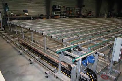


200 INFLATABLE BELT Inflatable belt drive transfer 200


201 INFLATABLE BELT LA LIBERTÉ DE CONCEVOIR 201
202 INFLATABLE BELT Inflatable belt drive transfer APPLICATIONS For workpiece carriers in accumulation Technical Data x Timing belt drive x Pulley with ball bearings x PA guiding belts x The maximum load limit is supported by ball bearings on each side x The use of compressed air lifts the belt and allows the workpiece carriers conveying Dimensions x Width A: 200 to 500 mm x Length maxi.: 6000 mm Motorisations x 230/400 V Three-Phase 50 Hz Speed in m/min (+/- 10 %): Maximum pressure: 0.8 bar The pressure regulator is not supplied in the delivery. 202
203 INFLATABLE BELT LA LIBERTÉ DE CONCEVOIR Inflatable belt drive transfer motor 5 m/min 1 pce Inflatable belt drive transfer motor 10 m/min 1 pce Inflatable belt drive transfer motor 12 m/min 1 pce Inflatable belt drive transfer motor 16 m/min 1 pce Inflatable belt drive transfer motor 18 m/min 1 pce Inflatable belt drive transfer bearing length 1 pce A 203

204 INFLATABLE BELT Inflatable belt conveyor holder APPLICATIONS Allow to easily fasten a drive unit with an inflatable belt on a frame. Caractéristiques techniques x Aluminium holder x Conveyor fastening set: Chc 8x20 Nut 6 St M5 x Frame fastening set: Chc 8x20 Nut 8 St M8 Maximum distance between axes: mm Weight: 0,11 kg 204 Inflatable belt conveyor holder 1 set


205 Applications INFLATABLE BELT 205
206 NOTES Notes 206


207 CAD LA LIBERTÉ DE CONCEVOIR Our website offers the possibility of configuring yourself on-line the transfer corresponding to your needs. Downlaod the requested solutions in CAD 2D-3D format. All CAD 2D-3D files are downloadable from our website.


208 AUTOMOTIVE INDUSTRY ELECTROMECHANICAL ELECTRICAL ENGINEERING - ELECTRONIC GB HEALTH PACKAGING Modular elements for industrialization LA LIBERTÉ DE CONCEVOIR Head-office/plants elcom SAS 1 rue Isaac Asimov ZAC de la Maladière BOURGOIN-JALLIEU, France Phone: Fax: elcom@elcom.fr elcom Deutschland GmbH Winkelsweg Langenfeld Germany Phone: Fax: info@elcom-automation.de elcom worldwilde Europe North America Asia South America Australia
Modular transfer system. PDF- Catalog Modular Transfer System
 Modular transfer system PDF- Catalog Modular Transfer System 1 Modular Transfer System TLM 1000 156, route de Lyon 38300 DOMARIN FRANCE Phone (33) 4 37 03 33 55 Fax (33) 4 37 03 33 59 September 2001 edition
MODULAR TRANSFER SYSTEM
 MODULAR TRANSFER SYSTEM & conveyors new PRODUCTS 2014 LA LIBERTÉ DE CONCEVOIR FRENCH INDUSTRIAL LEADER has brought innovating solutions to the industry. Our approach offers a complete freedom of design
NEWS Part. N /0 MINITEC NEWS
 NEWS 2009 Part. N 95.0423/0 MINITEC NEWS 2009 1 TABLE OF CONTENT INTRODUCTION CONTENTS 3 END CAP Z WITH HAMMER TAPS 3 END CAP 45X45 VA 4 ANGLE 25 GD-Z 4 ANGLE 45X90 GD-Z 5 ANGLE 90 GD-Z 5 HINGE 19 S 6
SUMMARY. V-Lock SYSTEM BASIC ELEMENTS ACTUATORS. P V-Lock GENERAL INTRODUCTION 2. P V-Lock FIXING ELEMENTS 10 SUMMARY. P V-Lock ADAPTORS 17
 SUMMARY A3 V-Lock SYSTEM P V-Lock GENERAL INTRODUCTION 2 BASIC ELEMENTS P V-Lock FIXING ELEMENTS 10 P V-Lock ADAPTORS 17 SUMMARY P PROFILES 28 P V-Lock ACCESSORIES AND SPARE PARTS 32 1 A3 GENERAL INTRODUCTION
n Measurable displacements between n Linearity: max. ± 0.05 % n Housing diameter 12.9 mm n Service life: 10 8 movements
 Potentiometric Displacement Sensor Miniature design Model 8709 Code: Delivery: Warranty: 8709 EN ex stock 24 months Application Potentiometric displacement sensors are used for direct, precise measurement
L40. Pneumatic linear slide L40
 L40 Pneumatic linear slide High stiffness and deflection resistance. Up to 30kg on the carrier. Guidance with recirculating ball-bearings. Exclusive belt drive system. Hydraulic shock-absorbers on the
aluminium profile system
 aluminium profile system 63 AME System aluminium profiles overview series profiles introduction 80x80 x80 x80/180 x Aluminium profiles are provided with longitudinal grooves which can be used in conjunction
Model No: TC10. Parts Information: Tyre Changer - Automatic
 Page 1 of 11 1 TC10.01 BODY 2 TC10.02 COLUMN 3 TC10.03 HORIZONTAL ARM ASS'Y 4 TC10.04 WASHER 5 TC10.05 RUBBER FOOT 6 TC10.06 COVER 7 TC10.07 SCREW M14x42 8 TC10.08 PRESS COVER 9 TC10.09 STOP-UP 10 TC10.10
+ A Phoenix Mecano Company. RK DuoLine 160. Degree of protection IP 40. the new industry benchmark
 RK ROSE A Phoenix Mecano Company RK DuoLine 160 Degree of protection IP 40 the new industry benchmark Greater reliability in automation......thanks to RK DuoLine 160, the new generation of spindles and
PREASSEMBLED ELEMENTS FOR LIFTING AND SLIDING DOORS
 PROFILE SYSTEM PRE-ASSEMBLED ELEMENTS FOR LIFTING AND SLIDING DOORS s r ood gni d i l s dna gni t f i l r o f s t neme l e de l bme s s a - er P PREASSEMBLED ELEMENTS FOR LIFTING AND SLIDING DOORS MINITEC
FABA. Installation Instructions. Conductor Bar System. Publication #FABA-03 3/1/04 Part Number: Copyright 2004 Electromotive Systems
 FABA Conductor Bar System Installation Instructions Publication #FABA-03 3/1/04 Part Number: 005-1062 Copyright 2004 Electromotive Systems 1S 100 Z Installation Instructions Contents: Basic Diagram - -
Clamping devices 521
 Clamping devices 521 522 Product overview Clamping devices Adjustable straps K0001 Hook clamps K0012 Goose-neck straps with long slot K0002 Page 526 Hook Clamps with collar K0013 Page 535 Equipped clamps
RPE Parallel Gripper- Electric Gripper Series
 1.14 RPE Parallel Gripper- Electric Gripper Series Failsafe Operation: Spring closed feature allows for full grip force during power off conditions. Electrically Actuated: Requires simple 24VDC pulsed
Roller Guides C-Rail Systems Linear Guide Systems Ball-Bearing Guide Bushes Ball-bush block guides Shafts Accessories for Linear Slides
 Roller Guides C-Rail Systems Linear Guide Systems Ball-Bearing Guide Bushes Ball-bush block guides Shafts Accessories for Linear Slides Application example linear systems, drives and accessories 1 2 3
mk Profile Technology
 mk Profile Technology One Construction Kit, Many Options Base Technology Profile Technology Conveyor Technology Factory Equipment Linear Motion better products, better solutions One basic technology, four
Adjustable Feet Castors Accessories for Floor Elements
 Adjustable Feet Castors Accessories for Floor Elements Products in this section Levelling Knuckle Feet Threaded spindles for infinite height adjustment Metal or plastic foot plate Knuckle Feet X Compatible
TECHNICAL INFORMATION
 TECHNICAL INFORMATION P 1 / 11 Model No. Description CONCEPT AND MAIN APPLICATIONS Specification Standard equipment TCT saw blade... 1 Rear table set (exclusively Europe, Turkey, South Africa..1 2704 This
BASIC MACHINE with X pressure bar units L 3000 with 10 t pressure force each with jig arm (C-Frame) consoles positioned on the outside of the
 consoles positioned on the outside of the") BASIC MACHINE with a torsion free machine bed which is equipped with banjo bolts to fix the machine on the ground with a linear guiding and a toothed belt driving unit for the grinding unit drive of the
BASIC MACHINE with a torsion free machine bed which is equipped with banjo bolts to fix the machine on the ground with a linear guiding and a toothed belt driving unit for the grinding unit drive of the
WM en. Zero point clamping system SPEEDY airtec 1
 SPEEDY airtec 1 GO! Maximum productivity Using the zero point clamping system SPEEDY classic you will increase your productivity to a maximum. Adjustment and checking processes are no longer necessary
Operator's manual. TruTool TKF 1500 (1A1), (1B1)
, (1B1)") Operator's manual TruTool TKF 1500 (1A1), (1B1) Table of contents 1 Safety 4 1.1 General safety information 4 1.2 Specific safety information for beveler 4 2 Description 6 2.1 Intended use 6 2.2 Technical
Operator's manual TruTool TKF 1500 (1A1), (1B1) Table of contents 1 Safety 4 1.1 General safety information 4 1.2 Specific safety information for beveler 4 2 Description 6 2.1 Intended use 6 2.2 Technical
MAGNETIC 2000 SERIES BEARINGLESS ENCODERS FOR LARGE SHAFTS
 MAGNETIC 2000 SERIES BEARINGLESS ENCODERS FOR LARGE SHAFTS Low-maintenance for large shafts Certain motors benefit from having the speed feedback sensor mounted directly on the main shaft. A bearingless
Optional keyway for location & alignment via key or Hepco dowel pins. Narrow rail with register face for convenience of spacing apart.
 The HDS2 system comprises of a versatile family of slides, flat tracks, construction beams and other components, which will meet the requirements of the most demanding applications. 2 to 7 provide an overview
 488 PARTS LIST 1 3 SCREWS FOR NO. 2 2 FLYWHEEL CAP 3 FLYWHEEL 4 END NUT FOR NO. 10 5 BALL BEARING FOR NO. 3 (1 st ) 6 BALLBEARING FOR NO. 3 (2nd) 7A CLUTCH RACE KEY 7B CLUTCH RACE 7C CLUTCH SPRING 7D 7
8 x 5 PLANER THICKNESSER OPERATING INSTRUCTIONS MODEL: W588
 8 x 5 PLANER THICKNESSER OPERATING INSTRUCTIONS MODEL: W588 Charnwood, Cedar Court, Walker Road, Bardon, Leicestershire, LE67 1TU Tel. 01530 516 926 Fax. 01530 516 929 Email; sales@charnwood.net website;
OIL AND GAS. Clamping technology for crude oil and natural gas industries
 OIL AND GAS Clamping technology for crude oil and natural gas industries CRUDE OIL AND NATURAL GAS - THE ENERGY OF TODAY RÖHM is the specialist for clamping technology with a wide product range, unrivaled
PRESENTATION. All machining Repetitive machining. The choice of a wide range of varied clamps that correspond to the individual s needs
 KOPAL PRESENTATION Vertical pressure clamping System KOPAL With neither riser block nor adjusting required, the system allows a continuous adaptation of the clamping height whilst retaining the clamping
Components made of special materials. Floor Elements for Profile St Profile KH. Fastening Elements for Profile KH
 Profile Fastening Elements for Profile Floor Elements for Profile Profile KH Fastening Elements for Profile KH Components made of special materials Products in this section Profile 8 x eel profile that
the reliable allrounders.
 Powerful solutions passionate people the reliable allrounders. the KKS series semi-automatic universal mitring circular saws > MADE IN GERMANY REQUIREMENTS MAY CHANGE WITH TIME. BUT REAL QUALITY IS ALWAYS
QIROX : The system for automated welding and cutting.
 QIROX 217 QIROX : The system for automated welding and cutting. QIROX is the new CLOOS product brand comprising all solutions for automated welding and cutting. Due to its modular design, the QIROX system
Screwdriver Function Module for the automatic Screw-Assembly
 Screwdriving Technology Automation Air Motors Air Tools Screwdriver Function Module for the automatic Screw-Assembly n wide product variety for all applications n maximum ease of integration n service
ALFRA PRESS. Made in Germany by ALFRA
 52 ALFRA PRESS Made in Germany by ALFRA 53 ALFRA PRESS Overview ALFRA PRESS AP 250 ALFRA PRESS AP 400 Page 56 Page 58 Control cabinet housing, control cabinet doors, mounting plates Control cabinet housing,
TRAKFAST REPAIR MANUAL DANGER TOOL DISASSEMBLY ALWAYS TAKE THE FOLLOWING PRECAUTIONS BEFORE ANY SERVICE OR ROUTING MAINTENANCE IS PERFORMED:
 DANGER ALWAYS TAKE THE FOLLOWING PRECAUTIONS BEFORE ANY SERVICE OR ROUTING MAINTENANCE IS PERFORMED: REMOVE FASTENERS REMOVE FUEL CELL REMOVE BATTERY REMOVE THE MAGAZINE ASSEMBLY Loosen and remove knob
The jigs and fixtures are the economical ways to produce a component in mass production system. These are special work holding and tool guiding device
 The jigs and fixtures are the economical ways to produce a component in mass production system. These are special work holding and tool guiding device Quality of the performance of a process largely influenced
KKS Circular Sawing Machines
 If Steel is Your Deal! KKS Circular Sawing www.kaltenbach.com 1 The complete KALTENBACH program for metal processing 2 www.kaltenbach.com 3 The Economical One Applications: locksmith s shop, metal construction,
OPERATING INSTRUCTIONS
 GB OPERATING INSTRUCTIONS Automatic Wedge Welding Machine Please read operating instructions carefully before use and keep for further reference. APPLICATION The is an automatic wedge welding machine for
no mm no Dividers with scriber 150 mm NEW Square wedge-shaped knife edges on the length side
 Summer Promotion valid until 30.06.2013 all quoted prices are incl. VAT for deliveries to EU countries to customers with valid VAT-no. and for deliveries in non EU member countries the VAT is not applicable
Sport-Thieme Handball Goal, 3x2 m, Free-Standing or socketed
 Assembly instructions Art.-Nr.: 201 0915 203 4502 Sport-Thieme Handball Goal, 3x2 m, Free-Standing or socketed 0218214 2018 Sport-Thieme GmbH D-38367 Grasleben Germany sport-thieme.com info @sport-thieme.com
Merloni Elettrodomestici. Technical Fitting Manual FRIDGE. Language Issue/Edition Page GB /
 GB 99-11-03/01 1-38 Index 1 CONFORMITY OF APPLIANCE 3 2 MAIN ASSEMBLY TYPES 3 2.1 Under worktop 3 2.2 Double door 10 2.3 Combined 14 2.4 Single door Fridge or single door Freezer 19 2.5 Combined free-standing
CONSTRUCTION MATERIALS
 CHANNEL GATE The model is a rectangular penstock designed for open channel installation. A resilient sealing feature is incorporated on 3 sides, (both laterals and bottom), resulting in a perfect seal
Repair Manual MWS45A-MWS50A-MWS55A MW32A-MWS36A-MWS40A. Ref Rev.D General Pump is a member of the Interpump Group
 MW/S 8 Repair Manual MWS45A-MWS50A-MWS55A MW32A-MWS36A-MWS40A General Pump is a member of the Interpump Group INDEX 1. INTRODUCTION..................................................Page 3 2. REPAIR INSTRUCTIONS...........................................Page
LENORD. +BAUER... automates motion. MiniCoder GEL 2444K Speed and position sensor with metal housing and sin/cos output
 MiniCoder GEL 2444K Speed and position sensor with metal housing and sin/cos output LENORD +BAUER... automates motion. Technical information Version 03.3 General The measuring unit comprises a sensor and
Table of Contents. B. Base Tool Changer...2 MC-6 Manual Tool Changer...2
 Table of Contents B. Base Tool Changer...2 MC-6 Manual Tool Changer...2 1. Product Overview... 2 1.1 Master Plate Assembly... 2 1.2 Tool Plate Assembly... 3 1.3 Optional Modules... 3 2. Installation...
TOOLS/PROCESSING SERVICES TOOLS + PROCESSING SERVICES
 TOOLS/PROCESSING SERVICES 7 TOOLS + PROCESSING SERVICES MINITEC PROFILE SYSTEM 583 TOOLS/PROCESSING SERVICES TOOLS s l oot TOOLS 584 MINITEC PROFILE SYSTEM BALL-HEADED KEY - Chrome plated, with handle
FEET, WHEELS, FLOOR FASTENINGS, SUPPORTS
 SYSTEM COMPONENTS FEET, WHEELS, FLOOR FASTENINGS, SUPPORTS s t r oppu S, s gn i n e t s af r oo l F, s l eehw, t e ef FEET, WHEELS, FLOOR FASTENINGS, SUPPORTS 136 MINITEC PROFILE SYSTEM BASE AND TRANSPORT
Ball rail actuator - RK DuoLine Z 80/120/160
 Ball rail actuator - RK DuoLine Z 80/120/160 A performance class with functional details that are unrivalled Cover strip 9Degree 9 of protection IP 40 Tapered lubricating nipple 9Central 9 lubricating
RYOBI. 10 in. (254 mm) TABLE SAW MODEL NO. BTS15 REPAIR SHEET
 TABLE SAW MODEL NO. BTS15 REPAIR SHEET") RYOBI 0 in. ( mm) TABLE SAW MODEL NO. BTS REPAIR SHEET FIGURE A 0 0 0 0 The model number will be found on a plate attached to the motor housing. Always mention the model number in all correspondence regarding
RYOBI 0 in. ( mm) TABLE SAW MODEL NO. BTS REPAIR SHEET FIGURE A 0 0 0 0 The model number will be found on a plate attached to the motor housing. Always mention the model number in all correspondence regarding
CamGrind L. Key data. Superproductive and perfect for batch production. A member of the United Grinding Group
 A member of the United Grinding Group Superproductive and perfect for batch production Key data The as a single-slide or two-slide machine allows you to machine shaft-type components with a length of up
Aluminium Cassette Standard
 Aluminium Cassette Standard Clearance setting 5 Fixed sidemaß Dimensions e BS N1 as t3 h10 h11 x 45 h8 h9 ±0,1 fs Ls Contact side FD with marker groove e Size Load rating Moment load rating Dimensions
CONDITIONS OF SALE AND WARRANTY
 CONDITIONS OF SALE AND WARRANTY 1. Read carefully this operator's handbook before operating our P35 corking machine. 2. F.lli Marchisio & C.Spa guarantees his P35 corking machine in case of breakages caused
TOOLS/ werkzeugtechnik
 TOOLS werkzeugtechnik EDITORIAL In October 2006, ips-werkzeugtechnik took over the punching technology segment of DE-STA-CO Europe & Co. Werkzeugtechnik, which has earned us a new strategic position on
Electrical height adjustment. ... easy & reliable. Multilift II telescope Multilift II. Synchron
 Electrical height adjustment... easy & reliable 07/2017 Multilift II telescope Multilift II Synchron Preface The Multilift lifting column has been tried-and-tested over many years in many customer applications.
Easy-To-Use Graphic Interface
 Graphical Robot Programming Teachbox for Robot W 711 The Wittmann CNC 6.2 robot control with color graphics screens allows simpler robot teaching and use than ever before. The operator simply traces out
SLIDE GATE. The MU series is used mainly in water treatment, irrigation, hydraulic works and hydro-electric power plants.
 SLIDE GATE The model is a rectangular penstock suitable for wall and thimble mounting, with a resilient sealing member applied to all 4 sides. There are two different designs, which are size dependent,
RYOBI 10 in. TABLE SAW - MODEL NO. BT3000
 FOR MITER TABLE ASSEMBLY, REFER TO FIGURE 0 RYOBI 0 in. TABLE SAW - MODEL NO. BT000 FIGURE 5: 0 in. TABLE SAW FOR BLADE GUARD ASSEMBLY, REFER TO FIGURE FOR RIP FENCE ASSEMBLY, REFER TO FIGURE FOR MOTOR
GEZE SLIDING DOOR SYSTEMS
 GEZE Perlan 140 Multi-faceted uses with individual accessories The discrete design supports every required room effect and makes the sliding door system with its accessories a guarantee for elegant and
Technical Specification
 Technical Specification Machining line English 10 / 2008 Machining line Machining line TEKNA was established in 1964 to produce efficient aluminum machining systems. The major role played by this material
Self contained servo drive CLDP Technical data sheet
 voith.com Self contained servo drive CLDP Technical data sheet Advantages + + High energy efficiency + + High dynamics + + Oil free power pack and piping are not necessary + + Sensors used provide the
High-precision inch guide units Made in Germany
 High-precision inch guide units Made in Germany cm 1 2 3 4 5 6 7 8 9 10 11 12 13 14 15 16 17 18 19 20 cm inch inch 1 2 3 4 5 6 7 8 STEINEL All you need for tools Your partner for punching and bending
RYOBI 10 IN (254 MM) TABLE SAW MODEL NO. BT REPAIR SHEET
 TABLE SAW MODEL NO. BT REPAIR SHEET") RYOBI 0 IN (2 MM) TABLE SAW MODEL NO. BT00- REPAIR SHEET 2 RYOBI 0 in. (2 mm) TABLE SAW - MODEL NO. BT00- FOR MITER TABLE ASSEMBLY, REFER TO FIGURE B FOR BLADE GUARD ASSEMBLY, REFER TO FIGURE E FOR RIP
RYOBI 0 IN (2 MM) TABLE SAW MODEL NO. BT00- REPAIR SHEET 2 RYOBI 0 in. (2 mm) TABLE SAW - MODEL NO. BT00- FOR MITER TABLE ASSEMBLY, REFER TO FIGURE B FOR BLADE GUARD ASSEMBLY, REFER TO FIGURE E FOR RIP
Operating manual. TruTool N 500 (1A1) english
 english") Operating manual TruTool N 500 (1A1) english Table of Contents 1. Safety...4 1.1 General safety information...4 1.2 Specific safety information...5 2. Description...6 2.1 Correct use...7 2.2 Technical
Operating manual TruTool N 500 (1A1) english Table of Contents 1. Safety...4 1.1 General safety information...4 1.2 Specific safety information...5 2. Description...6 2.1 Correct use...7 2.2 Technical
CORDIPAR. Universal Length Measuring Instruments. From our range. KORDT GmbH & Co. KG Preyerstraße D Eschweiler / GERMANY
 From our range External Thread Measuring Gauges from 2-996 nominal diameter Internal Thread Measuring Gauges from - 1026 nominal diameter Thread Depth Gauges to check thread depth of bores Thread Setting
ShaftGrind S. Key data. Compact and extremely versatile. A member of the UNITED GRINDING Group
 A member of the UNITED GRINDING Group Compact and extremely versatile Key data The allows you to grind shaft-type workpieces with a length of up to 650 mm. This small, versatile grinding machine guarantees
Linear Motion and Assembly Technologies Aluminum Framing /07. Die-Cast Foundation Brackets 3-10 & 3-11
 -0 Linear Motion and ssembly Technologies luminum Framing 91 500 1 /07 Section : Profile onnectors Overview One of the greatest strengths of the osch Rexroth structural aluminum framing system is the wide
PURESTREAM SYSTEM - ASSEMBLY GUIDE
 PURESTREAM SYSTEM - ASSEMBLY GUIDE VISIT OUR WEBSITE : www.cagpurification.com our installment procedure videos in the PURESTREAM Piping section. NECESSARY TOOLS FOR INSTALLATION We suggest the use of
Catalog of CLA force and torque sensors
 Catalog of CLA force and torque sensors SC-002 LC-01 LC-10 TSF-000 TSF-05 TSF-1 TSF-100 Micro-force sensor Force sensor Micro-torque sensor Torque sensor Phone +41 32 421 44 90, Fax +41 32 421 44 91, ventes@cla.ch,
CONSTRUCTION MATERIALS SERVICE CONDITIONS. Alternative alloy materials, like AISI 904L or DUPLEX stainless steel, are available if required.
 SLIDE GATE The model is a rectangular penstock suitable for wall and thimble mounting, with a resilient sealing member applied to all 4 sides. There are two different designs, which are size dependent,
Operating Instructions and Parts Manual SLT-1100 Jumbo Scissor Lift Table
 Operating Instructions and Parts Manual SLT-1100 Jumbo Scissor Lift Table JET 427 New Sanford Road LaVergne, Tennessee 37086 Part No. M-140780 Ph.: 800-274-6848 Revision B1 05/2014 www.jettools.com Copyright
PUNCHING DRILLING HEBEN LIFTING CUTTING DEBURRING
 PUNCHING DRILLING LIFTING CUTTING DEBURRING www.alfra.de E-EN E ALFRA Edge-Milling and Deburring Devices Overview KFV KFH 150 Page 7 78 2520 25100 Prism mounting L = 150 / W = 20/40 End mill Ø 45 or straight
Modular Clamping Rail System SL120 & SL080
 Original Installation and Operating Instructions Modular Clamping Rail System SL120 & SL080 Copyright ZEROCLAMP Modular Clamping Rail System Installation and Operating Instructions. These operating instructions
TC ROTARY INDEXING TABLE: RELIABILITY FOR A LIFETIME
 TC FIXED-STATION ROTARY INDEXING TABLES TC ROTARY INDEXING TABLE TC ROTARY INDEXING TABLE: RELIABILITY FOR A LIFETIME EXTENDED WARRANTY Using our rotary table control system minimises brake wear. This
Operator's manual. TruTool N 1000 (1B1) english
 english") Operator's manual TruTool N 1000 (1B1) english Table of contents 1. Safety...4 1.1 General safety information...4 1.2 Specific safety information...5 2. Description...6 2.1 Intended use...7 2.2 Technical
Operator's manual TruTool N 1000 (1B1) english Table of contents 1. Safety...4 1.1 General safety information...4 1.2 Specific safety information...5 2. Description...6 2.1 Intended use...7 2.2 Technical
SCHMIDT Flow Sensor SS Quick Guide
 SCHMIDT Flow Sensor SS 20.600 Quick Guide SCHMIDT Flow Sensor SS 20.600 Table of Contents 1 Important information... 3 2 Application range... 3 3 Assembly... 4 4 Electrical connection... 6 5 Commissioning...
VARIABLE SPEED WOOD LATHE
 MODEL MC1100B VARIABLE SPEED WOOD LATHE INSTRUCTION MANUAL Please read and fully understand the instructions in this manual before operation. Keep this manual safe for future reference. Version: 2015.02.02
» Modular clamping elements for optical or optical/tactical measurement» For high-precision edge measurements in reflected and transmitted light
 » Modular clamping elements for optical or optical/tactical measurement» For highprecision edge measurements in reflected and transmitted light» Toothed rails as workpiece stops or for fastening clamping
RYOBI 10 in. (254 mm) TABLE SAW MODEL NO. BT3100 REPAIR SHEET
 TABLE SAW MODEL NO. BT3100 REPAIR SHEET") RYOBI 0 in. (4 mm) TABLE SAW MODEL NO. BT00 REPAIR SHEET FOR MITER TABLE ASSEMBLY, REFER TO FIGURE B FOR BLADE GUARD ASSEMBLY, REFER TO FIGURE E FOR RIP FENCE ASSEMBLY, REFER TO FIGURE C FOR MOTOR ASSEMBLY,
RYOBI 0 in. (4 mm) TABLE SAW MODEL NO. BT00 REPAIR SHEET FOR MITER TABLE ASSEMBLY, REFER TO FIGURE B FOR BLADE GUARD ASSEMBLY, REFER TO FIGURE E FOR RIP FENCE ASSEMBLY, REFER TO FIGURE C FOR MOTOR ASSEMBLY,
Overview Grinding Applications
 GRINDING 14E Overview Grinding Applications SRG Workpieces High precision grinding Steady Rests Grinding diameter Ø 20-85 mm Camshafts Crankshafts Shafts Chapter 1 Fine adjustment of the grinding center
Multilift. Two-stage lifting column
 Multilift Two-stage lifting column Two-stage lifting column - Multilift Slimline design and and an unbeatable price/performance ratio Longitudinal slots 9Simple 9 connection Milled slot in the external
Screw Driven automation tables
 automation tables Precise multi-axis positioning systems play an integral part in today s semiconductor, computer peripheral, solar power, flat panel, life sciences, lab automation, biomedical and electronics
Installation of HORIZONT and HORIZONT HIGH pool enclosures
 Installation of HORIZONT and HORIZONT HIGH pool enclosures Rev. 19.10.2017 PARTS LIST Parts for rail installation: Rail screw 6 x 60 Plastic anchor 10 x 50 Rail connector Arrest wedge [R-L] Pop rivet 4
March weeks. surcharge for
 March weeks valid until 31.03.2012 all quoted prices are incl. 19% VAT for deliveries in the EU countries to customers with a valid VAT-no. and for deliveries in not EU member countries the VAT is not
PUSH-PULL-PROPS. and accessories ROBUSTA-GAUKEL GMBH MOUNTING TECHNOLOGY &CO.KG
 PUSH-PULL-PROPS and accessories MOUNTING TECHNOLOGY ROBUSTA-GAUKEL GMBH &CO.KG MOUNTING TECHNOLOGY PUSH-PULL-PROPS AND ACCESSORIES INDEX General information...................... 3 Push-pull-prop Type
Sport-Thieme. Handball Goal. Assembly instruction. 3x2 m, Free-standing with Fixed Net Brackets
 Assembly instruction Sport-Thieme Handball Goal Cat.-no.: 115 0953 2392905 239 2918 113 6500 239 2400 239 2413 3x2 m, Free-standing with Fixed Net Brackets Thanks for choosing Sport-Thieme equipment! In
CamGrind S. Key data. Small and versatile. A member of the UNITED GRINDING Group
 A member of the UNITED GRINDING Group Small and versatile Key data The allows you to grind shaft-type workpieces with a length of up to 650 mm. This small, versatile grinding machine guarantees high-precision
Table of Content. Machine Features and Functions. Specifications. Configuration and Working Principle 5. Machine Operation. Machine Adjustments
 Table of Content Safety Instructions Machine Features and Functions Specifications 2 3 4 Configuration and Working Principle 5 Machine Operation 7 Machine Adjustments 8 Machine Installation 9 Machine Remove
CS276D. CASSESE SA Zone Industrielle - F VERNEUIL L'ETANG. Telecopie : (1)
") CS276D S.A. CASSESE Z.I. - 77390 VERNEUIL L'ETANG SIREN 308 305 333 00038 S.A. au capital de 5 000 000 F Téléphone : 01 64 42 49 50 Fax 01 64 42 58 90 CASSESE SA Zone Industrielle - F 77390 VERNEUIL L'ETANG.
CS276D S.A. CASSESE Z.I. - 77390 VERNEUIL L'ETANG SIREN 308 305 333 00038 S.A. au capital de 5 000 000 F Téléphone : 01 64 42 49 50 Fax 01 64 42 58 90 CASSESE SA Zone Industrielle - F 77390 VERNEUIL L'ETANG.
Selection BASIC LINE BASIC LINE PLUS VARIO LINE SERIES TUBE LINE STEEL LINE
 PLUS 30 for cable carriers Support trays page 304 PLUS Guide channels page 305 RCC Rail Cable Carrier page 309 ECC Emergency Cable Carrier page 30 Strain relief devices page 3 Assembly profile bars page
Repair manual. Fifth-wheel coupling JSK 38/50
 Repair manual Fifth-wheel coupling JSK 38/5 ZDE 199 3 12 E 6/212 1 Foreword Table of contents Page Fifth wheel couplings are connecting parts that must comply with very high safety requirements and must
Repair Manual MK40A-MK45A-MK50A MK55A-MK60A-MK65A. Ref Rev.C General Pump is a Member of The Interpump Group
 MK Repair Manual MK40A-MK45A-MK50A MK55A-MK60A-MK65A General Pump is a Member of The Interpump Group 8 INDEX 1. INTRODUCTION..................................................Page 3 2. REPAIR INSTRUCTIONS...........................................Page
5-AXIS MACHINING SCS QUINTUS WWW. WORKHOLDINGSOLUTIONSGROUP. COM
 WORKHOLDING SOLUTIONS FOR -AXIS MACHINING SCS MC QUINTUS ONE system / MANY solutions WWW. WORKHOLDINGSOLUTIONSGROUP. COM MCCLAMPING S YSTEM for -axis machining MC + Quintus... MC Clamping System Free access
Hydraulic Clamping Systems
 Hydraulic Clamping Systems Hydraulic Swivel clamps, double action Operating pressure max. 250 bar Hydraulic swivel clamps are particularly designed for applications which require high clamping forces and
Key data. Maximum performance for large workpieces. A member of the United Grinding Group
 A member of the United Grinding Group Maximum performance for large workpieces Key data The has been specially designed for high-precision machining of large, heavy workpieces. This centerless grinding
POOL ENCLOSURES LEIA & ALVA. Assembly manual
 POOL ENCLOSURES LEIA & ALVA Assembly manual Rev. 07.2017 PARTS LIST Parts for rail installation: Rail Síncsavar screw 1 Plastic Síncsavar anchor 10 50 2 Rail Síncsavar connector 3 Arrest Síncsavar wedge
TWIN ROD CYLINDERS 6 CONTENTS
 CAD drawing data catalog is available. ACTUATORS GENERAL CATALOG TWIN ROD CYLINDERS6 CONTENTS TWIN ROD CYLINDERS 6 Features 745 Specifications/Order Codes 747 Inner Construction and Major Parts 748 Dimensions
Fifth-wheel coupling JSK 38/50
 Repair manual Fifth-wheel coupling JSK 38/5 ZDE 199 3 12 E 6/25 1 LT SK38C-3 English RevA Foreword Table of contents Page Fifth wheel couplings are connecting parts that must comply with very high safety
Key data. Flexibility for medium-sized workpieces. A member of the United Grinding Group
 A member of the United Grinding Group Flexibility for medium-sized workpieces Key data The combines precision and highest productivity in a single machine. Its modular design allows the centerless grinding
Precision made in Germany. As per DIN The heart of a system, versatile and expandable.
 1 Precision made in Germany. As per DIN 8606. The heart of a system, versatile and expandable. Main switch with auto-start protection and emergency off. Precision lathe chuck as per DIN 6386 (Ø 100mm).
RDrive 85 servo motors. User manual
 INTRODUCTION Rozum Robotics has designed its RDrive (RD) servo motors to enable precision motion control in industrial and commercial applications. This manual is intended for technicians and engineers
KTM-16/20 TECHNICAL DATA
 TECHNICAL DATA Table Diameter : 1,600mm Max. Turning Diameter : 2,000mm Max. Turning Height : 1,750mm Table Indexing Degree : 0.001mm CNC Controller : FANUC 18i-TB ** Bed The bed has symmetrical structure
RELIABLE. FULLY AUTOMATIC.
 Powerful solutions passionate people RELIABLE. FULLY AUTOMATIC. THE KKS SERIES 400 NA 451 NA 463 NA FULLY-AUTOMATIC UNIVERSAL MITRING CIRCULAR SAWS > MADE IN GERMANY REQUIREMENTS MAY CHANGE WITH TIME.
WM en. Zero point clamping system system 3000
 Zero point clamping system system 3000 unique push-on very strong automatic monitoring flush mounted SPEEDY and spigot handling without interfering contour 50kN retention force suitable for automation