POOL ENCLOSURES LEIA & ALVA. Assembly manual
|
|
|
- Avis Francis
- 5 years ago
- Views:
Transcription

1 POOL ENCLOSURES LEIA & ALVA Assembly manual Rev
2 PARTS LIST Parts for rail installation: Rail Síncsavar screw 1 Plastic Síncsavar anchor Rail Síncsavar connector 3 Arrest Síncsavar wedge 6 [R-L] x 60 4 Síncsavar Pop rivet 64 x Release Síncsavar plate [R-L] 6 Síncsavar M6 x 20 6 Screw x Síncsavar Stopper Rail Síncsavar end cap [R-L] 9 Parts for the side without rails: H-profile end cap Síncsavar 10 4,8 x 40 flat head Síncsavar screw Manual ground Síncsavar fixing Manual ground fixing - lockable Síncsavar Metal anchor Síncsavar Fixing plate for wooden deck Concrete glue Síncsavar Síncsavar Parts for end-wall installation: Solid block fixing M6 x 16 screw 4,8 X 60 flat head 4,8 X 50 turned 4,8 x 80 flat head Síncsavar Síncsavar Síncsavar Síncsavar Síncsavar screw head screw screw Outside rubber Síncsavar Mounting template Síncsavar 22 23
3 Installation manual for Leia and Alva pool enclosures General information about pool enclosures Before starting the detailed description of the installation process, we would like to provide information about pool enclosures in general. 1. Gullberg & Jansson s enclosures are delivered in pre-assembled, manually movable structural elements. This means that the installation on site only consists of rail installation, sliding the segments onto the rails, fixing the plastic longitudinal positioning elements and installing the end-walls. During installation, please always take the technical rationality and practicality into consideration. Check the functions of the structure at every phase, to allow the correction of any mistakes as soon as possible. During the manufacturing process, we simulate the final state, adjust the functions and finally test the enclosures. 2. Gullberg & Jansson s pool enclosures are manufactured according to ISO 9001/2000 standard, that among others, prescribes the use of constantly tested and calibrated measuring tools. Important: the installation of pool enclosures must be carried out with good-quality, tested tools that meet the requirements of manufacturing precision. 3. Before starting the assembly please check that the pavement provides a proper foundation for the rails. It must be suitable for the reliable installation of a pool enclosure. The receiving surface must fulfill three requirements: It must be even, waviness or height differences more than 0,5cm within 1m are not acceptable. The surface must be horizontal, with a maximum allowance of 2cm within 1m. The pavement should be sufficiently solid and minimum 10cm deep drillable and anchorable. All structural elements with individual functions - doors, end-wall openings, door locks and safety equipment, segment locks, sealings, profile end caps, handles - that are not covered in the manual are delivered ready mounted and working. The small parts needed for installation screws, anchors, rivets, structural plastic elements, keys can be found in a box that comes with the enclosure. Along with a parts list, a drawing with measurements necessary for installation and with this installation manual. Pool enclosures are manufactured using AW 6060 T6 quality custom made aluminium profiles. The surface treatment can be anodized or powder coated (any RAL colors). Fasteners and other metal sheet components are made of A2 quality stainless steel. Profile closing caps, handles and other plastic parts are made of polyamide (PE). The glazing material is polycarbonate and the rubber profiles used for fastening the panels are EPDM. The rubber seals between the segments and groove covers are silicone rubber.
4 1. Rail installation 1.1 Measure the width of the pool at its front and back Deduct the width of the pool (front: WF, back: WB) from the outside width of rails (RO) and halve the result to get the distance between the pool edge and the outside of the rails (front: DF, back DB). Mark the positions with a line. (Fig. 1.) 1.3 Connect the points on both sides with a string and mark the positions of the rails outer edges. W F = Width of the outer pool edge at the front W B = Width of the outer pool edge at the back D F = Distance between the outer edge of the pool and the outer edge of the rails at the front D B = Distance between the outer edge of the pool and outer edge of the rails at the back R O = Rail's outer width K = Diagonals L = Rail length

 and screws (Fig.")
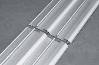
5 1.4. Join the rail sections with rail connectors (Fig. 1/1, part no.3.). Push the pins into the rail and stabilize them lightly with hammer (Fig. 1/2). Then push it together with the next rail piece without gap Place the rails to both sides of the pool and fit their outer edges to the marked line Adjust the rail positions with the help of diagonals (K). Both diagonals must be equal. (Fig.1) 1.7. Adjust the rails lengthwise by sliding them to the correct positions. Please mind that the diagonals must stay correct! 1.8. Starting on one side of the pool, fix the set rails through the pre-drilled holes with provided anchors (Fig. 1/4, part no.2) and screws (Fig. 1/5, part no.1) Before fixing the rails permanently adjust the rails horizontally too (with chocks, string or spirit level). To ensure easy gliding the whole running surface must be at the same level. 3 (1/1) (1/2)
 1")
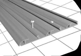
6 (1/3) 2 (1/4) 1 (1/5)

7 II. Sliding the segments onto rails and checking wind protection 2.1 Correct positioning and arrangement of segments 2.2. Lay the first segment down to the front of the rails on a plastic foam underlay Lift up the segment at the rail side and remove the underlays from there. Pull the segment carefully toward the rails and then onto the rails. Please mind that the underlay at the back should stay under the segment! 2.4. Slide the segment onto the rails and check the storm hooks by lifting. It must not be possible to lift the segment off the rails! 2.5. Check if the segment slides the full length of the rail without friction. If there is friction anywhere, please adjust the storm hooks vertically with an Allen key (Fig. 2/1) Repeat steps with all the segments in order. (2/1)

. The complete system is called Semi-intelligent arrest system. 4 (3/1) 5 (3/2) 3.1. Install the release plates (Fig.")
8 III. Installing the lengthwise positioning system (arrest system) The arrest system only works if the segments are pushed from the largest towards the smallest segment! Moving the segments the opposite direction one by one is not possible! After opening all segments, they can be pushed towards the front, but only together as a package. Description of the positioning system The lengthwise positioning of the first segment is provided by so-called hidden arrest (Fig. 3/1). All the rest of the segments are equipped with rocker lever arrest (Fig. 3/2). The complete system is called Semi-intelligent arrest system. 4 (3/1) 5 (3/2) 3.1. Install the release plates (Fig. 3/3, part no.6) of the rocker lever arrest on the segments in correct position screws no.7. The smallest segment does not have any release plates! 6 (3/3) 3.2. Move the segment to be set, starting with the largest segment, into the required lengthwise position Set the hidden arrest in closed position and lay the arrest wedge underneath (Fig.3/4-3/5, part no.4). Mark the drill-holes on the rails. 7
 on the opposite side too. 3.5.")
")

9 (3/4) (3/5) 3.4. Drill the rails at the marked spots and fix the arrest wedges with the provided pop rivets. Repeat the whole procedure on the other side. The arrest wedges must be installed to the same lengthwise positions (in-line) on the opposite side too Check if the arrest pin sits deep enough in the groove of the arrest wedge in its closed position. If the closing does not function properly, please adjust the height of the arrest pin! 3.6. The fixed arrest wedge of the first segment serves as positioning element for the second segment as well (Fig.3/6-3/7). (3/6) (3/7) 3.7. Slide the next segment under the already fixed one so that the rubber seal of the smaller segment closes to the arched profile of the bigger one. Ensure that the outer arched profiles of the segments are in the right positions. Please note! In case of deviation the overall length of the enclosure can differ at the end of the installation from the specified length on the drawing. Repeat above step on all the other segments Thanks to the semi-intelligent positioning system, after opening the hidden arrest of the first segment manually the other segments open each other automatically and all the segments can be pushed to the back of the pool together.


10 (3/8) 3.9. After installing the lengthwise positioning elements install the safety bumpers (Part no.8) close to the rail ends (Fig.3/7-3/8). When installing the stoppers, it is important to make sure that the wind hooks get caught on them, preventing the segments from running off the rails Glue the plastic rail end-caps (Part no.9) into the rail profiles with silicone or any other kind of glue. (Fig.3/9) (3/7) (3/8) (3/9)


 segments.")


11 IV. Pool enclosure with rails on only one side 4.1. Positioning the swivel wheels When sliding the segments into each other, push the swivel wheels into the guiding tracks on the H-profiles of the above (higher) segments. The swivel wheels must point towards the front of the enclosure (big segment) Closing the swivel wheel guiding tracks After linking all segments, close the guiding tracks with their end-caps (Part no.10)


12 4.3. Fixing the segments to the ground on the side without rails After positioning the segments mark the drill-holes on the ground through the fixing tabs. If the enclosure is installed on a wooden deck, please use the special mounting plates (Part no.16.) Marking the drill-holes through the fixing tabs V. End-wall installation 5.1. Fastening the solid block fixings for the middle vertical profiles The installation of the walls starts with fastening the solid block fixings (Part no.17.) with screws no.19.


13 Installation of the middle vertical profiles After installing the solid blocks, push the vertical profiles on them and fix them with screws no Temporary fixation of the glazing panels After removing the protecting foil place the panels into position and fix them temporarily with small, 15-20cm long rubber pieces (Part. no.22) two places along the arch and on the sides. 22

")


14 5.4. Installing the bottom horizontal profiles Screw the bottom profile to the middle vertical profile from below with screws no.21. In case the wall is only equipped with 100mm rubber (no flap) and there is not enough space for tightening the screws, then the segment must be pulled off from the rails and lifted. The front (or back) of the segment must be supported with something temporarily at the H-profiles. 21 After fixing the end-wall profile to the middle vertical profile, screw it to the sides with the help of screws no Sealing the wall panels with rubber Seal the polycarbonate panels with outside rubber (Part no.22.), minding that the corners must be cut in angle for aesthetic fitting. 22 After sealing the polycarbonate panels, carefully hammer the thin covers of the side vertical profiles into place with rubber or plastic hammer.
Installation of HORIZONT and HORIZONT HIGH pool enclosures
 Installation of HORIZONT and HORIZONT HIGH pool enclosures Rev. 19.10.2017 PARTS LIST Parts for rail installation: Rail screw 6 x 60 Plastic anchor 10 x 50 Rail connector Arrest wedge [R-L] Pop rivet 4
Mounting description. AQUACOMET Kft. Internet:
 Mounting description AQUACOMET Kft. Internet: www.aquacomet.hu E-mail: info@aquacomet.hu Tel/Fax: (+36 96) 314301, 517417, 328971 Mobil: (+36 30) 2046 801, 9578 470 I. Mounting of the rails 1. Measure
Installation Guide. Bi-fold Doors
 Installation Guide Bi-fold Doors Installation Guide Components box 1. 6. 2. 3. 7. 5. 4. 8. Contents 1. Fixing plugs 2. Wedge gasket 3. Bottom trolley 4. Top trolley 5. Magnetic keep (x 2 if door height
DIY GLASS BALUSTRADE AND POOL FENCING THE CHOICE IS SIMPLE
 DIY GLASS BALUSTRADE AND POOL FENCING THE CHOICE IS SIMPLE SAFE STYLISH AND AFFORDABLE FOR DIY GLASS FENCE SOLUTIONS THE CHOICE IS SIMPLE Bring your outdoor areas to life with clear views and clean lines.
The Nantucket Legacy Arbor
 ASSEMBLY INSTRUCTIONS 0. in 9 in 0. in 68 in 7 in in *Nantucket Legacy with Trim Kit Shown Above. Please read through before starting assembly. in 60 in 0 in 8 in IMPORTANT: CHECK THE INSIDE OF YOUR POSTS
IMPORTANT!!! ASSEMBLY ASSEMBLY INSTRUCTIONS. (Internal Dimensions)
") ASSEMBLY ASSEMBLY INSTRUCTIONS (Internal Dimensions) Ent Spec Edition Ltr v-0- Overall dimensions including base: 7. L x 9 W x 0 H cms 97.5" L x 7" W x 8.7" H IMPORTANT!!! Please read these instructions
ASSEMBLY ASSEMBLY INSTRUCTIONS (Internal Dimensions) Ent Spec Edition Ltr v-0- Overall dimensions including base: 7. L x 9 W x 0 H cms 97.5" L x 7" W x 8.7" H IMPORTANT!!! Please read these instructions
FEET, WHEELS, FLOOR FASTENINGS, SUPPORTS
 SYSTEM COMPONENTS FEET, WHEELS, FLOOR FASTENINGS, SUPPORTS s t r oppu S, s gn i n e t s af r oo l F, s l eehw, t e ef FEET, WHEELS, FLOOR FASTENINGS, SUPPORTS 136 MINITEC PROFILE SYSTEM BASE AND TRANSPORT
Dura-Lock Roof System
 DLR-14 Dura-Lock Roof System Assembly and Installation Instructions Read the instructions before starting the job. They explain the steps required to produce a finished product that will meet factory specifications.
*** All chrome surfaces should be cleaned using a clean damp cloth. *** No abrasive cleaning agents or materials should be used.
 Cleaning *** All chrome surfaces should be cleaned using a clean damp cloth. *** No abrasive cleaning agents or materials should be used. *** No chemical cleaners can be used on the glass use only mild
PREASSEMBLED ELEMENTS FOR LIFTING AND SLIDING DOORS
 PROFILE SYSTEM PRE-ASSEMBLED ELEMENTS FOR LIFTING AND SLIDING DOORS s r ood gni d i l s dna gni t f i l r o f s t neme l e de l bme s s a - er P PREASSEMBLED ELEMENTS FOR LIFTING AND SLIDING DOORS MINITEC
GREENHOUSE 6'x8' ASSEMBLY INSTRUCTIONS. (Internal Dimensions) Overall Dimensions (Approx.) L 193 W 200 H cms 97.5" L 76" W 78.
 Overall Dimensions (Approx.) L 193 W 200 H cms 97.5 L 76 W 78.") ASSEMBLY INSTRUCTIONS GREENHOUSE 'x8' (Internal Dimensions) Overall Dimensions (Approx.) 7. L 9 W 00 H cms 97." L 7" W 78.8" H 0 IMPORTANT You must read these instructions carefully before you start to
ASSEMBLY INSTRUCTIONS GREENHOUSE 'x8' (Internal Dimensions) Overall Dimensions (Approx.) 7. L 9 W 00 H cms 97." L 7" W 78.8" H 0 IMPORTANT You must read these instructions carefully before you start to
Dublin Stalls Installation Instructions
 Dublin Stalls Installation Instructions RAMM Horse Fencing and Stalls 13150 Airport Hwy. Swanton, OH 43558-9615 1-800-434-8456 Rev. 9/13/17 Part Identification Round Track Bracket (4) (Not Painted) Round
The Newport Arbor ASSEMBLY INSTRUCTIONS. Material You Will Need (Not Included) 4 in x 4 in x 4 ft Pressure Treated Lumber (4)
 4 in x 4 in x 4 ft Pressure Treated Lumber (4)") ASSEMBLY INSTRUCTIONS in in / in / in 0 in in in in Please read through before starting assembly. IMPORTANT: CHECK THE INSIDE OF YOUR POSTS FOR ALL MATERIALS. Check Box for These Contents In the event
ASSEMBLY INSTRUCTIONS in in / in / in 0 in in in in Please read through before starting assembly. IMPORTANT: CHECK THE INSIDE OF YOUR POSTS FOR ALL MATERIALS. Check Box for These Contents In the event
Melamine Plastic Laminate. Toilet Partition Installation Manual
 Melamine Plastic Laminate Toilet Partition Installation Manual PHONE: FAX: 1-866-317-2786 ATTENTION DO NOT MIX FASTENER PACKS EACH FASTENER PACK HAS THE NECESSARY BOLTS, BARRELS AND SCREWS TO INSTALL THE
400A 40113V, 401A 40120V, & 401AL 40120VL ALUMINUM VERTICAL 4000 LB LIFT INCLUDES SCREW LEG ASSEMBLY INSTRUCTIONS
 12/11/07 PAGE 1 OF 12 400A 40113V, 401A 40120V, & 401AL 40120VL ALUMINUM VERTICAL 4000 LB LIFT INCLUDES SCREW LEG ASSEMBLY INSTRUCTIONS Thank you for purchasing our product! *Please read these instructions
The Westchester Arbor
 A S S E M B LY I N S T R U C T I O N S 9. in 90 in. in 0 in in 0 in in Please read through before starting assembly. Check Box for These Contents In the event of missing or defective parts please call
Oceanside Outdoor Vinyl Shower Kit (3 x 3 Enclosure)
") Oceanside Outdoor Vinyl Shower Kit ( x Enclosure) A B ASSEMBLY GUIDE REQUIRED FOR INSTALLATION (A) Zippity Post Extension for In-Ground Installation (Sold as 4-Packs) (B) Zippity Galvanized Steel Surface
Oceanside Outdoor Vinyl Shower Kit ( x Enclosure) A B ASSEMBLY GUIDE REQUIRED FOR INSTALLATION (A) Zippity Post Extension for In-Ground Installation (Sold as 4-Packs) (B) Zippity Galvanized Steel Surface
Greenhouse Assembly Instructions
 Greenhouse Assembly Instructions Our Help Line provides support and advice to customers of Summer Garden Buildings after ordering. For advice before you buy you can phone us free 7 days a week on 0800
Shetland Stalls Installation Instructions
 Shetland Stalls Installation Instructions RAMM Horse Fencing and Stalls 13150 Airport Hwy. Swanton, OH 43558-9615 1-800-434-8456 Rev. 1/9/18 Before you start Kit can accommodate up to 12 wide stall front
Oxford Stalls Installation Instructions
 Oxford Stalls Installation Instructions RAMM Horse Fencing and Stalls 13150 Airport Hwy. Swanton, OH 43558-9615 1-800-434-8456 Rev. 8/15/17 Before You Start Typical stall sizes are 10 x 10, 12 x 12 or
Allora ALCOVE ENCLOSURE INSTALLATION BEFORE INSTALLATION CHECK THAT YOUR ALLORA SHOWER ENCLOSURE SYSTEM IS UNDAMAGED
 Allora ALCOVE ENCLOSURE INSTALLATION BEFORE INSTALLATION CHECK THAT YOUR ALLORA SHOWER ENCLOSURE SYSTEM IS UNDAMAGED ALCOVE SHOWER Your shower can be installed to open Left hand or Right hand by rotating
Franklin Mills Stackable Movable Lateral Instructions
 Franklin Mills Stackable Movable Lateral Instructions Table of Contents: Table of contents...1 Tools Required...2 Stationary Shelving Assembly...3-7 Mobile Shelving Assembly...8-16 Rail Assembly...8-11
Cardo DOOR & RETURN SHOWER ENCLOSURE INSTALLATION PLEASE READ THESE INSTRUCTIONS CAREFULLY.
 Cardo DOOR & RETURN SHOWER ENCLOSURE INSTALLATION PLEASE READ THESE INSTRUCTIONS CAREFULLY. IT IS RECOMMENDED TO USE A TRAINED SHOWER INSTALLER FOR THIS SHOWER TO OBTAIN THE BEST INSTALLATION. D Square
 SUPREME WALL GARDEN ASSEMBLY INSTRUCTIONS 24/08/16 www.hallsgreenhouses.com Please refer to website for the most up to date instructions. SAFETY WARNING 1. Always wear protective glasses, shoes, gloves
Phone # La Jolla Doors. Block Frame Installation Manual Aluminum Frame with either Vinyl or Aluminum Panels
 Phone # 800-440-8785 www.lajolladoors.com La Jolla Doors Block Frame Installation Manual Aluminum Frame with either Vinyl or Aluminum Panels Thank you for choosing La Jolla Doors In this manual you will
INSTALLATION INSTRUCTIONS
 Tools required for the installation. A. Core Drill 87mm Drill bit B. Tape measure C. Spirit Level D. Marking pen E. Caulking gun F. Cutting Pliers G. Cordless Drill and Philips head bit, 5mm Drill bit.
INSTALLATION INSTRUCTIONS IMPERVIA SLIDING PATIO DOOR WITH FINS
 2008 Pella Corporation Part Number: 803V0101 INSTALLATION INSTRUCTIONS IMPERVIA SLIDING PATIO DOOR WITH FINS Installation Instructions for Typical Wood Frame Construction. These instructions were developed
Two Panel Frameless Bypass Door
 INSTALLATION INSTRUCTIONS Two Frameless Bypass Door Series 00 Please Record Model Number From Carton Label Here Please read these instructions carefully to familiarize yourself with the required tools,
CONTENTS TOOL LIST U P S I D E I N N O V A T I O N S, L L C RAMP AND STEP SYSTEM ASSEMBLY INSTRUCTIONS. Revised: June 2013
 U P S I D E I N N O V A T I O N S, L L C RAMP AND STEP SYSTEM ASSEMBLY INSTRUCTIONS TOOL LIST Required Tools: - Reciprocating Saw with Metal Cutting Blade - Drill - 7/16 Drill Bit for Metal Drilling -
VisioGlide 100 System W4F Four doors 2 fixed, 2 sliding
 Balcony Systems 2011 Visio Glide W4-F Curved Sliding Doors 4 doors: 2 fixed, and 2 sliding Installation guide 1. Insert silicone into the two bottom corners before closing the frame. 1 2. Connect top and
Installation - Sub Cills
 Installation - Sub Cills Fitting of Subcill Drainage paths through the sub-cill can be seen on the illustration alongside so care must be taken to ensure they are not obstructed and that screw fixings
INSTALLATION INSTRUCTIONS
 Tools required for the installation. A. Core Drill 87mm Drill bit B. Tape measure C. Spirit Level D. Marking pen E. Caulking gun F. Cutting Pliers G. Cordless Drill and Philips head bit, 5mm Drill bit.
Stainless Steel 95C34 Series
 Stainless Steel 95C34 Series Toilet Partition Installation Manual PHONE: FAX: 866-317-2786 ATTENTION DO NOT MIX FASTENER PACKS EACH FASTENER PACK HAS THE NECESSARY BOLTS, BARRELS AND SCREWS TO INSTALL
ALLORA SWING PANEL INSTALLATION INSTRUCTIONS
 ALLORA SWING PANEL INSTALLATION INSTRUCTIONS Before Installation Please check that your Allora Swing Panel is undamaged SEQUENCE OF INSTALLATION These instructions are also available from the Athena website:
US RACK, Inc Falcon Drive, Madera, CA
 US RACK, Inc. - 2850 Falcon Drive, Madera, CA 93637-559-661-3050 INSTRUCTIONS for MOTORCYCLE RACK with Cradling Wheel Chocks WARNING: Do NOT attempt to install or use this rack without following all instructions.
#4 Phillips Driver Bit 1/8, 4mm, 5.5mm & 8mm (5/16 ) Allen Wrench. Safety Glasses
 Allen Wrench. Safety Glasses") ATLANTIS RAIL Contact Information: Atlantis Rail Systems 70 Armstrong Road 3900 Civic Center Drive Plymouth, MA 02360 North Las Vegas, NV 89030 (800) 541-6829 or (508) 732-9191 (508) 732-9798 www.atlantisrail.com
ATLANTIS RAIL Contact Information: Atlantis Rail Systems 70 Armstrong Road 3900 Civic Center Drive Plymouth, MA 02360 North Las Vegas, NV 89030 (800) 541-6829 or (508) 732-9191 (508) 732-9798 www.atlantisrail.com
Gardman Lean-to Greenhouse Assembly Instructions
 Page 1 Gardman Lean-to Greenhouse Assembly Instructions Our Help Line provides support and advice to customers of Summer Garden Buildings after ordering. For advice before you buy you can phone us free
ASS 70 FD folding / sliding door. Installation Guide
 ASS 70 FD folding / sliding door Installation Guide IMPORTANT! These doors should be fitted by competent and trained installers. Please read these instructions thoroughly before beginning the installation.
USER S MANUAL. Horizontal inclinometer system Model TES-AN-25H
 USER S MANUAL Horizontal inclinometer system Model TES-AN-25H Doc. # WI 6002.82 Rev. 01 Printed May 2011 System description & method statement for installing ABS casing (Model TES-AN-25H horizontal inclinometer
EDGE-, COVER-, SLIDEAND SEALING PROFILES
 PROFILE SYSTEM EDGE-, COVER-, SLIDE- AND SEALING PROFILES s e l i f o r P gn i l aes dna - ed i l S, - r evoc, - egde EDGE-, COVER-, SLIDEAND SEALING PROFILES These profiles are used for groove covering
Portofino Installation Guide
 vjul16 (for 17 or 24 mm Surface Wall Profiles) DO NOT ASSEMBLE WITHOUT FULLY READING THESE INSTRUCTIONS Page 2 Thank you for purchasing this Portofino shower enclosure. Please study these instructions
Installation Instructions
 by Plato Woodwork Installation Instructions Plato Woodwork, Inc. 200 Third Street SW P.O. Box 98 Plato, MN 55370 www.platowoodwork.com 800.328.5924 SECTION GUIDE GETTING STARTED PAGE # Installation Methods...
INSTALLATION GUIDE DUOFUSE GARDEN GATE
 Installation guide nr.: Version Publication date MOVO- 0008 V2 1/04/2015 INSTALLATION GUIDE DUOFUSE GARDEN GATE The Duofuse wood composite garden gate is much more durable than a wooden gate, and correct
Cabonyx Installation Manual
 Cabonyx Installation Manual Content Deck-Nyx and Plan-Nyx Installation Page 1 Flooring Products Page 1 Accessories Page 1 Installation Tools Page 2 Preparing Sub-structure Page 2 Installation Page 4 Cautions
BY ALIEN TECHNOLOGIES CORP
 BY ALIEN TECHNOLOGIES CORP Assembly Instructions TopLift Pros YOU MAY ALSO REVIEW OUR ASSEMBLY VIDEO, PLAY AND PAUSE AT YOUR CONVENIENCE. JUST VISIT US AT WWW.TOPLIFTPROS.COM AND GO TO Customer Support
The Devonshire Arbor 85 in
 ASSEMBLY INSTRUCTIONS in in in in in Please read through before starting assembly.. in IMPORTANT: CHECK THE INSIDE OF YOUR POSTS FOR ALL MATERIALS. Check Box for These Contents In the event of missing
935 RODA VINESSE NEED INSTALLATION HELP? DOUBLE ROLLERS FRAMELESS DOOR INSTALLATION INSTRUCTIONS QCI XX/XX/XXXX. Call BASCO ( )
") INSTALLATION INSTRUCTIONS 935 RODA DOUBLE ROLLERS FRAMELESS DOOR NEED INSTALLATION HELP? Call 1-800-45-BASCO (452-2726) Monday - Friday VINESSE QCI0286 1 XX/XX/XXXX 935 Roda Parts List With double rollers
INSTALLATION INSTRUCTIONS 935 RODA DOUBLE ROLLERS FRAMELESS DOOR NEED INSTALLATION HELP? Call 1-800-45-BASCO (452-2726) Monday - Friday VINESSE QCI0286 1 XX/XX/XXXX 935 Roda Parts List With double rollers
Assembly Instructions
 Selling Station Assembly Instructions View from above without top A B C D Rounded finished corners on A & D Square unfinished 3-sides on B & C Selling Station Components (2) 2' x 6' Side s Have a channel
40mm Thermoclick. Type II Class 1 Clear Satin Anodize - 201R1 (Mid Grade Commercial)
") http://www.sundancesupply.com 40mm Thermoclick Type II Class 1 Clear Satin Anodize - 201R1 (Mid Grade Commercial) U-Profile 12' Lengths $39 Out System offers a complete set of extrusions and accessories
http://www.sundancesupply.com 40mm Thermoclick Type II Class 1 Clear Satin Anodize - 201R1 (Mid Grade Commercial) U-Profile 12' Lengths $39 Out System offers a complete set of extrusions and accessories
Ultra Fast Delivery SGL Toilet Cubicle Pack Fitting Instructions
 Ultra Fast Delivery SGL Toilet Cubicle Pack Fitting Instructions This instructional booklet should be read in full prior to undertaking any work. If in doubt please call Commercial Washrooms on 01202 650900,
I n s t a l l a t i o n I n s t r u c t i o n s S E N T I N E L S E R I E S 1 50 SLIDING GLASS DOORS
 I n s t a l l a t i o n I n s t r u c t i o n s S E N T I N E L S E R I E S 1 50 SLIDING GLASS DOORS Page 2-9: Installation Instructions, Figures 1, 2, & 3 Page 10-12: Figures A-1, A-2, & A-3: Installation
10 x 10 Flat Top Two Tone Pergola
 0 x 0 Flat Top Two Tone Pergola Models: Bordeaux ASSEMBLY GUIDE OPTIONAL ACCESSORIES Arch Kit System ( Arches) Privacy Fence Panel System ( Panels & Middle Post) Bolt Down Bracket Kit ( for Pergola) Ver.0-00
INSTALLATION INSTRUCTIONS
 PARTS LIST ITEM PART DESCRIPTION QTY 73-A 503F 9MM 50G 5A 50E 505S 50H Connector Bracket Door Stops Support Bar Panel Glass Bracket Wall Mount Bracket Rollers Center Guide Recessed Finger Pull Fixed Panel
a.k.a. casegoods instructions
 a.k.a. casegoods instructions a a.k.a. workwall installation IMPORTANT NOTES Failure to install product according to installation instruction will result in loss of warranty. Tools required for assembly
Display Shelving Installation Instructions
 Display Shelving Installation Instructions Top Rail (R-T) Back (BE) (R-C) Splicer Rail (R-S) 78 H to 120 H only Uprite (U) Uprite End Trim (UET) Shelf Back (BE) Base End Trim (BET) (R-C) 96 H to 120 H
10x10 Trellis Pergola
 0x0 Trellis Pergola ASSEMBLY GUIDE Ver.0-7 Table of Contents PAGE Introduction & Overview...................................................... Pergola Materials Overview..............................................................
Piazzola Pergola Awning Manufacturing and installation guide
 Piazzola Pergola Awning Manufacturing and installation guide Date Changes Page General information Maximum and minimum width Width Projection 150 to 349 cm 350 to 500 cm From 200 to 250 cm X From 251 to
Outdoor equipment. Barrier posts. Stainless steel. Barrier elements. Barrier poles. Outdoor equipment - pages
 - pages 215-228 Bicycle stands / lean-on hoops Laundry drying stands Tree guards Litter bins Planters 215 Bicycle rack Sturdy and space-saving due to alternating high and low racks. Racks can be bolted
TD10A INSTALLATION GUIDE TUB DOOR
 Thank you for choosing Valley Acrylic Products. This installation manual provides general information on the installation of our products. BEFORE YOU BEGIN Prior to installation, examine all boxes and
Track Rack. * Track Racks are not lockable
 The Track Rack s unique staggered, sliding hook design creates the greatest parking efficiency while still providing easy access to any particular bike. When adding or removing a bike to the rack, simply
IMPORTANT: WILL NOT FIT COUNTRYMAN MODELS
 Part #1410-0102-07 2 3 1 IMPORTANT: WILL NOT FIT COUNTRYMAN MODELS Apply masking tape around the bottom grille opening and across the bottom of the upper facto ry grille.. Open the hood and remove the
1200 SERIES 2 PANEL DOOR rev.1 DETAILED INSTALLATION INTRUCTIONS
 1200 SERIES 2 PANEL DOOR 10.2013 rev.1 DETAILED INSTALLATION INTRUCTIONS GENERAL: Door elevations shown in these instructions are as viewed from the outside. X denotes the active or moving panel(s). O
ATLANTIS RAIL Contact Information
 ATLANTIS RAIL Contact Information Customer Service (800) 541-6829 (508) 732-9191 Spectrum System Installation Instructions Atlantis Rail s Spectrum System is an easy to install, universal cable railing
XL JOINERY LTD LA PORTE VISTA MODULAR 3 ASSEMBLY INSTRUCTIONS
 XL JOINERY LTD LA PORTE VISTA MODULAR 3 2090mm High x 4687mm Wide ASSEMBLY INSTRUCTIONS READ AND UNDERSTAND THESE INSTRUCTIONS FULLY PRIOR TO STARTING INSTALLATION. IT IS STRONGLY RECOMMENDED THAT A COMPETENT
Mount to the Wall INSTALLATION MANUAL
 Mount to the Wall 15 Locate the Wooden Studs This step applies to wooden stud wall installation only. Determine and mark the exact locations of two stud centers on the wall. Wooden studs should be spaced
LAWN AND GARDEN GREENHOUSE
 MODELS# OG0AL8-BKE OGAL-8 OGrow Walk-in ' x 8' LAWN AND GARDEN GREENHOUSE With Heavy Duty Aluminium Frame MANUAL VERSION # Grow r! e h t e g To Let's Thank you for purchasing the OGROW greenhouse Follow
LEGENDS RETRACTABLE DOOR SCREENS
 LEGENDS RETRACTABLE DOOR SCREENS MAGNETIC LATCHING DESIGN SYSTEM 42 I N S T A L L A T I O N I N S T R U C T I O N S 1 MOUNTING OPTIONS Recess : Mount the Screen Cassette using Recess Mounting Clips Recess
INFINITE RANGE - CENTRE FOLDING DOOR
 INFINITE RANGE - CENTRE FOLDING DOOR CENTRE FOLDING DOOR ONLY ( RECESS) Please read these instructions before installing, as incorrect fitting will invalidate the guarantee-carry out each stage before
Frameless Fixed Panel Slider
 INSTALLATION INSTRUCTIONS Frameless Fixed Panel Slider QCI-5279 SINGLE ROLLER WITH ANTI-JUMP DOUBLE ROLLERS QCI5279 Rev Page Certified 08/09/6 Tools: To install your New Shower Enclosure, you may need
The Nantucket Legacy Arbor
 SSEMLY INSTRUTIONS The Nantucket Legacy rbor Please read through before starting assembly. IMPORTNT: HEK THE INSIDE OF YOUR POSTS FOR LL MTERILS. heck ox for These ontents In. the Keystone event of missing
LEGENDS RETRACTABLE DOOR SCREENS
 I N S T A L L A T I O N I N S T R U C T I O N S 1 MOUNTING OPTIONS Recess : Mount the Screen Cassette using Recess Mounting Clips Recess within the door jamb area. Recess installations are the most typically
Laminate Cabinet Installation Instructions
 Laminate Cabinet Installation Instructions www.easygaragestorage.com/installation How To Use These Instructions Thank you for your purchase! Please read each step of this manual thoroughly to ensure proper
S H E D A S S E M B L Y I N S T R U C T I O N S
 T I T A N R A N G E S H E D A S S E M B L Y I N S T R U C T I O N S 6 X 4ft = 190 x 150 cm 6 X 6ft = 190 x 190 cm 6 X 8ft = 190 x 255 cm COMPONENT LIST Component illustrations are given as a visual guide
TOOLS REQUIRED Metal Wood Wood and Metal Screws. #16 Drill #12-24 Tap. 1/8 Drill
 DEVICES COVERED IN THIS DOCUMENT: 4700S Surface Vertical Rod Device 4700SF Fire Exit Surface Vertical Rod Device TOOLS REQUIRED Metal Wood Wood and Metal Screws Sex Bolts #7 Drill ¼ -20 Tap #16 Drill #12-24
PRIME SHOWER ENCLOSURE INSTALLATION INSTRUCTIONS
 PRIME SHOWER ENCLOSURE INSTALLATION INSTRUCTIONS IMPORTANT DreamLine reserves the right to alter, modify or redesign products at any time without prior notice. For the latest up-to-date technical drawings,
Installation Instructions
 Supafold Slide Aside System Three Fold Room Divider Installation Instructions Distinctive Doors Ltd Supafold Slide Aside Internal Folding System IMPORTANT: Before proceeding with the installation, and
W1610 1/2 10 X 16 SOLARIUM ASSEMBLY INSTRUCTIONS Assembly by more than one person is suggested.
 adlonco@hotmail.com W60 / 0 X 6 SOLARIUM ASSEMBLY INSTRUCTIONS Assembly by more than one person is suggested. Requires 96 clearance at the wall Base Dimensions 90 x 8, Largest Dimensions 90 x (see pg.3)
E N G L I S H GARDEN SHED. Assembly Instructions. Suitable for Models WITH VARYING DEPTHS
 GARDEN SHED Assembly Instructions Suitable for Models 6' Wide 8' Wide 0' Wide WITH VARYING DEPTHS GI0003 November 0 INSTALLATION ADVICE It's Not That Difficult! The construction of your shed isn't as complicated
ICU TRACK SLIDING DOOR
 Interior View 0 Installation Instructions Tools Required: Screwdrivers Small Straight (Flat Blade) - for Terminal Block wiring # Phillips (Crosspoint) - for various #8, #0, and # screws Wrenches / Sockets
Deauville Installation Guide
 vjul16 (for 17 or 24 mm Surface Wall Profiles) DO NOT ASSEMBLE WITHOUT FULLY READING THESE INSTRUCTIONS Page 2 Thank you for purchasing this Deauville shower enclosure. Please study these instructions
INSTALLATION INSTRUCTIONS
 INSTALLATION INSTRUCTIONS SOLID PHENOLIC TOILET PARTITIONS 1080 DuraLineSeries Class-A Fire Rated Includes Institutional Hardware Option.67 IMPORTANT: Storage and Handling Information on last page. Review
ICU TRACKLESS SLIDING DOOR
 Interior View 0 Installation Instructions Tools Required: Screwdrivers Small Straight (Flat Blade) - for Terminal Block wiring # Phillips (Crosspoint) - for various #8, #0, and #4 screws Wrenches / Sockets
INSTALLATION INSTRUCTIONS
 INSTALLATION INSTRUCTIONS BUILDERS CHOICE FRAMED Bypass Door Model: L0516 (Tub Height), L0517 (Shower Height) Rev. 09.20.13 INSTALLATION NOTES: Unpack your unit carefully and inspect for freight damage.
INSTALLATION INSTRUCTIONS
 INSTALLATION INSTRUCTIONS TOOLS REQUIRED Rechargeable, variable speed drill 3/8 diameter drill bit 3 Robertson bits #0, #1 and #2 Slot screwdriver Non marring hammer with 1 head Level Caulk or sealant
CYCL E STAT IO N. High Capacity
 CYCL E STAT IO N High Capacity The Dero Cycle Station provides high-capacity, covered bike parking for bicycle commuters. With a high roof and open platform, the Dero Cycle Station allows bike corrals,
Side Light Frame Pack Assembly Instructions
 Please read this complete set of assembly instructions before starting the installation and only when you understand the construction method start to follow the step by step guide. IDENTIFY THE PACK CONTENTS
SLIDING TUB / SHOWER ENCLOSURE WITH STATIONARY 90º PANEL
 SLIDING TUB / SHOWER ENCLOSURE WITH STATIONARY 0º PANEL This instruction sheet applies to the following units. C, C7, C7, C77, C, C7 This instruction sheet also applies to the following units. VTE / VSE
Installation Instructions for Vista Air Vertically Folding Walls
 Installation Instructions for Vista Air Vertically Folding Walls Use these instructions in conjunction with your shop drawings to see the specifics that are particular to the model you are installing.
Installation manual. For setting in concrete/on base plates - Panel height 1830
 1 Aluminium fencing and drive-in gates Installation manual For setting in concrete/on base plates - Panel height 1830 Aluclos system components: U10 Connecting U-bracket 1900 mm CL18/CL18.XL Half-height
CertainTeed INSTALLATION GUIDE SIMTEK FENCE PRODUCTS. Fence Installation Guide 3', 4' & 6' High
 CertainTeed INSTALLATION GUIDE SIMTEK FENCE PRODUCTS Fence Installation Guide 3', 4' & 6' High INSTALLATION GUIDE These instructions are designed to assist both professional installers and do-it-yourselfers
SMART SYSTEMS VISOGLIDE+ INSTALLTION GUIDE
 SMART SYSTEMS VISOGLIDE+ INSTALLTION GUIDE Please read guide before beginning any installation. Instructions/Guides Keys & Handle Screw Covers Interlock Covers Anti-Lift & Rubber Stops Anti-Lift for Slim
Thank you for your order
 Installation Guide Thank you for your order Ph: 09-9133110 Fax: 09-9133113 5 Smales Road. East Tamaki, Manukau PO Box 58031 Greenmount, Manukau 2013 AUCKLAND // WELLINGTON // CHRISTCHURCH www.bathroomdirect.co.nz
Organisational Kitchen Fittings Kitchen Cabinet Accessories
 Kitchen waste bin systems Single waste bin, capacity 1 litres Carcase width: Min. 400 mm For door mounting: For left and right hand use Installation: Screw fixing to side panel Housing: Steel, plastic
FIXED PANEL SLIDER QCI5241
 INSTALLATION INSTRUCTIONS FIXED PANEL SLIDER QCI5241 FRAMELESS PANEL / DOOR / PANEL FRAMELESS DOOR / PANEL QCI5241 REV. 0 Page 1 Certified 06/16/2016 Parts List *Quantities may vary QCI5241 REV. 0 Page
200A FLB VERTICAL 22113V LIFT W/CHAIN DRIVE WINCH
 PG. 1 OF 11 PORTA-DOCK, INC. 200A FLB VERTICAL 22113V LIFT W/CHAIN DRIVE WINCH STEP 1. Separate and group like parts and fasteners together. Locate the winch side member with the longer upright tube and
EASY-IN POOL STEP SYSTEM NE132
 EASY-IN POOL STEP SYSTEM NE132 This instruction manual features multiple guides for the step unit components. 7939 EASY POOL STEP (NE113) FOR USE WITH: EASY-IN POOL STEP (NE126) 6492 PARTS & HARDWARE FOR
LAWN AND GARDEN GREENHOUSE
 MODEL# OGAL-66 OGrow Walk-in 6' x ' LAWN AND GARDEN GREENHOUSE With Heavy Duty Aluminium Frame Let'sGrow Together! Thank you for purchasing the OGROW greenhouse Follow the assembly and safety instructions
Installation Guide Simplicity Alfresco. V1.9 Lu070318
 0333 305 5272 www.canoports.co.uk Installation Guide Simplicity Alfresco V1.9 Lu070318 Tools Required Below is a list of tools that you will require to install your the Simplicity Alfresco System. Cordless
Under Seat Storage Drawer Installation Instructions
 Under Seat Storage Drawer Installation Instructions Parts List: 1) Drawer Assembly 8) Self Tapping Screws 1) Instructions 1) Template Tools Needed: Drill and/or Bit Driver Tape Measure Jigsaw or metal
S H E D A S S E M B L Y I N S T R U C T I O N S
 T I T A N R A N G E S H E D A S S E M B L Y I N S T R U C T I O N S 8 X 10 ft Approx = 2550 x 3140 cm COMPONENT LIST Component illustrations are given as a visual guide only and are not in proportion PART