Hubble GOTO Installation Instruction (1.3, 04/30/2014)
|
|
|
- Arline Davis
- 5 years ago
- Views:
Transcription
1 Hubble GOTO Installation Instruction (1.3, 04/30/2014) 1. Preparation Tools required AZ GOTO Drive Parts List ALT GOTO Drive Parts List The Azimuth motor drive installation The ALT motor drive installation Preparation Before starting your installation, please make sure that you have all the required tools and all the parts in the Parts Lists. This manual only cover the mechanical installation of the GOTO system. For the installation, wiring and configuration of SiTech controller, please refer to SiTech Quick Start Guide for Hubble Optics ULs. 1.1 Tools required Hand drill with 4mm and 10mm bits (Not required if the system is GOTO ready) Metal saw and round steel file (Not required if the system is GOTO ready) Philips screw drivers Tape measure Crescent wrench Hex key set 1.2 AZ GOTO Drive Parts List AZ geared motor assembly with mounting plate 2 tension springs 10mm spacer 3 AZ spoke arms AZ encoder mounting plate One brass AZ encoder housing Mounting screws AZ quick release clamp 1.3 ALT GOTO Drive Parts List ALT geared motor assembly with mounting plate 2 meter long SS strand cable 1 tension spring (the strongest one) Grooved ALT bearing Teflon pads (2) Mounting screw ALT quick release clamp ALT extension module There are total of 3 tension springs. The strongest one is for the ALT axis, while the two weaker ones are for the AZ bearing axis. Page 1

2 2. The Azimuth motor drive installation 1. Remove the secondary cage and all truss tubes from the OTA. Then carefully remove the mirror from the mirror box and place the mirror in a safe place. 2. Lift the mirror box off the rocker and rest it on the side. Please do not rest the mirror box on the ALT bearing surface; you may damage the laminate surface. 3. This step is only needed for the system without the GOTO ready option. You need to drill 3 holes, a 4mm and a 16.5mm through holes and a M6 threaded hole, as shown in the following drawings. For the 16.5mm hole, please drill a small 4mm diameter pilot hole first; then enlarge it with the 10mm pit and finally use a round steel file to further enlarge it to the required 16.5mm diameter. For the 25mm diameter half circle at the bottom of the rocker frame, it will be much easier to use a metal saw to cut a triangle open first, and then use a steel file to round it to the required half circle. To avoid causing any damage to the AZ bearing, you must remove the AZ bearing from the Rocker before doing the drilling! Figure 1: Drilling positions Page 2


3 Figure 2: UL14 and UL16 drilling positions Please note the center of the half circle is 72 mm from the centerline for UL14 and UL16, and 160mm for UL18 and UL20. Page 3


4 Figure 3: UL14 and UL16 drilling positions Figure 4: UL18 and UL20 drilling positions Page 4


5 Figure 5: UL18 and UL20 drilling positions Figure 6: UL18 and UL20 drilling positions 4. Install the 1 diameter brass AZ encoder housing into the center holes of the three stainless steel Azimuth spoke arms as shown below using a M6 x10 hex screw. Do not tighten them too tightly yet. Page 5


6 Figure 7: AZ Spoke Arms 5. Install the three stainless steel Azimuth spoke arms to the inner AZ bearing ring with three M6 screws (You may have to drill and tap three roughly evenly spaced M6 holes on the inner AZ bearing ring if they are not pre-drilled and tapped). Please make sure the encoder housing is precisely placed at the AZ bearing center by making sure the scale readings on all three AZ spoke arms are exactly the same at the edge of the AZ inner bearing. Tighten three M6 screws and the center screw to lock the encoder housing to the AZ arms tightly. You can install the AZ spoke arms in the same three holes used by the three footers, and use the same wing nuts to lock the spoke arms. Page 6

7 Figure 8: AZ Spoke Arm Installation 6. Install the AZ encoder arm assembly by carefully inserting the encoder shaft into the center hole of the brass encoder housing. Adjust the depth so the threaded shank of the encoder does not, but just about to touch the housing; a mm gap is fine. Tighten the Nylon setscrew on side of the brass housing onto the shaft. Page 7

8 Figure 9: AZ encoder Arm Installation Page 8

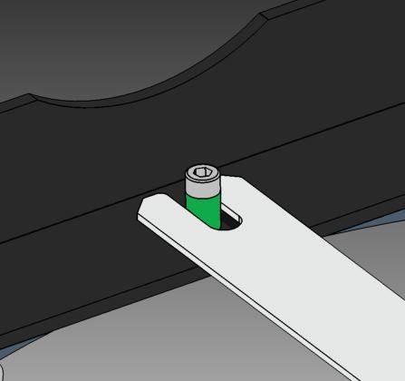
9 7. Center the AZ encoder arm anchor slot with the anchor hole on the Rocker frame. Then install the provided M5 screw into the anchor hole and tighten firmly. You may want to wrap a few layer of tape around the head of anchor screw if the anchor slot is a bit larger than the screw head. Make sure the slot is snuggly fit with screw head. 8. Now install the AZ motor assembly. First, center the installation hole on the AZ motor assembly plate with the installation hole on the rocker frame. Then, insert the provided10mm diameter spacer into the AZ motor assembly installation hole. Figure 10: Center the installation holes Page 9


10 Figure 11: Insert the provided 10mm diameter spacer Then place a larger spacer on top of the 10mm spacer on the AZ motor assembly plate. Figure 12: Installation of the AZ motor assembly Finally insert a hex head screw into the installation hole, and tighten it with a wrench. You may need to add more spacers to make sure the screw does not touch the AZ inner bearing ring. Page 10


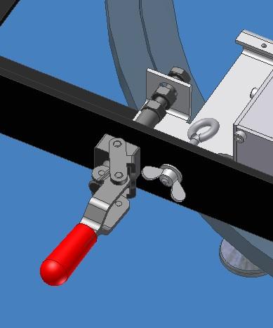
11 9. Install the AZ quick release clamp. Page 11


12 10. Insert the provided M4 eyebolt into the hole next to the AZ quick release clamp. Then add a spacer on the outside of the eyebolt and install a wing nut on top of it. Page 12
13 Page 13

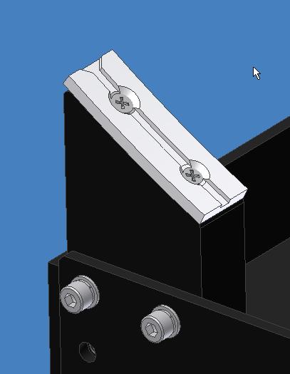
14 Then install the 12mm spring as shown above, and adjust the wing nut to apply the tension. You may want to hook two springs for more tension. 11. Install all AZ motor and encoder cables as shown in Appendix A of SiTech GOTO Quick Start Guide 3. The ALT motor drive installation 1. Make sure to complete the AZ motor installation first before doing the ALT motor installation 2. Replace 2 of the regular Teflon pads with 2 new grooved Teflon pads. Make sure the top of the crosshead screws are lower than the bottom of the grooves. Page 14
15 Page 15


16 3. Remove the upper section of the ALT bearing. Drill and tap a M4 hole on the front tip of the left altitude bearing as shown below. Page 16


17 Page 17


18 4. Place the mirror box on the side and remove the lower left ALT bearing from the mirror box 5. Install the ALT GOTO extension module to the lower left ALT bearing with one M6 cross head screw. You will need to use a socket head screw and nut if the hole on the bearing is not tapped. Center another hole with the corresponding hole on the bearing, but leave it open. 6. Re-install the ALT bearing back to the mirror box. Please note that you will need to remove or replace one of the spacer with a thinner spacer to compensate the thickness of the extension block. Page 18


19 7. Re-install the ALT upper bearing section back to the mirror box Page 19

20 8. Remove two of screws on the rocker as shown below, and install the ALT motor assembly in these two holes. Page 20

. Make sure the SS cable is restricted in the grooves on the Teflon pads. 11.")
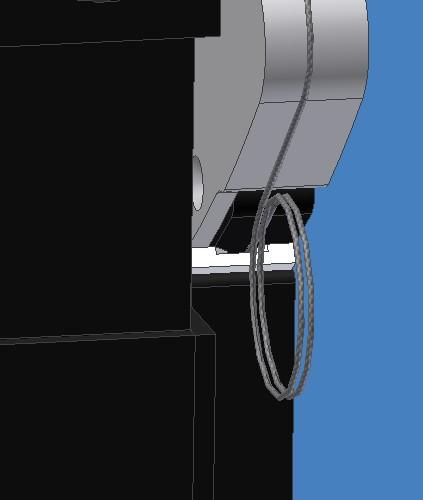
21 9. Place the SS cable along grooved ALT Teflon pads; make sure that the SS cable rests in the groove on the Teflon pads. You can use some small pieces of scorch tape to keep the cable in place. But do not put the tape on the Teflon pads! You may not be able to completely remove the tape! 10. Carefully place the mirror box back on the rocker, and tighten the mirror box to rocker with the provided Nylon strips to avoid any mirror box movement (You must un-tighten these strips before operating the GOTO). Make sure the SS cable is restricted in the grooves on the Teflon pads. 11. Lock the upper end loop of the SS cable with the screw as shown in the following picture. Page 21


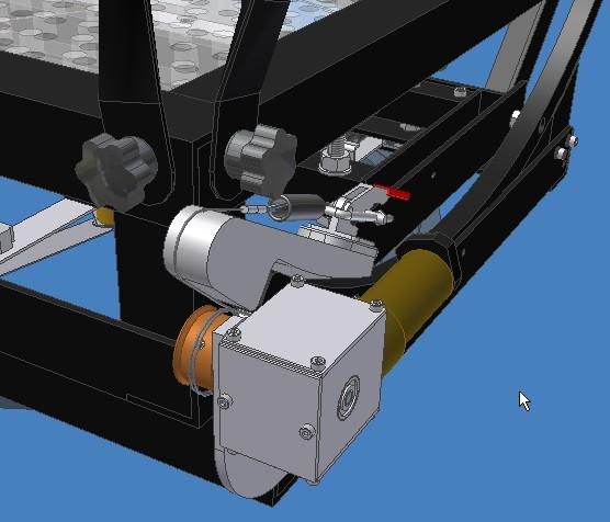
22 12. Hold the SS cable and wrap it around the AZ drive roller twice, and then hook the SS cable to the end of the tension spring. Make sure to release the clamp when doing so, and then push the clamp back to the "engaged" position. You can adjust the end nuts on the clamp "U" bracket to adjust the tension when needed. Make sure the tension is no more and no less, just enough to avoid the SS cable slipping from the brass drive roller. Page 22
23 Page 23


24 13. ALT Encoder Installation Install the 1 diameter brass AZ encoder housing into the one of center holes of the ALT encoder holder bracket as shown below using a M6 x10 hex screw. Page 24

25 A: for UL14 B: for UL16 C: for UL18 D: for UL20 Recommended positions; however you may use different position for your scope to make sure that the encoder is indeed centered. Page 25


26 Install the ALT encoder holder to the mirror box with the M6 knob screws Page 26

27 Install the Azm encoder&arm assembly by carefully inserting the encoder shaft into the center hole of the brass encoder housing. Adjust the depth so the threaded shank of the encoder does not touch the housing. Tighten the Nylon setscrew on side of the brass housing onto the shaft. Adjust the ALT encoder bracket to position to make sure it is centered at the ALT bearing axis: Once the encoder is centered, then set the mirror box to zenith, 45 degree, and then 90 degree, you should see the pivoting screw hole at the bottom remain at the same location at the ALT encoder bracket Page 27


28 Mirror Box at Zenith Mirror Box at 45 degree Page 28

29 Mirror Box at 90 degree 14. Follow the UL SiTech Quick Start Guide to connect the motor and encoder wiring and configure the SiTech controller Page 29
30 WARNING! Your scope should be well balanced before GOTO operation. Otherwise, the motor will get into blinking mode (manual mode) and the gearbox may be damaged Page 30
Code Product Qty 1 Top Vertex 3 2 Hot End Housing 1 3 Bottom Vertex 3 4 Print Platform Lock 3 5 End Stop Holder 3 6 Filament Feeder Motor Bracket 1 7
 List of Parts Code Product Qty 1 680mm Extrusion 3 2 Power Supply 1 3 240mm Extrusion 9 4 42mm Nema 17 Stepper Motor 3 5 Slider-Hotend Connecting Rod 6 6 48mm Nema 17 Stepper Motor 1 7 Linear Rail with
Astro-Physics Inc. 400QMD Lubrication/Maintenance Guide
 Astro-Physics Inc. 400QMD Lubrication/Maintenance Guide The following guidelines should be followed to lubricate the three main parts of the 400QMD mount. The QMD stands for Quartz Micro-Drive controller.
GlideRite Retractable Cover System For Hot Spot Spas (SE & SLX only)
") List of Contents Quantity Description 12 #10 x 1 ½ Flat Head Phillips Screw (see pg. 2) 2 #10 x ½ Pan Head Phillips Screw (see pg. 2) 8 ¼ x 2 ½ Lag Bolt (see pg. 2) 7 ¼ 20 x 5 / 8 Hex Head Bolt (see pg.
List of Contents Quantity Description 12 #10 x 1 ½ Flat Head Phillips Screw (see pg. 2) 2 #10 x ½ Pan Head Phillips Screw (see pg. 2) 8 ¼ x 2 ½ Lag Bolt (see pg. 2) 7 ¼ 20 x 5 / 8 Hex Head Bolt (see pg.
GlideRite Retractable Cover System For HotSpring & Tiger River Spas (except Classic & pre-2000 Landmark Spas)
") List of Contents Quantity Description 12 #10 x 1 ½ Flat Head Phillips Screw (see pg. 2) 2 #10 x ½ Pan Head Phillips Screw (see pg. 2) 8 ¼ x 2 ½ Lag Bolt (see pg. 2) 7 ¼ 20 x 5 / 8 Hex Head Bolt (see pg.
List of Contents Quantity Description 12 #10 x 1 ½ Flat Head Phillips Screw (see pg. 2) 2 #10 x ½ Pan Head Phillips Screw (see pg. 2) 8 ¼ x 2 ½ Lag Bolt (see pg. 2) 7 ¼ 20 x 5 / 8 Hex Head Bolt (see pg.
Installation Instruction
 Tools Needed for Assembly Stud finder (for wood stud wall) Pencil Mark Electric drill Wood Stud Wall Installation Step 1. Locate the Wood Studs Installation Instruction Drill bit (for wood stud wall) Masonry
TIRE RACK INSTALLATION INSTRUCTIONS Dodge Sprinter
 Aluminess Products Inc 9402 Wheatlands Ct. #A Santee, CA 92071 619-449-9930 TIRE RACK INSTALLATION INSTRUCTIONS 07-11 Dodge Sprinter Please read before beginning Stainless steel hardware may bind together
3,500/4,500lb. Vertical Cable Feighner Lift
 3,500/4,500lb. Vertical Cable Feighner Lift CAUTION - PUT SAFETY FIRST 1. Before attempting to install or operate this lift, study and fully understand the proper operating procedures and safety precautions
Hubble Optics Ultra Portable UP 12 Dobsonian instruction manual
 Hubble Optics Ultra Portable UP 12 Dobsonian instruction manual Draft: 1.0 12-27-2016 Please read these instructions thoroughly before beginning assembly and subsequent use of the telescope. 1. Unpacking...2
Assembly Instructions 10 X 10 Aluminum Roof Support
 Assembly Instructions 10 X 10 Aluminum Roof Support Aluminum Roof Support Bolt Package 16-5/16 X 2 ¼ SS Bolt 24-5/16 X 1 SS Bolt 40-5/16 SS Nylon Lock Nuts 16-5/16 SS Flat Washers 28-4 ½ Wood Screws 36-1
Hubble Optics Ultra Light UL 16 Dobsonian instruction manual
 Hubble Optics Ultra Light UL 6 Dobsonian instruction manual REV:.. 03-0-202 Please read these instructions thoroughly before beginning assembly and subsequent use of the telescope..unpacking... 2 2. Assembly...
M2 Assembly. M2 Sub-Assemblies mm Belt Sub-Assembly mm Belt Sub-Assembly Spider Sub-Assembly... 4
 M2 Assembly Table of Contents M2 Sub-Assemblies... 3 630mm Belt Sub-Assembly... 3 702mm Belt Sub-Assembly... 3 Spider Sub-Assembly... 4 Idler Bolt Sub-Assembly... 8 Y Motor Sub-Assembly... 9 X Motor Sub-Assembly...
3D PRINTER. Pack 11. Anything you can imagine, you can make! 3D technology is now available for you at home! BUILD YOUR OWN
 BUILD YOUR OWN Pack 11 Anything you can imagine, you can make! 3D PRINTER Compatible with Windows 7 & 8 Mac OS X 3D technology is now available for you at home! BUILD YOUR OWN 3D PRINTER CONTENTS PACK
400GTO Lubrication Guide
 400GTO Lubrication Guide Lubrication Guidelines for the following equatorial mounting: 400GTO Servo with GTOCP2 or CP3 Controller For other 400 models please review other postings as they become available.
BABY WOLF LOOM. Assembly Instructions for Knocked-Down Looms
 BABY WOLF LOOM Assembly Instructions for Knocked-Down Looms BEFORE YOU BEGIN Please read through the directions before beginning to assemble your loom. Unpack the loom parts carefully. Do not throw away
Side Mount INSTRUCTION BOOKLET #C122 BED STYLE: PARK CITY
 Side Mount BED STYLE: PARK CITY INSTRUCTION BOOKLET #C1 WARNING! ALL MURPHY/WALLBED SYSTEMS CONTAIN STORED ENERGY. FAILURE TO USE AND FOLLOW THESE INSTRUCTIONS DURING THE INSTALLATION PROCESS COULD RESULT
Installing the Partridge RA Extension on Losmandy G11
 Installing the Partridge RA Extension on Losmandy G11 Michael Herman July 20, 2015 Tools: 3/16 inch hex key (allen wrench) [If desired for DEC indicator ring friction improvement: flat screwdriver, and
SPARE PARTS LIST MODEL NO. LB1200F PAGE 1 ITEM PART NO. DESCRIPTION QTY NOTE
 PAGE 1 001 JM21000018 HEX.SOCKET HEAD SCREW M5X12 4 002 JM21000019 SPRING WASHER 5 4 003 JM21000020 FLAT WASHER 5 4 004 JM21000021 UP COVER COMPLETE 1 005 JM21000025 MICRO SWITCH FIX PANEL A 1 006 JM21000026
Original Gallery System
 GAllery System Art Displays Original Gallery System a Gallery System product Here s everything you need to know to get started with your Gallery System Art Hanging System GS getting started To install
Assembly Instructions 10 X 10 Aluminum Frame Building
 Assembly Instructions 10 X 10 Aluminum Frame Building 27 97 9 8 47 36 74 52 10 10 X 10 Square Building W/ Dome Includes: The Steel Entry Door with a Dead Bolt Lock assembly and Aluminum Door Frame. Metal
WILDING WALLBEDS INSTALLATION INSTRUCTION Side Mount
 WILDING WALLBEDS INSTALLATION INSTRUCTION Side Mount For Wallbed models: Do-It-Yourself Insturction booklet C92 WARNING! ALL MURPHY/WALLBED SYSTEMS CONTAIN STORED ENERGY. FAILURE TO USE AND FOLLOW THESE
ABM International, Inc.
 ABM International, Inc. Lightning Stitch required 1 1.0: Parts List head and motor assembly (Qty. 1) Reel stand (Qty. 1) Needle bar frame clamp (Qty. 1) Motor drive (Qty. 1) 2 Cable harness with bracket
General Features. Low Profile. The SMART BOXX stands only 1.5 off of the bed of your truck so cargo space is maximized
 General Features Low Profile. The SMART BOXX stands only 1.5 off of the bed of your truck so cargo space is maximized Two Sizes Short Box :74 L X 47 W X 7 T and Long Box 92 L X 47 W X 7 T All Aluminium
INSTRUCTION BOOKLET #C20
 INSTRUCTION BOOKLET #C0 WARNING! ALL MURPHY/WALLBED SYSTEMS CONTAIN STORED ENERGY. FAILURE TO USE AND FOLLOW THESE INSTRUCTIONS DURING THE INSTALLATION PROCESS COULD RESULT IN SEVERE PERSONAL INJURY TO
ABM International, Inc. Navigator Assembly Manual
 ABM International, Inc. 1 1.0: Parts List Tablet (Qty. 1) Tablet mount (Qty. 1) NOTE: Mount may appear and operate different then image below Control Box (Qty. 1) Motor Power Supply (Qty. 1) 2 X-axis motor
1503 Follow Spot Yoke, Source Four LED
 1503 Follow Spot Yoke, Source Four LED Rev 1.0 2016 City Theatrical, Inc. Getting Started with the City Theatrical Follow Spot Yoke for source four LED Congratulations on the purchase of your City Theatrical
 INSTRUCTION BOOKLET #C10 Watch step by step installation instructions at: https://www.wallbedsbywilding.com/wallbed-installation-studio-series/ WARNING! ALL MURPHY/WALLBED SYSTEMS CONTAIN STORED ENERGY.
INSTRUCTION BOOKLET #C21. For Wallbed models: KING SIZE
 For Wallbed models: KING SIZE INSTRUCTION BOOKLET #C1 WARNING! ALL MURPHY/WALLBED SYSTEMS CONTAIN STORED ENERGY. FAILURE TO USE AND FOLLOW THESE INSTRUCTIONS DURING THE INSTALLATION PROCESS COULD RESULT
INSTALLATION INSTRUCTIONS
 INSTALLATION INSTRUCTIONS SOLID PHENOLIC TOILET PARTITIONS 1080 DuraLineSeries Class-A Fire Rated Includes Institutional Hardware Option.67 IMPORTANT: Storage and Handling Information on last page. Review
RYOBI. 10 in. (254 mm) TABLE SAW MODEL NO. BTS15 REPAIR SHEET
 TABLE SAW MODEL NO. BTS15 REPAIR SHEET") RYOBI 0 in. ( mm) TABLE SAW MODEL NO. BTS REPAIR SHEET FIGURE A 0 0 0 0 The model number will be found on a plate attached to the motor housing. Always mention the model number in all correspondence regarding
RYOBI 0 in. ( mm) TABLE SAW MODEL NO. BTS REPAIR SHEET FIGURE A 0 0 0 0 The model number will be found on a plate attached to the motor housing. Always mention the model number in all correspondence regarding
1) Place the reactor stand on a sturdy bench with the bottom plate facing toward the front.
 Place the reactor stand on a sturdy bench with the bottom plate facing toward the front.") Assembly Instructions for ChemRxnHub Reactor Systems 1) Place the reactor stand on a sturdy bench with the bottom plate facing toward the front. Loosen knobs on the right and left using 2 hands of the
Assembly Instructions for ChemRxnHub Reactor Systems 1) Place the reactor stand on a sturdy bench with the bottom plate facing toward the front. Loosen knobs on the right and left using 2 hands of the
MM540 Installation Instructions IMPORTANT SAFETY INSTRUCTIONS - SAVE THESE INSTRUCTIONS
 MM50 Installation Instructions IMPORTANT SAFETY INSTRUCTIONS - SAVE THESE INSTRUCTIONS Please read this entire manual before you begin. Do not unpack any contents until you verify all requirements on PAGE.
MM340 Installation Instructions IMPORTANT SAFETY INSTRUCTIONS - SAVE THESE INSTRUCTIONS
 MM30 Installation Instructions IMPORTANT SAFETY INSTRUCTIONS - SAVE THESE INSTRUCTIONS Please read this entire manual before you begin. Do not unpack any contents until you verify all requirements on PAGE.
Gared Pro-S Portable Backstop
 Models: 9616 & 9618 Installation, Operation and Maintenance Instructions Please read all instructions before attempting installation or operation of these units SAVE THESE INSTRUCTIONS FOR FUTURE USE PUBLICATION
MantelMount. TM1A Installation Instructions IMPORTANT SAFETY INSTRUCTIONS - SAVE THESE INSTRUCTIONS
 MantelMount TMA Installation Instructions IMPORTANT SAFETY INSTRUCTIONS - SAVE THESE INSTRUCTIONS TM Thank you for choosing the MantelMount television wall mount. Please read this entire manual before
FLIP TARP SINGLE & DOUBLE UNDERBODY TRAILERS
 1-800-248-7717 1002 N. 15th Street, Middlesboro, KY 40965 FLIP TARP SINGLE & DOUBLE UNDERBODY TRAILERS INSTALLATION INSTRUCTIONS Congratulations on your purchase of a Mountain Flip Tarp Trailer system.
https://www.wallbedsbywilding.com/wallbed-installation-studio-series/
 For Wallbed models: KING SIZE INSTRUCTION BOOKLET #C1 Watch step by step installation instructions at: https://www.wallbedsbywilding.com/wallbed-installation-studio-series/ WARNING! ALL MURPHY/WALLBED
N. 15th Street, Middlesboro, KY FLIP TARP DUMP BODY INSTALLATION INSTRUCTIONS
 1-800-248-7717 1002 N. 15th Street, Middlesboro, KY 40965 FLIP TARP DUMP BODY INSTALLATION INSTRUCTIONS Congratulations on your purchase of a Mountain Flip Tarp Dump Body tarping system. With tarping systems
 For Wallbed models: KING SIZE INSTRUCTION BOOKLET #C1 Watch step by step installation instructions at: https://www.wallbedsbywilding.com/wallbed-installation-studio-series/ WARNING! ALL MURPHY/WALLBED
Nancy s Knit Knacks LLC 4 Yard Option Upgrade Kit Assembly Instructions and User Manual
 Nancy s Knit Knacks LLC 4 Yard Option Upgrade Kit Assembly Instructions and User Manual Thank you for purchasing our 4 Yard Option (4YO) Upgrade Kit. To install this upgrade you are simply going to assemble
 INSTRUCTION BOOKLET #C0 Watch step by step installation instructions at: https://www.wallbedsbywilding.com/wallbed-installation-studio-series/ WARNING! ALL MURPHY/WALLBED SYSTEMS CONTAIN STORED ENERGY.
400A 40113V, 401A 40120V, & 401AL 40120VL ALUMINUM VERTICAL 4000 LB LIFT INCLUDES SCREW LEG ASSEMBLY INSTRUCTIONS
 12/11/07 PAGE 1 OF 12 400A 40113V, 401A 40120V, & 401AL 40120VL ALUMINUM VERTICAL 4000 LB LIFT INCLUDES SCREW LEG ASSEMBLY INSTRUCTIONS Thank you for purchasing our product! *Please read these instructions
INSTALLATION INSTRUCTIONS
 INSTALLATION INSTRUCTIONS HIGH PRESSUE LAMINATE (HPL) TOILET PARTITIONS 1030 TrimLineSeries 1040 DesignerSeries Includes continuous hardware option.65. IMPORTANT: Storage and Handling Information on last
INSTALLATION INSTRUCTIONS FOR SL-LB MANUAL LIFT BARRIER GATE ARMS
 INSTALLATION INSTRUCTIONS FOR SL-LB MANUAL LIFT BARRIER GATE ARMS Questions? Call 520-780-9751 or visit our website at: www.barriergatearm.com YOUR SL-LB MANUAL LIFT BARRIER GATE ARM WILL ARRIVE WITH WEIGHT
Spring Loaded All Season Roll-Up Doors
 Spring Loaded All Season Roll-Up Doors STAND-OFF MOUNTING METHOD INSTALLATION INSTRUCTIONS READ THIS FIRST Carefully examine the crate(s) for damage before opening. If the carton is damaged, immediately
3/8-16 x 3/4 cap screw. 3/8-16 hex nut for above screws. 1/4-20 x 3/4 socket cap screw. 3/16 short arm hex key (not to scale)
") Super Slab Roller 24, 30 and 36 models Worktable Assembly Directions P.O. Box 89 Cheney, WA 99004 USA 509.235.9200/800.23.7896 Fax: 509.235.9203 www.northstarequipment.com Revised September, 2006. All
Super Slab Roller 24, 30 and 36 models Worktable Assembly Directions P.O. Box 89 Cheney, WA 99004 USA 509.235.9200/800.23.7896 Fax: 509.235.9203 www.northstarequipment.com Revised September, 2006. All
The Mind Project s Iris 1 Robotic Arm. Assembly instructions Step 1
 The Mind Project s Iris 1 Robotic Arm Assembly instructions Step 1 Packing list Below you will find pictures and descriptions of each part. It may be helpful to take each piece out of the bag and place
MOTORIZED STANDARD SHADE WITH CABLES Installation Instructions
 Tools Needed Drill Measuring Tape Pencil 2 Level Plumb Line ¼ Masonry Drill Bit Hammer Linesmans Pliers Cable Cutters Phillips & Flat-Head Screw Driver 11/32 Socket or Open End Wrench 5/32 Allen Wrench
INSTRUCTION BOOKLET #34. For Wallbed models: KING SIZE SIERRA WITH STORAGE HEADBOARD
 For Wallbed models: KING SIZE SIERRA WITH STORAGE HEADBOARD INSTRUCTION BOOKLET #34 WARNING! ALL MURPHY/WALLBED SYSTEMS CONTAIN STORED ENERGY. FAILURE TO USE AND FOLLOW THESE INSTRUCTIONS DURING THE INSTALLATION
Side Winder R o u t e r L i f t.
 Woodpeckers PRECISION WOODWORKING TOOLS Side Winder R o u t e r L i f t. INSTALLATION INSTRUCTIONS The wrench handle must be pointing left in order to fully insert or remove it. Lift Wrench Once fully
Preference Collection 5580 Treatment Console INSTALLATION GUIDE
 Preference Collection 5580 Treatment Console INSTALLATION GUIDE 0 WARNING Failure to install the 5580 as described in this installation guide may cause the unit to collapse, resulting in serious injury
Warnings. Description. Prior to Installation Tools Needed
 Warnings Failure to act in accordance with the following may result in death or personal injury. The JT Strong Arm Stabilizer System is intended to eliminate chassis movement in travel trailers and fifth
ATLANTIS RAIL Contact Information
 ATLANTIS RAIL Contact Information Customer Service (800) 541-6829 (508) 732-9191 Spectrum System Installation Instructions Atlantis Rail s Spectrum System is an easy to install, universal cable railing
Equilibrium. Conference Table. Installation Instruction. Revision B 11/07/16
 Equilibrium Conference Table Installation Instruction Revision B 11/07/16 Equilibrium End User Agreement Enwork Equilibrium table bases must be installed directly onto a four inch minimum thickness concrete
LEG CURL IP-S1315 INSTALLATION INSTRUCTIONS
 LEG CURL IP-S35 INSTALLATION INSTRUCTIONS Copyright 2009. Star Trac by Unisen, Inc. All rights reserved, including those to reproduce this book or parts thereof in any form without first obtaining written
11 6 Round Building Assembly Instructions
 11 6 Round Building Assembly Instructions 11 6 Round Building Hardware List 1. Pro Rib Brite White 36 Wide X 68 Long (Siding Steel) 11 2. Top Wall Wheel Ring 3 3. Base Ring 3 4. 1 ½ X 68 Aluminum Tubes
PFW 6851 Display Wall Mount, Turn & Tilt 80 kg INSTALLATION INSTRUCTIONS
 Display Wall Mount, Turn & Tilt 80 kg INSTALLATION INSTRUCTIONS 9531-007-Z00-01 Table of Contents Warning Statements 2 Parts List 3 Installation Tools 3 Wood Stud Installation 5 Concrete Surface Installation
Page 1. SureMotion Quick-Start Guide: LARSACC_QS 1st Edition - Revision A 03/15/16. Standard Steel Bolt/Screw Torque Specifications
 R K C T I Repair Kit Product Compatibility Repair Kit # Linear Actuator Assembly # LARSACC-013 LARSACC-014 LARSD2-08T12BP2C (12-in travel) LARSD2-08T24BP2C (24-in travel) C P I R K 1 ea Ball Screw with
INSTALLATION INSTRUCTIONS FOR FRONT CASTING DECK RAIL Ranger
 INSTALLATION INSTRUCTIONS FOR FRONT CASTING DECK RAIL Ranger TOOLS REQUIRED FOR INSTALLATION: Drill motor, (1) 5/16 inch drill bit, (1) 13/64 drill bit, (1) 3/16 inch hex wrench (1) 3/32 inch hex wrench.
Note: Parts without part numbers are for reference only and cannot be purchased individually.
 Parts Ordering Replacement Parts To order parts or reach our service department, call 1-800-274-6848 Monday through Friday (see our website for business hours, www.waltermeier.com). Having the Model Number
Metroboard Pulley Replacement Procedure
 Metroboard Pulley Replacement Procedure 1) Remove the two transmission cover screws (1/8 allen driver). Then remove the transmission cover. Note there is a split lock washer and flat washer as well, so
IDR assembly instructions:
 IDR assembly instructions: Required Tools: 2 X 12mm Open End Wrench 14mm open end wrench #2 Phillips Head Screw Driver (Drill with adjustable torque clutch recommended) 8mm nut driver (Supplied in IDR-AK)
DC3210. Recommended Closer Size
 Installation Instructions For Non-Hold Open or A Hold Open Arm Option DC3200 Series Multi-Sized thru 6 Regular Arm Universal Door Closers Parallel Arm Jamb Mount See pages 2&3 See pages 4&5 See pages 6&7
SERVICE PARTS LIST PAGE 1 OF 6 BASE ASSEMBLY SPECIFY CATALOG NO. AND SERIAL NO. WHEN ORDERING PARTS 12" SLIDING COMPOUND MITER SAW
 PAGE 1 OF 6 BASE ASSEMBLY 00 0 CATALOG NO. EXAMPLE: SPECIFY CATALOG NO. AND NO. WHEN ORDERING PARTS 6955-20 1 02-80-0050 Thrust Bearing (1) 2 05-80-0510 M5 x 12mm Flat Head T-20 Screw (5) 3 05-81-0135
MODEL 83 Pail Handler
 MORSE MFG. CO., INC. 727 West Manlius Street P.O. Box 518 East Syracuse, NY 13057-0518 Phone: 315-437-8475 Fax: 315-437-1029 Email: service@morsemfgco.com Website: www.morsemfgco.com COPYRIGHT 2005 MORSE
Special Z-Axis Ballscrew Replacement
 To replace Z-axis ballscrew without removing X-axis components When rebuilding an OmniTurn slide, all the precision components are replaced. The tooling plate and saddle are removed to gain access to the
PRS Retro Z-Axis Installation
 PRS Retro Z-Axis Installation Page -1- PRS Retro Z-Axis Installation This document is a guide to installing the PRS Retro Z-axis on early ShopBot models. It describes installation for PR models with PK299
This instruction manual is an in-depth look and explanation of how to assemble and install the Murphy Bed properly and efficiently.
 This instruction manual is an in-depth look and explanation of how to assemble and install the Murphy Bed properly and efficiently. Don t be put off by the size of the instruction manual as the large diagrams
Pantry IMPORTANT NOTE Carefully remove all the parts from the carton and put them individually on a soft cloth to prevent scratches or oth
 88 5076 691 Pantry IMPORTANT NOTE Carefully remove all the parts from the carton and put them individually on a soft cloth to prevent scratches or other damages occurring to the parts. We have taken great
RBP-1215B-RX DODGE RAM QUAD CAB RX3
 RBP-1215B-RX3 2002-2017 DODGE RAM 15-3500 QUAD CAB RX3 Passenger side RX-3 Side Step Drill Template Passenger side rear Modular Bracket (6) L Support Brackets Driver side rear Modular Bracket Driver side
Depending on the size you ordered you will have either 5 Foot sections which will build the 10 Foot frame or 6 Foot sections which will build the 12
 XL Quilting Frame 1 Depending on the size you ordered you will have either 5 Foot sections which will build the 10 Foot frame or 6 Foot sections which will build the 12 Foot frame Printed 2 June 2014 Updated
F i t t i n g t h e N e w L a n d i n g G e a r t o Y o u r S k y J i b V 1
 F i t t i n g t h e N e w L a n d i n g G e a r t o Y o u r S k y J i b V 1 1 P a r t s L i s t : S t a n d a r d L a n d i n g G e a r U p g r a d e Product Code Parts + Spares Product Code Parts + Spares
SM-RAZOR-F-M/L/XL. Strong Low Profile Fixed Mount for Ultra-Thin Flat-Panel TVs INSTALLATION MANUAL
 SM-RAZOR-F-M/L/XL Strong Low Profile Fixed Mount for Ultra-Thin Flat-Panel TVs INSTALLATION MANUAL WARNINGS: Installation of this product should be done by a qualified professional. Do not begin installation
INSTALLATION INSTRUCTIONS
 INSTALLATION INSTRUCTIONS For Wallbed models: Do-It-Yourself BOOKLET #C90 WARNING! ALL MURPY/WALLBED SYSTEMS CONTAIN STORED ENERGY. FAILURE TO USE AND FOLLOW THESE INSTRUCTIONS DURING THE INSTALLATION
TABLE OF CONTENTS REQUIRED TOOLS
 TABLE OF CONTENTS SECTION SECTION TITLE PAGE NO. 1 2 3 4 5 Assembling Mounting Structure Installing Bicycle Supports Mounting Rack to Wall Adding Sections Customizing Rack Configuration REQUIRED TOOLS
Installation Manual for Metal Toilet Partitions Standard Series
 For Video instructions http://www.hadrian-inc.com/tech-data/installation/toilet-partitions.aspx P a g e 1 Table of Contents Page General Notes and Tools Required 3 STEP 1: Establish Floor Bracket Locations
ELECTRIC TOOL PARTS LIST
 Hitachi Power Tools LIST E936 ELECTRIC TOOL PARTS LIST COMPOUND SAW Model 2004 4 20 (E1) 1 2 3 23 24 7 8 9 10 6 5 4 15 11 16 12 13 12 14 18 25 26 27 28 29 30 19 17 1 9 11 16 21 624 20 22 39 40 41 42 35
25-200H. 12 Planer / Jointer. with Helical Cutterhead. Parts List.
 25-200H 12 Planer / Jointer with Helical Cutterhead 4001824 Parts List www.rikontools.com CABINET ASSEMBLY PARTS EXPLOSION & PARTS LIST KEY NO. DESCRIPTION KEY NO. DESCRIPTION 1 Pan Head Screw M6x12 P25-200H-1
Interactive Monitor Arm
 Interactive Monitor Arm Tools Required -5mm Allen wrench -Phillips screwdriver -Plastic mallet There are two ways to attach a Monitor Arm to a Full Frame; with a Beam, or with a Post Mount. Both methods
Projector Ceiling Mount
 INSTALLATION MANUAL Projector Ceiling Mount PID:3010 PID:5466 20kg (44lbs) RATED CAUTION: DO NOT EXCEED RATED LISTED WEIGHT. SERIOUS INJURY OR PROPERTY DAMAGE MAY OCCUR! ISSUED: FEB. 2013 NOTE: Read the
M4 Foot Operated Underpinner Instruction Manual
 M4 Foot Operated Underpinner Instruction Manual M4 Walker Rd, Bardon Hill, Coalville, Leicestershire LE67 1TU, England Tel. +44 (0)130 1692, Fax +44 (0)130 16929 e mail sales@framerscorner.co.uk M4 Underpinner
Rudder Pedal Kit. Assembly Manual. V1.0 July 2010.
 Rudder Pedal Kit Assembly Manual V1.0 July 2010. Introduction: Thank you for your purchase of our Boeing 737 Rudder Pedal Kit. many years of faithful service from our product. We hope you will have Our
Mounting a BalanceBox 400 to a brick wall
 Unpack the BalanceBox 400 and remove the Wall frame cover and its bag of screws. Slide the cover out at the top. NOTE: the cover is NOT included with the BalanceBox 400H LOCK SCREW HOLE MOBILE STAND MOUNTING
AndyMark DART 12.
 AndyMark DART 12 Part Number Description QTY These Parts Are Pre-Assembled by AndyMark am-0031 Bearing, 3/16"ID (R3) 1 am-0209 Bearing, 3/8"ID 1614ZZ 2 am-1028 Screw, #10-32x3/8 Pan Head Philips 8 am-1121
WALLBED Assembly Instructions
 WALLBED Assembly Instructions 1 Congratulations and a Big Thank You for your purchase of a Wallbed Gallery Murphy Bed! We sincerely appreciate your business! First a few words of advice and caution: 1.
ELECTRIC TOOL CORPORATION
 Cat. No. -0 / Hex Demolition Hammer Cat. No. 0-0 Spline Rotary Hammer MILWAUKEE ELECTRIC TOOL CORPORATION W. LISBON ROAD BROOKFIELD, WISCONSIN 00-0 -9-00 d 000 -9-00 d SpecialTools Require Forcing discs
HQ Pole Upgrade Kit for HQ Adjustable Table and HQ QuilTable Assembly Instructions 1
 HQ Pole Upgrade Kit for HQ Adjustable Table and HQ QuilTable Assembly Instructions QF09775 The pole upgrade kit can be used with or without the QF09700 HQ Precison-Glide track upgrade kit. What s Included
HD38, HD58, HD78 REV
 HD38, HD58, HD78 REV. 07.29.2014 COVER for HD38, HD58, HD78 5 P004868 1/4-20x3/4 Button Head Cap Screw Stainless Steel 2 6 P001450 Lockwasher - Internal Tooth.250 6 8 P005200 Wave Disc Washer 4 10 P004869
SERVICE PARTS LIST PAGE 1 OF 6 BASE ASSEMBLY SPECIFY CATALOG NO. AND SERIAL NO. WHEN ORDERING PARTS 12" DUAL BEVEL COMPOUND MITER SAW B27B
 PAGE 1 OF 6 BASE ASSEMBLY 00 0 EXAMPLE: Component Parts (Small #) Are Included When Ordering The Assembly (Large #). SPECIFY CATALOG NO. AND NO. WHEN ORDERING PARTS = Part number change from previous service
Post-Paint>Fuselage>Interior>Controls>Fit rudder pedals
 Post-Paint>Fuselage>Interior>Controls>Fit rudder pedals Objectives of this task: To fit the rudder pedals and steering links to the aircraft, and fit the rudder cable to the rudder pedals and set the deflection
W-Pressing Assembly. the top W roller thus creating a uniform and constant pressure between and throughout both top and lower W rollers.
 PRODUCT: NUR Fresco HiQ 3200 ISSUE DATE: 10-Sep-02 SOFTWARE AFFECTED: YES NO TYPE OF CHANGE: MANDATORY COST PRODUCTION MAINTENANCE PROJECT MANAGER: SIGNATURE/DATE PART/ASSEMBLY: FCO KIT P/N: 10-0803 W-Pressing
SAM. Model: STV-C65 LCD Mobile Visualized Stand Instruction Manual. Weight Capacity: 1251bs / 56.7kg Suits LCD Flat Panel Display: 42"-55" Page 20
 SAM Model: STV-C65 LCD Mobile Visualized Stand Instruction Manual Weight Capacity: 1251bs / 56.7kg Suits LCD Flat Panel Display: 42"-55" 20 Step 6 LCD Mobile Lift Stand Model: STV-C65 Cable management
Brother Industries, Ltd. Nagoya, Japan
 4. 2001. This service manual has been compiled for explaining repair procedures of the MODEL XL-6562, XL6452, XR- 46. This was produced based on up-to-date product specifications at the time of issue,
WOLF PUP LOOM TM & WOLF PUP LT LOOM TM
 WOLF PUP LOOM TM & WOLF PUP LT LOOM TM Assembly Instructions FL3000 FL3006 FL3009 WOLF PUP WOLF PUP LT Find out more at schachtspindle.com Schacht Spindle Company 6101 Ben Place Boulder, CO 80301 p. 303.442.3212
MODEL NO.: MI PARTS BREAKDOWN
 MODEL NO.: MI-76350 PARTS BREAKDOWN MAGNUM DRILL PRESS ASSEMBLY INSTRUCTIONS MODEL MI-76350 Before you begin to assemble your drill press, review the parts breakdown and keep it ready for reference. Start
EZ-Lock Assembly Manual
 ABM International, Inc. EZ-Lock Assembly Manual 1 ABM International, Inc. Series: 1018/1022/1026 V1.0 EZ-Lock Parts List - Structural frame profiles Slotted beam: (Qty. 2) 15.75 Commercial Parts - Liner
IMPORTANT: installation. FLOOR ANCHORED CEILING HUNG OVERHEAD BRACED FLOOR-TO- CEILING ANCHORED
 INSTALLATION INSTRUCTIONS MAXIMUM PRIVACY COMPACT LAMINATE TOILET PARTITIONS 2080 DuraLineSeries 2180 DuraLineSeries Class-A Fire Rated Includes Institutional Hardware Option.67 IMPORTANT: Storage and
Mast and Antennas for Field Day & Emergencies
 Mast and Antennas for Field Day & Emergencies John A. Allocca, WB2LUA, July 2005 This is a 27 feet 1.5 diameter portable guyed mast with a 28 feet diameter footprint. It breaks down into four 6 feet sections
REPAIR INSTRUCTIONS: CABLE
 The repair instructions describe replacing the Cable in the Easy Sun PARASOL Sunshade. These repair instructions are intended only for persons with experience of using the tools required. Please read the
Installation and Assembly - Universal Articulating Swivel Double-Arm for 42" - 60" Plasma Screens
 Installation and Assembly - Universal Articulating Swivel Double-Arm for 42" - 60" Plasma Screens Models: PLAV 70-UNL, PLAV 70-UNL-S PLAV 70-UNLP, PLAV 70-UNLP-S R This product is UL Listed. It must be
Privacy Wall Glass Selections - Polished Edge Slider Door
 Privacy Wall Glass Selections - Polished Edge Slider Door 3/6" HEX BIT PUTTY KNIFE #2 ACR BIT SUCTION CUP HOLDERS DOOR LEAF: Satin Tempered Clear Tempered LOCTITE 425 SIDE LIGHT ETCHED GLASS STYLES: Satin