Rudder Pedal Kit. Assembly Manual. V1.0 July 2010.
|
|
|
- Scot Bond
- 5 years ago
- Views:
Transcription

1 Rudder Pedal Kit Assembly Manual V1.0 July 2010.

2 Introduction: Thank you for your purchase of our Boeing 737 Rudder Pedal Kit. many years of faithful service from our product. We hope you will have Our product has been carefully designed to replicate the appearance and performance of the actual Boeing Rudder Pedal Assembly. In this manual, we will take you through each step of the assembly process in easy steps that will allow you to construct your kit to the highest possible standard. Please read each section before attempting that step in the assembly so that you completely understand what is required. Once assembled, you can then proceed to connection and calibration for use in the simulator of your choice. Contents: Tools You Will Need Page 3. Unpacking Page 4. Step 1, Attaching the Rudder Pedal Lever Arm Rods Page 5. Step 2. Attaching The Side Blocks Page 5. Step 3. Fitting The Pedal Units Page 5. Step 4. Fitting The Brake Pressure Springs Page 6. Step 5. Fitting the Rudder Pedal Tension Springs Page 7. Step 6. Fitting the Covers Page 8.
 Screwdrivers Small Clamp Ruler or Tape Measure Grease to Lubricate the Moving")
3 Tools You Will Need: 3, 4, 5 and 6mm Allen Wrenches 8, 10, 13 & 17mm Spanners 13mm Socket & Wrench Countersink Bit Fine & Medium Point Crosshead (Philips) Screwdrivers Small Clamp Ruler or Tape Measure Grease to Lubricate the Moving Parts


4 Unpacking: Ok, so you have opened the carton that your kit has been transported in. Inside you will find several packaged items which are numbered from 1 to 10, containing the component parts of your Kit. You will also see that the Rudder Base Component and the two footrests have already been assembled for you. No.1 = Bottom Front & Rear Side Blocks No.2 = Rudder Pedal Arm / Brake Springs x 6 & Fixing Bolts No.3 x 2 = Pedal Assemblies Left and Right No.4 = Brake Operating Shaft Locking Collars & Nylon Wear Washers No.5 = Left & Right Internal Sidewall Panels No.6 = Left & Right Outer Sidewall Panels N0.7 = Inner Top Support Plate No.8 = Outer Top Cover No.9 = Inner Front Support Plate No.10 = Lower Front Cover Plate Put the Footrests to one side for now because they are the last item to be fixed. We will be working with the Rudder Base Component first.
 and the Potentiometer leads will have been attached to the main body for transport.")
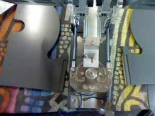
5 Step 1. Attaching the Rudder Pedal Lever Arm Rods. When you took delivery of your kit, the Rudder Pedal Lever Arm connecting rods (Red Arrow) and the Potentiometer leads will have been attached to the main body for transport. Remove the tape and attach the connecting rods to the Bell Crank through the holes marked with a White Arrow as shown in Fig.1. Using a 10mm spanner tighten the nuts securely. Once this has been done, move the Rudder Pedal Lever Arms backwards and forwards to ensure that you have no tight spots and that the transfer gear runs smoothly on the potentiometer gear. In production quality control, we will have marked the two gears with index marks. Please make sure that as the gears move, both index marks are synchronised with each other as they rotate. At this point, you may like to apply a small amount of grease to the arc cutout in the Bell Crank and also to the ball joint ends of the connecting rods. Step 2. Attaching The Side Blocks. Item #1 contains 4 sidewall blocks. Two short and two long. You will notice that the two short blocks have an angled edge which are attached with the angled edge to the front. Fix the four blocks to the baseplate with a fine point Crosshead screwdriver through the pre-drilled holes as shown in Fig.2. Step 3. Fitting The Pedal Units Item #3 (x2) contain the Left and Right Rudder/Brake Pedals. Item #4 contains the Nylon Wear Washers and Locking Collars for the Pedal Support Shafts. Take the Left Pedal and ensure the Support Shaft is fully pushed into the Pedal. You may care to add a little lubricant to the inside edge of the shaft. Place the centre shaft through the large machined hole in the Pedal Lever Arm as shown in Fig.3. The pedal assembly is fitted with a Brake Pedal Spring fulcrum lever and a drive gear for the Brake potentiometer. Carefully push the Pedal inwards ensuring that the fulcrum lever sits inside the limit cutout on the Lever Arm as shown in Fig.3 and at the same time that the two drive gears as mated so that the two index marks align as shown in Fig.4 by the Red Arrow.


6 Finally, place a Nylon Wear Washer onto the Pedal Shaft as shown in Fig.3 before finally fitting the Locking Collar onto the Pedal Support Shaft. Using a 5mm Allen Key, tighten the bolt in the Locking Collar to fix the pedal in place as shown in Fig.5. At this stage, we recommend that you check that there is no side to side movement in the Pedal and that it moves freely on it s axis and is driving the Potentiometer Gear. Now repeat the procedure to assemble the other Pedal onto it s Lever Arm. Step 4. Fitting The Brake Pressure Springs Item #2 contains 6 springs and all the Fixing Bolts to attach them. Take two springs and two 6mm Allen Bolts from the bag. Look at Fig.6 and identify the upper threaded hole on each Lever Arm as indicated by the Red Arrow. Place one of the Allen Bolts thru the eye on the end of the spring and screw it into place on both of the Lever Arms as shown in Fig.7. Please ensure that the spring sits against the lever arm properly. Because of the construction of the spring coil, one side has more space than the other side. Place the spring so that the side with the greater space is placed against the Lever Arm. This means the springs will fit squarely. Do not tighten yet. Using a 17mm spanner remove the two Nylok nuts as indicated in Fig.8 on the end of the end of the Fulcrum Lever spring anchor bolts. At this point, we would recommend that you enlist the help of a friend, colleague or even your wife because we are going to stretch the springs and fit them onto the bolts at the end of the Brake Pedal Fulcrum Levers. They are very strong springs and can be difficult to place working on your own. Stretch the spring using a Hook or Fine Nosed Pliers and place the eye on the spring onto the anchor bolt making sure that the springs are placed in a position on the bolt so that they are square as shown in Fig.8. Operate each Brake Pedal a number of times to satisfy yourself that the springs are working and seated correctly. Finally, tighten the 6mm Allen bolts into the Lever Arm and check the function of the return springs.


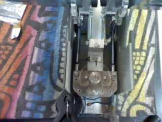
7 Step 5. Fitting the Rudder Pedal Tension Springs. In the Bag marked Item #2, you will still have four springs and four 6mm Allen bolts remaining. These are the Rudder Pedal Tension Springs and the bolts to fit them. On the centre Delrine Block, fore and aft of the Lever Arms, there are two aluminium spring anchor blocks fitted as indicated in Fig.9. These anchor blocks have a threaded hole machined into them on each side. Take two of the Tension Springs and attach them to the two remaining threaded holes in each of the Lever Arms as shown in Fig.10. Please bear in mind what we said about the spring having more space at the eye on one side in the previous section when fitting. Once the springs have been attached to the Lever Arm, we then have to stretch the springs and bolt them to the anchor block as shown in Fig.11. Again, we would recommend enlisting the help of a colleague when attempting this as these are very heavy springs and can cause some problems undertaking this operation if you are working alone. Once you have achieved this, that s it. All the mechanical assembly is complete and you should have a working assembly looking like this.


8 Step 6. Fitting The Covers Identify and select both the Left & Right Inner and Outer Sidewall Panels as shown in Fig.12. With each side in turn, place an Outer Panel over the Inner Panel so that they lay together neatly at all common edges and clamp as shown in Fig.13. Next drill a small Pilot Hole of 1.5mm through each of the predetermined screw holes in the bottom of each side panel as indicated by the red arrow in Fig.14. Place to one side. Next find item 7, the inner top cover support plate & item 8, the Outer Top Cover Plate as shown in Fig.15. Place the white inner support plate neatly under the Outer Cover so that it s edges match those of the Outer Cover as shown in Fig.16. Use your clamp to hold them together while you make 6 pilot holes through the top cover into the support plate as in Fig.17. Use the 6 screws provided to attach the two plates together. Once you have done this, we will now attach the 2 Top Sidewall Covers. These are the panels shown in Fig.18. Place one of the covers in place, so that the 3 pre-drilled holes in it align with the centre of the Top Cover Support Plate and mark with a pencil as in Fig.19. Drill 3 pilot holes in the Inner support Plate before attaching the top side cover with the screws provided. Repeat for both sides. Note: Now you have the major parts assembled, at this point we recommend that you have a Practise Assembly, so you understand how the components fit together. With the panels correctly placed in relation to each other, we will also prepare for final fitting by marking up the position of the side panels in relation to the baseplate.
9


10 Place the two side panels against the baseplate and clamp roughly in position. For correct positioning, move the side panel so that the cutout in the lower edge is central in relation to the lever arm shaft clamp block. Fit the top cover and ensure that the fixing parts fit nicely into the recesses in the sidewall. One this is achieved, this is the position where the covers will fit onto the rudder pedal assembly. Final Fixing of the Covers. When you are completely satisfied that the sidewall is correctly placed, mark a pecil line on the sidewall block as in Fig.21. Take the dimension from the rear of the sidewall block to the edge of the sidewall panel itself shown in Fig.22. Transfer this dimension to the other side. This ensures that your covers will fit evenly and square. Remove the outer sidewall panel and with the inner panel correctly in place, mark two holes both fore and aft of the lower cutout in the panel. Use a dimension of 25 30mm as shown in Fig.24. Make sure you avoid the pilot holes we drilled earlier. Drill and countersink the 4 holes each side and fix the inner sidewall to the sideblock as in Fig.26. Item 9 is the Top Cover Front Support Plate. Clamp it in position so that it is flush with the front edges of the sidewall panel and that it s top front corner lines up with the top front corner of the sidewall. Mark a line half way up. Drill and fix the support plate to the sidewalls with the two screws provided as in Fig.28 and 29.


11 Note: At this point, you may like to think about fixing your Pedals. Although access to the rear fixing screws is possible with the covers fitted, the front fixing holes are enclosed. So, now would be a good time to put your Rudders in place to mark up and drill the final fixing holes. Ok, let s fix the outer panels in place. Take an outer Sidewall Panel and place it in position against the inner panel so that the four pilot holes line up. Clamp it to prevent it moving. Take four of the small screws supplied and fix the panel in place. Repeat for the other side. Place the top cover in place making sure that it fits neatly at all the four contact points at the rear and front of the sidewall panel. Using eight of the small screws supplied, fix the top cover to the sidewall panel front and back, both sides. Press the front of the Top Cover down so that it fits neatly against both sidewall panels and the front support piece. Drill a pilot hole through the centre pre-drilled fixing hole and attach using one of the supplied screws. Finish by fixing the two side screws in place.


12 All that remains is to fix the front Lower Panel in place. There two options here. Drilling and screwing in place or using Contact Adhesive. Whatever you choose, please bear in mind that this panel needs to be fixed last of all after you have secured the front fixings.
13 All that remains to be done now is a final placing of the Footrests. We have designed these to be adjustable so that our Rudder Pedals can be used with most types of Yoke such as ACE & PFC etc. Position the footrests where you want them to be before fixing down with the two screws indicated at the front of the Footrest unit. Thank you for your purchase of our product and we hope you will have many years of faithful service from your new Revolution Simproducts Rudder Pedals. sales@revolution-simproducts.com
Post-Paint>Fuselage>Interior>Controls>Fit rudder pedals
 Post-Paint>Fuselage>Interior>Controls>Fit rudder pedals Objectives of this task: To fit the rudder pedals and steering links to the aircraft, and fit the rudder cable to the rudder pedals and set the deflection
Replacing the Reciprocator on the SWF Compact Series Machine (601C and 1201C)
") Follow the instructions below to replace the reciprocator in the SWF Compact series machines. The tools required can be found in the tool kit that came with the machine. Preparation 1. First, place the
Follow the instructions below to replace the reciprocator in the SWF Compact series machines. The tools required can be found in the tool kit that came with the machine. Preparation 1. First, place the
This manual will aid in the assembly of the FireBall V90 and FireBall X90. The assembly of both machines will be identical, unless specified.
 This manual will aid in the assembly of the FireBall V90 and FireBall X90. The assembly of both machines will be identical, unless specified. Step #1 Lay all parts out to verify quantities. (2) 2 x 25-1/4
TRAILMATE METEOR ASSEMBLY MANUAL
 TRAILMATE METEOR ASSEMBLY MANUAL The Trailmate Meteor recumbent has been designed for easy assembly. This means more time to enjoy the smooth ride with single speed, 3 speed coaster brake and 21 speed
Assembly Instructions: AM-10 Hand & Foot Cycle Early Intervention Part #: 50-HFC-0105
 Assembly Instructions: AM-10 Hand & Foot Cycle Early Intervention Part #: 50-HFC-0105 Refer to the following instructions on how to assemble your tryke. Study the instructions carefully before beginning
INSTALLATION GUIDE Rear Bumper. Jeep JL Wrangler
 INSTALLATION GUIDE Rear Bumper Jeep JL Wrangler Dual Swing System 1A From the stock bumper you removed from vehicle, you ll need to take the parking sensor wiring from it and feed it into the new bumper.
400A 40113V, 401A 40120V, & 401AL 40120VL ALUMINUM VERTICAL 4000 LB LIFT INCLUDES SCREW LEG ASSEMBLY INSTRUCTIONS
 12/11/07 PAGE 1 OF 12 400A 40113V, 401A 40120V, & 401AL 40120VL ALUMINUM VERTICAL 4000 LB LIFT INCLUDES SCREW LEG ASSEMBLY INSTRUCTIONS Thank you for purchasing our product! *Please read these instructions
Nancy s Knit Knacks LLC 4 Yard Option Upgrade Kit Assembly Instructions and User Manual
 Nancy s Knit Knacks LLC 4 Yard Option Upgrade Kit Assembly Instructions and User Manual Thank you for purchasing our 4 Yard Option (4YO) Upgrade Kit. To install this upgrade you are simply going to assemble
ASSEMBLY INSTRUCTIONS DIY WALL BED KIT QUEEN BI FOLD DOOR CABINET & MECHANISM. Tools Required For Assembly. 6.5mm Masonry Drill Bit
 ASSEMBLY INSTRUCTIONS DIY WALL BED KIT QUEEN BI FOLD DOOR CABINET & MECHANISM Tools Required For Assembly No 2 & No 4 Phillips Head Screwdrivers No 2 Slot Head Screwdriver Hammer Electric Drill (Hammer
STENCIL MACHINE OPERATION uline.com H-259, H-347 H-408 CUTTING THE OIL BOARD INSERTING THE OIL BOARD
 H-259, H-347 H-408 π STENCIL MACHINE 1-800-295-5510 uline.com OPERATION NOTE: No assembly is necessary after you unpack your machine. INSERTING THE OIL BOARD 1. Move the release lever to the right. This
Astro-Physics Inc. 400QMD Lubrication/Maintenance Guide
 Astro-Physics Inc. 400QMD Lubrication/Maintenance Guide The following guidelines should be followed to lubricate the three main parts of the 400QMD mount. The QMD stands for Quartz Micro-Drive controller.
V4 Premium Kit. Prusa i3 Build Guide
 V4 Premium Kit Prusa i3 Build Guide Hi! Congratulations on your purchase of the DIYElectronics.co.za Prusa I3 kit, the best South African 3D Printer Kit! Hopefully this should serve as complete guide to
Installation Instruction
 Tools Needed for Assembly Stud finder (for wood stud wall) Pencil Mark Electric drill Wood Stud Wall Installation Step 1. Locate the Wood Studs Installation Instruction Drill bit (for wood stud wall) Masonry
Side Mount INSTRUCTION BOOKLET #C122 BED STYLE: PARK CITY
 Side Mount BED STYLE: PARK CITY INSTRUCTION BOOKLET #C1 WARNING! ALL MURPHY/WALLBED SYSTEMS CONTAIN STORED ENERGY. FAILURE TO USE AND FOLLOW THESE INSTRUCTIONS DURING THE INSTALLATION PROCESS COULD RESULT
It is highly recommended that you use a thread lock compound such as Loctite brand on all threads to keep them from vibrating loose.
 Installation instructions for FC12 Forward Controls for Kawasaki Vulcan 750 It is highly recommended that you use a thread lock compound such as Loctite brand on all threads to keep them from vibrating
Mount to the Wall INSTALLATION MANUAL
 Mount to the Wall 15 Locate the Wooden Studs This step applies to wooden stud wall installation only. Determine and mark the exact locations of two stud centers on the wall. Wooden studs should be spaced
M4 Foot Operated Underpinner Instruction Manual
 M4 Foot Operated Underpinner Instruction Manual M4 Walker Rd, Bardon Hill, Coalville, Leicestershire LE67 1TU, England Tel. +44 (0)130 1692, Fax +44 (0)130 16929 e mail sales@framerscorner.co.uk M4 Underpinner
3.2.3 Rear Door Window and Quarter Window Carrier Assembly
 Tighten all bolts. Tighten bolts marked -1- and -2- in specified sequence. Tightening torque: 8 Nm Remaining bolts can be tightened in any sequence. Insert door window -3- through window recess without
Heavy Duty Ceiling Tilt Mount Installation Manual
 HD-CTM-5580 Heavy Duty Ceiling Tilt Mount Installation Manual *This Installation requires a minimum of two people. For your safety: Read the complete instruction manual before starting an installation
RC4WD (R2D) R2 Disconnect Transmission Sideway Servo Mount Installation
 R2 Disconnect Transmission Sideway Servo Mount Installation") RC4WD (R2D) R2 Disconnect Transmission Sideway Servo Mount Installation In this manual you will find out how to install the R2D Sideway servo mount. The disconnect tranny is used to help in competition
RC4WD (R2D) R2 Disconnect Transmission Sideway Servo Mount Installation In this manual you will find out how to install the R2D Sideway servo mount. The disconnect tranny is used to help in competition
Zen Toolworks CNC Carving Machine DIY Kit User Installation Manual
 User Installation Manual Visit Us At: http://www.zentoolworks.com or http://www.zentoolworks.com/zenwiki/mediawiki Contact Us At: zentoolworks@gmail.com 1 P-01, Nema 17 Stepper Motor, 3 P-02, Motor Shaft
Replacing the Reciprocator on an SWF Multi-head.
 Replacing the Reciprocator on an SWF Multi-head. Follow the instructions below to replace the reciprocator in the SWF multi-head machines. The tools required are found in the tool kit that came with the
BABY WOLF LOOM. Assembly Instructions for Knocked-Down Looms
 BABY WOLF LOOM Assembly Instructions for Knocked-Down Looms BEFORE YOU BEGIN Please read through the directions before beginning to assemble your loom. Unpack the loom parts carefully. Do not throw away
PFW 6875 Installation Guide Installationsanleitung, Guía de Instalacíon, Guida de Installazione, Guide d Installation, Installatie gids
 Maximum Flat Panel Weight: 160 lb. / 72.57 kg. Included Components Wall Mount (Qty 1) Extension Brackets (Qty 2) Bracket (Qty 1 Pair) 5/16 Flat Washers (Qty 4) Universal Spacers (Qty 8) M5 Allen Driver
MOTORIZED STANDARD SHADE WITH CABLES Installation Instructions
 Tools Needed Drill Measuring Tape Pencil 2 Level Plumb Line ¼ Masonry Drill Bit Hammer Linesmans Pliers Cable Cutters Phillips & Flat-Head Screw Driver 11/32 Socket or Open End Wrench 5/32 Allen Wrench
REPAIR INSTRUCTIONS. Cat. No Cat. No MILWAUKEE ELECTRIC TOOL CORPORATION. SDS Max Demolition Hammer. SDS Max Rotary Hammer
 Cat. No. 9-0 SDS Max Demolition Hammer Cat. No. -0 SDS Max Rotary Hammer MILWAUKEE ELECTRIC TOOL CORPORATION W. LISBON ROAD BROOKFIELD, WISCONSIN 00-0 8-9-0 d 000 8-9-0 d Special Tools Require Forcing
30DC Speed Lathe Manual
 30DC Speed Lathe Manual The Crozier Model 30DC Speed Lathe is our most popular model. It has many standard features not found on any other machine in its class or price range. Standard Features 3/4 HP
Technical Procedure. HIITMill (X) Push/Pull Brake Cable Install
 Push/Pull Brake Cable Install") HIITMill (X) Push/Pull Brake Cable Install Applies to: HIITMill and HIITMill X Required Tools: 2.5mm Allen Key 3mm Allen Key 4mm Allen Key 5mm Allen Key 6mm Allen Key 10mm Wrench 10mm Socket Ratchet Needle
HIITMill (X) Push/Pull Brake Cable Install Applies to: HIITMill and HIITMill X Required Tools: 2.5mm Allen Key 3mm Allen Key 4mm Allen Key 5mm Allen Key 6mm Allen Key 10mm Wrench 10mm Socket Ratchet Needle
Alleweder a8 construction manual
 v 1.0.0 The Frame Part 1 THE FRAME PART 1 The Alleweder a8 obtains its structural integrity from a frame wich consists of crosswise and lengthwise construction parts. The crosswise oriented parts are called
Large Wood Windmill Assembly Instructions
 CROW S NEST (TOP VIEW) TOWER (SIDE VIEW) 0 QTY 2 2 ITEM QTY 2 QTY QTY 8 QTY 8 QTY 4 TOP TOP TOP 47 9 QTY 4 QTY 4 QTY 4 QTY 4 QTY 4 ITEM 6 ITEM 7 ITEM 8 ITEM 3 ITEM 9 ITEM 4 ITEM 2 ITEM 5 47 Leg QTY 4 42.5
Side Winder R o u t e r L i f t.
 Woodpeckers PRECISION WOODWORKING TOOLS Side Winder R o u t e r L i f t. INSTALLATION INSTRUCTIONS The wrench handle must be pointing left in order to fully insert or remove it. Lift Wrench Once fully
MS2 Straight Key Kit Assembly Manual
 American Morse Equipment MS2 Straight Key Kit Assembly Manual Thank you for purchasing our MS2 Miniature Straight Key Kit! Please take a few minutes to look over these instructions before starting assembly.
Bunk Pod Front Entry Assembly Instructions
 Bunk Pod Front Entry Assembly Instructions www.podtime.co.uk enquiries@podtime.co.uk Working House Ltd How to assemble your pod This step by step guide will show how to assemble your pod(s) on site. It
ELECTRIC TOOL CORPORATION
 Cat. No. -0 / Hex Demolition Hammer Cat. No. 0-0 Spline Rotary Hammer MILWAUKEE ELECTRIC TOOL CORPORATION W. LISBON ROAD BROOKFIELD, WISCONSIN 00-0 -9-00 d 000 -9-00 d SpecialTools Require Forcing discs
Installation instructions for FC14S Forward Controls for Shadow ACE and Aero 1100
 Installation instructions for FC14S Forward Controls for Shadow ACE and Aero 1100 It is highly recommended that you use a thread lock compound such as Loctite brand on all threads to keep them from vibrating
RC4WD Diablo V2 Instruction Manual
 Version 1.1 RC4WD Diablo V2 Instruction Manual Thank you for your purchase. Welcome to the RC4WD family. This kit is a combination of many specially engineered and manufactured parts. Enjoy your build.
A500 ASSEMBLY & INSTALLATION INSTRUCTIONS
 ASSEMBLY & INSTALLATION INSTRUCTIONS 1 CONTENTS 2 Component Parts A B Canopy Mounting Plate C Cap (3) D Threaded Nipple E Threaded Standoffs (2) F Anchors (8) G #10 Screws (8) H Safety Cable (2) I Safety
Baby Grande or Grande Crank Shade with Cables and Housing Installation Instructions
 Baby Grande or Grande Crank Shade with Cables and Housing Installation Instructions Tools Needed Drill 3/8 Metal Drill Bit Screwdriver (Flat & Phillips) Measuring Tape Pencil 4 Level Plumb Line ¼ Masonry
Castle Frame Assembly Table AT-8. Diagnostics Manual. Castle, Inc. Petaluma, CA
 Castle Frame Assembly Table AT-8 Diagnostics Manual Castle, Inc. Petaluma, CA 800-282-8338 Solutions Index Adjusting the Tabletop.. 8.01 Adjusting the Fence... 8.02 Aligning the Arm... 8.10 Adjusting Bracket..
PFW 6851 Display Wall Mount, Turn & Tilt 80 kg INSTALLATION INSTRUCTIONS
 Display Wall Mount, Turn & Tilt 80 kg INSTALLATION INSTRUCTIONS 9531-007-Z00-01 Table of Contents Warning Statements 2 Parts List 3 Installation Tools 3 Wood Stud Installation 5 Concrete Surface Installation
SFP-550. Maintenance Manual MATSUHIDAI, MATSUDO-CITY, CHIBA JAPAN TEL: FAX:
 SFP-550 Maintenance Manual 296-1 MATSUHIDAI, MATSUDO-CITY, CHIBA 270-2214 JAPAN TEL: +81-47-388-6111 FAX: +81-47-388-4477 Introduction This manual covers items and procedures for the periodic inspection
3D PRINTER. Pack 11. Anything you can imagine, you can make! 3D technology is now available for you at home! BUILD YOUR OWN
 BUILD YOUR OWN Pack 11 Anything you can imagine, you can make! 3D PRINTER Compatible with Windows 7 & 8 Mac OS X 3D technology is now available for you at home! BUILD YOUR OWN 3D PRINTER CONTENTS PACK
200A FLB VERTICAL 22113V LIFT W/CHAIN DRIVE WINCH
 PG. 1 OF 11 PORTA-DOCK, INC. 200A FLB VERTICAL 22113V LIFT W/CHAIN DRIVE WINCH STEP 1. Separate and group like parts and fasteners together. Locate the winch side member with the longer upright tube and
Installation Instructions
 For Medium (15-18.5K) + Heavy duty (-8.5K) Air Conditioner READ BEFORE INSTALLING UNIT To avoid risk of personal injury, property damage, or product damage due to the weight of this device and sharp edges
The Portable Open Source 3D Printer
 http://web.archive.org/web/201502142011/http://www.tantillus.org/build_3.html Page 1 of 12 captures 12 Oct 12 - Feb 15 The Portable Open Source 3D Printer Home Start Case X/Y Axis Extruder Z Axis Electronics
Assembly Instructions 10 X 10 Aluminum Roof Support
 Assembly Instructions 10 X 10 Aluminum Roof Support Aluminum Roof Support Bolt Package 16-5/16 X 2 ¼ SS Bolt 24-5/16 X 1 SS Bolt 40-5/16 SS Nylon Lock Nuts 16-5/16 SS Flat Washers 28-4 ½ Wood Screws 36-1
Baby Grande or Grande Crank Shade with Cables and Housing Installation Instructions
 Baby Grande or Grande Crank Shade with Cables and Housing Installation Instructions Tools Needed Drill 3/8 Metal Drill Bit Screwdriver (Flat & Phillips) Measuring Tape Pencil 4 Level Plumb Line ¼ Masonry
WILDING WALLBEDS INSTALLATION INSTRUCTION Side Mount
 WILDING WALLBEDS INSTALLATION INSTRUCTION Side Mount For Wallbed models: Do-It-Yourself Insturction booklet C92 WARNING! ALL MURPHY/WALLBED SYSTEMS CONTAIN STORED ENERGY. FAILURE TO USE AND FOLLOW THESE
Installation Instructions for FC2 & FC15 Forward Controls for the Super Magna
 Installation Instructions for FC2 & FC15 Forward Controls for the Super Magna It is highly recommended that you use a thread lock compound such as Loctite brand on all threads to keep them from vibrating
WARNING: THERE IS ALWAYS A DANGER OF INJURY WHEN
 Assembly Instructions: AM 10 Hand & Foot Cycle Early Intervention Part #: 50 HFC 0105 Refer to the following instructions on how to assemble your tryke. Study the instructions carefully before beginning
Under Seat Storage Drawer Installation Instructions
 Under Seat Storage Drawer Installation Instructions Parts List: 1) Drawer Assembly 8) Self Tapping Screws 1) Instructions 1) Template Tools Needed: Drill and/or Bit Driver Tape Measure Jigsaw or metal
PLEASE READ THIS NOTICE BEFORE BEGINNING ANY PHASE OF INSTALLATION!!!!
 PLEASE READ THIS NOTICE BEFORE BEGINNING ANY PHASE OF INSTALLATION!!!! This kit is designed to be installed by someone with a fair amount of mechanical aptitude. However, if you are not comfortable making
Motorized M3 AX7200 Rotary-Style Gasket Cutter Operating Instructions
 Motorized M3 AX7200 Rotary-Style Gasket Cutter Operating Instructions INTRODUCTION Congratulations! You are the owner of the finest rotary-style gasket cutter in the world. Originally developed and patented
American Morse Equipment
 American Morse Equipment Thank you for purchasing an American Morse Porta Paddle-II Kit. We redesigned the original Porta Paddle for ease of assembly & provide all parts finished and ready for assembly,
MantelMount. TM1A Installation Instructions IMPORTANT SAFETY INSTRUCTIONS - SAVE THESE INSTRUCTIONS
 MantelMount TMA Installation Instructions IMPORTANT SAFETY INSTRUCTIONS - SAVE THESE INSTRUCTIONS TM Thank you for choosing the MantelMount television wall mount. Please read this entire manual before
Ruby 0-4-0T Kit Assembly Instructions
 Ruby 0-4-0T Kit Assembly Instructions Ruby Parts List PART NO.& NAME QTY PART NO.& NAME QTY SHEET 1 1 Frame 2 2 Bracket 4 3 M2 x 4 Hex Head Screw 25 4 Wheelset (without eccentrics) 1 5 Wheelset (with eccentrics)
Code Product Qty 1 Top Vertex 3 2 Hot End Housing 1 3 Bottom Vertex 3 4 Print Platform Lock 3 5 End Stop Holder 3 6 Filament Feeder Motor Bracket 1 7
 List of Parts Code Product Qty 1 680mm Extrusion 3 2 Power Supply 1 3 240mm Extrusion 9 4 42mm Nema 17 Stepper Motor 3 5 Slider-Hotend Connecting Rod 6 6 48mm Nema 17 Stepper Motor 1 7 Linear Rail with
Written By: Brook Drumm
 Simple 1401 Assembly For kits produced between 1/15/14-6/1/14. This guide is for kits with the Fan Shroud. Instructions for metal and wood extruder (and bed) included below. Written By: Brook Drumm TOOLS:
INSPECTION AND CORRECTION OF BELLHOUSING TO CRANKSHAFT ALIGNMENT
 INSPECTION AND CORRECTION OF BELLHOUSING TO CRANKSHAFT ALIGNMENT BACKGROUND Proper alignment of the transmission input shaft to the crankshaft centerline is required in order to achieve the best results
GlideRite Retractable Cover System For HotSpring & Tiger River Spas (except Classic & pre-2000 Landmark Spas)
") List of Contents Quantity Description 12 #10 x 1 ½ Flat Head Phillips Screw (see pg. 2) 2 #10 x ½ Pan Head Phillips Screw (see pg. 2) 8 ¼ x 2 ½ Lag Bolt (see pg. 2) 7 ¼ 20 x 5 / 8 Hex Head Bolt (see pg.
List of Contents Quantity Description 12 #10 x 1 ½ Flat Head Phillips Screw (see pg. 2) 2 #10 x ½ Pan Head Phillips Screw (see pg. 2) 8 ¼ x 2 ½ Lag Bolt (see pg. 2) 7 ¼ 20 x 5 / 8 Hex Head Bolt (see pg.
Hubble GOTO Installation Instruction (1.3, 04/30/2014)
") Hubble GOTO Installation Instruction (1.3, 04/30/2014) 1. Preparation... 1 1.1 Tools required... 1 1.2 AZ GOTO Drive Parts List...1 1.3 ALT GOTO Drive Parts List... 1 2. The Azimuth motor drive installation...2
Hubble GOTO Installation Instruction (1.3, 04/30/2014) 1. Preparation... 1 1.1 Tools required... 1 1.2 AZ GOTO Drive Parts List...1 1.3 ALT GOTO Drive Parts List... 1 2. The Azimuth motor drive installation...2
PFW Installation Guide Installationsanleitung, Guía de Instalacíon, Guida de Installazione, Guide d Installation, Installatie gids
 Maximum Flat Panel Weight: 100 lb. / 45.35 kg. Included Components Wall Mount (Qty 1) Extension Bracket (Qty 1 Pair) Bracket (Qty 1 Pair) 5/16 Flat Washers (Qty 4) Universal Spacers (Qty 8) M5 Allen Driver
Technicians of Terror. This is the air valve we make to use with our air
 These are pictures of our scissor prop. Technicians of Terror http://www.halloweenfear.com/scissorprop.html props. This is the air valve we make to use with our air This pictures the duel door closer cylinders
Thank you for purchasing our product! *Please read these instructions and follow them step by step.*
 07/07/08.rev1 PAGE 1 OF 11 601AL VERTICAL 60120VL LIFT W/CHAIN DRIVE WINCH Thank you for purchasing our product! *Please read these instructions and follow them step by step.* Step 1. Separate and group
Your new. Rose. spinning wheel. majacraft. all you need to spin your dreams... majacraft
 Your new Rose spinning wheel all you need to spin your dreams... 1 Welcome to the Majacraft family Congratulations on purchasing a new Majacraft Rose. We are very proud of this wheel and hope that it allows
Installation instructions for FC9 & FC18 Forward Controls for Yamaha V-Max
 Installation instructions for FC9 & FC18 Forward Controls for 1985-2007 Yamaha V-Max It is highly recommended that you use a thread lock compound such as Loctite brand on all threads to keep them from
6000 Horizontal Router Table Owners Manual Please Read Carefully!
 6 Horizontal Router Table Owners Manual Please Read Carefully! Parts List Please identify and verify that you have all of the hardware & parts shown prior to assembly. The parts described in this box are
RBP-1215B-RX DODGE RAM QUAD CAB RX3
 RBP-1215B-RX3 2002-2017 DODGE RAM 15-3500 QUAD CAB RX3 Passenger side RX-3 Side Step Drill Template Passenger side rear Modular Bracket (6) L Support Brackets Driver side rear Modular Bracket Driver side
Medium Pro Table Top Stand
 Medium Pro Table Top Stand Build Manual Thank you for purchasing a Foam-Flite model airplane stand. Your Foam-Flite stand was designed by modelers just like you looking for an economical and versatile
 INSTRUCTION BOOKLET #C0 Watch step by step installation instructions at: https://www.wallbedsbywilding.com/wallbed-installation-studio-series/ WARNING! ALL MURPHY/WALLBED SYSTEMS CONTAIN STORED ENERGY.
General Features. Low Profile. The SMART BOXX stands only 1.5 off of the bed of your truck so cargo space is maximized
 General Features Low Profile. The SMART BOXX stands only 1.5 off of the bed of your truck so cargo space is maximized Two Sizes Short Box :74 L X 47 W X 7 T and Long Box 92 L X 47 W X 7 T All Aluminium
Hardware and Components:
 Hardware and Components: (A) 5/16 x 2 Hex Bolt (B) 5/16 x 2-1/4 Hex Bolt (C) 5/16 x 2-1/2 Hex Bolt (D) 4X 5/16 x 3/4 Hex Bolt (E) 4X 5/16 x 1-1/4 Hex Bolt (F) 11X 5/16 Flat Washer (G) 12X 5/16 Nylock Nut
Hardware and Components:
 Hardware and Components: (A) 4X 5/16 x 1 Carriage Bolt (B) 2X 5/16 x 2-1/4 Carriage Bolt (C) 2X 5/16 x 3-1/4 Hex Bolt (D) 2X 5/16 x 3/4 Hex Bolt (E) 2X 5/16 x 1-1/4 Hex Bolt (F) 5/16 x 2-1/4 Hex Bolt (G)
REPAIR INSTRUCTIONS: CABLE
 The repair instructions describe replacing the Cable in the Easy Sun PARASOL Sunshade. These repair instructions are intended only for persons with experience of using the tools required. Please read the
EXIT DEVICE OPERATION FIRE DOOR LABELS, STRIKES AND FRAME SCREWS FOR INFORMATION CALL OR VISIT RITEDOOR.COM
 RECORD & LABELS WHAT THIS OWNER'S CAN DO FOR YOU It explains exactly how The Rite Door operates. It explains periodic maintenance requirements necessary to assure reliable operation. It explains simple
1. Turn off or disconnect power to unit (machine). 2. Push IN the release bar on the quick change base plate. Locking latch will pivot downward.
. 2. Push IN the release bar on the quick change base plate. Locking latch will pivot downward.") Figure 1 Miniature Quick Change Applicators, of the end feed type, are designed to crimp end feed strip terminals to prestripped wires. Each applicator is set up to accept the strip form of certain specific
Figure 1 Miniature Quick Change Applicators, of the end feed type, are designed to crimp end feed strip terminals to prestripped wires. Each applicator is set up to accept the strip form of certain specific
Introduction. Rocky Mountain Westy Swing Away Carrier Kit Installation Instructions
 Rocky Mountain Westy Swing Away Carrier Kit Installation Instructions Introduction Thank you for purchasing the Rocky Mountain Westy Swing Away Carrier Kit. We pride ourselves in the products we develop
STRINGING MACHINE OWNER'S MANUAL. Copyright 1998 GAMMA Sports - All Rights Reserved
 6002 STRINGING MACHINE OWNER'S MANUAL Issue 3 - June 20, 1998 Copyright 1998 GAMMA Sports - All Rights Reserved 6002 OWNER'S MANUAL TABLE OF CONTENTS PAGE 1... WARRANTY PAGE 2... FEATURES PAGE 3... ASSEMBLY
mila-wall (Series100) General Operating Instructions page 1 of 15
 General Operating Instructions page 1 of 15") mila-wall (Series100) General Operating Instructions page 1 of 15 Step #1: Before setting up walls, lower adjustable leveling feet on each panel approximately 1". This will allow access to the threaded
mila-wall (Series100) General Operating Instructions page 1 of 15 Step #1: Before setting up walls, lower adjustable leveling feet on each panel approximately 1". This will allow access to the threaded
Sit Down Table Assembly Instructions
 Sit Down Table Assembly Instructions Parts that come with your sit down table A B C D E F G H I J K L M N Extension leaf Table with cutout for machine Two table legs One table leg with long support One
 INSTRUCTION BOOKLET #C10 Watch step by step installation instructions at: https://www.wallbedsbywilding.com/wallbed-installation-studio-series/ WARNING! ALL MURPHY/WALLBED SYSTEMS CONTAIN STORED ENERGY.
Removing the Z-Axis lead screw
 Page 1 of 8 TITLE: Sabre Z-Axis Lead Screw Replacement Procedure Gerber FastFact #: 5048 Supplied by: Gerber Hardware Support Last Modified: June 14, 2007 Summary: Tools used: The following procedure explains
INSTALLATION INSTRUCTIONS
 INSTALLATION INSTRUCTIONS Universal Swingout Arm Model: AM300/AM300-B NORTH AMERICA 3130 East Miraloma Avenue Anaheim, CA 92806 USA USA and Canada Phone: 1.800.368.9700 Fax: 1.800.832.4888 Other Locations
Chapter 6 Frame And Lens Repairs
 Chapter 6 Frame And Lens Repairs 6.1 General Information All maintenance on the frame of the EXO Full-Face mask can be accomplished with common hand tools. 6.2 Lens Replacement Tools required: Dow DC-111
EZ-Lock Assembly Manual
 ABM International, Inc. EZ-Lock Assembly Manual 1 ABM International, Inc. Series: 1018/1022/1026 V1.0 EZ-Lock Parts List - Structural frame profiles Slotted beam: (Qty. 2) 15.75 Commercial Parts - Liner
3/8-16 x 3/4 cap screw. 3/8-16 hex nut for above screws. 1/4-20 x 3/4 socket cap screw. 3/16 short arm hex key (not to scale)
") Super Slab Roller 24, 30 and 36 models Worktable Assembly Directions P.O. Box 89 Cheney, WA 99004 USA 509.235.9200/800.23.7896 Fax: 509.235.9203 www.northstarequipment.com Revised September, 2006. All
Super Slab Roller 24, 30 and 36 models Worktable Assembly Directions P.O. Box 89 Cheney, WA 99004 USA 509.235.9200/800.23.7896 Fax: 509.235.9203 www.northstarequipment.com Revised September, 2006. All
N. 15th Street, Middlesboro, KY FLIP TARP DUMP BODY INSTALLATION INSTRUCTIONS
 1-800-248-7717 1002 N. 15th Street, Middlesboro, KY 40965 FLIP TARP DUMP BODY INSTALLATION INSTRUCTIONS Congratulations on your purchase of a Mountain Flip Tarp Dump Body tarping system. With tarping systems
How To Measure Your Finished Opening
 3000 Series Bifold Doors How To Measure Your Finished Opening MEASURE FROM RIGHT TO LEFT 2 PLACES (WIDTH) MEASURE FROM TOP TO BOTTOM 2 PLACES (HEIGHT) Tools Required for Assembly: Tools Needed: Phillips
AndyMark DART 12.
 AndyMark DART 12 Part Number Description QTY These Parts Are Pre-Assembled by AndyMark am-0031 Bearing, 3/16"ID (R3) 1 am-0209 Bearing, 3/8"ID 1614ZZ 2 am-1028 Screw, #10-32x3/8 Pan Head Philips 8 am-1121
ELIZABETH 30 SPINNING WHEEL
 INSTRUCTIONS ELIZABETH 30 SPINNING WHEEL Single and Double Treadle Ashford Handicrafts Ltd. Factory and Showroom: 415 West Street, PO Box 474, Ashburton, New Zealand Telephone 64 3 308 9087 Facsimile 64
Assembly Aid. One of the packages contains the required bolts, washers and nuts for final assembly
 Assembly Aid Open the box and arrange the pieces similar to what you see here. Assembly instructions as well as the list of tools required for assembly are also in the box. One of the packages contains
Clock 35 - Toyland. Construction instructions for Clock 35
 This clock has been designed for children, it is a stand-alone unit and can be positioned on a shelf or cabinet out of the reach of very young hands who may be tempted to touch. The clock is shown in two
Basic steps to time the Gammill quilting machine s rotary sewing hook
 Basic steps to time the Gammill quilting machine s rotary sewing hook 1.) Turn the machine off and unplug it. 2.) With the needle bar in the raised position, remove the bobbin and bobbin case. 3.) Remove
ASAP Sr. A Strap and Pole. Magic Christmas. Single Stage. Walter Monkhouse. Alexandria, La. Version 1.2.
 ASAP Sr Single Stage A Strap and Pole Version 1.2 Walter Monkhouse Walter@MagicChristmas.org Magic Christmas Alexandria, La. Description The ASAP Sr, single stage, has the same concept as the ASAP Jr.
3. Remove the flue collar by backing out the two Phillips round head machine screws.
 SERVICE MANUAL SERVICE PROCEDURES Defiant Non-Catalytic Model 1610 Woodstove **Wear gloves, a dust mask and protective eyewear when servicing a stove. ** Replacing the Fountain Assembly 1. Remove the doors,
https://www.wallbedsbywilding.com/wallbed-installation-studio-series/
 For Wallbed models: KING SIZE INSTRUCTION BOOKLET #C1 Watch step by step installation instructions at: https://www.wallbedsbywilding.com/wallbed-installation-studio-series/ WARNING! ALL MURPHY/WALLBED
1 of 2 3/3/2017 4:49 PM
 1 of 2 3/3/2017 4:49 PM Front Door Window, Assembly Overview 1 - Window guide - Inserted on flange 2 - Door 3 - Inner window recess seal - Inserted on flange 4 - Bolt - 20 Nm 5 - Carrier assembly - Window
INSTALLATION: D1-NOTCH DRYWALL TRIM FLANGE
 T F W 604.549.979 604.549.9555 fluxwerx.com INSTALLATION: D1-NOTCH DRYWALL TRIM FLANGE fixture housing endcap kit optic kit join kit notch 2 cross section notch 4 cross section 4 4" 4-11/2" 4 /8 (111)
Gared Pro-S Portable Backstop
 Models: 9616 & 9618 Installation, Operation and Maintenance Instructions Please read all instructions before attempting installation or operation of these units SAVE THESE INSTRUCTIONS FOR FUTURE USE PUBLICATION
Warnings. Description. Prior to Installation Tools Needed
 Warnings Failure to act in accordance with the following may result in death or personal injury. The JT Strong Arm Stabilizer System is intended to eliminate chassis movement in travel trailers and fifth