CONTENTS THE ADVANCE PASTEMATE ADVANTAGES ENGLISH
|
|
|
- Mary Reynolds
- 6 years ago
- Views:
Transcription
1
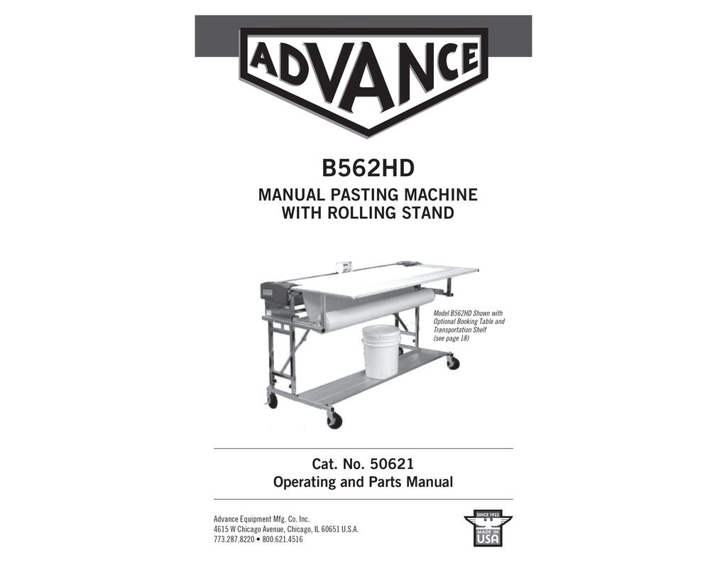
2 THE ADVANCE PASTEMATE ADVANTAGES Introduced in September 1981, thousands in service, known for reliability and performance. Setup and clean-up is faster than any other paste machine, which means more production. One filling of the tank will paste more wallcovering than any other machine. Exclusive paste control system pastes all materials, vinyl, string, suede, burlap and grasscloth without staining the face. Five rollers all geared together for better paste application. Lifetime warranty on the stainless steel paste tank and five years on the drive gears. In house manufacturing using computer controlled machinery for consistent quality and longer life. Replacement parts are shipped within 24 hours. Free consultation with experienced technicians prior to purchase will insure the right product for your needs. 100% satisfaction guaranteed! Follow these instructions for operating the B562-HD PASTING MACHINE with ROLLING STAND. PLEASE READ THEM COMPLETELY BEFORE STARTING CONTENTS General Assembly... 2 General Instructions... 3 Adhesives... 4 Booking Table Option... 5 Opening Side Covers... 6 Pasting Operations Paste Control Roller Installation and Adjustment... 8 Measuring Counter Operation... 9 Cleaning Storage and Transport Warranty... 4 Specifications... 2 Parts Lists and Drawings Anodizing... 4 Important Options PAGE 1
3 GENERAL ASSEMBLY side cover latch paste tank locking pin Fig. 1 folding brace rolling stand leg assembly guide stay shaft reverse feed roller material guide cone paste tank brackets cutting base locking pin locking screw caster assembly optional booking table material shaft support brackets material shaft GENERAL INSTRUCTIONS 1) Before lifting machine from shipping box, remove accessory tool box, the material support bar and the two caster assemblies packed next to the machine. 2) Lift out machine by grabbing the stand under the tank. (Two people will be easier) 3) Set machine next to the shipping box. 4) Open rolling stand: a) Lift up one end of machine and open leg assembly (#1313), put legs on floor, lock folding brace (#1314) with steel pin (#1309). Lift other end and repeat procedure. 5) Install caster assemblies: a) Lift machine at one end and slip caster assembly tubes into tubes of leg assembly. Make sure that casters extend forward towards front of machine (latch side of machine). Repeat with other end. b) Raise machine to insert steel pins (#1311) in caster assembly at desired height. Lock in position by tightening black plastic head lock screws (#1308). 6) Remove stainless steel cover. 7) Unlock both quick releases (latches) on machine lid and open lid. Remove packaging material from rollers in tank. 8) Close lid of machine and with your hand on rubber covered reverse feed roller, rotate rollers and check that they rotate smoothly without any binding. 9) Always lay rollers down on a dropcloth when removed from the tank. Do not lean them against a wall or table, they may get damaged if dropped. 10) We recommend removing and cleaning the rollers each night to insure long life. Adhesive can be left in the tank overnight. SPECIFICATIONS CATALOG No MODEL B562-HD WITH ROLLING STAND HEIGHT (rolling stand open) /4 in. HEIGHT (rolling stand folded) /2 in. LENGTH /4 in. WIDTH in. WEIGHT (machine) lbs WEIGHT (accessories) lbs. OPTIONAL BOOKING TABLE CATALOG No. 562BT lbs. OPTIONAL STORAGE CASE CATALOG No lbs. OPTIONAL TRANSPORTATION SHELF CATALOG No. 562TS lbs. PAGE 3
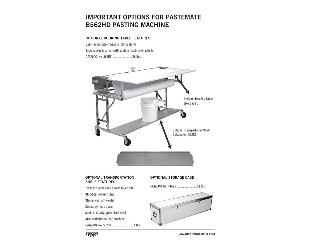
4 ADHESIVES With a deep paste tray and a pickup roller, most types of paste may be used in the machine. However, successful machine operation depends to a great extent on the right paste consistency. Working with the machine will teach you how properly prepared paste should look. As a guide, it should have the consistency of heavy pancake batter. The paste will, in most cases, have to be thinned with water and should be thoroughly mixed, using an electric mixer. When using clay based adhesives, pull the maximum number of sheets from one filling of the tray to prevent the paste settling in the tray. Then add paste and pull the next batch. Clay adhesives will have to be agitated again when left at rest for some time. Note: The machine rollers are made of aluminum alloy which is hard anodized after being machined. This process puts a hard coating on the surface and hardens the base aluminum to the same depth. This makes the aluminum more wear resistant than hardened steel. However, if the adhesive is excessively acid or alkaline, it may cause roller pitting and you should change your adhesive. To protect your rollers, remove and clean them every night and use an adhesive with ph range of 5.0 to 8.5. BOOKING TABLE OPTION 1. Remove square tube end caps from rolling stand and insert booking table support brackets on left and right side. Lock in place by turning locking bracket. 2. Board supports will be in front of machine over material support bar. 3. Lay both basswood boards in supports after you have installed wallcovering material on supports and have loaded it into the machine. 4. You are now ready for operation. 5. Maintain your basswood boards by lightly re-sanding and resealing once a year. Fig. 2 ANODIZING We protect the aluminum rollers in our pasting machines by hard anodizing them. The anodizing is done in accordance with ASTM (American Society of Testing Materials) military specifications and we use type Ill, which is the hardest coating. The aluminum used is type 6061, which accepts the anodizing process very well. Anodizing is an electrochemical process, which builds a coating of.001 to.0015 to the surface of the roller and penetrates the same amount below the surface. This hardcoat will be file hard and have a Rockwell hardness of and the wear resistance is superior to hardened steel. Hard anodized coatings will not peel, since the coating is an integral part of the base metal. As the coating thickness increases, the time capillary pores microscopically form a honeycomb pattern, that seals itself, making the roller exceptionally corrosion and wear resistant. However, it should be noted that strong caustic solutions or acids may cause pitting or the hardcoat to disintegrate. Therefore, it is recommended that adhesives used in the machine should have a ph factor, which is close to neutral, in the range 5.0 to 8.5. It should be mentioned that the color of the roller is affected by the composition of the aluminum alloy and will range from dark gray/brown to dark black. WARRANTY Paste-Mate pasting machines are warranted for 12 months from date of purchase, by the original purchaser, against defective materials and workmanship, provided it has been installed and operated in accordance with factory instruction. Driving gears have a 5 year warranty against tooth breakage. The paste tank has a lifetime warranty. (Normal wear and tear or damage caused by misuse, abrasion, corrosion, accident, negligence, faulty installation or tampering excluded). Advance Equipment will repair or replace free of charge (ground shipment only) all defective parts if returned prepaid to their warehouse. booking table bracket rolling stand basswood boards PAGE 5
5 OPENING THE SIDE COVER You can find a quick release at the top of each side cover. Pull each quick release in the direction of arrow and you can open the cover (Refer to fig. 3) quick release Fig. 5 adjustable roller reverse feed pasting roller bolt adjusting lever Fig. 3 material guide stay shaft PASTING OPERATIONS Swing out material support brackets from under paste tank. Put the material shaft in the center of the bolt of material and set it on the bolt supports (shown Fig. 4) after sliding on material discs and locking setscrew. Pour paste into the paste tank. (Refer to Fig. 6). Do not fill paste higher than lower line of adjustable roller. Close and latch side covers. Rotate the reverse feed rubber roller to distribute paste. Adjust the thickness of paste by moving the adjusting lever in the direction of the arrow (shown in Fig. 3), move adjusting levers on both ends. Check paste thickness by running finger over paste roller. Set the adjusting levers at a suitable position at each end. Pull out the material and lay it on the paste Fig. 4 roller as (shown in Fig. 5) after opening the side covers. Close and latch the side covers. The material will be coming forward (paste bolt side up) from behind the reverse feed roller. Two trestles in front of the machine holding a board of about inches wide parallel to the machine, can be used to fold your material. Alternatively you can put two narrow tables at right angles to the machine and side cover walk between them. You can also fold directly against the machine without using a table or use our optional booking table. (Refer to page 5) ( CONTINUED ON NEXT PAGE ) Usually, changing the adjustment between tension roller and pasting roller is not needed for proper material pasting. However, if material surface is extremely thin or uneven and pasting is not satisfactory, loosen pan head screw (1) as shown in (Fig. 6) by using a screwdriver. With the screw loosened, tension roller moves closer to the pasting roller which puts more pressure on the material. Only loosen screw closest to you. You are now ready for operation. Hold both sides of material with both hands, and draw out towards the direction of arrow (Fig. 6). Keep a constant pulling speed for even pasting. Clearance between pick up roller and paste roller should be about inch. If necessary, adjust by raising or lowering pick up roller supports bushings in tank. Fig. 6 pan head screw pasted material adjustable roller tension roller side cover pick up roller cutting base paste PAGE 7
 2.")
6 PASTE CONTROL ROLLER INSTALLATION AND ADJUSTMENT Insert the paste control roller ends in the paste tank holes and lock the bushings (#832) in place with the retaining ring (#441) Set the roller clearance as follows: 1..Facing the side of the tank, hold the bushing with your fingers and turn so shaft is upwards towards the paste roller (#1659) 2. Now turn the bushing in the opposite direction and using a feeler gauge set clearance to between.002 and.004. Make this adjustment on each end of the adjusting roller. 3. Position the adjusting lever (#834) against bushing (#832) with pin hole, and check that the slotted holes in lever match screw holes in bushing. You might have to turn the bushing slightly. If so reset bushing on the other side to match. 4. Fasten slotted levers to the bushings on each end with 4 (#2) lock washers and 4 (#38) screws. 5. Re-check roller clearance from end to end with lever in pin hole #1 (closed) position. MEASURING COUNTER OPERATION Counter base is attached to the guide stay shaft and measuring counter is placed on the pasted material reversed by the reverse feed roller. Pull out the pasted material until the cut line (Fig. 7) and lift the red reset lever of the measuring counter, and it will show Then pull out the material to paste, as you are reading the numbers on the counter. You can read the length of the pasted material in Inches. Fig. 7 cut line measuring counter guide stay shaft counter wheel FRONT Left PAPER Right material Facing the machine, looking over the material bar views left and right sides. #38 Center hole is offset to the center of the bushing. #832 L.H. xxxx R.H. xxxx #634 Eccentric hole of bushing should be up and forward to paste roller in closed position. Measuring Counter No PAGE 9
7 CLEANING After operation, pull out drainage cap from the bottom of the tank, and drain out the remaining paste. The Pasting roller is taken out by lifting up both sides of the roller together. The Pickup roller is lifted on the right-hand side first to release it from the leaf spring then pull it out of the hole in the left-hand bearing. Wash both rollers in a bucket. Dry them and lay them down on a dropcloth to prevent damage. Main body (tank) should be washed well, separate from the pasting roller. Other parts also must be cleaned. Wipe machine clean and dry. The life capability of your machine depends on thorough cleaning. Fig. 8 guide plate STORAGE AND TRANSPORT Remove material support bar from machine. If booking table is used, remove boards and two brackets in sides of rolling stand. Clean paste tank and rollers as previously instructed. Close lid and lock both latches. Legs can be folded with or without caster assembly in place. If you want to remove them, loosen from locking screws first. If not, make sure that all four screws are tight. Pull out locking pin from leg brace on one end. Lift machine at this end and fold against bottom of tank. Do the same on other end. Put stainless steel cover on machine and wrap bungee cords around tank and cover to hold it in place. The machine may now be stored or transported. pasting roller pick up roller Fig. 10 lid latch booking table brackets drainage cap locking pin leg assembly Fig. 9 pick up roller brace locking screws roller bushing (2) roller bushing (1) caster assembly PAGE 11
8 36 3 Spring Washer (M5) 14 4 Spring Washer (M6) 2 18 Hexagon Nut (M6) 6 36 Pan Head Screw 4 44 Bolt 2 70 Hex Bolt (M5x210) Pan Head Screw (4x8) L. Side Cover R. Side Cover Quick Release Set Side Plate w/bracket Side Plate w/bracket Bracket = Swing Bar Pin Spring Bolt Label Top Cover Guide Stay Shaft Tension Roller 1 3 Spring Washer (M5) Hexagon Nut (M5) 6 40 Pan Head Screw (M4xI0) 4 70 Hex Head Bolt Hex Socket Screw (M5xI0) Counter Wheel Measuring Counter w/bracket Counter Base Bushing Stopper-L Stopper-R Washer Spur Gear (28T) Reverse Feed Roller Cutting Base 1 PAGE 13
9 B562-HD B562-HD 1 Spring Washer (M3) 4 37 Pan Head Screw Label (Close-Open) Label (Open-Close) Quick Release Set Drain Plug Label Main Body Guide Plate 1 1 Spring Washer (M3) 2 2 Spring Washer (M4) 2 37 Pan Head Screw 2 38 Pan Head Screw (M4) 8 41 Pan Head Screw (M4x15) 4 64 Flat Head Screw (M4x15) 3 93 Set Screw Bushing Spur Gear (44T) Spur Gear (21T) Spur Gear (34T) Snap Ring Spur Gear (33T) Nylon Lock Nut Set Screw Brass Bushing Adjusting Lever Spur Gear (40T) Leaf Spring Roller Bushing Roller Bushing Adjustable Roller Pasting Roller Pickup Roller 1 PAGE 15
10 ROLLING STAND MATERIAL SHAFT B562-HD 775R 775R 866R 866R 1681 Material Shaft 1 866R Cones 2 775R Thumbscrew 2 OPTIONAL BOOKING TABLE B562-HD /4-20 X 2 1/4 Machine Screw /4-20 X 3/4 Machine Screw /4-20 X 11/2 Machine Screw /4-20 x 3/4 Machine Screw /4-20 Nut /4 Flat Washer /4-20 Nylok Nut /4-20 Lock Screw -3 Wing Lock Pin Nylon Lanyard /2 LockPin /2-13 Nut (Caster) Folding Leg Assembly Rolling Stand Brace Material Shaft Support Bracket R.H Material Shaft Support Bracket L.H Casterw/brake Rolling Stand Main Assembly /4-20 NylokNut Caster Assembly Plastic End Caps 8 TOOLS HEX KEY MM. FEELER GAUGE Bracket (L.H.) Bracket (R.H.) Basswood Board Locking Bracket /4-20 Machine Screw 1 ½ Nut 1/4-20 (by way) 2 PAGE 17
11
STRINGING MACHINE OWNER'S MANUAL. Copyright 1998 GAMMA Sports - All Rights Reserved
 6002 STRINGING MACHINE OWNER'S MANUAL Issue 3 - June 20, 1998 Copyright 1998 GAMMA Sports - All Rights Reserved 6002 OWNER'S MANUAL TABLE OF CONTENTS PAGE 1... WARRANTY PAGE 2... FEATURES PAGE 3... ASSEMBLY
HD installation guide
 JANUS INTERNATIONAL 1 866 562 2580 www.janusintl.c o m 1950 1950HD installation guide RIGHT DRIVE END SHOWN LH OPPOSITE LEFT TENSION END SHOWN RH OPPOSITE PUSH-UP OPERATION 1950 1950HD SHOWN A rolling
OWNER'S MANUAL Issue 2 - December 14, 2000
 OWNER'S MANUAL AL Issue 2 - December 14, 2000 Copyright 2000 GAMMA Sports - All Rights Reserved Provided by www.gssalliance.com OWNER'S MANUAL TABLE OF CONTENTS PAGE 1... WARRANTY PAGE 2...FEATURES PAGE
installation guide
 JANUS INTERNATIONAL 1 866 562 2580 w w w. j a n u s i n t l. c o m 2000 2500 3000 installation guide RIGHT DRIVE END SHOWN LH OPPOSITE LEFT TENSION END SHOWN RH OPPOSITE PUSH-UP OPERATION 2000 2500 3000
Horizontal and Vertical. Metal Cutting Band Saw MODEL: BS-115
 Horizontal and Vertical Metal Cutting Band Saw MODEL: BS-5 SAFETY. Know your band saw. Read the operator s Manual carefully. Learn the operations, applications and limitation.. Use recommended accessories.
model tsa-sa48 Sliding Crosscut Table installation guide
 model tsa-sa48 Sliding Crosscut Table installation guide A Note About Color Variations Among Anodized Aluminum Components Congratulations on the purchase of this SawStop Sliding Crosscut Table. We at SawStop
Assembly Instructions and Parts Manual JPSF-1 Fence and JPSR Rail Set
 Assembly Instructions and Parts Manual JPSF-1 Fence and JPSR Rail Set WALTER MEIER (Manufacturing) Inc. 427 New Sanford Road LaVergne, Tennessee 37086 Part No. M-708482 Ph.: 800-274-6848 Revision C2 02/2013
Lumber Smith. Assembly Manual. If you are having problems assembling the saw and need assistance, please contact us at:
 Lumber Smith Assembly Manual If you are having problems assembling the saw and need assistance, please contact us at: 804-577-7398 info@lumbersmith.com 1 Step 1 Safety Carefully read the Owners Manual.
Sliding Crosscut Table installation guide
 Sliding Crosscut Table installation guide model tsa-sa48 A Note About Color Variations Among Anodized Aluminum Components Congratulations on the purchase of this SawStop Sliding Crosscut Table. We at SawStop
Assembly Instructions and Parts Manual JPSF-1 Fence and JPSR Rail Set #
 Assembly Instructions and Parts Manual JPSF-1 Fence and JPSR Rail Set #1002493 JET 427 New Sanford Road LaVergne, Tennessee 37086 Part No. M-708482 Ph.: 800-274-6848 Revision C3 02/2014 www.jettools.com
SawStop. T-GlideTM. Fence System- Professional Series II OWNER S MANUAL
 SawStop T-GlideTM Fence System- Professional Series II OWNER S MANUAL Warranty SawStop warrants to the original retail purchaser of a new T-Glide Fence System - Professional Series II from an authorized
MODEL NO. U412 UNIVERSAL BOX AND PAN BRAKE OPERATION, PARTS & MAINTENANCE MANUAL
 MODEL NO. U412 UNIVERSAL BOX AND PAN BRAKE OPERATION, PARTS & MAINTENANCE MANUAL Model: Serial #: Purchased From: Date Received: MADE IN THE USA Distributed by: Trick-Tools 80 Truman Road Pella, IA 50219
GlideRite Retractable Cover System For HotSpring & Tiger River Spas (except Classic & pre-2000 Landmark Spas)
") List of Contents Quantity Description 12 #10 x 1 ½ Flat Head Phillips Screw (see pg. 2) 2 #10 x ½ Pan Head Phillips Screw (see pg. 2) 8 ¼ x 2 ½ Lag Bolt (see pg. 2) 7 ¼ 20 x 5 / 8 Hex Head Bolt (see pg.
List of Contents Quantity Description 12 #10 x 1 ½ Flat Head Phillips Screw (see pg. 2) 2 #10 x ½ Pan Head Phillips Screw (see pg. 2) 8 ¼ x 2 ½ Lag Bolt (see pg. 2) 7 ¼ 20 x 5 / 8 Hex Head Bolt (see pg.
Customer Notice: Congratulations again on your SawStop purchase, and thank you! -SawStop Tualatin, OR
 Customer Notice: Congratulations on the purchase of this Sliding Crosscut Attachment. As the owner of a SawStop saw, you are familiar with our high standards for quality, fit and finish. Different from
Please Do Not Return This Product To The Store!
 MODEL NOS. T8512 TOURNAMENT SERIES 3 TABLE TENNIS TABLE OWNER'S MANUAL 1. Read this manual carefully before starting assembly. Read each step completely before beginning each step. 2. Some smaller parts
Operating Instructions and Parts Manual SLT-1100 Jumbo Scissor Lift Table
 Operating Instructions and Parts Manual SLT-1100 Jumbo Scissor Lift Table JET 427 New Sanford Road LaVergne, Tennessee 37086 Part No. M-140780 Ph.: 800-274-6848 Revision B1 05/2014 www.jettools.com Copyright
Miter Saw Super Stand
 Quality Power Tool Accessories OWNER S MANUAL Miter Saw Super Stand Models 2875/2875XL IMPORTANT Read and understand all safety guidelines and instructions carefully before operating. GENERAL INFORMATION
400A 40113V, 401A 40120V, & 401AL 40120VL ALUMINUM VERTICAL 4000 LB LIFT INCLUDES SCREW LEG ASSEMBLY INSTRUCTIONS
 12/11/07 PAGE 1 OF 12 400A 40113V, 401A 40120V, & 401AL 40120VL ALUMINUM VERTICAL 4000 LB LIFT INCLUDES SCREW LEG ASSEMBLY INSTRUCTIONS Thank you for purchasing our product! *Please read these instructions
Record the serial number and date of purchase in your manual for future reference.
 10 Woodworking Bandsaw Model: 10-305 Parts List Record the serial number and date of purchase in your manual for future reference. Serial number: Date of purchase: Part # 10-305PL1 For more information:
Model Assembly & Operating Instructions
 30 SHEAR BRAKE ROLL Model 05907 Assembly & Operating Instructions Diagrams within this manual may not be drawn proportionally. Due to continuing improvements, actual product may differ slightly from the
Please Do Not Return This Product To The Store!
 MODEL NOS. T81 TABLE TENNIS TABLE OWNER'S MANUAL 1. Read this manual carefully before starting assembly. Read each step completely before beginning each step.. Some smaller parts may be shipped inside
RYOBI 10 in. (254 mm) TABLE SAW MODEL NO. BT3100 REPAIR SHEET
 TABLE SAW MODEL NO. BT3100 REPAIR SHEET") RYOBI 0 in. (4 mm) TABLE SAW MODEL NO. BT00 REPAIR SHEET FOR MITER TABLE ASSEMBLY, REFER TO FIGURE B FOR BLADE GUARD ASSEMBLY, REFER TO FIGURE E FOR RIP FENCE ASSEMBLY, REFER TO FIGURE C FOR MOTOR ASSEMBLY,
RYOBI 0 in. (4 mm) TABLE SAW MODEL NO. BT00 REPAIR SHEET FOR MITER TABLE ASSEMBLY, REFER TO FIGURE B FOR BLADE GUARD ASSEMBLY, REFER TO FIGURE E FOR RIP FENCE ASSEMBLY, REFER TO FIGURE C FOR MOTOR ASSEMBLY,
STRINGING MACHINE 6 POINT MOUNTING. OWNER'S MANUAL Issue 6 - March 2007
 STRINGING MACHINE 5003 6 POINT MOUNTING OWNER'S MANUAL Issue 6 - March 2007 OWNER S MANUAL TABLE OF CONTENTS PAGE 1... WARRANTY PAGE 2...FEATURES PAGE 3... PACKAGE CONTENTS PAGE 4... ASSEMBLY INSTRUCTIONS
LU6X-130 Instructions and Parts List (including LU6X Basic) Operating Instructions
 Operating Instructions") LORTONE LU6X-130 Item # 061-092 LU6X Basic Item # 061-090 LU6X-130 Instructions and Parts List (including LU6X Basic) Operating Instructions Introduction The LU6X is one the most versatile pieces of equipment
LORTONE LU6X-130 Item # 061-092 LU6X Basic Item # 061-090 LU6X-130 Instructions and Parts List (including LU6X Basic) Operating Instructions Introduction The LU6X is one the most versatile pieces of equipment
GlideRite Retractable Cover System For Hot Spot Spas (SE & SLX only)
") List of Contents Quantity Description 12 #10 x 1 ½ Flat Head Phillips Screw (see pg. 2) 2 #10 x ½ Pan Head Phillips Screw (see pg. 2) 8 ¼ x 2 ½ Lag Bolt (see pg. 2) 7 ¼ 20 x 5 / 8 Hex Head Bolt (see pg.
List of Contents Quantity Description 12 #10 x 1 ½ Flat Head Phillips Screw (see pg. 2) 2 #10 x ½ Pan Head Phillips Screw (see pg. 2) 8 ¼ x 2 ½ Lag Bolt (see pg. 2) 7 ¼ 20 x 5 / 8 Hex Head Bolt (see pg.
RYOBI 10 IN (254 MM) TABLE SAW MODEL NO. BT REPAIR SHEET
 TABLE SAW MODEL NO. BT REPAIR SHEET") RYOBI 0 IN (2 MM) TABLE SAW MODEL NO. BT00- REPAIR SHEET 2 RYOBI 0 in. (2 mm) TABLE SAW - MODEL NO. BT00- FOR MITER TABLE ASSEMBLY, REFER TO FIGURE B FOR BLADE GUARD ASSEMBLY, REFER TO FIGURE E FOR RIP
RYOBI 0 IN (2 MM) TABLE SAW MODEL NO. BT00- REPAIR SHEET 2 RYOBI 0 in. (2 mm) TABLE SAW - MODEL NO. BT00- FOR MITER TABLE ASSEMBLY, REFER TO FIGURE B FOR BLADE GUARD ASSEMBLY, REFER TO FIGURE E FOR RIP
Owner s Manual AE PLUG AERATOR MANUFACTURING QUALITY LAWN CARE EQUIPMENT SINCE Made In CHINA REV
 MANUFACTURING QUALITY LAWN CARE EQUIPMENT SINCE 1945 Owner s Manual AE-48 48 PLUG AERATOR IMPORTANT Read and follow all Safety Precautions and Instructions Before Operating this Equipment. Made In CHINA
Copyright Black Box Corporation. All rights reserved Park Drive Lawrence, PA Fax
 Copyright 2003. Black Box Corporation. All rights reserved. 1000 Park Drive Lawrence, PA 15055-1018 724-746-5500 Fax 724-746-0746 JULY 2003 RM3010A RM315-R2 RM323-R2 RM329 RM451 RM457 RM3020A RM316 RM324-R2
Number Wheeler P/N Description Set Rex P/N Notes Base 1 J Support, Right 1 J Support, Left 1 J Nut (M8)
") 1 603500 Base 1 J001 2 603501 Support, Right 1 J002 3 603502 Support, Left 1 J003 4 600328 Nut (M8) 4 5 600130 Spring Washer (8mm) 4 6 600344 Roll Pin (M6x30) 4 7 600129 Socket Hd Cap Screw (M8x25) 4 8
1 603500 Base 1 J001 2 603501 Support, Right 1 J002 3 603502 Support, Left 1 J003 4 600328 Nut (M8) 4 5 600130 Spring Washer (8mm) 4 6 600344 Roll Pin (M6x30) 4 7 600129 Socket Hd Cap Screw (M8x25) 4 8
No. 412, 414, 416 Operations Manual
 No. 412, 414, 416 Operations Manual CARE: Occasional oiling of moving parts with machine oil will ease operation and extend the life of the brake. Occasionally check and tighten the lower beam bracket
For additional assistance call
 The following pages will help guide you through the process of assembling your new 48 custom prize wheel. Choose an assembly area with plenty of room to lay your pieces on the floor and also a bench or
Q-Zone Hoop-Frame. Assembly Instructions. Copyright July 11, 2018 Grace Company (Reproduction Prohibited) Version 1.8
 Version 1.8") Q-Zone Hoop-Frame Assembly Instructions Copyright July 11, 2018 Grace Company (Reproduction Prohibited) Version 1.8 Table of Contents Table of Contents... i Warranty... ii Parts List Box 1...iii Box 2...
Q-Zone Hoop-Frame Assembly Instructions Copyright July 11, 2018 Grace Company (Reproduction Prohibited) Version 1.8 Table of Contents Table of Contents... i Warranty... ii Parts List Box 1...iii Box 2...
Gared Pro-S Portable Backstop
 Models: 9616 & 9618 Installation, Operation and Maintenance Instructions Please read all instructions before attempting installation or operation of these units SAVE THESE INSTRUCTIONS FOR FUTURE USE PUBLICATION
SERVICE MANUAL AND PARTSLIST
 SERVICE MANUAL AND PARTSLIST Next 20 CONTENTS WHAT TO DO WHEN... 1~3 SERVICE ACCESS FACE COVER... 4 TOP COVER... 4 BASE COVER... 5 REAR COVER... 6 FRONT COVER... 7 MECHANICAL ADJUSTMENT NEEDLE THREAD TENSION...
PORTABLE ADJUSTABLE BASKETBALL SYSTEM
 Instruction Manual PORTABLE ADJUSTABLE BASKETBALL SYSTEM P A R T S L I S T 5 1/2 and 8 safe play clearance Item Qty Description Item Qty Description A 1 Portable Base Assembly M 4 1/2 Lock Nut B 2 Front
CONTENTS PRECAUTIONS BEFORE STARTING OPERATION PREPARATION FOR OPERATION CAUTIONS ON USE OPERATION
 CONTENTS PRECAUTIONS BEFORE STARTING OPERATION ------------------------------------- 1 PREPARATION FOR OPERATION 1. Adjustment of needle bar stop position ---------------------------------------------------------
INSTALLATION GUIDE 2009-CURRENT HUMMER H3T PRODUCT CODE:
 INSTALLATION GUIDE 2009-CURRENT HUMMER H3T PRODUCT CODE: 268 June 22, 2010 TOOLS NEEDED COMPONENTS INCLUDED P2 Tip 3/8" Drill Rubber Gasket(s) x 2 Bracket(s) x 2 1/2" Drill Bit Bulkhead Flange #2 Phillips
INSTALLATION & OPERATING INSTRUCTIONS. REDCO LETTUCE KING I and LETTUCE KING IV
 INSTALLATION & OPERATING INSTRUCTIONS for REDCO LETTUCE KING I and LETTUCE KING IV Lettuce King I Shown with optional Drum Ring Lettuce King IV TO BE SERVICED ONLY BY AUTHORIZED PERSONS P/N: 2802381 REV:
MANUAL PLASTIC STRAPPING TOOL MODEL P404
 OPERATION MANUAL / SPARE PARTS LIST MANUAL PLASTIC STRAPPING TOOL MODEL P404 43.0404.02 43040402.en/MAS/ 12.05 INDEX PAGE 1 SAFETY INSTRUCTIONS 2 2 TECHNICAL DATA 3 3 OPERATION ELEMENTS 4 4 ADJUSTMENT
Motorized or Crank Operated Fortress Zipper Track Shade with Housing and Side Track Installation Instructions
 Motorized or Crank Operated Fortress Zipper Track Shade with Housing and Side Track Installation Instructions Tools Needed Drill 3/8 Metal Drill Bit ¼ Masonry Drill Bit Measuring Tape Pencil 4 Level Phillips
Depending on the size you ordered you will have either 5 Foot sections which will build the 10 Foot frame or 6 Foot sections which will build the 12
 XL Quilting Frame 1 Depending on the size you ordered you will have either 5 Foot sections which will build the 10 Foot frame or 6 Foot sections which will build the 12 Foot frame Printed 2 June 2014 Updated
Operating Instructions and Parts Manual Folding Hydraulic Crane Model: JFHC-200X
 This Manual is Bookmarked Operating Instructions and Parts Manual Folding Hydraulic Crane Model: JFHC-200X WMH TOOL GROUP 2420 Vantage Drive Elgin, Illinois 60123 Part No. M-106206K Ph.: 800-274-6848 Revision
TRUE TECHNICAL SERVICE MANUAL - ALL MODELS. DOORS/DRAWERS/LIDS
 DOORS/DRAWERS/LIDS 55 56 NOTES DOORS/DRAWERS/LIDS Springs 97 TORSION SPRING REPLACEMENT GDM RADIUS FRONT - SWING DOOR INSTALLATION INSTRUCTIONS Tools Required (2) - 1 8" drift Punch (forged) Needle-Nose
REPAIR INSTRUCTIONS. Cat. No Cat. No MILWAUKEE ELECTRIC TOOL CORPORATION. SDS Max Demolition Hammer. SDS Max Rotary Hammer
 Cat. No. 9-0 SDS Max Demolition Hammer Cat. No. -0 SDS Max Rotary Hammer MILWAUKEE ELECTRIC TOOL CORPORATION W. LISBON ROAD BROOKFIELD, WISCONSIN 00-0 8-9-0 d 000 8-9-0 d Special Tools Require Forcing
Assembly Instructions 10 X 10 Aluminum Frame Building
 Assembly Instructions 10 X 10 Aluminum Frame Building 27 97 9 8 47 36 74 52 10 10 X 10 Square Building W/ Dome Includes: The Steel Entry Door with a Dead Bolt Lock assembly and Aluminum Door Frame. Metal
ETCHING PRESS MANUAL
 ETCHING PRESS MANUAL FOR ALL SPEEDBALL ETCHING PRESSES Updated October 2018 TABLE OF CONTENTS Delivery Notes 3 Unpacking 4 Floor Stands 6 Safety Tips 6 Maintenance 7 Diagram 8 Warranty Card 9 2 This manual
STRINGING MACHINE 6 POINT SC MOUNTING. OWNER S MANUAL Issue 1 - April 2010
 STRINGING MACHINE 5003 6 POINT SC MOUNTING OWNER S MANUAL Issue 1 - April 2010 5003 OWNER S MANUAL TABLE OF CONTENTS WARRANTY...PAGE 2 FEATURES...PAGE 3 PACKAGE CONTENTS...PAGE 4 ASSEMBLY INSTRUCTIONS...PAGE
OPERATIONS MANUAL. Port-O-Slitter
 Tapco Products Company The World Leader in Specialty Tools for the Professional Port-O-Slitter OPERATIONS MANUAL General instructions, set up, accessories and guide to using your portable precision slitting,
Continuum Frame Assembly Instructions
 Continuum Frame Assembly Instructions Copyright January 1, 2017 Jim M. Bagley, GraceWood, Inc (Reproduction Prohibited) Version 2.2 Table of Contents Continuum Frame Table of Contents... i Warranty...ii
OWNER'S MANUAL Issue 2 - Aug. 27, 1997
 6002 Es STRINGING MACHINE OWNER'S MANUAL Issue 2 - Aug. 27, 1997 Copyright 1997 GAMMA Sports - All Rights Reserved 6002 ES OWNER'S MANUAL TABLE OF CONTENTS INSIDE FRONT COVER... WARRANTY PAGE 1... FEATURES
WOLF PUP LOOM TM & WOLF PUP LT LOOM TM
 WOLF PUP LOOM TM & WOLF PUP LT LOOM TM Assembly Instructions FL3000 FL3006 FL3009 WOLF PUP WOLF PUP LT Find out more at schachtspindle.com Schacht Spindle Company 6101 Ben Place Boulder, CO 80301 p. 303.442.3212
FBX1104P FBX1104 FBX1106P FBX1106
 FBX1104P FBX1104 FBX1106P FBX1106 Second edition : September 2004 No. 040037 INTRODUCTION Thank you for your purchasing Kansai Special's FBX Series. Read and study this instruction manual carefully before
PFT CABLE GYM INSTRUCTION MANUAL
 PFT CABLE GYM INSTRUCTION MANUAL QUESTION? As a quality home gym supplier we are committed to your complete satisfaction. If you have questions, or find missing or damaged parts, we will guarantee your
ASPEN OUTDOOR TABLE TENNIS
 ASPEN OUTDOOR TABLE TENNIS Replacement Parts Order direct at or call our Customer Service department at (800) 225-7593 8 am to :30 pm Central Standard Time January 201 UPC Code 7-19265-51830-3 Staple your
Assembly Instructions 10 X 10 Aluminum Roof Support
 Assembly Instructions 10 X 10 Aluminum Roof Support Aluminum Roof Support Bolt Package 16-5/16 X 2 ¼ SS Bolt 24-5/16 X 1 SS Bolt 40-5/16 SS Nylon Lock Nuts 16-5/16 SS Flat Washers 28-4 ½ Wood Screws 36-1
MANUAL DE MONTAJE ASSEMBLY MANUAL AIREADOR DE PLUG AERATOR MODEL # AE-48T. Hardware & Parts Listing Assembly Instructions Maintenance Notes for
 ASSEMBLY MANUAL Hardware & Parts Listing Assembly Instructions Maintenance Notes for 48 PLUG AERATOR MANUAL DE MONTAJE Lista de piezas y tornillería Instrucciones de armado Notas de mantenimiento para
TROLLA LEAVY 97 CM Lawn sweeper
 TROLLA LEAVY 97 CM Lawn sweeper Artikel nr.: 1008 EN Operating manual 014/1 Dear Customer, Congratulations on your new Trolla product. We hope you will enjoy it. Checkout with your new Trolla product may
southpaw enterprises, inc.
 southpaw enterprises, inc. Instruction Sheet C-STAND 7100 Store these instructions in a safe place or with the enclosed maintenance checklist Take time to familiarize yourself with the use and maintenance
LifeGear G1 /HOME GYM ITEM NO.: 63100
 LifeGear G1 /HOME GYM ITEM NO.: 63100 OWNER S MANUAL IMPORTANT: Read all instructions carefully before using this product. Retain this owner s manual for future reference. The specifications of this product
The Queen Quilter Professional Quilters Kit Frame
 The Queen Quilter Professional Quilters Kit Frame Assembly Instructions Table of Contents: Before you begin......................... Pg. 2 Wood parts............................. Pg. 3 Hardware..............................
VARIABLE SPEED WOOD LATHE
 MODEL MC1100B VARIABLE SPEED WOOD LATHE INSTRUCTION MANUAL Please read and fully understand the instructions in this manual before operation. Keep this manual safe for future reference. Version: 2015.02.02
KEEP FOR FUTURE REFERENCE STOWAWAY TILT TABLE READ ALL INSTRUCTIONS AND WARNINGS BEFORE USING THIS TABLE
 KEEP FOR FUTURE REFERENCE INSTRUCTIONS International Version P.O. Box 368 908 West Main Laurel, MT USA 59044 phone 800-548-7341 phone 406-628-8231 fax 406-628-8354 MODEL NUMBER: STT1 SERIAL NUMBER: (please
Sales and Service
 OPERATION MANUAL / SPARE PARTS LIST MANUAL SEALLESS STEEL STRAPPING TOOL MODEL A333 13.2370.01 INDEX PAGE 1 SAFETY INSTRUCTIONS 2 2 WARRANTY CONDITIONS AND LIABILITY 3 3 APPROPRIATE USE 3 4 TECNICAL DATA
 Planer/Moulder Head USE helpers or power lifting equipment to lift this Planer/Moulder. Otherwise, serious personal injury may occur. To mount the Planer/Moulder head, do these steps: 1. Lay two 2x4 s
SCHACHT STANDARD FLOOR LOOMTM
 SCHACHT STANDARD FLOOR LOOMTM FL3109 FL3111 FL3113 FL3115 FL3121 FL3123 FL3125 FL3127 FL3310 FL3312 FL3314 FL3316 FL3322 FL3324 FL3326 FL3328 Assembly instructions LOW CASTLE LOOM IN MAPLE Find out more
INSTALLATION INSTRUCTIONS for the JOMY RETRACTABLE LADDER. If there are any questions, please call (800)
") INSTALLATION INSTRUCTIONS for the JOMY RETRACTABLE LADDER If there are any questions, please call (800) 255-2591 INSTALLATION INSTRUCTIONS WARNING! Ladder Sections Lock When Closed. Do Not Install or Close
INSTALLATION INSTRUCTIONS for the JOMY RETRACTABLE LADDER If there are any questions, please call (800) 255-2591 INSTALLATION INSTRUCTIONS WARNING! Ladder Sections Lock When Closed. Do Not Install or Close
UNPACKING. Thank you for purchasing the Manual Capsule Filling Machine from KARISHMA PHARMA MACHINES.
 UNPACKING Thank you for purchasing the Manual Capsule Filling Machine from KARISHMA PHARMA MACHINES. Please take sufficient time and read this manual carefully before you start installation and operation
ELECTRIC TOOL CORPORATION
 Cat. No. -0 / Hex Demolition Hammer Cat. No. 0-0 Spline Rotary Hammer MILWAUKEE ELECTRIC TOOL CORPORATION W. LISBON ROAD BROOKFIELD, WISCONSIN 00-0 -9-00 d 000 -9-00 d SpecialTools Require Forcing discs
BY ALIEN TECHNOLOGIES CORP
 BY ALIEN TECHNOLOGIES CORP Assembly Instructions TopLift Pros YOU MAY ALSO REVIEW OUR ASSEMBLY VIDEO, PLAY AND PAUSE AT YOUR CONVENIENCE. JUST VISIT US AT WWW.TOPLIFTPROS.COM AND GO TO Customer Support
INSTALLATION INSTRUCTIONS Small Flat Panel Mounts Model: F-Series
 INSTALLATION INSTRUCTIONS Small Flat Panel Mounts Model: F-Series This Instruction Manual covers most of the F-Series wall and desk mounts, as well as selected F-Series pole mounts. NOTE: Some F-Series
Operating Instructions and Parts Manual JWS Series Winch Stackers Models JWS-550 and JWS-770
 Operating Instructions and Parts Manual JWS Series Winch Stackers Models JWS-550 and JWS-770 Model JWS-770 shown WMH TOOL GROUP 2420 Vantage Drive Elgin, Illinois 60124 Part No. M-140500 Ph.: 800-274-6848
X-ST STRINGING MACHINE OWNER'S MANUAL
 X-ST STRINGING MACHINE OWNER'S MANUAL Issue 2 - October 2009 GAMMA X-ST OWNER'S MANUAL TABLE OF CONTENTS PAGE 1... WARRANTY PAGE 2...FEATURES PAGE 3... ASSEMBLY INSTRUCTIONS PAGE 6... MOUNTING THE FRAME
MODEL H " BYRD SHELIX CUTTERHEAD INSTRUCTIONS
 MODEL H9291 12" BYRD SHELIX CUTTERHEAD INSTRUCTIONS The Model H9291 12" Byrd Shelix cutterhead is designed to replace the straight-knife cutterhead on the Grizzly jointer Model G0609. The total procedure
STRINGING MACHINE 6 POINT SC MOUNTING. OWNER S MANUAL Issue 7 - June 2010
 STRINGING MACHINE 6004 6 POINT SC MOUNTING OWNER S MANUAL Issue 7 - June 2010 6004 OWNER S MANUAL TABLE OF CONTENTS WARRANTY...PAGE 2 FEATURES...PAGE 3 PACKAGE CONTENTS...PAGE 4 ASSEMBLY INSTRUCTIONS...PAGE
RH-412 STEEL DOORS INSTALLATION INSTRUCTIONS
 RH-412 STEEL DOORS INSTALLATION INSTRUCTIONS By following the steps outlined below, the assembly, installation and adjustment of the steel doors, will be a simple process. Let s start with the Driver Side.
OWNER'S MANUAL JST-48 Sliding Table
 OWNER'S MANUAL JST-48 Sliding Table (shown mounted on JET 708663PK) JET EQUIPMENT & TOOLS, INC. P.O. BOX 1349 Phone:253-351-6000 A WMH Company Auburn, WA 98071-1349 Fax: 1-800-274-6840 www.jettools.com
EllisSaw.com. EllisSaw.com P.O. Box Verona, WI
 P.O. Box 9019 Verona, WI 9-019 GENERAL OPERATING & SAFETY INSTRUCTIONS * READ INSTRUCTIONS BEFORE USE * CAUTION: Disconnect power supply cord from power source when doing repair work or changing belt.
OWNER'S MANUAL. Please Do Not Return This Product To The Store!
 MODEL NO. T8190SA TABLE TENNIS TABLE OWNER'S MANUAL 1. Read this manual carefully before starting assembly. Read each step completely before beginning each step.. Some smaller parts may be shipped inside
TK 1014 A POWER SHEAR
 TIN KNOCKER TK 1014 A POWER SHEAR Parts Diagram & Operating Instructions TAAG INDUSTRIES CORP. 1550 SIMPSON WAY, ESCONDIDO, CA 92029 Tel: (800) 640-0746 Fax: (760) 727-9948 Website: www.tinknocker.com
Installing the Partridge RA Extension on Losmandy G11
 Installing the Partridge RA Extension on Losmandy G11 Michael Herman July 20, 2015 Tools: 3/16 inch hex key (allen wrench) [If desired for DEC indicator ring friction improvement: flat screwdriver, and
Please Do Not Return This Product To The Store!
 MODEL NO. T8176 QUICK SERVE 3000 TABLE TENNIS TABLE OWNER'S MANUAL 1. Read this manual carefully before starting assembly. Read each step completely before beginning each step. 2. Some smaller parts may
MODEL T " HELICAL CUTTERHEAD INSTALLATION INSTRUCTIONS
 MODEL T27696 12" HELICAL CUTTERHEAD INSTALLATION INSTRUCTIONS For questions or help with this product contact Tech Support at (570) 546-9663 or techsupport@grizzly.com Introduction The Model T27696 indexable
MANUAL SEALLESS STEEL STRAPPING TOOL MODEL A332
 OPERATION MANUAL / SPARE PARTS LIST MANUAL SEALLESS STEEL STRAPPING TOOL MODEL A332 13.2250.01 INDEX PAGE 1 SAFETY INSTRUCTIONS 2 2 WARRANTY CONDITIONS AND LIABILITY 3 3 APPROPRIATE USE 3 4 TECNICAL DATA
TIN KNOCKER TK 2248 BOX & PAN BRAKE INSTRUCTIONS & PARTS DIAGRAM TK 2248 BOX & PAN BRAKE
 TIN KNOCKER 1 TK 2248 BOX & PAN BRAKE INSTRUCTIONS & PARTS DIAGRAM TK 2248 BOX & PAN BRAKE Sheet Metal Equipment Sales Inc. Dean P. O'Connell, President Green Bay, Wisconsin Phone - (920)-662-9966 Fax
SPARE PARTS LIST MODEL NO. LB1200F PAGE 1 ITEM PART NO. DESCRIPTION QTY NOTE
 PAGE 1 001 JM21000018 HEX.SOCKET HEAD SCREW M5X12 4 002 JM21000019 SPRING WASHER 5 4 003 JM21000020 FLAT WASHER 5 4 004 JM21000021 UP COVER COMPLETE 1 005 JM21000025 MICRO SWITCH FIX PANEL A 1 006 JM21000026
MANUAL SEALLESS STEEL STRAPPING TOOL MODEL A335
 OPERATION MANUAL / SPARE PARTS LIST MANUAL SEALLESS STEEL STRAPPING TOOL MODEL A335 13.2810.01 INDEX PAGE 1 SAFETY INSTRUCTIONS 2 2 WARRANTY CONDITIONS AND LIABILITY 3 3 APPROPRIATE USE 3 4 TECNICAL DATA
INSTRUCTION BOOK AND PARTS LIST
 Rag Cutter MODEL WE WARNING This machine is equipped with a very sharp knife. Keep hands, arms, and hair away from the knife area at all times. Misuse of this machine or failure to follow all safety instructions
Section A December 2009
 Section A ELEVATOR December 2009 1A Index 1. 47-011053-004 Deflection Chain Gear w/bearing Complete 2. 11-051772-001 Lockwasher (12 mm) 3. 47-011130-004 Bearing Bolt 4. 47-011245-003 Lower Chain Guide
SawStop. Contractor Fence Assembly OWNER S MANUAL. Model CNS-SFA
 Contractor Fence Assembly OWNER S MANUAL Model CNS-SFA Warranty warrants to the original retail purchaser of the Contractor Fence Assembly accompanying this manual that the fence assembly will be free
installation guide
 2000 2500 3000 installation guide RIGHT DRIVE END SHOWN LH OPPOSITE LEFT TENSION END SHOWN RH OPPOSITE PUSH-UP OPERATION 2000 2500 3000 SHOWN 3000 MODEL A rolling d oor is a la rge heavy obje ct that moves
PortableTM. Indoor Outdoor Clothesline. Owner s Manual. TO SUIT MODELS: PortableTM 170 PortableTM 120
 PortableTM Indoor Outdoor Clothesline Owner s Manual TO SUIT MODELS: PortableTM 170 PortableTM 120 Introduction Congratulations Congratulations on the purchase of your Portable Clothesline, which will
Installation Instructions
 For Medium (15-18.5K) + Heavy duty (22-28.5K) Air Conditioner READ BEFORE INSTALLING UNIT To avoid risk of personal injury, property damage, or product damage due to the weight of this device and sharp
Stainless Steel Bench Stand
 Installation Manual Stainless Steel Bench Stand Product(s): 29600 29601 51229 2016 by Fairbanks Scales, Inc. Revision 2 02/16 All rights reserved. Amendment Record STAINLESS STEEL BENCH STAND Document
Operating, Servicing, and Safety Manual Model " Foot Shear CAUTION: Read and Understand
 Operating, Servicing, and Safety Manual Model 3000 52" Foot Shear CAUTION: Read and Understand These Operating, Servicing, and Safety Instructions, Before Using This Machine. SAFETY The purpose of the
OnBoard Bass Drum/Gong Cart
 Assembly and Owner s Manual OnBoard Bass Drum/Gong Cart CONTENTS Important User Information...................................................................2 Safety...................................................................................3
MK52 Series ULTRA-LOW FREQUENCY VIBRATION ISOLATION WORKSTATION ASSEMBLY AND OPERATION INSTRUCTIONS
 MK52 Series ULTRA-LOW FREQUENCY VIBRATION ISOLATION WORKSTATION ASSEMBLY AND OPERATION INSTRUCTIONS i Information contained in this document is subject to change without notice and does not represent a
RYOBI 10 in. TABLE SAW - MODEL NO. BT3000
 FOR MITER TABLE ASSEMBLY, REFER TO FIGURE 0 RYOBI 0 in. TABLE SAW - MODEL NO. BT000 FIGURE 5: 0 in. TABLE SAW FOR BLADE GUARD ASSEMBLY, REFER TO FIGURE FOR RIP FENCE ASSEMBLY, REFER TO FIGURE FOR MOTOR
High End Residential In-Ground Basketball System Owners Manual
 High End Residential In-Ground Basketball System Owners Manual Customer Service Center N53 W24700 South Corporate Circle Sussex, WI 53089 U.S.A. Write Model Number From Box Here: READ AND UNDERSTAND OPERATOR'S
Operation, Parts and Maintenance Manual Model Notcher
 Operation, Parts and Maintenance Manual Model 16-18 Notcher 6926 Smithville Hwy. McMinnville, TN 37110 Phone: 931-934-2211 Fax: 931-934-2220 Email info@tennsmith.com www.tennsmith.com Proudly Made in the
Assembly Instructions
 Assembly Instructions 10 CONTRACTOR TABLE SAW Model No. 351.218330 Sears Brands Management Corporation, Hoffman Estates, IL 60179 U.S.A. www.sears.com/craftsman 31624.00 Draft (10/08/09) UNPACKING The