Baseball Backstopper System
|
|
|
- Dale Owens
- 5 years ago
- Views:
Transcription


1

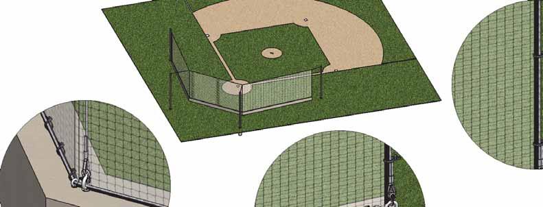
2 D Baseball Backstopper System Cable Design - 4 Poles Layout Form Project Name: Zip Code: A2/A1 = D C B1/A2 = B2/A1 = C A2 POLE A1 POLE B A2/B2 = B1/A1 = B B2 POLE B1 POLE A Please fill in all dimensions in the circled areas above. Copyright C 2010 Aluminum Athletic Equipment Co. B2/B1 = DESCRIPTION: NOTE: MODEL: DWN. BY: N.R. CAD FILE: Aluminum Athletic Equipment 1000 Enterprise Drive, Royersford, PA Toll Free: (800) Fax: (610) Baseball Backstopper System - Cable Design 4 Poles Layout Form CATEGORY: CUSTOMER BBS-30-CD_12 (Big Bend CC) DATE: 2/8/16 DWG. NO. A

3
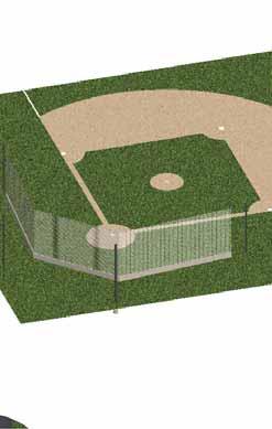
4 PRIOR TO INSTALLATION 1. Check local codes to verify if a Professional Engineer wet stamp is required in your state by a licensed engineer within the state. If so, please contact AAE to assist in this process. 2. Proper location for placement of your cable designed tensioned system should be marked off and a local 1 call should be made and all utilities marked prior to excavation. Use AAE S Layout Form labeled DWG. NO. BBS-CD/ to provide the required distances of poles and help verify that the system is properly designed and there are no changes needed. Center system off the home plate and the pitcher s mound. Consult architect s drawings for proper footing locations and location with respect to the backstop wall. 3. Prior to installing system all soil types and compactions should be considered to meet minimum requirements. 4. Please call AAE and discuss prior to purchasing a system and to verify this system is proper for your project. INSTALLING FOUNDATION TEMPLATES 1. If net is being installed over top a wall AAE should be made aware to accommodate the proper hardware to install. Also if attaching to the top of a fence custom hardware will be needed. 2. Locate proper location for placement of. Center system off the homeplate and the pitcher s mound. Consult architect s drawings for proper foundation locations and location with respect to the wall. Outside 1 ST BASE & 3 RD BASE line poles should be aligned with the wall or fence in order for the net to fall at the interescting point below the Upper Main Tension Cable. 3. AAE does not recommend use of a Sonotube with this products installation, however galvanized steel corrugated is acceptable. 4. Install per DWG. NO. BBS-CD/ and follow engineered layout of rebar. 5. As the concrete cures, constantly check that the top templates are plumb and the threaded studs are level with at least 8 of threaded stud above the top of concrete. 6. Build wall according to architect s specifications. 7. Allow ample time (4-5 days) for concrete to set before erecting poles and tensioning system. Page 1 of 5
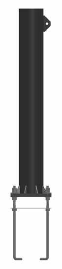
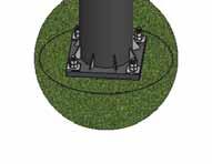
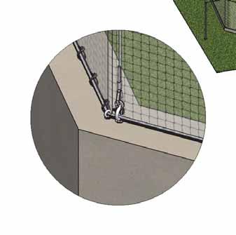
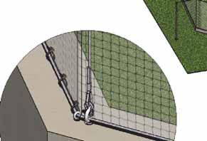
5 POLE ERECTION: 1. Refer to DWG. NO. BBS-CD/ & BBS-CD/ for referencing with the following steps. 2. Once footings have cured, a crane will be required to position the 31 and 35 long poles. Pole weights vary from 1500lbs. to 2000lbs. 3. Make sure to check leveling nuts and verify that they are positioned no more than 2 above the concrete foundation prior to positioning. 4. IMPORTANT! When positioning pole mounting plates over four (4) j-bolts, make sure not to damage j-bolt threads, which could cause irreversible damage. 5. The 31 height poles (A1 & A2) are to be positioned on the outer foundations 1 st & 3 rd base lines, with the welded brackets facing in the direction of home plate (or ultimately the line of the backstop net). 6. The 35 height poles (B1 & B2) are to be positioned on the back corner foundation locations with the brackets facing in the direction of the pitcher s mound. 7. Use 3/8 thick galvanized plate washers with two (2) galvanized steel nuts to properly secure poles to foundation j-bolts. 8. Once poles are leveled and set in proper position a 4,000p.s.i. non-shrink grout should be used to fill the 2 gap between the bottom of the mounting plate and concrete foundation. Give proper time to allow it to set hard. TENSIONING CABLES: 1. Be sure concrete is fully cured before attempting to tension cables. 2. Use a bucket lift to install hardware on pole brackets. 3. Layout the 3/8 diameter Upper Main Tension Cable (longest cable) and locate the center. 4. Measure half the distance of the HOMEPLATE net section length in both directions (Backstop Net B ) and use electrical tape to mark these locations. These are the locations which you will be attaching the 1/4 diameter Vertical Support Cables and the 3/8 diameter Rear Hold-Back Cables. 5. Measure the 1 ST & 3 RD BASE net section lengths from the now marked locations and use electrical tape to mark these locations. These are the locations which you will be attaching the outer Vertical Support Cables. 6. Now you can fasten the end loops of both the 3/8" diameter Hold-Back Cables & 1/4" Vertical Cables to the now marked locations on the 3/8 diameter Upper Main Tension via the anchor shackles. 1/2 (Larger) for the 3/8 Hold-Back Cable and 1/4" (Smaller) for the 1/4" Vertical Cables. Page 2 of 5

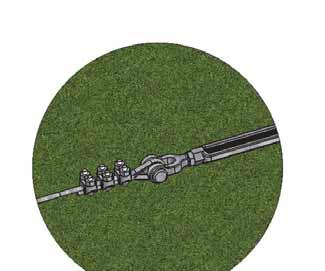
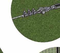
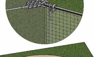
6 7. Make up one end of Upper Main Tension Cable with 1/2 (Larger) galvanized loop thimble (1) and cable clamps (3). The clear vinyl coating on the cable must be cut with a box knife and removed from the cable end in order to allow the cable clamps to work properly. 8. Important: Please note that the orientation of the cable clamps is critical to functioning properly, the Saddle (forged body) must be tightened against the live (long) end of the cable (not the U-bolt)! 9. Attach loop end of the Upper Main Tension Cable to either (just one) the 1 ST BASE or 3 RD BASE line pole s (31 ) bracket via the 1/2 anchor shackle. 10. Then on the opposite 1 ST BASE or 3 RD BASE line pole, use a cable puller and a strap to wrap around the top of the pole and stretch the line out on the puller and temporarily clamp it to the Upper Main Tension Cable (unmade end). 11. Repeat Step No.10 to both 3/8 Hold-Back Cables on their corresponding rear corner poles (B1& B2) and use a cable puller and a strap to wrap around the top of each pole and stretch the line out on the puller and temporarily clamp it to the corresponding cables. 12. At this time you can begin pulling up the Upper Main Tension Cable via the attached cable puller. AAE can provide the finished cable lengths based on information provided in the Layout Form. This will assist in getting as close to the finished cable frame dimension as possible. 13. If not already completed install the 3/8 eyebolts with 3/8 double expansion shields at the four (4) Vertical Cables wall locations (net ends and back corners), which will maintain the proper height of the tensioned net system. 14. Once installed attach the corresponding Vertical Cables bottom loop ends via 1/4" anchor shackles at all four (4) eyebolt locations. 15. Now you can begin pulling up the Hold-Back Cables via the attached cable puller. AAE can provide the finished cable lengths based on information provided in the Layout Form. This will assist in getting as close to the finished cable frame dimension as possible. 16. Once the Vertical Cables are close to being plumb and level, you will need to attach the 7/8 (Large) turnbuckles to the two (2) 35 rear pole s (B1 & B2) welded bracket eyes via 1/2" anchor shackles (make sure turnbuckle is extended at this time to its Page 3 of 5
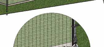
7 full length). 17. Make up the end loops with the 3/8 galvanized thimble and cable clamps. Keep in mind to remove the clear vinyl coating as well as keeping the cable clamps oriented properly as done in Step No Repeat Step No. 17 for the Upper Main Tension Cable (A1 or A2, depending which side you decided to locate the turnbuckle). 19. Once turnbuckles are all attached and cable clamps are tightened, you can now release the cable pullers and straps from the poles. 20. Tension the Upper Main Tension Cable & Hold-Back Cables till the Vertical Cables are tensioned and plumb. ATTACHING BACKSTOP NET: 1. Lay nets on baseball field side and lay according to the proper lengths for the 1 ST, HOME & 3 RD BASE sections. Attach the vertical 1/4" borders every square on each net using the 120lbs. UV treated plastic cable ties. Snip ends off. 2. Using a bucket lift raise the top corner of the 1/4 rope border of the net to the intersection of the 1 ST BASE Vertical Cable & Upper Main Tension Cable. Attach corner using an 8 plastic cable ties 120lbs. strength (larger) UV treated plastic cable ties. Note: Make sure net is on the STANDS side before preparing the next step. 3. Next pull net taught and attach another plastic cable tie to the 1/4 rope border of the net at the intersecting point of the B1 Vertical Cable location and Upper Main Tension Cable. 4. Pull net taught and attach another plastic cable tie to the 1/4 rope border of the net at the intersecting point of the B2 Vertical Cable location and Upper Main Tension Cable. 5. Finally, pull net taught and attach another plastic cable tie to the 1/4 rope border of the net at the intersecting point of the 3 RD BASE Vertical Cable location and Upper Main Tension Cable. 6. Now using the 2-1/2 stainless steel pear clips attach FIRST to the net border and space every 12 on center, THEN attach to the Upper Main Tension Cable. Note: It is a tight fit to get the clips on and very difficult to remove. 7. Attach net borders to Vertical Cables using the 40lbs. strength (smaller) UV treated plastic cable ties every 12 on center. 8. Install intermediate 1/4" stainless steel eyebolts with double expansion shields every 4 on center (space equally between 3/8 eyebolts for Vertical Cables and then run the bottom 1/4" wall cable through the eyes and make up cable and tension turnbuckle at one end. 9. Attach bottom net border to Wall Cable using the 40lbs. strength (smaller) UV Page 4 of 5
8 treated plastic cable ties every 12 on center. 10. Inspect system and tighten as needed. MAINTENANCE AND USE: 1. The net and system are engineered to withstand heavy winds. Plastic cable ties are rated to break in excess winds to save the system. Occasional replacement of clips may be necessary. Please contact AAE to purchase proper load rated cable ties. 2. Occasional inspection is needed to keep system in proper tension. Turnbuckles may need to be re-tensioned if they come loose. 3. Please contact AAE with any questions. FOR TECHNICAL ASSISTANCE, CALL K:\AAE Data\PDF Files\Z-Product Instructions & Parts Lists\BallStopper Systems\BBS-30-CD_12 Assembly Instructions.doc Copyright 2001 Aluminum Athletic Equipment Co. Page 5 of 5
SECTION CHAIN LINK FENCING AND GATES AND SOFTBALL BACKSTOP
 1 1 1 0 1 0 1 0 1 SECTION 1 1 CHAIN LINK FENCING AND GATES AND SOFTBALL BACKSTOP BASED ON DFD MASTER SPECIFICATION DATED /01/ P A R T 1 - G E N E R A L SCOPE The work under this section shall consist of
Installation Instructions
 Column & Beam Units with Debris Netting Installation Instructions Laminated Wood Systems, Inc. Seward, Nebraska 800-949-3526 2015 LWS, INC. AVR-NET INSTALL 05-12-16 AVR Installation Notes 1 Safety The
PART MATERIALS. Section Fencing Materials. Description
 PART 03000 - MATERIALS Section 03010 - Fencing Materials Description 03010.00 Scope - This section consists of the test requirements, specifications and tolerances for barbed wire, woven wire and chain
Section 808. FENCING
 808.01 Section 808. FENCING 808.01. Description. This work consists of providing and erecting, or moving existing, woven wire fence, temporary fence, protective fence, chain link fence, high-tensile wire
WAL-MART SUPERCENTER # ; Milwaukie, OR: SPECIFICATIONS. Revisions to Specification Fence
 MILWAUKIE OR #3144-00 ADDENDUM #5 NARRATIVE: 11-08-12 WAL-MART SUPERCENTER #3144-00; Milwaukie, OR: SPECIFICATIONS SPECIFICATIONS Revisions to Specification 02822 Fence Spec division 02822 has been revised
ASSEMBLY INSTRUCTIONS FOR 2B3004 DELUXE EURO CLUB SOCCER GOAL
 Most Kwik Goal products carry a Lifetime Guarantee. For details or claims, visit kwikgoal.com or contact customer service at 1-800-531-4252. ASSEMBLY INSTRUCTIONS FOR 2B3004 DELUXE EURO CLUB SOCCER GOAL
May 14, Installation Manual
 May 14, 2012 Installation Manual Contents MAG TRACKER Components...1 Mount Installation...7 Module Installation & Grounding...11 Maintenance...14 Warranty......14 Contact Information......14 May 14, 2012
FOR PROFESSIONAL GARAGE DOOR INSTALLERS
 Composite Garage Doors Installation Instructions FOR PROFESSIONAL GARAGE DOOR INSTALLERS Tools required Screwdriver Claw Hammer Locking Pliers Power Drill Level with a 3/32" Drill Bit Utility Knife 9/16",
Project: # Solano Community College District
 ADDENDUM #02 Project: #16 007 Solano Community College District Horticulture Site Improvements Date: April 26, 2016 The following clarifications are provided based on questions received or changes in District
The Festival Assembly Instructions
 The Festival Assembly Instructions Toll Free: 866.768.8465 Hours: 9-5 Monday-Friday EST www.homeplacestructures.com Package ships as shown CONTACT INFORMATION: HomePlace Structures 301 Commerce Drive New
Elements Pole Mounting System
 Elements Pole Mounting System Installation Manual www.peavey.com Elements Pole Mounting System Installation Manual The Elements Pole Mounting System is a simple and straightforward pole mounting solution
5/16" Flange nut. Bolt Keeper Plate (8" Sq. SYS.) (3) 1/2" x 3" Hex head connector zinc plated bolt w/ washers and nut. Anchor 3" sq. 7 Ga.
 (3) 1/2 x 3 Hex head connector zinc plated bolt w/ washers and nut. Anchor 3 sq. 7 Ga.") 2 1/2" x 2 1/2" x 10 Ga. 6" 5" 4" Variable Slipbase (8" Sq. SYS.) 5/16 Corner Bolt W/ nut 5/16" Flange nut Stub Insert (8" Sq. SYS.) Bolt Keeper Plate (8" Sq. SYS.) (3) 1/2" x 3" Hex head connector zinc
2 1/2" x 2 1/2" x 10 Ga. 6" 5" 4" Variable Slipbase (8" Sq. SYS.) 5/16 Corner Bolt W/ nut 5/16" Flange nut Stub Insert (8" Sq. SYS.) Bolt Keeper Plate (8" Sq. SYS.) (3) 1/2" x 3" Hex head connector zinc
Item 550 Chain Link Fence
 Item Chain Link Fence 1. DESCRIPTION 2. MATERIALS Furnish, install, remove, repair, or replace chain link fence and gates. Furnish certification from the chain link fence materials manufacturer stating
TS-20KD-1010 LOW PROFILE CARGO SCALE INSTALLATION GUIDE
 TS-20KD-1010 LOW PROFILE CARGO SCALE INSTALLATION GUIDE Triner Scale & Mfg. Co., Inc. 8411 Hacks Cross Rd. Olive Branch, MS 38654 Phone: 800-238-0152 Fax: 662-809-2386 Description The Triner Scale Model
Installation Instructions
 Installation Instructions For Models: Model Number / Description File Name 1540 Classic Series P-Lam Toilet Partitions 1540.pdf 1 INSTALLATION INSTRUCTIONS LAMINATED PLASTIC TOILET PARTITIONS 1540 Classic
Model #SH & CH SH Pine CH Naturaline
 Model #SH304-101 & CH304-101 Assembly Manual SH304-101 Pine CH304-101 Naturaline Component Parts A 2 ea. Angled Rail - 2 x 4 x 107-1/8" B 1 ea. Center Angled Rail - 2 x 4 x 107-1/8" C 9 ea. Rock Board
A 1 Vertical Pole I 1 BA47/47A/47P Backboard (2 req d on Model BA872)
") Instruction Manual BA871, BA872 Ultimate Playground Basketball System Instructions Customer Service (800) 247-7668 P A R T S L I S T Item Qty Description Item Qty Description A 1 Vertical Pole I 1 BA47/47A/47P
Instruction Manual BA871, BA872 Ultimate Playground Basketball System Instructions Customer Service (800) 247-7668 P A R T S L I S T Item Qty Description Item Qty Description A 1 Vertical Pole I 1 BA47/47A/47P
Mounting Instructions Item No.: xxx
 Mounting Instructions Item No.: 271.92.xxx Wall-Beds 1 General Notes For vertical folding beds Successful and safe installation of Bed-Lift and construction of casework requires a professional skill level
Soma Wind Generators
 Soma Wind Generators 19.5M WINH TOWER INSTALLATION MANUAL ERTIFIED to AS4100 Steel Structures ode AS3995 (1994) Design of Steel Lattice Towers and Masts AS1170.2 (1989) SAA Wind Loading ode Manufactured
GrowSpan Series 500 Roll-Up Ends
 GrowSpan Series 500 Roll-Up Ends Photo may show a different but similar model. Doorframe materials are not included. 2016 Growers Supply All Rights Reserved. Reproduction is prohibited without permission.
400A 40113V, 401A 40120V, & 401AL 40120VL ALUMINUM VERTICAL 4000 LB LIFT INCLUDES SCREW LEG ASSEMBLY INSTRUCTIONS
 12/11/07 PAGE 1 OF 12 400A 40113V, 401A 40120V, & 401AL 40120VL ALUMINUM VERTICAL 4000 LB LIFT INCLUDES SCREW LEG ASSEMBLY INSTRUCTIONS Thank you for purchasing our product! *Please read these instructions
Installation Guide. Capped Cellular PVC Fencing. Table of Contents. Storage and Handling Tools Needed Fence Layout and Locating Posts
 Capped Cellular PVC Fencing Installation Guide Table of Contents Storage and Handling Tools Needed Fence Layout and Locating Posts Installation instructions 4 x 4 Over Sleeve Post - 3.5 Rail Privacy Shadowbox
FENCE INSTALLATION GUIDE 8 HIGH WALLS
 FENCE INSTALLATION GUIDE 8 HIGH WALLS 1.866.648.9336 www.simtekfence.com INSTALLATION GUIDE These instructions are designed to assist both professional installers and do-it-yourselfers of SimTek decorative
Edgerail Aluminum Bridge Railing System Specification & Installation Instructions
 Edgerail System Specification & Installation Instructions Hill & Smith, Inc 1000 Buckeye Park Road Columbus, Ohio 43207 Tel: 614-340-6294 Fax: 614-340-6296 www.hillandsmith.com Section A System Specification
BBULTRA Basketball Tower Installation
 Ph: 1300 500 314 Basketball Tower Installation Thank you for your purchase of the Ultra adjustable Basketball system. To ensure that our equipment will provide years of use to you, we are including this
Installation Instructions
 FORD 20K Industry Standard Rail Custom Mounting Kit #2760 Gross Trailer Weight (Maximum)...20,000 lbs. Vertical Load Weight (Max. Pin Weight)...5,000 lbs. SYSTEM TOW CAPACITY Please note, in order to determine
CertainTeed INSTALLATION GUIDE SIMTEK FENCE PRODUCTS. Fence Installation Guide 3', 4' & 6' High
 CertainTeed INSTALLATION GUIDE SIMTEK FENCE PRODUCTS Fence Installation Guide 3', 4' & 6' High INSTALLATION GUIDE These instructions are designed to assist both professional installers and do-it-yourselfers
Post & Rail. Includes: Crossbuck, 2-Rail, 3-Rail and 4-Rail POST SUPPORT OPTIONS
 Post & Rail Includes: Crossbuck, 2-Rail, 3-Rail and 4-Rail STAGGER RAIL ENDS FOR GREATER STRENGTH ALLOW 1-1/2" GAP ON HINGE SIDE OF GATE AND 1-1/4" ON LATCH SIDE OF GATE HARDWARE DIG HOLES 30" MINIMUM
Rolling Curtain door Manual
 Rolling Curtain door Manual Installation Maintenance parts Model 944 PHONE 800 448 8979 FAX 800 236 8722 website www.tracrite.com EMAIL tr@tracrite.com ADDRESS 216 Wilburn Road Sun Prairie, WI 53590 This
6 1/2 x 6 1/2 Wood Grain Flat Top Pergola
 / x / Wood Grain Flat Top Pergola A S S E M B LY G U I D E Models: Lakewood OPTIONAL ACCESSORY Bolt Down Bracket Kit V.-09 Ta b l e o f Co n t e n t s The PAGE Introduction & Overview.......................................................
TELESCOPIC GATE MANUFACTURING AND INSTALLATION MANUAL.
 TELESCOPIC GATE MANUFACTURING AND INSTALLATION MANUAL. Telescopic gates have been manufactured for many years essentially in the same way they are largely today. In recent years hardware suppliers have
Assembly Instructions
 InTandem Table System November 20 InTandem Table System - Worksurface #4 x/" 4 wood screw power beam Tools Provided T-0 Extended Torx Driver T-25 Torx Driver Additional Tools Required Soft protective
Installation and Assembly - Universal Articulating Swivel Double-Arm for 42" - 60" Plasma Screens
 Installation and Assembly - Universal Articulating Swivel Double-Arm for 42" - 60" Plasma Screens Models: PLAV 70-UNL, PLAV 70-UNL-S PLAV 70-UNLP, PLAV 70-UNLP-S R This product is UL Listed. It must be
Installation Instructions
 DODGE RAM 2500 20K Industry Standard SuperRail Custom Mounting Kit #2336 Gross Trailer Weight (Maximum)...20,000 lbs. Vertical Load Weight (Max. Pin Weight)...5,000 lbs. SYSTEM TOW CAPACITY Please note,
Installation Instructions. Tools Needed. Tape measure. Level. Shovel or Post hole digger. Concrete. Drill. Stakes. Mallet or hammer.
 Installation Guide EcoStone Fence 1330 West 400 North Orem, UT 84057 Toll Free 1.866.648.9336 Tel. 1.801.655.5236 Fax 1.801.655.5240 www.ecostonefence.com Installation Instructions Introduction. These
6 1/2 x 6 1/2 Flat Top Pergola
 6 / x 6 / Flat Top Pergola A S S E M B L Y G U I D E Models: Portland, Liberty O P T I O N A L A C C E S S O R Y Bolt Down Bracket Kit V.-0506 Ta b l e o f Co n t e n t s PAGE The Introduction & Overview......................................................
Installation Instructions
 CHEVY / GMC 16K Industry Standard Rail Custom Mounting Kit #2730 Gross Trailer Weight (Maximum)...16,000 lbs. Vertical Load Weight (Max. Pin Weight)...4,000 lbs. SYSTEM TOW CAPACITY Please note, in order
Directions for the 25' Jr Batting Cage & Frame
 Directions for the 25' Jr Batting Cage & Frame Parts Qty Part Description 1 6 Upper corners of the arch (with hex bolts) 2 6 Bent pipe for arch feet 3 6 Pipe with no swedge (2 per horizontal arch) 4 12
PLAY HOUSE IMPORTANT
 IMPORTANT Page 1 PLEASE READ THESE INSTRUCTIONS BEFORE COMMENCING ASSEMBLY. All equipment must be installed in accordance with these instructions. Check your shipment against Bill of Lading and Parts list.
ClearSpan End Frame Kit 26' Wide x 12' High
 ClearSpan End Frame Kit 26' Wide x 12' High Diagram shows the end frame kit for an end wall without a door. (Door and end panel are purchased separately.) Rafter and struts shown in the above diagram are
M2 Antenna Systems, Inc. Model No: 20M5LD
 M2 Antenna Systems, Inc. Model No: 20M5LD SPECIFICATIONS: Model... 20M5LD Frequency Range... 14.0 14.350 MHz *Gain (Full Band)... 10.2 dbi Typical Front to back... 23 db Typical Beamwidth... E=50 / H=66
Installation Instructions
 TOYOTA 16K Industry Standard Rail Custom Mounting Kit #2748 Gross Trailer Weight (Maximum)...16,000 lbs. Vertical Load Weight (Max. Pin Weight)...4,000 lbs. SYSTEM TOW CAPACITY Please note, in order to
12, 14 & 16 Wide Enclosure Assembly Guide
 www.rmfiberglass.com 12, 14 & 16 Wide Enclosure Assembly Guide RM Products Ltd 1-800-363-0867 www.rmfiberglass.com Table of Contents 1. Handling and Storage page 3 to 5 2. Parts and Tools List page 7 3.
UPM 6X. UPM 6X Standard stock Tee socket sized for 5" schedule 40 or 80 Pipe. Page 1 of 8
 Page 1 of 8 UPM 6X A. TEE SOCKET: 6 O.D. PIPE SOCKET TO FIT OVER 5 SCHEDULE 40 OR 80 STEEL PIPE B. CROSS PIECE: 2 X 2 X 1/8, LENGTH DEPENDENT ON MODULE USED, SQ. TUBE 2 PLACES C. LONGITUDINAL: 2 X 2 X
SB-WM-ART2-L-BL SB-WM-ART2-XL-BL
 SB-WM-ART2-L-BL SB-WM-ART2-XL-BL Weatherproof Universal Dual-Arm Articulating Mount for Large TVs INSTALLATION MANUAL WARNING The maximum weight of this wall mount is 150 lbs (68.04 kg). Use with heavier
Kwik-Lock. Installation Instructions. Attention Dealers: Please give this owners manual to the customer when the product is delivered.
 Serving the Truck & Trailer Industry Since 1944 Installation Instructions Attention Dealers: Please give this owners manual to the customer when the product is delivered. Call 800-535-9545 www.aeroindustries.com
10 x 10 Arch Top Pergola
 0 x 0 Arch Top Pergola I N S T A L L A T I O N G U I D E O P T I O N A L A C C E S S O R I E S Privacy Fence Panel System ( Panels & Middle Post Included) Bolt Down Bracket Kit (Set of ) Additional Shade
FORD #2228. Gross Trailer Weight (Maximum)...24,000 lbs. Vertical Load Weight (Max. Pin Weight)...6,000 lbs. SYSTEM TOW CAPACITY
...24,000 lbs. Vertical Load Weight (Max. Pin Weight)...6,000 lbs. SYSTEM TOW CAPACITY") FORD 24K Industry Standard Rail Heavy Duty Custom Mounting Kit #2228 Gross Trailer Weight (Maximum)...24,000 lbs. Vertical Load Weight (Max. Pin Weight)...6,000 lbs. SYSTEM TOW CAPACITY Please note, in
FORD 24K Industry Standard Rail Heavy Duty Custom Mounting Kit #2228 Gross Trailer Weight (Maximum)...24,000 lbs. Vertical Load Weight (Max. Pin Weight)...6,000 lbs. SYSTEM TOW CAPACITY Please note, in
Spring Loaded SCREEN-PRO. All Season Roll-Up Doors IN-JAMB MOUNTING METHOD INSTALLATION INSTRUCTIONS READ THIS FIRST
 Spring Loaded SCREEN-PRO All Season Roll-Up Doors IN-JAMB MOUNTING METHOD INSTALLATION INSTRUCTIONS READ THIS FIRST Carefully examine the crate(s) for damage before opening. If the carton is damaged, immediately
NX7 SERIES 5-1/2 HANDRAIL
 STORAGE & HANDLING The handrails are shipped unassembled. Upon receipt, immediately check all material for any damage that may have occurred in transit and verify that all of the items and quantities are
Chapter 23. Garage Construction
 Chapter 23. Garage Construction 23.1 ESTABLISHING CHALK LINES 23.2 MEASURING AND CUTTING WALL PLATES 23.3 MARKING WINDOW & DOOR LOCATIONS ON EXTERIOR WALL PLATES 23.4 MARKING STUDS ON EXTERIOR WALL PLATES
Installation Instructions
 CHEVY / GMC 24K Industry Standard Rail Heavy Duty Custom Mounting Kit #2226 Gross Trailer Weight (Maximum)...24,000 lbs. Vertical Load Weight (Max. Pin Weight)...6,000 lbs. SYSTEM TOW CAPACITY Please note,
SECTION 19: Endwood Fusion Welded Gate Installation Guide
 SECTION 19: Endwood Fusion Welded Gate Installation Guide ASSEMBLY AND INSTALLATION FOR: Fusion Welded Gates Gate Frame with Full Size Pickets Privacy & Board on Board California & Shadowbox Gate width
ClearSpan PolyMax Windbreak Wall
 ClearSpan PolyMax Windbreak Wall Photo may show a different but similar model. 2007 ClearSpan All Rights Reserved. Reproduction is prohibited without permission. Revision date: April 2007ldg STK# DIMENSIONS
Thank you for purchasing our product! *Please read these instructions and follow them step by step.*
 07/07/08.rev1 PAGE 1 OF 11 601AL VERTICAL 60120VL LIFT W/CHAIN DRIVE WINCH Thank you for purchasing our product! *Please read these instructions and follow them step by step.* Step 1. Separate and group
Installation Instructions
 FORD 20K Industry Standard Rail Custom Mounting Kit #2738 Gross Trailer Weight (Maximum)...20,000 lbs. Vertical Load Weight (Max. Pin Weight)...5,000 lbs. SYSTEM TOW CAPACITY Please note, in order to determine
INSTALLATION INSTRUCTIONS 3"/4 BENT END SIDEBARS FORD F-150 SUPERCREW PART # DZ /DZ
 INSTALLATION INSTRUCTIONS 09-12 FORD F-150 SUPERCREW PART # DZ 372697/DZ 372699 PARTS LIST: 1 Driver/Left Sidebar 4 1/2 Lock Washers 1 Sidebar 4 12mm x 32mm OD x 3mm Flat Washers 1 Driver/Left Mounting
Gared Pro Portable Backstop
 Models: 5016, 5017, & 5018 Installation, Operation and Maintenance Instructions Please read all instructions before attempting installation or operation of these units PUBLICATION NO. 551754436 SAVE THESE
ASSEMBLY GUIDE. Barcelona Pergola. 12 X16 (365CMx487CM) VER /01/19
 VER /01/19") ASSEMBLY GUIDE Barcelona Pergola 12 X16 (365CMx487CM) VER 1.9 04/01/19 GETTING STARTED First off, allow us to say thank you for the investment you have made in our fine pergola. This pergola is designed
ASSEMBLY GUIDE Barcelona Pergola 12 X16 (365CMx487CM) VER 1.9 04/01/19 GETTING STARTED First off, allow us to say thank you for the investment you have made in our fine pergola. This pergola is designed
GrowSpan Round Premium High Tunnels
 GrowSpan Round Premium High Tunnels Photo may show a different but similar model. 2016 Growers Supply All Rights Reserved. Reproduction is prohibited without permission. STK# PB01680R4 PB01690R4 DIMENSIONS
Instruction Sheet For: SCM-2
 Instruction Sheet For: SCM-2 For more information, please contact us at: 345 Log Canoe Circle, Stevensville, Maryland 2666 Toll Free: 877.28.269 Phone: 40.643.6390 Fax: 40.643.665 www.videomount.com 27
Installation Instructions for. Handrail Component System
 Handrail STEP-BY-STEP Installation Instructions for Handrail Component System Rise in Inches Run in Inches 8 8.5 9 9.5 10 10.5 11 11.5 12 12.5 13 13.5 14 14.5 15 8.5 47 45 43 42 40 39 38 36 35 34 33 32
Melamine Plastic Laminate. Toilet Partition Installation Manual
 Melamine Plastic Laminate Toilet Partition Installation Manual PHONE: FAX: 1-866-317-2786 ATTENTION DO NOT MIX FASTENER PACKS EACH FASTENER PACK HAS THE NECESSARY BOLTS, BARRELS AND SCREWS TO INSTALL THE
1. Layout. Step 1. Step 2. Step 3. Fig. 1
 1-3/8 Panel Clamp Tools You Will Need: Tape Measure, Mason s String, Stakes, Hole Digger, Shovel, Level, Wheelbarrow, Wrenches or Adjustable Wrench, Hacksaw, Pliers, Cutting Pliers, Fence Stretcher and
Open shipping crate and separate all of the different parts. Over The Top Shelters LLC
 ASSEMBLY INSTRUCTIONS FOR MODEL SH122110GN and SH122110GY Open shipping crate and separate all of the different parts. Count each part and match up with parts list. Shortages or damaged parts should be
Horizontal Cable Systems
 ALUMINUM RAILING INSTALLATION INSTRUCTIONS v2012 orizontal Cable Systems 1) Check Contents Of Packages: Verify that all parts have arrived and that they match the packing list. 1A) Coastal applications:
Installation Instructions
 CHEVY / GMC 20K Industry Standard Rail Custom Mounting Kit #2724 Gross Trailer Weight (Maximum)...20,000 lbs. Vertical Load Weight (Max. Pin Weight)...5,000 lbs. SYSTEM TOW CAPACITY Please note, in order
FORPARK AUSTRALIA
 FORPARK PRICE LIST AS AT 10/19/2018 Contents Prepare the site... 3 Equipment required for installation... 3 Fasteners... 4 Argonaut... 5 Carousel - With Rails/no rails... 6 Concord... 7 Cyclone... 8 Flying
SECTION CHAIN LINK FENCING AND GATES
 PART 1 GENERAL 1.01 SCOPE OF WORK A. The Contractor shall furnish and install all materials, labor, equipment and incidentals required to provide chain link fencing and gates as Shown on the Contract Drawings
Safe and secure Dero
 B I K E D E P OT Safe and secure Whether the project is at a transit station, university campus, or residential building, the Bike Depot s modular design lets customers easily build out to meet their space
FRAMELESS GLASS FENCING DIY GUIDE
 FRAMELESS GLASS FENCING SITE MEASURE 1. Planning is the first step of any successful project. 2. We have a large range of sizes to allow for varying site requirements. 3. Simply decide where you would
ClearSpan PolyMax Windbreak Wall
 ClearSpan PolyMax Windbreak Wall Photo may show a different but similar model. 2007 ClearSpan All Rights Reserved. Reproduction is prohibited without permission. Revision date: February 2007ldg STK# DIMENSIONS
Installation and Assembly - Universal Articulating Swivel Double-Arm for 42" - 60" Plasma Screens
 Installation and Assembly - Universal Articulating Swivel Double-Arm for 42" - 60" Plasma Screens Models: PLAV 70-UNL, PLAV 70-UNL-S PLAV 70-UNLP, PLAV 70-UNLP-S R This product is UL Listed. It must be
DX-TVMLPTB03. Low-Profile TV Wall Mount ASSEMBLY GUIDE. For either wood-stud or concrete wall installations
 ASSEMBLY GUIDE DX-TVMLPTB03 Low-Profile TV Wall Mount For either wood-stud or concrete wall installations Safety information and specifications...2 Tools needed...........................3 Package contents......................3
Manual for Shelter W3,5xL8,0xH3,8m
 Manual for Shelter W3,5xL8,0xH3,8m 22-11-2016 Congratulations on your purchase of our instant shelter. This unit is a combination of excellent manufacturing and design. It is comprised of a rigid frame
KOLO SHELTER Installation Instructions Parts List
 Parts List Roof Cap Rafter Upright Polycarbonate Polycarbonate Drop Polycarbonate Flange Center Weldment (Short length shown above) Polycarbonate Edge Bolt.25 x 6.5 Bolt.625 x 7.5 Threaded Rod.75 x 14
Large Wood Windmill Assembly Instructions
 CROW S NEST (TOP VIEW) TOWER (SIDE VIEW) 0 QTY 2 2 ITEM QTY 2 QTY QTY 8 QTY 8 QTY 4 TOP TOP TOP 47 9 QTY 4 QTY 4 QTY 4 QTY 4 QTY 4 ITEM 6 ITEM 7 ITEM 8 ITEM 3 ITEM 9 ITEM 4 ITEM 2 ITEM 5 47 Leg QTY 4 42.5
GlideRite Retractable Cover System For HotSpring & Tiger River Spas (except Classic & pre-2000 Landmark Spas)
") List of Contents Quantity Description 12 #10 x 1 ½ Flat Head Phillips Screw (see pg. 2) 2 #10 x ½ Pan Head Phillips Screw (see pg. 2) 8 ¼ x 2 ½ Lag Bolt (see pg. 2) 7 ¼ 20 x 5 / 8 Hex Head Bolt (see pg.
List of Contents Quantity Description 12 #10 x 1 ½ Flat Head Phillips Screw (see pg. 2) 2 #10 x ½ Pan Head Phillips Screw (see pg. 2) 8 ¼ x 2 ½ Lag Bolt (see pg. 2) 7 ¼ 20 x 5 / 8 Hex Head Bolt (see pg.
S48-L12-SC AND G48-L12-GC STEEL PORTA-DOCK S82 SC 6 X 12 PLATFORM AND G82 GC 6 X 12 PLATFORM
 PAGE 1 OF 6 PORTA-DOCK, INC. S48-L12-SC AND G48-L12-GC STEEL PORTA-DOCK S82 SC 6 X 12 PLATFORM AND G82 GC 6 X 12 PLATFORM Thank you for purchasing our product! *Please read these instructions and follow
PowerLock. Installation Instructions. Attention Dealers: Please give this owners manual to the customer when the product is delivered.
 Serving the Truck & Trailer Industry Since 1944 FOR Attention Dealers: Please give this owners manual to the customer when the product is delivered. Call 800-535-9545 www.aeroindustries.com Indianapolis,
Gared Pro-S Portable Backstop
 Models: 9616 & 9618 Installation, Operation and Maintenance Instructions Please read all instructions before attempting installation or operation of these units SAVE THESE INSTRUCTIONS FOR FUTURE USE PUBLICATION
INSTALLATION INSTRUCTIONS
 INSTALLATION INSTRUCTIONS LAMINATED P LASTIC TOILET PArTITIONS 1540 ClassicSeries with Options IMPORTANT: Storage and Handling Information on last page. For faster, easier installation, please review these
ULTRA SPACE SAVER Installation Instructions
 Installation Instructions The Ultra Space Saver has several steps for installation. Note that the single and double sided setups and parts are different. Make sure you follow the instructions according
How-To-build guide carport
 How-To-build guide carport What you can build using this guide This guide will show you how to build a free-standing, open-sided single carport. Before you begin building Contact your local territorial
Clean-Roll. Installation Manual. [Revision: January 10, 2013, , Rytec Corporation 2004]
![Clean-Roll. Installation Manual. [Revision: January 10, 2013, , Rytec Corporation 2004]](/thumbs/78/77459232.jpg "Clean-Roll. Installation Manual. [Revision: January 10, 2013, , Rytec Corporation 2004]") Clean-Roll Installation Manual [Revision: January 10, 2013, 0715005, Rytec Corporation 2004] TABLE OF CONTENTS PAGE INTRODUCTION.............................................1 UL NON-COMPLIANCE FOR SANITARY
Clean-Roll Installation Manual [Revision: January 10, 2013, 0715005, Rytec Corporation 2004] TABLE OF CONTENTS PAGE INTRODUCTION.............................................1 UL NON-COMPLIANCE FOR SANITARY
IMPORTANT GOAL SAFETY INSTRUCTIONS READ CAREFULLY
 IMPORTANT GOAL SAFETY INSTRUCTIONS READ CAREFULLY 1. Check for structural integrity and proper connecting hardware before every use. Replace damaged or missing parts or fasteners immediately. 2. Safety/Warning
M2 Antenna Systems, Inc. Model No: 20M6-125
 M2 Antenna Systems, Inc. Model No: 20M6-125 SPECIFICATIONS: Model... 20M6-125 Frequency Range... 14.0 14.350 MHz *Gain, (FS) / Over gnd... 11.19dBi / 16.6dBi @70 Front to back... 25 db Typical Beamwidth...
Al Keller s Inexpensive Backyard Greenhouse Plans
 Al Keller s Inexpensive Backyard Greenhouse Plans There are many ways to construct low cost greenhouses for your property. This is just one man s design, using easily obtainable and fairly inexpensive
No No No
 INSTALLATION, ASSEMBLY & MAINTENANCE MANUAL BASEBALL BACKSTOP No. 331025 No. 331036 No. 331039 No. 331025 No. 331036 No. 331039 INSTALLER NOTE: Upon completion of the installation/assembly of this baseball
CEILING-MOUNTED MONORAIL ANCHOR TRACK SYSTEM Assembly and Operation Instruction Manual
 CEILING-MOUNTED MONORAIL ANCHOR TRACK SYSTEM Assembly and Operation Instruction Manual This manual is for various mounting types and plain and trussed track profiles. ISO 9001:2008 Registered Manual 103-0075
6 1/2 x 6 1/2 Wood Grain Flat Top Pergola
 / x / Wood Grain Flat Top Pergola A S S E M B LY G U I D E Models: Lakewood OPTIONAL ACCESSORY Bolt Down Bracket Kit V.- Ta b l e o f Co n t e n t s The PAGE Introduction & Overview.......................................................
ASSEMBLY INSTRUCTIONS
 Universal Top-of-Pole Mount 8 Modules (UTPM8) Module Type G ASSEMBLY INSTRUCTIONS step-by-step assembly and installation Version 1, Rev A PCN 022714-1 Universal Top-of-Pole Mount 8 Modules (UTPM8) for
ClearSpan 38' Wide Aircraft Hangar
 ClearSpan 38' Wide Aircraft Hangar Photo may show a model of a different length. 2008 ClearSpan All Rights Reserved. Reproduction is prohibited without permission. STK# DIMENSIONS 107556 38' W x 15' H
C L A S S I C. Deluxe. Snow Thrower Cab. Assembly and Care Instructions
 C L A S S I C Deluxe Snow Thrower Cab Assembly and Care Instructions Deluxe Snow Thrower Cab Assembly and Care Instructions Before you begin please unpack the carton and check that you have all your parts.
Installation Instructions for Solar Snow Pad (SSP-T-3)
") Installation Instructions for Solar Snow Pad (SSP-T-3) Warning- Do not use this product on solar arrays where the calculated array snow loads exceed 50 pounds per square foot (psf). Most solar panels are
Installation Instructions for Solar Snow Pad (SSP-T-3) Warning- Do not use this product on solar arrays where the calculated array snow loads exceed 50 pounds per square foot (psf). Most solar panels are
Before returning this product to the store of purchase
 Before returning this product to the store of purchase Contact Dee Zee if you experience the following problems: Missing Parts Installation Problems/Questions Warranty Questions 1.800.779.2102 Hours of
ClearSpan End Frame Kit 30' Wide x 11' High
 ClearSpan End Frame Kit 30' Wide x 11' High Diagram shows the end frame kit for an end wall without a door. (Door and end panel are purchased separately.) Rafter and mounting feet shown in the above diagram
KO LO SH E LT E R. High Capacity and Flexibility
 KO LO SH E LT E R High Capacity and Flexibility The unique styling of our redesigned Dero Kolo Shelter will help beautify your facility and provide secure, covered bike parking for cyclists. The Kolo is
1. VERIFY ALL COMPONENTS
 R INSTALLATION INSTRUCTIONS RAGNAR+ODEN FACE MOUNT, BYPASSING. VERIFY ALL COMPONENTS BASE KIT Track stand-offs Front trolley kit * Rear trolley kit * Allen keys Track fastener kit - wood - Bottom guide
Technologies, Inc. Installation Instructions for Anchors & Components. Rev PAGE 1 / 11
 Installation Instructions for Anchors & Components PAGE 1 / 11 GROUND ANCHOR INSTALLATION INSTRUCTIONS NOTE: 1) The tensioning bolt can be inserted in the head from either side. 2) In areas of severe cold