KRAMER ELECTRONICS LTD. USER MANUAL MODEL: MODULAR TBUS-1Axl Table Connection Bus. P/N: Rev 3
|
|
|
- Francine Benson
- 5 years ago
- Views:
Transcription
1 KRAMER ELECTRONICS LTD. USER MANUAL MODEL: MODULAR TBUS-1Axl Table Connection Bus P/N: Rev 3
2
3 Contents 1 Introduction 1 2 Getting Started Achieving the Best Performance Glossary 2 3 Overview 3 4 Your TBUS-1Axl Enclosure TBUS-1Axl Optional Inner Frames TBUS-1Axl Accessories Power Socket Options Power Cord Options 9 5 Installing the TBUS-1Axl Assembling the Inner Frame Installing the Inner Frame Cutting an Opening in the Table Inserting the TBUS-1Axl through the Cut Out Opening Connecting the Cables Inserting the Pass-through Cables Adjusting the Height of the Inner Frame 18 6 Using the TBUS-1Axl 19 7 Technical Specifications of the Assembled TBUS-1Axl 20 Figures UFigure 1: TBUS-1Axl inside a TableU 3 UFigure 2: TBUS-1Axl Enclosure Top ViewU 4 UFigure 3: TBUS-1Axl Inner Frame (P/N: )U 11 UFigure 4: Installing a Kramer TOOLU 12 UFigure 5: Installing the T-TBLANK TOOL BlankU 12 UFigure 6: T-RC8IR (P/N: )U 13 UFigure 7: RC-8IR Faceplate holestable Connection BusU 13 UFigure 8: Cut out DimensionsU 15 UFigure 9: Inserting TBUS-1Axl into the Prepared OpeningU 16 UFigure 10: Cable Pass-through Insert (P/N: )U 17 UFigure 11: TBUS-1Axl Boardroom InstallationU 19 TBUS-1Axl Contents i
4 1 Introduction Welcome to Kramer Electronics! Since 1981, Kramer Electronics has been providing a world of unique, creative, and affordable solutions to the vast range of problems that confront the video, audio, presentation, and broadcasting professional on a daily basis. In recent years, we have redesigned and upgraded most of our line, making the best even better! Our 1,000-plus different models now appear in 11 groups that are clearly defined by function: GROUP 1: Distribution Amplifiers, GROUP 2: Switchers and Matrix Switchers, GROUP 3: Control Systems, GROUP 4: Format/Standards Converters, GROUP 5: Range Extenders and Repeaters, GROUP 6: Specialty AV Products, GROUP 7: Scan Converters and Scalers, GROUP 8: Cables and Connectors, GROUP 9: Room Connectivity, GROUP 10: Accessories and Rack Adapters and GROUP 11: Sierra Products. Thank you for purchasing the Kramer TBUS-1Axl enclosure, which is ideal for boardrooms, conference and training rooms! i Note that the inner frame, power socket assembly, power cord and other inserts for the TBUS-1Axl enclosure are purchased separately. TBUS-1Axl - Introduction 1
5 2 Getting Started We recommend that you: Unpack the equipment carefully and save the original box and packaging materials for possible future shipment Review the contents of this user manual Use Kramer high-performance high-resolution cables i Go to to check for up-to-date user manuals, a complete list of Kramer wall plates and module connectors, application programs, and to check if firmware upgrades are available (where appropriate). 2.1 Achieving the Best Performance To achieve the best performance: Use only good quality connection cables to avoid interference, deterioration in signal quality due to poor matching, and elevated noise levels (often associated with low quality cables) Avoid interference from neighboring electrical appliances that may adversely influence signal quality Position your Kramer TBUS-1Axl away from moisture, excessive sunlight and dust 2.2 Glossary Inner frame Universal socket Insert The inner frame fits into the TBUS enclosure The Universal socket fits almost all power cords, worldwide The insert is fitted in the inner frame. Go to our Web site to check for a variety of single and dual sized inserts 2 TBUS-1Axl - Getting Started
.")
6 3 Overview The TBUS-1Axl is a modular furniture-mounted connection bus enclosure that is easily installed into a table or podium top. Once assembled, the TBUS-1Axl lets you connect any equipment to the room s presentation system installations via cable access or passive interfaces (see Figure 1). When the cables are not in use, they can be stored inside the unit, covered by the lid and out of sight. In addition, the TBUS-1Axl features: A modular design, letting you tailor the TBUS-1Axl according to your requirements A black anodized or brushed clear aluminum lid with a special opening for cable pass-through, (note, that other customized colors can also be ordered) Height adjustment screw holes to set the inner frame (ordered separately) to the desired height Single or dual power socket openings that are suitable for any of the following power sockets: for the USA, Germany (the Europlug), Belgium- France, Italy, Australia, Israel, South Africa or Universal for use anywhere (see compatibility restrictions in Section 7) Order the power sockets separately from Kramer Electronics Figure 1: TBUS-1Axl inside a Table! Do not place heavy objects on top of the TBUS-1Axl. TBUS-1Axl - Overview 3
7 4 Your TBUS-1Axl Enclosure Figure 2: TBUS-1Axl Enclosure Top View # Feature Function 1 Black Anodized/Brushed Clear Textured Lid Includes an opening for cable pass-through; covers the inner frame, leaving the table surface neat and tidy 2 Outer Rim Fits over the table surface. A protective rubber guard protects the outer rim during shipping. Remove it before installing the unit 3 Enclosure Inserted into the table cut out 4 TOOL Height Adjustment Used for installing Kramer TOOLs Screw Holes 5 Tie Holes Insert the self-locking tie through the holes to fix the passthrough cables to the inside walls of the unit 6 Bracket Slits For attaching the two mounting brackets on opposite sides 7 Rubber Protectors Protect the table surface when mounting the unit and ensure soft tightening to the table underside (one for each clamp) Table Clamping Set 8 Locking Butterfly Screws 9 Mounting Butterfly Screws 10 Mounting Brackets (2 units) 11 Inner Frame Height Adjustment Screw Holes Tighten to lock the mounting butterfly screw (one for each clamp) Tighten to secure the unit to the table surface (one for each clamp) Place in the bracket slits after inserting the enclosure into the table for securing the unit to the table surface (one for each clamp) For adjusting the height of the mounted inner frame 4 TBUS-1Axl - Your TBUS-1Axl Enclosure

 1")
 2 openings for 4 power sockets 2 cable pass-through inserts 2 blank")

8 4.1 TBUS-1Axl Optional Inner Frames The following inner frames can be installed in the TBUS-1Axl enclosure: Inner Frames for TBUS-1A Specifications (define what you can include in this inner frame): T1AF-16 (P/N: ) 1 opening for 1 power socket 2 cable pass-through inserts 4 blank inserts T1AF-26 (P/N: ) 1 opening for 2 power sockets 2 cable pass-through inserts 4 blank inserts T1AF-44 (P/N: ) 2 openings for 4 power sockets 2 cable pass-through inserts 2 blank inserts T1AF-14L (P/N: ) 1 opening for 1 power socket 1 opening for Kramer SI-1VGA / RC-3TB 2 cable pass-through inserts 2 blank inserts TBUS-1Axl - Your TBUS-1Axl Enclosure 5

 1 special panel to fit the Kramer RC-8IR Control Panel into the appropriate frame (P/N 80-000399 or P/N 80-000499 instead of two power sockets)")
 This TOOL blank covers a TOOL opening for the T1AF-1T3 (P/N: 80-005199) and T1AF-14T (P/N: 80-005299) inner frames 6")
9 T1AF-1T3 (P/N: ) 1 opening for 1 power socket 2 openings for 3 Kramer TOOLs T1AF-14T (P/N: ) 1 opening for 1 power socket 1 opening for 1 Kramer TOOL 2 cable pass-through inserts 2 blank inserts i Custom made inner frames can be designed if required. Contact Kramer Electronics for more details. 4.2 TBUS-1Axl Accessories Accessories Inserts Description You can install any wall plate devices as well as any of the single or dual inserts see our Web site for details. T-RC8IR (P/N: ) 1 special panel to fit the Kramer RC-8IR Control Panel into the appropriate frame (P/N or P/N instead of two power sockets) T-2INSERT (P/N: ) The T-2INSERT kit can be installed inside a single power socket opening and includes: 1 single cable pass-through insert 1 dual cable pass-through insert T-TBLANK (P/N: ) This TOOL blank covers a TOOL opening for the T1AF-1T3 (P/N: ) and T1AF-14T (P/N: ) inner frames 6 TBUS-1Axl - Your TBUS-1Axl Enclosure
, Belgium- France, Italy, South")


 Maximum 5A per power outlet Partially compatible (if the polarity is reversed) with plugs")

 Maximum 5A per power outlet Germany and EU:")
10 4.3 Power Socket Options A choice of one or more power sockets per inner frame is available in several versions, including power sockets for the USA, Germany (the Europlug), Belgium- France, Italy, South Africa, Israel and Australia. A Universal socket for general use is also available (see the compatibility restrictions in the table below). The Single Power Socket Assemblies Power Socket Power Specs Power Socket Type Power Specs Type Universal: TS/1U ( ) Fully compatible with power plugs in the UK, India, Italy and Denmark, as well as with the 2-prong Europlug. Power Socket Type V AC, 50/60Hz, 5A Maximum 5A per power outlet Power Specs USA: TS-1US ( ) Maximum 5A per power outlet Partially compatible (if the polarity is reversed) with plugs in China, Switzerland, Israel and the USA. The universal socket does not supply grounding to plugs in Central Europe and France and so you should order country specific sockets instead. Not compatible with South African plugs. Power Socket Power Specs Type Italy: TS-1IT ( ) Maximum 5A per power outlet Germany and EU: TS-1DE ( ) Maximum 5A per power outlet Australia: TS-1AU ( ) Maximum 5A per power outlet Belgium and France: TS-1FR ( ) Maximum 5A per power outlet Israel: TS-1IL ( ) 220V AC, 50/60Hz, 5A Maximum 5A per power outlet South Africa TS-1ZA ( ) Maximum 5A per power outlet TBUS-1Axl - Your TBUS-1Axl Enclosure 7


 Germany and EU: TS-2DE")
 Italy TS-2IT")
 Israel: TS-2IL")
")
11 Dual power sockets are used for TBUS-1Axl with two or four power sockets: Dual Power Socket Assemblies: Power Specs Universal: TS-2U ( ) USA: TS-2US ( ) Germany and EU: TS-2DE ( ) France: TS-2FR ( ) Italy TS-2IT ( ) Australia: TS-2AU ( ) Israel: TS-2IL ( ) 220V AC, 50/60Hz, 5A South Africa: TS-2ZA ( ) 220V AC, 50/60Hz, 5A 8 TBUS-1Axl - Your TBUS-1Axl Enclosure
12 4.4 Power Cord Options You can order any of the following power cords to use with a modular TBUS: Power Cord Type Description P/N 6ft/110V (North America) C-AC/US (110V) ft/125V (Japan) C-AC/JP (125V) ft/220V (Europe) C-AC/EU (220V) ft/220V (Israel) C-AC/IL (220V) ft/250V (UK) C-AC/UK (250V) ft/250V (India) C-AC/IN (250V) ft/250V/10A (China) C-AC/CN (250V) ft/250V/10A (South Africa) C-AC/ZA (250V) To use one power cord for a 4-socket configuration, you can order any of the following types of power cords separately: Power Cord Type Description P/N 110V Y-version (6ft), North America C-ACY/US V Y-version (6ft), Europe C-ACY/EU V Y-version (6ft), UK C-ACY/UK TBUS-1Axl - Your TBUS-1Axl Enclosure 9
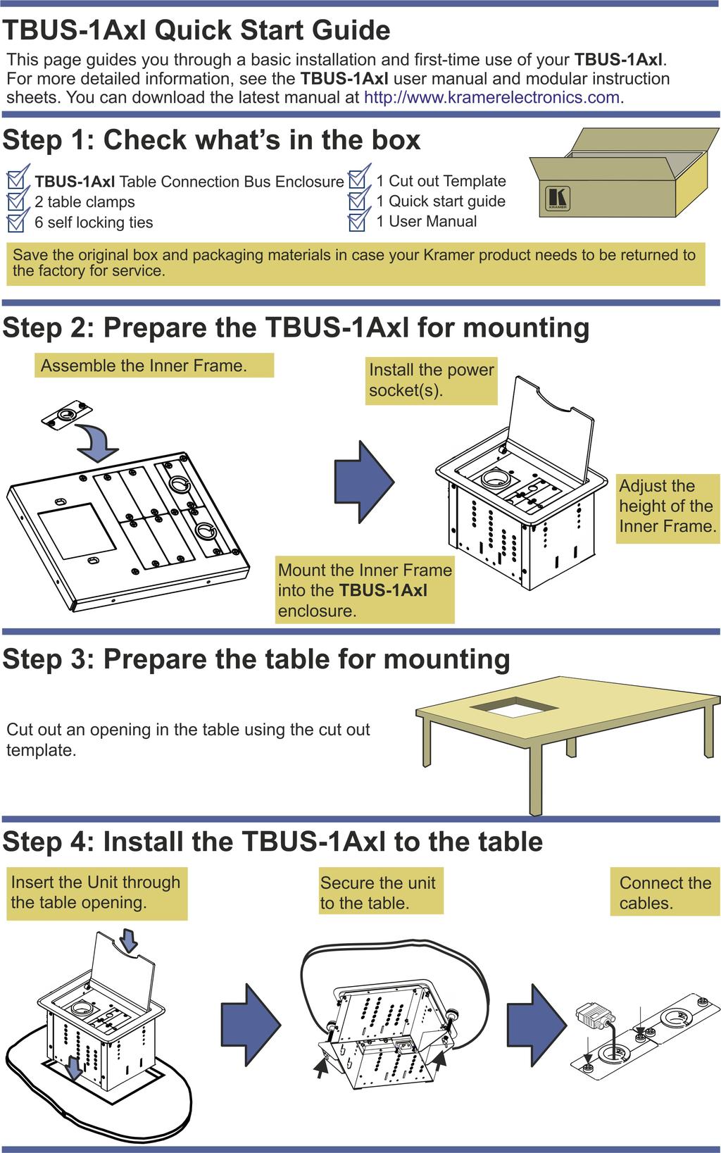
13 5 Installing the TBUS-1Axl To install the TBUS-1Axl perform the following steps: 1. Assemble the inner frame (see Section 5.1). 2. Install the inner frame (see Section 5.2). 3. Cut an opening in the table (see Section 5.3). 4. Insert the unit through the opening and secure to the table (see Section 5.4). 5. Connect the cables (see Section 5.5). 6. Insert the pass-through cables (see Section 5.6). 7. Adjust the height of the inner frame (see Section 5.7) 5.1 Assembling the Inner Frame The modules mounted on the inner frame can include single inserts and/or dual inserts as well as power sockets and various Kramer devices. This section describes how to assemble these modules. Each module kit comes with detailed assembly instructions. i Mounting the Inserts You can rearrange or remove any of the plates mounted on the inner frame and replace them with Kramer passive wall plates or connector modules for interfacing A/V type signals. To mount a Kramer insert or connector module: 1. Unscrew the two screws that fasten the blank plate to the inner frame and remove the blank plate. 2. Place the required Kramer insert over the opening, insert the two screws to fix the Kramer insert in place, and tighten them. 10 TBUS-1Axl - Installing the TBUS-1Axl
14 Figure 3: TBUS-1Axl Inner Frame (P/N: ) # Feature Function 1 Split Grommets Push apart slightly to insert cables 2 Split Brackets Support the split grommet for the pass through-cables 3 Blank Plates Four blank covers that can be replaced with wall plates as required 4 Power Socket Opening Suitable for a single power socket or the T-2INSERT 5 Adjustable Height Screw Holes For adjusting the height of the inner frame Mounting the Power Socket Assemblies To mount the power socket, place the power socket under the frame in its appropriate place and tighten with the two screws (supplied). Power socket kits come with assembly instructions. i Mounting a Kramer TOOL To mount a TOOL (for example, to the T1AF-14T), as shown in Figure 4: 1. Screw the spacers to their designated places (one on each side). 2. Insert the TOOL, from beneath, through the TOOL opening. TBUS-1Axl - Installing the TBUS-1Axl 11
15 3. Screw the screws (one on each side) through the frame holes and spacers. Figure 4: Installing a Kramer TOOL Installing the TOOL Blank To install the T-TBLANK, as shown in Figure 5: 1. Insert the T-TBLANK from beneath, through the TOOL opening. 2. Screw the screws (one on each side) through the frame. Figure 5: Installing the T-TBLANK TOOL Blank 12 TBUS-1Axl - Installing the TBUS-1Axl
.")
16 5.1.5 Mounting the Special Panel for RC-8IR The Kramer T-RC8IR for the TBUS-1Axl Table Connection bus is used to fit the Kramer RC-8IR Control Panel into the appropriate frame (P/N or P/N instead of two power sockets). Inner Frame Attachment hole Faceplate Attachment hole IR IN Opening Faceplate Attachment hole Inner Frame Attachment hole Figure 6: T-RC8IR (P/N: ) Remove the RC-8IR Faceplate 1. Before installing the T-RC8IR, unscrew the two faceplate attachment screws and remove the RC-8IR faceplate. Faceplate Attachment holes Faceplate Attachment holes Figure 7: RC-8IR Faceplate holestable Connection Bus TBUS-1Axl - Installing the TBUS-1Axl 13
17 2. Place the T-RC8IR over the RC-8IR enclosure so that both face plate holes are aligned with the face plate holes on the RC-8IR enclosure and the IR IN receiver fits into the IR IN opening. 3. Insert the faceplate screws through the T-RC8IR and RC-8IR enclosure Installation Instructions faceplate holes, and tighten. To install the T-RC8IR: 1. Insert the T-RC8IR assembly through the dual power socket opening from beneath. 2. Use the two power socket screws to tighten the T-RC8IR assembly in place Installing the SI-1VGA / RC-3TB To install the SI-1VGA / RC-3TB module, place it under the designated opening in the T1AF-14L (P/N: ) and then screw and tighten it in place using two screws supplied with the inner frame. 5.2 Installing the Inner Frame To install the inner frame: 1. Place the inner frame inside the TBUS-1Axl enclosure. 2. Set the required height using your fingers to bring the inner frame to the desired position, screw and tighten it in place using the height adjustment screws (supplied with the inner frame). i Inner frame kits come with assembly instructions. 14 TBUS-1Axl - Installing the TBUS-1Axl
18 5.3 Cutting an Opening in the Table To cut an opening in the table: 1. Place the included cut out template (that is included with your TBUS-1Axl) on the surface of the table exactly where you want to install the TBUS-1Axl. 2. Attach the template to the table with the included screws (if using the cut out template). 3. Following the inside edge of the template, cut a hole in the table surface with a sabre or keyhole saw according to the dimensions shown in Figure 8 (not to scale). i The thickness of the table should be 76.2 mm / 3 inches or less. Figure 8: Cut out Dimensions 4. Unscrew and remove the template from the surface of the table and clean the table surface. Take care not to damage the table. If needed, you can download a full-scale template from our Web site.! Kramer Electronics is not responsible for any damage caused to the table. TBUS-1Axl - Installing the TBUS-1Axl 15
19 5.4 Inserting the TBUS-1Axl through the Cut Out Opening To install TBUS-1Axl in the opening: 1. Remove the protective rubber guard from around the outer rim of the TBUS-1Axl housing. Beware of the sharp edge! 2. Carefully insert the unit into the prepared opening (see Figure 9). 3. Take the support brackets under the table and place them into the support bracket grooves on both sides of the unit (see Figure 2, item 7). 4. Verify proper alignment of the unit before tightening the mounting screws. 5. Tighten both mounting butterfly screws upward until they reach the table surface (from underneath). Tighten firmly (see Figure 9). 6. Tighten the locking butterfly screws downward until tight against the mounting bracket. Figure 9: Inserting TBUS-1Axl into the Prepared Opening 5.5 Connecting the Cables When replacing blank inserts with connector inserts (for example, VGA, audio, HDMI and so on): 1. Insert the cables to their appropriate connectors from underneath. 16 TBUS-1Axl - Installing the TBUS-1Axl
20 2. Secure the cables to the tie holes on the TBUS-1Axl. Do not secure the cables too tightly or too loosely. Leave a small amount of slack. 5.6 Inserting the Pass-through Cables To insert the pass through cables (for example, to connect a laptop) do the following: 1. Remove the two screws attaching the split pass-through bracket. 2. Remove the split grommet. 3. Insert the cable through the rectangular opening. 4. Open the split grommet slightly and insert the required cables. 5. Place the split bracket around the grommet and position this assembly over the inner frame. 6. Place the two screws appropriately and tighten the split bracket together with the grommet and inserted cables to the inner frame. 7. Insert the self-locking ties through the tie holes to secure the cables to the inside walls of the enclosure. Figure 10: Cable Pass-through Insert (P/N: ) TBUS-1Axl - Installing the TBUS-1Axl 17
21 5.7 Adjusting the Height of the Inner Frame If needed, you can adjust the inner frame height to accommodate large or bulky cables. To adjust, perform the following: 1. Remove the height adjustment screws, while supporting the surface from underneath with your fingers. 2. Raise or lower the inner frame to the required height, insert the screws, and tighten them in place. 18 TBUS-1Axl - Installing the TBUS-1Axl

22 6 Using the TBUS-1Axl Once the TBUS-1Axl is installed, you can easily customize it to suit your own requirements by plugging in the required A/V equipment, as illustrated in the example in Figure 11. Figure 11: TBUS-1Axl Boardroom Installation TBUS-1Axl - Using the TBUS-1Axl 19
23 7 Technical Specifications of the Assembled TBUS-1Axl POWER SOURCE (AC power limits): Single Socket Assemblies: Universal Maximum 5A per power outlet Fully compatible with power plugs in the UK, India, Italy and Denmark, as well as with the 2-prong Europlug. Partially compatible (if the polarity is reversed) with plugs in China, Switzerland, Israel and the USA. The universal socket does not supply grounding to plugs in Central Europe and France (you should order country specific sockets instead). Not compatible with South African plugs. USA Maximum 5A per power outlet Germany and EU Maximum 5A per power outlet Belgium and France Maximum 5A per power outlet Italy Maximum 5A per power outlet Australia Maximum 5A per power outlet Israel 220V AC, 50/60Hz, 5A Maximum 5A per power outlet South Africa 220V AC, 50/60Hz, 5A Maximum 5A per power outlet Dual Power Kit Assemblies: Universal USA Germany and EU France Israel 220V AC, 50/60Hz, 5A South Africa 220V AC, 50/60Hz, 5A FUSE RATING: T 6.3A 250V OPERATING TEMPERATURE RANGE: +5 to +45 Deg. Centigrade OPERATING HUMIDITY RANGE: 10 to 90% RHL, non-condensing STORAGE TEMPERATURE RANGE: -20 to +70Deg. C. STORAGE HUMIDITY RANGE: 5 to 95% RHL, non-condensing DIMENSIONS: 22.1cm x 18.2cm x 13cm (8.17" x 5.88" x 5.13") W, D, H WEIGHT: TBUS-1A: 1.5kg (3.3lbs) approx.; Table clamps: 0.26kg (0.57lbs); Metal template: 0.125kg (0.28lbs) ACCESSORIES: Power cord, six self-locking ties, metal template OPTIONS: Inner frames, passive wall plates and interfaces, power socket kits, power cord Specifications are subject to change without notice at 20 TBUS-1Axl - Technical Specifications of the Assembled TBUS-1Axl

24 TBUS-1Axl 21
25

26 For the latest information on our products and a list of Kramer distributors, visit our Web site where updates to this user manual may be found. We welcome your questions, comments, and feedback. Web site: info@kramerel.com! SAFETY WARNING Disconnect the unit from the power supply before opening and servicing
KRAMER ELECTRONICS LTD. USER MANUAL MODEL: TBUS-4xl Table Connection Bus. P/N: Rev 2
 KRAMER ELECTRONICS LTD. USER MANUAL MODEL: TBUS-4xl Table Connection Bus P/N: 2900-300067 Rev 2 Contents 1 Introduction 1 2 Getting Started 2 2.1 Achieving the Best Performance 2 2.2 Glossary 2 3 Overview
USER MANUAL. MODULAR TBUS-6xl Table Connection Bus MODEL: P/N: Rev 3
 KRAMER ELECTRONICS LTD. USER MANUAL MODEL: MODULAR TBUS-6xl Table Connection Bus P/N: 2900-300073 Rev 3 Contents 1 Introduction 1 2 Getting Started 2 2.1 Achieving the Best Performance 2 2.2 Glossary
USER MANUAL MODEL: TBUS-1N Table Connection Bus
 USER MANUAL MODEL: TBUS-1N Table Connection Bus P/N: 2900-300656 Rev 3 www.kramerav.com Contents 1 Introduction 1 2 Getting Started 2 2.1 Achieving the Best Performance 2 2.2 Recycling Kramer Products
USER MANUAL. MODULAR TBUS-10xl Table Connection Bus MODEL: P/N: Rev 4
 KRAMER ELECTRONICS LTD. USER MANUAL MODEL: MODULAR TBUS-10xl Table Connection Bus P/N: 2900-300688 Rev 4 Contents 1 Introduction 1 2 Getting Started 2 2.1 Achieving the Best Performance 2 2.2 Glossary
USER MANUAL. 482xl Bidirectional Audio Transcoder MODEL: P/N: Rev 3
 KRAMER ELECTRONICS LTD. USER MANUAL MODEL: 482xl Bidirectional Audio Transcoder P/N: 2900-000134 Rev 3 Contents 1 Introduction 1 2 Getting Started 2 2.1 Achieving the Best Performance 2 2.2 Safety Instructions
USER MANUAL. 103EQ 3 Band Parametric EQ MODEL: P/N: Rev 1.
 USER MANUAL MODEL: 103EQ 3 Band Parametric EQ P/N: 2900-300594 Rev 1 www.kramerav.com Contents 1 Introduction 1 2 Getting Started 2 2.1 Achieving the Best Performance 2 2.2 Safety Instructions 2 2.3
KRAMER ELECTRONICS LTD. USER MANUAL MODEL: 912 Power Amplifier. P/N: Rev 2
 KRAMER ELECTRONICS LTD. USER MANUAL MODEL: 912 Power Amplifier P/N: 2900-000684 Rev 2 Contents 1 Introduction 1 2 Getting Started 2 2.1 Achieving the Best Performance 2 3 Overview 3 3.1 Defining the 912
KRAMER ELECTRONICS LTD. USER MANUAL MODELS: SPK-C612 Closed-back Ceiling Speakers SPK-C412 SPK-C411. P/N: Rev 1
 KRAMER ELECTRONICS LTD. USER MANUAL MODELS: SPK-C612 Closed-back Ceiling Speakers SPK-C412 Closed-back Ceiling Speakers SPK-C411 Closed-back Ceiling Speakers P/N: 2900-300113 Rev 1 Contents 1 Introduction
model tsa-sa48 Sliding Crosscut Table installation guide
 model tsa-sa48 Sliding Crosscut Table installation guide A Note About Color Variations Among Anodized Aluminum Components Congratulations on the purchase of this SawStop Sliding Crosscut Table. We at SawStop
EPPA2-KIT DUAL MONITOR ARM CONVERSION
 EPPA2-KIT DUAL MONITOR ARM CONVERSION EPPA2-KIT Rev A 10/17 Model EPPA2-KIT-XXX ASSEMBLY AND ADJUSTMENT EPPA2-KIT PARTS AND TOOLS PLEASE REVIEW these instructions before beginning the assembly and adjustment
Sliding Crosscut Table installation guide
 Sliding Crosscut Table installation guide model tsa-sa48 A Note About Color Variations Among Anodized Aluminum Components Congratulations on the purchase of this SawStop Sliding Crosscut Table. We at SawStop
INSTALLATION INSTRUCTIONS LARGE FLAT PANEL IN WALL ENCLOSURE Model: PAC-500
 INSTALLATION INSTRUCTIONS LARGE FLAT PANEL IN WALL ENCLOSURE Model: PAC-500 Specifications: Designed for in-wall installation spanning a minimum of 3 wood studs, 16" on center. Accomodates MWR, PWR and
Shepherd 210A Fingerprint Door Lock Installation Manual V1.1
 Shepherd 210A Fingerprint Door Lock Installation Manual V1.1 Hongda USA Inc. 2505 Technology Dr. #2-6A, Hayward, CA 94545, USA Phone: (510) 887-5682 Fax: (510) 372-0487 Email: info@hongdausa.com Website:
Rain Gauge Smart Sensor (Part # S-RGA-M002, S-RGB-M002)
") (Part # S-RGA-M002, S-RGB-M002) The Rain Gauge smart sensor is designed to work with HOBO Station loggers. The smart sensor has a plug-in modular connector that allows it to be added easily to a HOBO Station.
(Part # S-RGA-M002, S-RGB-M002) The Rain Gauge smart sensor is designed to work with HOBO Station loggers. The smart sensor has a plug-in modular connector that allows it to be added easily to a HOBO Station.
FOLDING MACHINE PF-45A OPERATOR MANUAL 1. FUNCTION
 FOLDING MACHINE OPERATOR MANUAL 1. FUNCTION The folding machine is used to fold documents stand alone or in combination with a system 7. Sheets can be folded in various types. These are: single fold; letter
WELCOME TO ZUMA R300 ULTRA-LOW NOISE WORLD TOUR READY
 WELCOME TO ZUMA R300 ULTRA-LOW NOISE WORLD TOUR READY Strymon power supplies are the highest horsepower, most technologically advanced effects pedal power supplies of their kind. Zuma R300 delivers clean,
Installation and Assembly - Universal Articulating Swivel Double-Arm for 42" - 60" Plasma Screens
 Installation and Assembly - Universal Articulating Swivel Double-Arm for 42" - 60" Plasma Screens Models: PLAV 70-UNL, PLAV 70-UNL-S PLAV 70-UNLP, PLAV 70-UNLP-S R This product is UL Listed. It must be
INSTALLATION INSTRUCTIONS
 INSTALLATION INSTRUCTIONS Trans4mer Grille Guard/Winch Mount Kit 645 For Chevrolet Silverado 500HD & 3500 This WARN Trans4mer system can be customized to give your Chevy Silverado a wide variety of looks,
Your order will be shipped with the supports and rail components packaged inside the ramp package. Each accessory package is labeled.
 instructions About Your Order. Your order will be shipped with the supports and rail components packaged inside the ramp package. Each accessory package is labeled. Check the Order Before the Carrier leaves!
DEC 3000 Models 500/500S/800/800S/900/900S AXP Rackmount Installation Guide
 DEC 3000 Models 500/500S/800/800S/900/900S AXP Rackmount Installation Guide Order Number: EK-R355S-IN. C01 Revision/Update Information: This a revised document. September 1994 This guide is a support and
Installation and Service Manual
 LCD Attachment Installation and Service Manual 2 Table of Contents Parts List...2 Hardware Kits...3 Bike, Cross Trainer and Stepper Start...4 Steps in Assembling the Bracket...5 Installation Instructions
S6 User s Manual USER S MANUAL ver. 1.0
 S6 User s Manual SKEETER - 1U LOW PROFILE SOLUTION Table of Contents Tabletop Configuration 2 Tabletop Configuration Accessories 4 Slide Configuration 5 slide configuration accessories 7 rack Mount configuration
Installation instructions, accessories. TV receiver, digital
 Installation instructions, accessories Instruction No 30756561 Version 1.1 5 Part. No. 30756181, 30756569 TV receiver, digital Volvo Car Corporation TV receiver, digital- 30756561 - V1.1 Page 1 / 36 Equipment
Portofino Case2 Installation Guide
 Portofino Case2 Installation Guide vjun16 (for 17 or 24 mm Surface Wall Profile) DO NOT ASSEMBLE WITHOUT FULLY READING THESE INSTRUCTIONS Page 2 Thank you for purchasing this Portofino Case 2 shower enclosure.
Pleated Shades with Corded Top Down / Bottom Up Option
 Pleated Shades with Corded Top Down / Bottom Up Option Installation Instructions Email: customerservice@blindster.com Call us: (888) 256-8672 Mon - Fri 8am - 7pm (CT) Congratulations on purchasing Pleated
Flat Panel Stand FPZ-655. for 32" to 55" Flat Panel Screens FEATURES. Reinforced universal adapter plate for a strong hold
 FPZ-655 Flat Panel Stand for 32" to 55" Flat Panel Screens For a viewing experience that really stands out, Peerless FPZ-655 Universal Flat Panel Stand for 32" 55" flat panel TVs provides a brilliant combination
Portofino Installation Guide
 vjul16 (for 17 or 24 mm Surface Wall Profiles) DO NOT ASSEMBLE WITHOUT FULLY READING THESE INSTRUCTIONS Page 2 Thank you for purchasing this Portofino shower enclosure. Please study these instructions
Assembly Instructions
 InTandem Table System November 20 InTandem Table System - Worksurface #4 x/" 4 wood screw power beam Tools Provided T-0 Extended Torx Driver T-25 Torx Driver Additional Tools Required Soft protective
INSTALLATION INSTRUCTIONS Small Flat Panel Mounts Model: F-Series
 INSTALLATION INSTRUCTIONS Small Flat Panel Mounts Model: F-Series This Instruction Manual covers most of the F-Series wall and desk mounts, as well as selected F-Series pole mounts. NOTE: Some F-Series
Aluminum Frame Type Instruction Manual
 Aluminum Frame TypeInstruction Manual Thank you for selecting our product. Before starting installation, please read this manual thoroughly to ensure correct installation. Please keep this manual at hand
Deauville Installation Guide
 vjul16 (for 17 or 24 mm Surface Wall Profiles) DO NOT ASSEMBLE WITHOUT FULLY READING THESE INSTRUCTIONS Page 2 Thank you for purchasing this Deauville shower enclosure. Please study these instructions
Installation and Assembly: Ceiling mount for LCD screens up to 29"
 Installation and Assembly: Ceiling mount for LC screens up to 29" Models: LCC 18, LCC 18-S, LCC 36, LCC 36-S Patent Pending Features: Comes in two adjustable height ranges (in 1" increments): 18"-30" and
SCION FR-S REAR SPOILER Preparation
 Preparation Part Number: PT938-18130-XX Kit Contents Item # Quantity Reqd. Description 1 1 Spoiler 2 2 Strut 3 1 Hardware Bag Hardware Bag Contents Item # Quantity Reqd. Description 1 2 M6 x 1 Nut with
OPERATIONS MANUAL. Port-O-Slitter
 Tapco Products Company The World Leader in Specialty Tools for the Professional Port-O-Slitter OPERATIONS MANUAL General instructions, set up, accessories and guide to using your portable precision slitting,
19 to 39 TV WALL MOUNT - FULL MOTION
 19 to 39 TV WALL MOUNT - FULL MOTION RF-HTVMMAB For wood-stud and concrete wall installations Safety information and specifications...2 Tools needed...2 Package contents...3 Installation instructions...5
FS-527 Finisher INSTALLATION MANUAL
 FS-527 Finisher INSTALLATION MANUAL Index FS-527 (d-color MF360/MF280/MF220) I. Accessory parts... II. Confirmation before installation... 2 III. Installation procedures... 3 FS-527 (d-color MF45) I. Accessory
Installation and Assembly - Universal Articulating Swivel Double-Arm for 42" - 60" Plasma Screens
 Installation and Assembly - Universal Articulating Swivel Double-Arm for 42" - 60" Plasma Screens Models: PLAV 70-UNL, PLAV 70-UNL-S PLAV 70-UNLP, PLAV 70-UNLP-S R This product is UL Listed. It must be
The Bowflex Revolution XP Home Gym Assembly Instructions. P/N: Rev ( /0 )
") P/N: 001-7057 Rev ( /0 ) The Bowflex Revolution XP Home Gym Assembly Instructions 2 Table of Contents Before You Start... 2 Tools You Will Need / Hardware Contents... 3 Box Contents... 6 Assembling Your
P/N: 001-7057 Rev ( /0 ) The Bowflex Revolution XP Home Gym Assembly Instructions 2 Table of Contents Before You Start... 2 Tools You Will Need / Hardware Contents... 3 Box Contents... 6 Assembling Your
MKPLAY VAULT MINI TRAMPOLINE SERIES
 MKPLAY VAULT MINI TRAMPOLINE SERIES 55 INCH (4.5FT) TRAMPOLINE WITH SAFETY NET ENCLOSURE Weight Limit 100lbs (45kg) Person Limit 1 Persons Age Limit 3-6 years 1 TABLE OF CONTENTS Parts List Trampoline
Pickup Box Utility Rack Package Installation (Instruction ID: )
") 017 Chevrolet Colorado Pickup - WD (VIN S) Canyon, Colorado Accessory Installation Manual N America Document ID: 3966961 Pickup Box Utility Rack Package Installation (Instruction ID:3144879) Installation
017 Chevrolet Colorado Pickup - WD (VIN S) Canyon, Colorado Accessory Installation Manual N America Document ID: 3966961 Pickup Box Utility Rack Package Installation (Instruction ID:3144879) Installation
Installing flat panels on the MPL15 wall mount
 Installing flat panels on the MPL15 wall mount The MPL15 (DS-VW775) is a full-service video wall mount that can accommodate tiled LCD panels with up to a 400 x 400 mm VESA pattern in portrait and landscape
INSTALLATION INSTRUCTIONS Small Flat Panel Height-Adjustable, Extended Pitch Swing Arm Wall Mount Model KWE-110
 INSTALLATION INSTRUCTIONS Small Flat Panel Height-Adjustable, Extended Pitch Swing Arm Wall Mount Model KWE-110 The KWE dual swing arm wall mount is designed to provide a broad range of viewing for Small
Installation and Assembly: In-wall Mount for 32" to 71" Flat Panel Screens
 Installation and Assembly: In-wall Mount for 32" to 71" Flat Panel Screens Model# IM760P, IM760P-S IM760PU, IM760PU-S Screen size range 32" to 71" (81 to 180 cm) 32" to 60" (81 to 152 cm) IM760P IM760P-S
INSTALLATION INSTRUCTIONS HEAVY DUTY TILT WALL MOUNT Model: PPH-2000
 INSTALLATION INSTRUCTIONS HEAVY DUTY TILT WALL MOUNT Model: PPH-2000 Specifications: Accomodates Akira and Orion 84" displays without interface bracket; accomodates other large flat panel displays with
Fiber Splice Box (FSB-D) Installation Instructions
 Installation Instructions") Fiber Splice Box (FSB-D) Installation Instructions Table of Contents General Product Information... 1.0 Safety Precautions... 2.0 Tools Required... 3.0 Package Contents... 4.0 Installing the Product Unpacking...
Fiber Splice Box (FSB-D) Installation Instructions Table of Contents General Product Information... 1.0 Safety Precautions... 2.0 Tools Required... 3.0 Package Contents... 4.0 Installing the Product Unpacking...
Wall mounting bracket
 Install Manual Wall mounting bracket Please read this manual carefully before operating your set and retain it for future reference. OSW200 P/NO : MFL63640578 (1502-REV01) www.lg.com COMPONENT Install
Installation Manual for the Rockmeister Roof Ladder
 Installation Manual for the Rockmeister Roof Ladder Exclusively for Mercedes-Benz Geländewagen W460, W461 & W463 with single rear door NOTE: W460 & W461 models have a different Frame Bracket than the W463.
Customer Notice: Congratulations again on your SawStop purchase, and thank you! -SawStop Tualatin, OR
 Customer Notice: Congratulations on the purchase of this Sliding Crosscut Attachment. As the owner of a SawStop saw, you are familiar with our high standards for quality, fit and finish. Different from
Installation Instructions
 For Medium (15-18.5K) + Heavy duty (22-28.5K) Air Conditioner READ BEFORE INSTALLING UNIT To avoid risk of personal injury, property damage, or product damage due to the weight of this device and sharp
BrewsBySmith.com STC DIY Kit
 BrewsBySmith.com STC-1000 + DIY Kit Contact Information: Greg Smith www.brewsbysmith.com greg@boostbysmith.com I. Hardware Included: STC-1000 flashed with latest software (v1.06 currently) (if purchased)
Standard Pole Mount Parabolic Antenna Mounting Instructions 3 ft. (90cm) & 4 ft. (120cm)
 & 4 ft. (120cm)") 495 R Billerica Ave. N. Billerica, MA 01862 USA Tel: (978) 459-8800 Fax: (978) 459-3310 / 8814 www.radiowavesinc.com email: sales@radiowavesinc.com Standard Pole Mount Parabolic Antenna Mounting Instructions
495 R Billerica Ave. N. Billerica, MA 01862 USA Tel: (978) 459-8800 Fax: (978) 459-3310 / 8814 www.radiowavesinc.com email: sales@radiowavesinc.com Standard Pole Mount Parabolic Antenna Mounting Instructions
Z-DECK MANUAL. Z-Deck. Stable platform for electrophysiology and neuroscience Manual Version 2.1. Worldwide distribution
 Z-Deck Stable platform for electrophysiology and neuroscience Manual Version 2.1 Worldwide distribution Prior Scientific, Ltd Prior Scientific, Inc Prior Scientific, GmbH Prior Scientific KK Cambridge,
ELPMB27. Short Throw Projector Wall Mount Installation Manual xxx(fr) xxx(de) xxx(it) xxx(es) xxx(pt) xxx(zhs)
 xxx(de) xxx(it) xxx(es) xxx(pt) xxx(zhs)") ELPMB27 Short Throw Projector Wall Mount Installation Manual xxx(fr) xxx(de) xxx(it) xxx(es) xxx(pt) xxx(zhs) Safety Instructions Before using the wall mount, make sure you read all of the safety instructions
ELPMB27 Short Throw Projector Wall Mount Installation Manual xxx(fr) xxx(de) xxx(it) xxx(es) xxx(pt) xxx(zhs) Safety Instructions Before using the wall mount, make sure you read all of the safety instructions
LIGHT FIXTURES MUST BE COMPLETELY INSTALLED PRIOR TO CEILING CONSTRUCTION
 CAUTION: BEFORE BEGINNING INSTALLATION REVIEW LAYOUT DRAWINGS, AND SHIPMENT. MAKE SURE ALL LIGHT S AND MATERIALS ARE ON SITE AND READILY ACCESSIBLE. IF ANY ICON MATERIALS ARE MISSING, CONTACT ICON INTERNATIONAL
LAN Locker Adjustable Shelves
 Adjustable Shelves LAN LOCKER ADJUSTABLE SHELVES * Adjustable Shelves are available for LAN LOCKER widths: 24, 30, 48, 60, and 72. * When installing more than one Adjustable Shelf, it is recommended that
LCD MONITOR/TV WALL MOUNT
 INSTALLATION INSTRUCTIONS LCD MONITOR/TV WALL MOUNT DUAL DESK CLAMP (RFCD-110) S CAUTION CAUTION A alerts you to the possibility of serious injury or death if you do not follow the instructions. A CAUTION
S E L E C T I O N. Arm Curl. User manual
 S E L E C T I O N T H E S T R E N G T H E V O L U T I O N User manual The identification plate of the and manufacturer, affixed behind the seat, gives the following details: A Name and address of the manufacturer
OnSite 19 /15U Wall Rack Model WR-15U
 WR-15U Aug 2017 001-01-000091 Rev.000 OnSite 19 /15U Wall Rack Model WR-15U 1. OVERVIEW... 1 2. APPLICATIONS... 1 3. DESCRIPTION... 2 4. INSTALLATION... 2 5. TESTING AND TROUBLESHOOTING... 5 6. CUSTOMER
M2 Antenna Systems, Inc. Model No: 2M7
 M2 Antenna Systems, Inc. Model No: 2M7 SPECIFICATIONS: Model... 2M7 Frequency Range... 144 To 148 MHz *Gain... 12.3 dbi Front to back... 20 db Typical Beamwidth... E=43 H=50 Feed type... T Match Feed Impedance....
MM540 Installation Instructions IMPORTANT SAFETY INSTRUCTIONS - SAVE THESE INSTRUCTIONS
 MM50 Installation Instructions IMPORTANT SAFETY INSTRUCTIONS - SAVE THESE INSTRUCTIONS Please read this entire manual before you begin. Do not unpack any contents until you verify all requirements on PAGE.
INSTALLATION INSTRUCTIONS POLE/PITCH- ADJUSTABLE MOUNT Model: TPM-2000 SERIES
 INSTALLATION INSTRUCTIONS POLE/PITCH- ADJUSTABLE MOUNT Model: TPM-2000 SERIES Specifications: Weight capacity of 150 lbs. (68 kg). Provides tilt range from 5 up to 15 down. Accommodates vertical pole (1"
INSTALLATION INSTRUCTIONS
 INSTALLATION INSTRUCTIONS Trans4mer Grille Guard/Winch Mount Kit 60036 (Black) & 60037 (Chrome) For Chevrolet Silverado 3/4 Ton Trucks (Not suitable for Winches larger than,000 lbs.) As you read these
ABM International, Inc.
 ABM International, Inc. Lightning Stitch required 1 1.0: Parts List head and motor assembly (Qty. 1) Reel stand (Qty. 1) Needle bar frame clamp (Qty. 1) Motor drive (Qty. 1) 2 Cable harness with bracket
Luxe Linen Honeycomb Shades
 Step by Step Installation Instructions Luxe Linen Honeycomb Shades Customer Service 800.248.8888 or visit us online at smithandnoble.com Table of Contents Getting Started...3 THANK YOU for purchasing from
S E L E C T I O N. Upper Back. User manual
 and S E L E C T I O N T H E S T R E N G T H E V O L U T I O N User manual and and The identification plate of the and manufacturer, affixed to the frame on the side opposite the padded rest, gives the
Deck Mount Installation with Bench
 Deck Mount Installation with Bench 1. Mark track with square. 2. Cut tracks with saw. 3. Drill ¼ hole (if needed.) 4. Countersink track. 5. Countersink all track 6. File all track ends. ends. 7. Lay out
Fixed Wall Arm. Installation Guide. Part number Rev E 2012 PolyVision Corporation All rights reserved
 Fixed Wall Arm Installation Guide Part number 2002003-001 Rev E 2012 PolyVision Corporation All rights reserved Table of contents Important Safety Instructions... 3 Overview... 4 Important considerations...
PROFILE Flat Panel Console System Installation Manual
 PROFILE Flat Panel Console System Installation Manual Table of Contents Page Introduction... 2 Important Safety Information...3, 4 Installation Overview... 4, 5, 6 Single Sided/Single Unit... 7 Double
INSTALLATION MANUAL H A
 INSTALLATION MANUAL CABINET RACK CR-43-6 (4-UNIT SIZE) Be sure to read this installation manual thoroughly before installing this Cabinet Rack. For the mounting procedures of the components and the relevant
Important Safety Information
 OWNER'S MANUAL Important Safety Information 1. Read these instructions. 2. Keep these instructions. 3. Heed all warnings. 4. Follow all instructions. 5. Do not use this apparatus near water. 6. Clean only
UNDERPINNERS CS 88 & CS 89 FOOT-OPERATED PNEUMATIC. Technical and User Manual. Version 1 au 12 / 01. Cassese / Communication
 UNDERPINNERS CS 88 & CS 89 FOOT-OPERATED PNEUMATIC Technical and User Manual Version 1 au 12 / 01 Cassese / Communication CS88 / CS 89 - Technical and User Manual CONTENTS PAGE N INTRODUCTION ACCESSORIES
TECHNICAL INFORMATION
 TECHNICAL INFORMATION P 1 / 11 Model No. Description CONCEPT AND MAIN APPLICATIONS Specification Standard equipment TCT saw blade... 1 Rear table set (exclusively Europe, Turkey, South Africa..1 2704 This
OnSite 19 /15U Wall Rack Model WR-15U
 WR-15U November 2018 001-01-000091 Rev.001 OnSite 19 /15U Wall Rack Model WR-15U 1. OVERVIEW... 1 2. APPLICATIONS... 1 3. DESCRIPTION... 2 4. INSTALLATION... 2 5. TESTING AND TROUBLESHOOTING... 5 6. CUSTOMER
MantelMount. TM1A Installation Instructions IMPORTANT SAFETY INSTRUCTIONS - SAVE THESE INSTRUCTIONS
 MantelMount TMA Installation Instructions IMPORTANT SAFETY INSTRUCTIONS - SAVE THESE INSTRUCTIONS TM Thank you for choosing the MantelMount television wall mount. Please read this entire manual before
ES3640e MFP Technician s Installation Guide
 Technician s Installation Guide Configuration A with High Capacity Feeder HCF.jpg Configuration B with Second Tray and Cabinet cab.jpg With optional Finisher: ES3640e MFP 01_Finis her.jpg 1 Warning Icon.jpg
Installation Instructions Road King Classic Saddlebag Bezels
 Installation Instructions Road King Classic Saddlebag Bezels Thank you for your purchase of Bagger Audio Road King Classic Saddlebag Bezels for your Harley-Davidson motorcycle. We have carefully engineered
LSM-BE 7 - Lift System Medium with Box Enclosure
 SHEET 1 of 9 DESIGN HIGHLIGHTS Quiet smooth lifting action at approximately 40mm [1.6] per second Full cable management Wide range of mounting options 24V DC motor. Suitable for direct DC supply Marine
OPERATIONS MANUAL. Port-O-Slitter
 OPERATIONS MANUAL Port-O-Slitter General instructions, set up, accessories and guide to using your portable precision slitting, rib forming and perforating system Saves hours on large siding jobs! Featuring:
OPERATOR'S MANUAL ROUTER MOUNTING KIT
 OPERATOR'S MANUAL MOUNTING KIT 4950301 (FOR USE WITH BT3000 AND BT3100 TABLE SAWS) Your new router mounting kit has been engineered and manufactured to Ryobi's high standard for dependability, ease of
ARROW SAW PRECISE CUT 8000 RPM WITH DUST COLLECTING ATTACHMENT INSTRUCTION BOOK MODEL NO
 ATTENTION If any components of this unit are broken or the unit does not operate properly, please contact Cabela s Customer Service. Retail Store Purchases: 1-800-905-2731 (U.S. & Canada) Catalog and Internet
QLF214 INSTRUCTION MANUAL
 QLF214 INSTRUCTION MANUAL We ll Make It Stress-Free If you have any questions along the way, just give us a call. 1-800-359-5520 We re ready to help! Scan for easy install video san.us/1145 CAUTION: IMPORTANT
MODULAR BUMPER INSTALLATION MANUAL
 MODULAR BUMPER INSTALLATION MANUAL Parts List* 1 Center section 1 Side extension, passenger / right 1 Side extension, driver / left 1 Side cap, passenger / right 1 Side cap, driver / left 1 Brush guard,
MODEL 9301E. Extra Heavy Duty Full Extension Drawer Slide Up to 600-lb. [272 kg.] Load Rating Optional Accessory Platform Brackets*
![MODEL 9301E. Extra Heavy Duty Full Extension Drawer Slide Up to 600-lb. [272 kg.] Load Rating Optional Accessory Platform Brackets*](/thumbs/71/66171988.jpg "MODEL 9301E. Extra Heavy Duty Full Extension Drawer Slide Up to 600-lb. [272 kg.] Load Rating Optional Accessory Platform Brackets*") 1 MODEL 9301E APPLICATIONS: This versatile slide is designed for use in a variety of heavy-duty storage applications. Please preview the application information provided on the following pages for further
1 MODEL 9301E APPLICATIONS: This versatile slide is designed for use in a variety of heavy-duty storage applications. Please preview the application information provided on the following pages for further
User Instructions Multiline Otter Scoreboard Caddy Assembly
 List of parts: User Instructions Multiline Otter Scoreboard Caddy Assembly Single Caddy Double Caddy 1 1 Base assembly with attached wheels 2 4 1 1 2 4 4 8 10 20 12 Uprights (60 or 74 aluminum extrusion)
Mod-E Pro Electric L-Shaped Standing Desk
 The Height of Healthy Design Mod-E Pro Electric L-Shaped Standing Desk ASSEMBLY AND OPERATION MultiTable Mod-E Pro Electric L-Shaped Table Base PARTS AND TOOLS PLEASE REVIEW these instructions before beginning
TABLE OF CONTENTS REQUIRED TOOLS
 TABLE OF CONTENTS SECTION SECTION TITLE PAGE NO. 1 2 3 4 5 Assembling Mounting Structure Installing Bicycle Supports Mounting Rack to Wall Adding Sections Customizing Rack Configuration REQUIRED TOOLS
KINEX benching Installation Guide
 KINEX benching Installation Guide Index KINEX Installation Guide SINGLE RUN SINGLE RUN Assembly Components... Assembly Outline...5 DOUBLE RUN Assembly Components...8 Assembly Outline...9 Assembly Instructions
Hatchback Wing Riser Kit
 Hatchback Wing Riser Kit 2015-06-11 Thank you for purchasing this PERRIN product for your car! Installation of this product should only be performed by persons experienced with installation of aftermarket
200 Watt Passive Shunt Module
 Installation Instructions 200 Watt Passive Shunt Module (Catalog Number 9101-1183) Drives can require external power dissipation when large inertial loads are present. To ensure that faults due to excessive
Assembly Instructions
 Assembly Instructions VESA Flex Flip Lounge 1. Contents VESA Flex Flip Lounge p.3-18 p.19-37 p.38-48 p.49-58 2. Assembly Instructions VESA 3. What's in the Box Case Washer x1 T20 Driver Bit x1 M4 Split
NetShelter VS Enclosure. User s Manual
 NetShelter VS Enclosure User s Manual Contents Product Description...1 NetShelter VS enclosures.......................... 1 Product Features.................................... 2 Hardware, grommets, and
Product must be installed as shown using the screws and brackets provided. Use of incorrect hardware could result in damage to the product.
 General Notes These installation instructions are intended to be comprehensive for a typical Keyeira/Presto configuration. Your configuration may differ. If you have questions contact Geiger Customer Service
Thank you for purchasing out product! *Please read these instructions and follow them step by step. *
 Page 1 of 7 AD17 AA DS 4 X 16 T12 Thank you for purchasing out product! *Please read these instructions and follow them step by step. * STEP 1. Slide two support posts (REF. # 24) into the two outside
English User's Guide
 User's Guide Imacon Flextight 343 2 2003 Imacon A/S. All rights reserved. Imacon Flextight 343 User's Guide, Part No 70030009, revision B. The information in this manual is furnished for informational
INSTALLATION INSTRUCTIONS
 INSTALLATION INSTRUCTIONS Trans4mer Mounting System Dodge Ram Kit No. 65220, 73132, 75525, 76253 (black) or 65221, 73133, 75530, 76254 (stainless) As you read these instructions, you will see NOTES, CAUTIONS
LCD TV WALL MOUNT INSTALLATION INSTRUCTIONS. DUAL Swing Arm (RFWD-110) WARNING
 WARNING") INSTALLATION INSTRUCTIONS LCD TV WALL MOUNT DUAL Swing Arm (RFWD-110) WARNINGS WARNING WARNING CAUTION CAUTION The maximum weight to be installed on the RFWD wall mount is 40 lbs. (18.1 kg). The RFWD is
INSTALLATION INSTRUCTIONS LCD TV WALL MOUNT DUAL Swing Arm (RFWD-110) WARNINGS WARNING WARNING CAUTION CAUTION The maximum weight to be installed on the RFWD wall mount is 40 lbs. (18.1 kg). The RFWD is
CM340B STOP READ ALL OF THE FOLLOWING INSTRUCTIONS BEFORE REMOVING SERVER CABINET FROM SKID
 CM340B STOP READ ALL OF THE FOLLOWING INSTRUCTIONS BEFORE REMOVING SERVER CABINET FROM SKID NET-ACCESS Server Cabinets Panduit Corp. 2010 INSTRUCTIONS CM340B CS1 (1) Base Cabinet (2) Solid Side Panels
Subwoofer. - F required in S40 with low cargo compartment floor - G always required in V50 - H required in V50 with low cargo compartment floor
 1 of 26 Subwoofer 2 of 26 INTRODUCTION - NOTE! Read through the whole installation instruction before starting the work. - The front page gives the date of this edition and the edition it replaces - The
Curium 19H Installation Instructions & Parts List
 Curium 19H Installation Instructions & Parts List Illustration Curium 19H Right Hand Page 1 of 15 01/07/2016 Revision 2.1 IMPORTANT This shower screen / enclosure must be installed by suitably qualified
Linear Hook- on Worksurfaces
 Linear Hook- on Worksurfaces Linear Hook-On Worksurfaces come in three depths and seven lengths. Different worksurfaces have different reqirements for installation that are outlined below. 27 inch deep