USER MANUAL MODEL: TBUS-1N Table Connection Bus
|
|
|
- Alan Hardy
- 5 years ago
- Views:
Transcription
1 USER MANUAL MODEL: TBUS-1N Table Connection Bus P/N: Rev 3
2
3 Contents 1 Introduction 1 2 Getting Started Achieving the Best Performance Recycling Kramer Products 3 3 Overview 4 4 Defining the TBUS-1N TBUS-1N Optional Inner Frames TBUS-1N Accessories Power Socket Options Power Cord Options 11 5 Installing the TBUS-1N Assembling the Inner Frame Installing the Inner Frame Cutting an Opening in the Table Inserting the TBUS-1N through the Cut Out Opening Connecting the Cables Inserting the Pass-through Cables Adjusting the Height of the Inner Frame 20 6 Using the TBUS-1N 21 7 Technical Specifications of the TBUS-1N 22 Figures Figure 1: TBUS-1N inside Table 4 Figure 2: TBUS-1N Table Connection Bus Front View 5 Figure 3: TBUS-1N Inner Frame (P/N: ) 13 Figure 4: Installing a Kramer TOOL 14 Figure 5: Installing the T-TBLANK TOOL Blank 15 Figure 6: T-RC8IR (P/N: ) 15 Figure 7: RC-8IR Faceplate Holes Table Connection Bus 16 Figure 8: Cut Out Dimensions 18 Figure 9: Inserting TBUS-1N into the Prepared Opening 19 Figure 10: Cable Pass-through Insert (P/N: ) 20 Figure 11: TBUS-1N Boardroom Installation 21 TBUS-1N Contents i
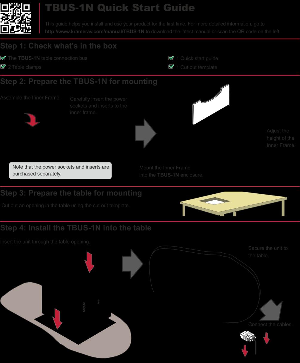
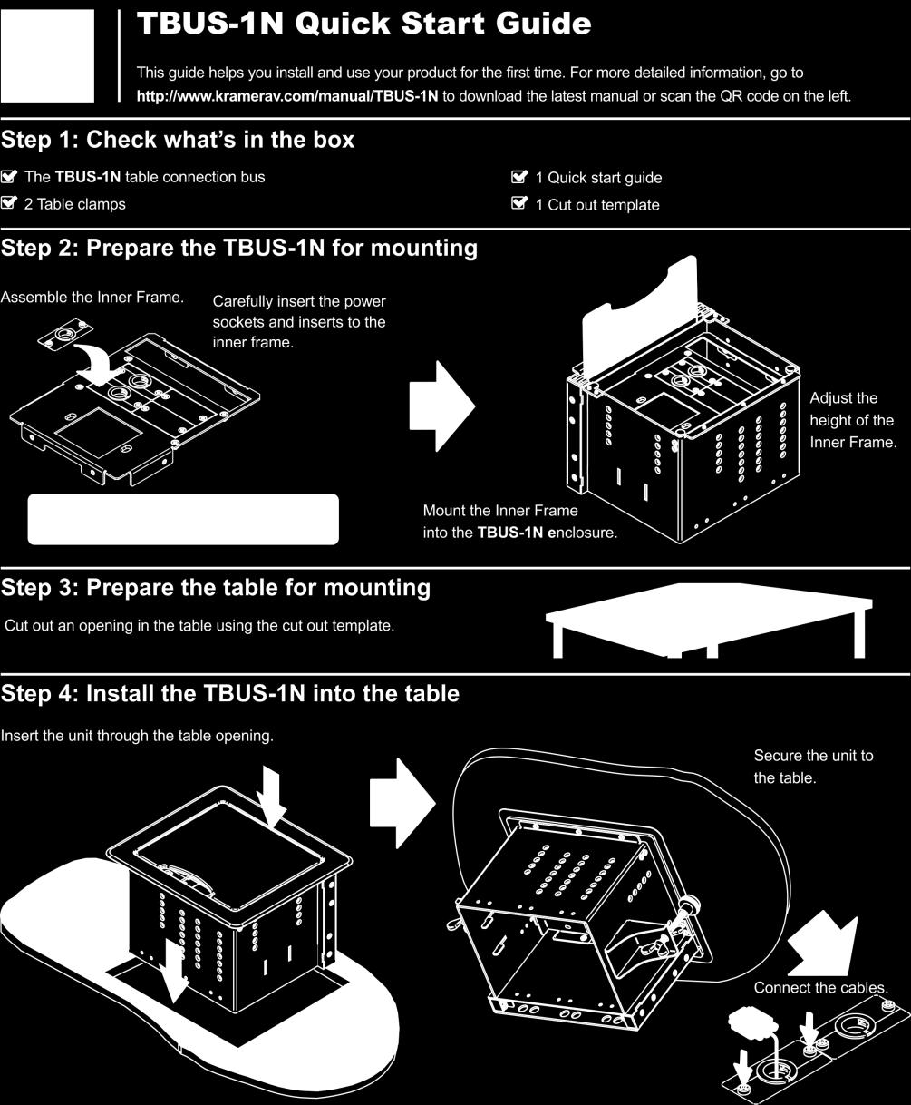
4 1 Introduction Welcome to Kramer Electronics! Since 1981, Kramer Electronics has been providing a world of unique, creative, and affordable solutions to the vast range of problems that confront video, audio, presentation, and broadcasting professionals on a daily basis. In recent years, we have redesigned and upgraded most of our line, making the best even better! Our 1,000-plus different models now appear in 14 groups that are clearly defined by function: GROUP 1: Distribution Amplifiers; GROUP 2: Switchers and Routers; GROUP 3: Control Systems; GROUP 4: Format/Standards Converters; GROUP 5: Range Extenders and Repeaters; GROUP 6: Specialty AV Products; GROUP 7: Scan Converters and Scalers; GROUP 8: Cables and Connectors; GROUP 9: Room Connectivity; GROUP 10: Accessories and Rack Adapters; GROUP 11: Sierra Video Products; GROUP 12: Digital Signage; GROUP 13: Audio; and GROUP 14: Collaboration. Thank you for purchasing the Kramer TBUS-1N Table Connection Bus which is ideal for boardrooms, conference and training rooms! Note that the inner frame, power socket assembly, power cord and other inserts for the TBUS-1N enclosure are purchased separately. TBUS-1N - Introduction 1
5 2 Getting Started We recommend that you: Unpack the equipment carefully and save the original box and packaging materials for possible future shipment. Review the contents of this user manual. Use Kramer high-performance high-resolution cables Go to to check for up-to-date user manuals and a complete list of Kramer wall plates and module. 2.1 Achieving the Best Performance To achieve the best performance: Use only good quality connection cables (we recommend Kramer highperformance, high-resolution cables) to avoid interference, deterioration in signal quality due to poor matching, and elevated noise levels (often associated with low quality cables). Do not secure the cables in tight bundles or roll the slack into tight coils. Avoid interference from neighboring electrical appliances that may adversely influence signal quality. Position your Kramer TBUS-1N away from moisture, excessive sunlight and dust. This equipment is to be used only inside a building. It may only be connected to other equipment that is installed inside a building. Do not place heavy objects on top of the TBUS-1N. 2 TBUS-1N - Getting Started
6 2.2 Recycling Kramer Products The Waste Electrical and Electronic Equipment (WEEE) Directive 2002/96/EC aims to reduce the amount of WEEE sent for disposal to landfill or incineration by requiring it to be collected and recycled. To comply with the WEEE Directive, Kramer Electronics has made arrangements with the European Advanced Recycling Network (EARN) and will cover any costs of treatment, recycling and recovery of waste Kramer Electronics branded equipment on arrival at the EARN facility. For details of Kramer s recycling arrangements in your particular country go to our recycling pages at TBUS-1N - Getting Started 3
.")
7 3 Overview The TBUS-1N is a modular furniture-mounted connection bus enclosure that is easily installed into a table or podium top. Once assembled, the TBUS-1N lets you connect any equipment to the room s presentation system installations via cable access or passive interfaces (see Figure 1). When the cables are not in use, they can be stored inside the unit, covered by the lid and out of sight. In addition, the TBUS-1N features: A modular design, letting you tailor the TBUS-1N according to your requirements A black anodized or brushed clear aluminium lid with a special opening for cable pass-through, (note that other customized colors can also be ordered) Height adjustment screw holes to set the inner frame (ordered separately) to the desired height Single or dual power socket openings that are suitable for any of the following power sockets: for the USA, the UK, Switzerland, Germany (the Europlug), Belgium-France, Italy, Australia, Israel, Brazil, South Africa or Universal for use anywhere (see compatibility restrictions in Section 7). Order the power sockets separately from Kramer Electronics The TBUS-1N cover opens and closes manually. When open, the cover retracts into the unit to remain out of sight when the TBUS-1N is in use. When closed, all the cables and connectors are out of sight under the anodized cover. Figure 1: TBUS-1N inside Table! Do not place heavy objects on top of the TBUS-1N. 4 TBUS-1N - Overview


8 4 Defining the TBUS-1N This section defines the TBUS-1N. Figure 2: TBUS-1N Table Connection Bus Front View # Feature Function 1 Black/Clear Anodized Sandblast Textured Lid Includes an opening for cable pass-through; covers the inner frame, leaving the table surface neat and tidy. When lid is open, retracts into the unit to remain out of sight. 2 Outer Rim Fits over the table surface. A protective rubber guard protects the outer rim during shipping. Remove it before installing the unit. 3 Enclosure Inserted into the table cut out. 4 Tie Holes Insert the self-locking tie through the holes to fix the passthrough cables to the inside walls of the unit. 5 TOOL Height Adjustment Screw Holes Used for installing Kramer TOOLs. TBUS-1N - Defining the TBUS-1N 5
.")
.")
 1 opening for 1 power socket 2 cable pass-through")
9 # Feature Function 6 Mounting Brackets Place in the bracket slits after inserting the enclosure into (2 units) the table for securing the unit to the table surface (one for each clamp). Table Clamping Set 7 Mounting Butterfly Screws 8 Locking Butterfly Screws Tighten to secure the unit to the table surface (one for each clamp). Tighten to lock the mounting butterfly screw (one for each clamp). 9 Rubber Protectors Protect the table surface when mounting the unit and ensure soft tightening to the table underside (one for each clamp). 10 Inner Frame Height Adjustment Screw Holes 4.1 TBUS-1N Optional Inner Frames For adjusting the height of the mounted inner frame. The following inner frames can be installed in the TBUS-1N enclosure: Inner Frames for TBUS-1N Specifications T1AF-16 (P/N: ) 1 opening for 1 power socket 2 cable pass-through inserts 4 blank inserts T1AF-26 (P/N: ) 1 opening for 2 power sockets 2 cable pass-through inserts 4 blank inserts T1AF-44 (P/N: ) 2 openings for 4 power sockets 2 cable pass-through inserts 2 blank inserts 6 TBUS-1N - Defining the TBUS-1N
 1 opening for 1 power socket 2 openings for 3 Kramer TOOLs T1AF-14T (P/N:")


10 Inner Frames for TBUS-1N Specifications T1AF-14L (P/N: ) 1 opening for 1 power socket 1 opening for Kramer SI-1VGA / RC-3TB 2 cable pass-through inserts 2 blank inserts T1AF-1T3 (P/N: ) 1 opening for 1 power socket 2 openings for 3 Kramer TOOLs T1AF-14T (P/N: ) 1 opening for 1 power socket 1 opening for 1 Kramer TOOL 2 cable pass-through inserts 2 blank inserts Custom made inner frames can be designed if required. Contact Kramer Electronics for more details. 4.2 TBUS-1N Accessories Accessories Inserts Description You can install any wall plate devices as well as any of the single or dual inserts see our Web site for details. T-RC8IR (P/N: ) 1 special panel to fit the Kramer RC-8IR Control Panel into the appropriate frame (P/N or P/N instead of two power sockets) TBUS-1N - Defining the TBUS-1N 7
 The T-2INSERT kit can be installed inside a single power socket opening and includes: 1 single cable pass-through insert 1 dual cable pass-through insert T-TBLANK")

 Power Socket Type Maximum 5A per power outlet Power Specs USA: TS-1US (80-000999) Maximum 5A per power")
11 Accessories Description T-4INSERT (P/N: ) The T-4INSERT kit can be installed inside a dual power socket opening and includes: 2 single cable pass-through insert 2 dual cable pass-through insert T-2INSERT (P/N: ) The T-2INSERT kit can be installed inside a single power socket opening and includes: 1 single cable pass-through insert 1 dual cable pass-through insert T-TBLANK (P/N: ) This TOOL blank covers a TOOL opening for the T1AF-1T3 (P/N: ) and T1AF-14T (P/N: ) inner frames 4.3 Power Socket Options Inner frames support installing one or more of the following power socket assemblies. Note: The Brazilian power sockets are supplied as dual power sockets in a single power socket assembly (see table below) Single Power Socket Assemblies Power Socket Type Power Specs Universal: TS-1U ( ) Power Socket Type Maximum 5A per power outlet Power Specs USA: TS-1US ( ) Maximum 5A per power outlet Power Socket Type Power Specs Fully compatible with power plugs in the UK, India, Italy and Denmark, as well as with the 2- prong Europlug. Partially compatible (if the polarity is reversed) with plugs in China, Switzerland, Israel and the USA. The universal socket does not supply grounding to plugs in Central Europe and France and so you should order country specific sockets instead. Not compatible with South African plugs. Power Socket Type Power Specs UK TS-1UK ( ) Maximum 5A per power outlet 8 TBUS-1N - Defining the TBUS-1N
12 Power Socket Type Belgium and France: Germany and EU: Power Specs TS-1FR ( ) Maximum 5A per power outlet TS-1DE ( ) Maximum 5A per power outlet Power Socket Type Power Specs Israel: TS-1IL ( ) 220V AC, 50/60Hz, 5A Maximum 5A per power outlet South Africa TS-1ZA ( ) Maximum 5A per power outlet Italy: TS-1IT ( ) Maximum 5A per power outlet Switzerland TS-1CH ( ) Maximum 5A per power outlet Australia: TS-1AU ( ) Maximum 5A per power outlet Brazil TS-BR ( ) Maximum 5A/2.5A per power outlet TBUS-1N - Defining the TBUS-1N 9

 Belgium and")
 Italy TS-2IT")
 220V AC, 50/60Hz, 5A UK")
 220V AC,")
 220V AC, 50/60Hz, 5A 10")
13 4.3.2 Dual Power Socket Assemblies Dual Power Socket Assemblies: Power Specs Universal: TS-2U ( ) USA: TS-2US ( ) Belgium and France: TS-2FR ( ) Germany and EU: TS-2DE ( ) Italy TS-2IT ( ) Switzerland TS-2CH ( ) 220V AC, 50/60Hz, 5A UK TS-1UK ( ) 220V AC, 50/60Hz, 5A Israel: TS-2IL ( ) 220V AC, 50/60Hz, 5A South Africa: TS-2ZA ( ) 220V AC, 50/60Hz, 5A 10 TBUS-1N - Defining the TBUS-1N
 C-AC/US (110V) 91-000099 6ft/125V (Japan)")
14 Dual Power Socket Assemblies: Power Specs Australia: TS-2AU ( ) 4.4 Power Cord Options You can order any of the following power cords to use with a modular TBUS: Power Cord Type Description P/N 6ft/110V (North America) C-AC/US (110V) ft/125V (Japan) C-AC/JP (125V) ft/220V (Europe) C-AC/EU (220V) ft/220V (Israel) C-AC/IL (220V) ft/250V (UK) C-AC/UK (250V) ft/250V (India) C-AC/IN (250V) ft/250V/10A (China) C-AC/CN (250V) ft/250V/10A (South Africa) C-AC/ZA (250V) To use one power cord for a 4-socket configuration, you can order any of the following types of power cords separately: Power Cord Type Description P/N 110V Y-version (6ft), North America C-ACY/US V Y-version (6ft), Europe C-ACY/EU V Y-version (6ft), UK C-ACY/UK TBUS-1N - Defining the TBUS-1N 11
15 5 Installing the TBUS-1N To install the TBUS-1N: 1. Assemble the inner frame (see Section 5.1). 2. Install the inner frame (see Section 5.2). 3. Cut an opening in the table (see Section 5.3). 4. Insert the unit through the opening and secure it to the table (see Section 5.4). 5. Connect the cables (see Section 5.5). 6. Insert the pass-through cables (see Section 5.6). 7. Adjust the height of the inner frame (see Section 5.7). 5.1 Assembling the Inner Frame The modules mounted on the inner frame can include single inserts and/or dual inserts as well as power sockets and various Kramer devices. This section describes how to assemble these modules. Each module kit is supplied with detailed assembly instructions Mounting the Inserts You can rearrange or remove any of the plates mounted on the inner frame and replace them with Kramer passive wall plates or connector modules for interfacing A/V type signals. To mount a Kramer insert or connector module: 1. Unscrew the two screws that fasten the blank plate to the inner frame and remove the blank plate. 2. Place the required Kramer insert over the opening, insert the two screws to fix the Kramer insert in place, and tighten them. 12 TBUS-1N - Installing the TBUS-1N

16 Figure 3: TBUS-1N Inner Frame (P/N: ) # Feature Function 1 Split Brackets Support the split grommet for the pass through-cables. 2 Split Grommets Push apart slightly to insert cables. 3 Blank Plates Four blank covers that can be replaced with wall plates as required. 4 Power Socket Opening Suitable for a single power socket or the T-2INSERT. 5 Adjustable Height Screw Holes For adjusting the height of the inner frame Mounting the Power Socket Assemblies To mount the power socket, place the power socket under the frame in its appropriate place and tighten with the two screws (supplied). Power socket kits are supplied with assembly instructions. TBUS-1N - Installing the TBUS-1N 13
. 2. Insert the TOOL, from beneath, through the TOOL opening. 3.")

17 5.1.3 Mounting a Kramer TOOL To mount a TOOL (for example, to the T1AF-14T), as shown in Figure 4: 1. Screw the spacers to their designated places (one on each side). 2. Insert the TOOL, from beneath, through the TOOL opening. 3. Screw the screws (one on each side) through the frame holes and spacers. Figure 4: Installing a Kramer TOOL Installing the TOOL Blank To install the T-TBLANK, as shown in Figure 5: 1. Insert the T-TBLANK from beneath, through the TOOL opening. 2. Screw the screws (one on each side) through the frame. 14 TBUS-1N - Installing the TBUS-1N


.")
18 Figure 5: Installing the T-TBLANK TOOL Blank Mounting the Special Panel for RC-8IR The Kramer T-RC8IR for the TBUS-1N Table Connection bus is used to fit the Kramer RC-8IR Control Panel into the appropriate frame (P/N or P/N instead of two power sockets). Figure 6: T-RC8IR (P/N: ) TBUS-1N - Installing the TBUS-1N 15

19 To replace the RC-8IR faceplate: 1. Unscrew the two faceplate attachment screws and remove the RC-8IR faceplate before installing the T-RC8IR. Figure 7: RC-8IR Faceplate Holes Table Connection Bus 2. Place the T-RC8IR over the RC-8IR enclosure so that both face plate holes are aligned with the face plate holes on the RC-8IR enclosure and the IR IN receiver fits into the IR IN opening. 3. Insert the faceplate screws through the T-RC8IR and RC-8IR enclosure faceplate holes, and tighten. To install the T-RC8IR: 1. Insert the T-RC8IR assembly through the dual power socket opening from beneath. 2. Use the two power socket screws to tighten the T-RC8IR assembly in place Installing the SI-1VGA / RC-3TB To install the SI-1VGA / RC-3TB module, place it under the designated opening in the T1AF-14L (P/N: ) and then screw and tighten it in place using the two screws supplied with the inner frame. 16 TBUS-1N - Installing the TBUS-1N
20 5.2 Installing the Inner Frame To install the inner frame: 1. Place the inner frame inside the TBUS-1N enclosure. 2. Set the required height using your fingers to bring the inner frame to the desired position, screw and tighten it in place using the height adjustment screws (supplied with the inner frame). Inner frame kits come with assembly instructions. 5.3 Cutting an Opening in the Table To cut an opening in the table: 1. Place the included cut out template (that is included with your TBUS-1N) on the surface of the table exactly where you want to install the TBUS-1N. 2. Attach the template to the table with the included screws (if using the cut out template). 3. Following the inside edge of the template, cut a hole in the table surface with a sabre or keyhole saw according to the dimensions shown in Figure 8 (not to scale). The thickness of the table should be 76 mm / 3 inches or less. TBUS-1N - Installing the TBUS-1N 17

21 Figure 8: Cut Out Dimensions 4. Unscrew and remove the template from the surface of the table and clean the table surface. Take care not to damage the table. If needed, you can download a full-scale template from our Web site. Kramer Electronics is not responsible for any damage caused to the table. 5.4 Inserting the TBUS-1N through the Cut Out Opening To install TBUS-1N in the opening: 1. Remove the protective rubber guard from around the outer rim of the TBUS-1N housing. Beware of the sharp edge! 2. Carefully insert the unit into the prepared opening (see Figure 9). 3. Take the support brackets under the table and place them into the support bracket grooves on both sides of the unit (see Figure 2, item 6). 4. Verify proper alignment of the unit before tightening the mounting screws. 5. Tighten both mounting butterfly screws upward until they reach the table surface (from underneath). Tighten firmly (see Figure 9). 18 TBUS-1N - Installing the TBUS-1N
: 1.")
: 1.")
22 6. Tighten the locking butterfly screws downward until tight against the mounting bracket. Figure 9: Inserting TBUS-1N into the Prepared Opening 5.5 Connecting the Cables To connect the cables when replacing blank inserts with connector inserts (for example, VGA, audio, HDMI and so on): 1. Insert the cables to their appropriate connectors from underneath. 2. Secure the cables to the tie holes on the TBUS-1N. Do not secure the cables too tightly or too loosely. Leave a small amount of slack. 5.6 Inserting the Pass-through Cables To insert the pass through cables (for example, to connect a laptop): 1. Remove the two screws attaching the split pass-through bracket. 2. Remove the split grommet. 3. Insert the cable through the rectangular opening. 4. Open the split grommet slightly and insert the required cables. TBUS-1N - Installing the TBUS-1N 19


23 5. Place the split bracket around the grommet and position this assembly over the inner frame. 6. Place the two screws appropriately and tighten the split bracket together with the grommet and inserted cables to the inner frame. 7. Insert the self-locking ties through the tie holes to secure the cables to the inside walls of the enclosure. Figure 10: Cable Pass-through Insert (P/N: ) 5.7 Adjusting the Height of the Inner Frame If needed, you can adjust the inner frame height to accommodate large or bulky cables. To adjust the inner frame height: 1. Remove the height adjustment screws, while supporting the surface from underneath with your fingers. 2. Raise or lower the inner frame to the required height, insert the screws, and tighten them in place. 20 TBUS-1N - Installing the TBUS-1N

24 6 Using the TBUS-1N Once the TBUS-1N is installed, you can easily customize it to suit your own requirements by plugging in the required A/V equipment, as illustrated in the example in Figure 11. Figure 11: TBUS-1N Boardroom Installation TBUS-1N - Using the TBUS-1N 21
25 7 Technical Specifications of the TBUS-1N POWER SOURCE (AC power limits): FUSE RATING: OPERATING TEMPERATURE: STORAGE TEMPERATURE: HUMIDITY: STORAGE HUMIDITY RANGE: Single Socket Assemblies: Universal Maximum 5A per power outlet Fully compatible with power plugs in the UK, India, Italy and Denmark, as well as with the 2-prong Europlug. Partially compatible (if the polarity is reversed) with plugs in China, Switzerland, Israel and the USA. The universal socket does not supply grounding to plugs in Central Europe and France (you should order country specific sockets instead). Not compatible with South African plugs. USA Germany and EU Belgium and France Italy Australia Israel South Africa Dual Power Kit Assemblies: Universal USA Germany and EU France Israel South Africa T 6.3A 250V 0 to +40 C (32 to 104 F) -40 to +70 C (-40 to 158 F) 10% to 90%, RHL non-condensing 5 to 95% RHL, non-condensing Maximum 5A per power outlet Maximum 5A per power outlet Maximum 5A per power outlet Maximum 5A per power outlet Maximum 5A per power outlet 220V AC, 50/60Hz, 5A Maximum 5A per power outlet 220V AC, 50/60Hz, 5A Maximum 5A per power outlet 220V AC, 50/60Hz, 5A 220V AC, 50/60Hz, 5A DIMENSIONS: 21.4cm x 19.2cm x 13.6cm (8.42" x 7.56" x 5.35") W, D, H. WEIGHT: ACCESSORIES: OPTIONS: TBUS-1N: 2kg (4.4lbs) approx.; accessories (table clamps, metal template and so on): 0.89kg (1.96lbs) Six self-locking ties, metal template Specifications are subject to change without notice at Inner frames, passive wall plates and interfaces, power socket kits, power cord 22 TBUS-1N - Technical Specifications of the TBUS-1N

26

27 P/N: Rev: 3 SAFETY WARNING Disconnect the unit from the power supply before opening and servicing For the latest information on our products and a list of Kramer distributors, visit our Web site where updates to this user manual may be found. We welcome your questions, comments, and feedback. info@kramerel.com
USER MANUAL. MODULAR TBUS-6xl Table Connection Bus MODEL: P/N: Rev 3
 KRAMER ELECTRONICS LTD. USER MANUAL MODEL: MODULAR TBUS-6xl Table Connection Bus P/N: 2900-300073 Rev 3 Contents 1 Introduction 1 2 Getting Started 2 2.1 Achieving the Best Performance 2 2.2 Glossary
USER MANUAL. MODULAR TBUS-10xl Table Connection Bus MODEL: P/N: Rev 4
 KRAMER ELECTRONICS LTD. USER MANUAL MODEL: MODULAR TBUS-10xl Table Connection Bus P/N: 2900-300688 Rev 4 Contents 1 Introduction 1 2 Getting Started 2 2.1 Achieving the Best Performance 2 2.2 Glossary
KRAMER ELECTRONICS LTD. USER MANUAL MODEL: MODULAR TBUS-1Axl Table Connection Bus. P/N: Rev 3
 KRAMER ELECTRONICS LTD. USER MANUAL MODEL: MODULAR TBUS-1Axl Table Connection Bus P/N: 2900-300055 Rev 3 Contents 1 Introduction 1 2 Getting Started 2 2.1 Achieving the Best Performance 2 2.2 Glossary
KRAMER ELECTRONICS LTD. USER MANUAL MODEL: TBUS-4xl Table Connection Bus. P/N: Rev 2
 KRAMER ELECTRONICS LTD. USER MANUAL MODEL: TBUS-4xl Table Connection Bus P/N: 2900-300067 Rev 2 Contents 1 Introduction 1 2 Getting Started 2 2.1 Achieving the Best Performance 2 2.2 Glossary 2 3 Overview
USER MANUAL. 482xl Bidirectional Audio Transcoder MODEL: P/N: Rev 3
 KRAMER ELECTRONICS LTD. USER MANUAL MODEL: 482xl Bidirectional Audio Transcoder P/N: 2900-000134 Rev 3 Contents 1 Introduction 1 2 Getting Started 2 2.1 Achieving the Best Performance 2 2.2 Safety Instructions
USER MANUAL. 103EQ 3 Band Parametric EQ MODEL: P/N: Rev 1.
 USER MANUAL MODEL: 103EQ 3 Band Parametric EQ P/N: 2900-300594 Rev 1 www.kramerav.com Contents 1 Introduction 1 2 Getting Started 2 2.1 Achieving the Best Performance 2 2.2 Safety Instructions 2 2.3
KRAMER ELECTRONICS LTD. USER MANUAL MODEL: 912 Power Amplifier. P/N: Rev 2
 KRAMER ELECTRONICS LTD. USER MANUAL MODEL: 912 Power Amplifier P/N: 2900-000684 Rev 2 Contents 1 Introduction 1 2 Getting Started 2 2.1 Achieving the Best Performance 2 3 Overview 3 3.1 Defining the 912
KRAMER ELECTRONICS LTD. USER MANUAL MODELS: SPK-C612 Closed-back Ceiling Speakers SPK-C412 SPK-C411. P/N: Rev 1
 KRAMER ELECTRONICS LTD. USER MANUAL MODELS: SPK-C612 Closed-back Ceiling Speakers SPK-C412 Closed-back Ceiling Speakers SPK-C411 Closed-back Ceiling Speakers P/N: 2900-300113 Rev 1 Contents 1 Introduction
EPPA2-KIT DUAL MONITOR ARM CONVERSION
 EPPA2-KIT DUAL MONITOR ARM CONVERSION EPPA2-KIT Rev A 10/17 Model EPPA2-KIT-XXX ASSEMBLY AND ADJUSTMENT EPPA2-KIT PARTS AND TOOLS PLEASE REVIEW these instructions before beginning the assembly and adjustment
Shepherd 210A Fingerprint Door Lock Installation Manual V1.1
 Shepherd 210A Fingerprint Door Lock Installation Manual V1.1 Hongda USA Inc. 2505 Technology Dr. #2-6A, Hayward, CA 94545, USA Phone: (510) 887-5682 Fax: (510) 372-0487 Email: info@hongdausa.com Website:
Important Safety Information
 OWNER'S MANUAL Important Safety Information 1. Read these instructions. 2. Keep these instructions. 3. Heed all warnings. 4. Follow all instructions. 5. Do not use this apparatus near water. 6. Clean only
model tsa-sa48 Sliding Crosscut Table installation guide
 model tsa-sa48 Sliding Crosscut Table installation guide A Note About Color Variations Among Anodized Aluminum Components Congratulations on the purchase of this SawStop Sliding Crosscut Table. We at SawStop
Installation and Assembly - Universal Articulating Swivel Double-Arm for 42" - 60" Plasma Screens
 Installation and Assembly - Universal Articulating Swivel Double-Arm for 42" - 60" Plasma Screens Models: PLAV 70-UNL, PLAV 70-UNL-S PLAV 70-UNLP, PLAV 70-UNLP-S R This product is UL Listed. It must be
19 to 39 TV WALL MOUNT - FULL MOTION
 19 to 39 TV WALL MOUNT - FULL MOTION RF-HTVMMAB For wood-stud and concrete wall installations Safety information and specifications...2 Tools needed...2 Package contents...3 Installation instructions...5
S E L E C T I O N. Upper Back. User manual
 and S E L E C T I O N T H E S T R E N G T H E V O L U T I O N User manual and and The identification plate of the and manufacturer, affixed to the frame on the side opposite the padded rest, gives the
Pickup Box Utility Rack Package Installation (Instruction ID: )
") 017 Chevrolet Colorado Pickup - WD (VIN S) Canyon, Colorado Accessory Installation Manual N America Document ID: 3966961 Pickup Box Utility Rack Package Installation (Instruction ID:3144879) Installation
017 Chevrolet Colorado Pickup - WD (VIN S) Canyon, Colorado Accessory Installation Manual N America Document ID: 3966961 Pickup Box Utility Rack Package Installation (Instruction ID:3144879) Installation
Installation and Service Manual
 LCD Attachment Installation and Service Manual 2 Table of Contents Parts List...2 Hardware Kits...3 Bike, Cross Trainer and Stepper Start...4 Steps in Assembling the Bracket...5 Installation Instructions
INSTALLATION INSTRUCTIONS LARGE FLAT PANEL IN WALL ENCLOSURE Model: PAC-500
 INSTALLATION INSTRUCTIONS LARGE FLAT PANEL IN WALL ENCLOSURE Model: PAC-500 Specifications: Designed for in-wall installation spanning a minimum of 3 wood studs, 16" on center. Accomodates MWR, PWR and
SCION FR-S REAR SPOILER Preparation
 Preparation Part Number: PT938-18130-XX Kit Contents Item # Quantity Reqd. Description 1 1 Spoiler 2 2 Strut 3 1 Hardware Bag Hardware Bag Contents Item # Quantity Reqd. Description 1 2 M6 x 1 Nut with
Installation Manual. (for qualified service personnel) Table of Contents. For Your Safety... 39
 Table of Contents. For Your Safety... 39") Installation Manual (for qualified service personnel) Table of Contents page For Your Safety....................................... 39 Assembling the unit................................... 40 Accessories
Installation Manual (for qualified service personnel) Table of Contents page For Your Safety....................................... 39 Assembling the unit................................... 40 Accessories
OPERATIONS MANUAL. Port-O-Slitter
 OPERATIONS MANUAL Port-O-Slitter General instructions, set up, accessories and guide to using your portable precision slitting, rib forming and perforating system Saves hours on large siding jobs! Featuring:
S E L E C T I O N. Arm Curl. User manual
 S E L E C T I O N T H E S T R E N G T H E V O L U T I O N User manual The identification plate of the and manufacturer, affixed behind the seat, gives the following details: A Name and address of the manufacturer
OPERATIONS MANUAL. Port-O-Slitter
 Tapco Products Company The World Leader in Specialty Tools for the Professional Port-O-Slitter OPERATIONS MANUAL General instructions, set up, accessories and guide to using your portable precision slitting,
Sliding Crosscut Table installation guide
 Sliding Crosscut Table installation guide model tsa-sa48 A Note About Color Variations Among Anodized Aluminum Components Congratulations on the purchase of this SawStop Sliding Crosscut Table. We at SawStop
Flat Panel Stand FPZ-655. for 32" to 55" Flat Panel Screens FEATURES. Reinforced universal adapter plate for a strong hold
 FPZ-655 Flat Panel Stand for 32" to 55" Flat Panel Screens For a viewing experience that really stands out, Peerless FPZ-655 Universal Flat Panel Stand for 32" 55" flat panel TVs provides a brilliant combination
INSTALLATION INSTRUCTIONS
 INSTALLATION INSTRUCTIONS Trans4mer Grille Guard/Winch Mount Kit 645 For Chevrolet Silverado 500HD & 3500 This WARN Trans4mer system can be customized to give your Chevy Silverado a wide variety of looks,
The Bowflex Revolution XP Home Gym Assembly Instructions. P/N: Rev ( /0 )
") P/N: 001-7057 Rev ( /0 ) The Bowflex Revolution XP Home Gym Assembly Instructions 2 Table of Contents Before You Start... 2 Tools You Will Need / Hardware Contents... 3 Box Contents... 6 Assembling Your
P/N: 001-7057 Rev ( /0 ) The Bowflex Revolution XP Home Gym Assembly Instructions 2 Table of Contents Before You Start... 2 Tools You Will Need / Hardware Contents... 3 Box Contents... 6 Assembling Your
Assembly Instructions
 InTandem Table System November 20 InTandem Table System - Worksurface #4 x/" 4 wood screw power beam Tools Provided T-0 Extended Torx Driver T-25 Torx Driver Additional Tools Required Soft protective
DEC 3000 Models 500/500S/800/800S/900/900S AXP Rackmount Installation Guide
 DEC 3000 Models 500/500S/800/800S/900/900S AXP Rackmount Installation Guide Order Number: EK-R355S-IN. C01 Revision/Update Information: This a revised document. September 1994 This guide is a support and
S6 User s Manual USER S MANUAL ver. 1.0
 S6 User s Manual SKEETER - 1U LOW PROFILE SOLUTION Table of Contents Tabletop Configuration 2 Tabletop Configuration Accessories 4 Slide Configuration 5 slide configuration accessories 7 rack Mount configuration
TWS 16 HT UHF wireless system. user manual
 TWS 16 HT UHF wireless system user manual Musikhaus Thomann e.k. Treppendorf 30 96138 Burgebrach Germany Telephone: +49 (0) 9546 9223-66 E-mail: info@thomann.de Internet: www.thomann.de 30.04.2012 Table
Installation and Assembly: Ceiling mount for LCD screens up to 29"
 Installation and Assembly: Ceiling mount for LC screens up to 29" Models: LCC 18, LCC 18-S, LCC 36, LCC 36-S Patent Pending Features: Comes in two adjustable height ranges (in 1" increments): 18"-30" and
User guide ProRing. For other languages visit:
 User guide ProRing For other languages visit: /support 2 Thank you for choosing Profoto. Follow the instructions in this booklet to use your new product. 3 Thanks for showing us your confidence by investing
Your order will be shipped with the supports and rail components packaged inside the ramp package. Each accessory package is labeled.
 instructions About Your Order. Your order will be shipped with the supports and rail components packaged inside the ramp package. Each accessory package is labeled. Check the Order Before the Carrier leaves!
FOLDING MACHINE PF-45A OPERATOR MANUAL 1. FUNCTION
 FOLDING MACHINE OPERATOR MANUAL 1. FUNCTION The folding machine is used to fold documents stand alone or in combination with a system 7. Sheets can be folded in various types. These are: single fold; letter
Installing flat panels on the MPL15 wall mount
 Installing flat panels on the MPL15 wall mount The MPL15 (DS-VW775) is a full-service video wall mount that can accommodate tiled LCD panels with up to a 400 x 400 mm VESA pattern in portrait and landscape
Digital Multimeter with Backlight
 MODEL: D03126 Digital Multimeter with Backlight 1 CONTENTS Page Number Description 3 Important Safety Information 3 What s Included? 4 Overview 4 Front Panel Description 5 General Specification 5 DC Voltage
S E L E C T I O N. Vertical Traction. User manual
 and S E L E C T I O N T H E S T R E N G T H E V O L U T I O N User manual and and The identification plate of the and manufacturer, affixed behind the backrest, gives the following details: A Name and
INSTALLATION MANUAL H A
 INSTALLATION MANUAL CABINET RACK CR-43-6 (4-UNIT SIZE) Be sure to read this installation manual thoroughly before installing this Cabinet Rack. For the mounting procedures of the components and the relevant
Rain Gauge Smart Sensor (Part # S-RGA-M002, S-RGB-M002)
") (Part # S-RGA-M002, S-RGB-M002) The Rain Gauge smart sensor is designed to work with HOBO Station loggers. The smart sensor has a plug-in modular connector that allows it to be added easily to a HOBO Station.
(Part # S-RGA-M002, S-RGB-M002) The Rain Gauge smart sensor is designed to work with HOBO Station loggers. The smart sensor has a plug-in modular connector that allows it to be added easily to a HOBO Station.
Portofino Case2 Installation Guide
 Portofino Case2 Installation Guide vjun16 (for 17 or 24 mm Surface Wall Profile) DO NOT ASSEMBLE WITHOUT FULLY READING THESE INSTRUCTIONS Page 2 Thank you for purchasing this Portofino Case 2 shower enclosure.
OPERATOR'S MANUAL ROUTER MOUNTING KIT
 OPERATOR'S MANUAL MOUNTING KIT 4950301 (FOR USE WITH BT3000 AND BT3100 TABLE SAWS) Your new router mounting kit has been engineered and manufactured to Ryobi's high standard for dependability, ease of
Luxe Linen Honeycomb Shades
 Step by Step Installation Instructions Luxe Linen Honeycomb Shades Customer Service 800.248.8888 or visit us online at smithandnoble.com Table of Contents Getting Started...3 THANK YOU for purchasing from
Wall mounting bracket
 Install Manual Wall mounting bracket Please read this manual carefully before operating your set and retain it for future reference. OSW200 P/NO : MFL63640578 (1502-REV01) www.lg.com COMPONENT Install
ProHead. User s Guide
 ProHead User s Guide 2Profoto ProHead Profoto ProHead Thank you for choosing Profoto. Thanks for showing us your confidence by investing in a ProHead unit. For more than four decades we have sought the
BrewsBySmith.com STC DIY Kit
 BrewsBySmith.com STC-1000 + DIY Kit Contact Information: Greg Smith www.brewsbysmith.com greg@boostbysmith.com I. Hardware Included: STC-1000 flashed with latest software (v1.06 currently) (if purchased)
INSTALLATION INSTRUCTIONS Small Flat Panel Mounts Model: F-Series
 INSTALLATION INSTRUCTIONS Small Flat Panel Mounts Model: F-Series This Instruction Manual covers most of the F-Series wall and desk mounts, as well as selected F-Series pole mounts. NOTE: Some F-Series
Installation and Assembly - Universal Articulating Swivel Double-Arm for 42" - 60" Plasma Screens
 Installation and Assembly - Universal Articulating Swivel Double-Arm for 42" - 60" Plasma Screens Models: PLAV 70-UNL, PLAV 70-UNL-S PLAV 70-UNLP, PLAV 70-UNLP-S R This product is UL Listed. It must be
ELPMB27. Short Throw Projector Wall Mount Installation Manual xxx(fr) xxx(de) xxx(it) xxx(es) xxx(pt) xxx(zhs)
 xxx(de) xxx(it) xxx(es) xxx(pt) xxx(zhs)") ELPMB27 Short Throw Projector Wall Mount Installation Manual xxx(fr) xxx(de) xxx(it) xxx(es) xxx(pt) xxx(zhs) Safety Instructions Before using the wall mount, make sure you read all of the safety instructions
ELPMB27 Short Throw Projector Wall Mount Installation Manual xxx(fr) xxx(de) xxx(it) xxx(es) xxx(pt) xxx(zhs) Safety Instructions Before using the wall mount, make sure you read all of the safety instructions
User guide ProHead Plus
 User guide ProHead Plus For other languages visit: /support ProHead Plus 2 Congratulations on your new Profoto product! Thanks for showing us your confidence by investing in a ProHead unit. For more than
EVID Surface Mount S Series - X Models
 EVID Surface Mount S Series - X Models EVID-S5.2XB EVID-S5.2XW en Installation manual en 3 Table of contents 1 Safety 4 1.1 Suspension 4 1.2 Notices 4 2 Introduction 5 2.1 System features 5 2.2 Product
General Features. Low Profile. The SMART BOXX stands only 1.5 off of the bed of your truck so cargo space is maximized
 General Features Low Profile. The SMART BOXX stands only 1.5 off of the bed of your truck so cargo space is maximized Two Sizes Short Box :74 L X 47 W X 7 T and Long Box 92 L X 47 W X 7 T All Aluminium
Installation instructions, accessories. TV receiver, digital
 Installation instructions, accessories Instruction No 30756561 Version 1.1 5 Part. No. 30756181, 30756569 TV receiver, digital Volvo Car Corporation TV receiver, digital- 30756561 - V1.1 Page 1 / 36 Equipment
LAN Locker Adjustable Shelves
 Adjustable Shelves LAN LOCKER ADJUSTABLE SHELVES * Adjustable Shelves are available for LAN LOCKER widths: 24, 30, 48, 60, and 72. * When installing more than one Adjustable Shelf, it is recommended that
FS-527 Finisher INSTALLATION MANUAL
 FS-527 Finisher INSTALLATION MANUAL Index FS-527 (d-color MF360/MF280/MF220) I. Accessory parts... II. Confirmation before installation... 2 III. Installation procedures... 3 FS-527 (d-color MF45) I. Accessory
Professional UHF Rechargeable Wireless Microphone System POWER ON/OFF BATTERY CHARGE. Green Light (Full) Better Music Builder DOWN VOLUME
 Better Music Builder DOWN VOLUME") Green Light (Full) KARAOKE Professional UHF Rechargeable Wireless Microphone System VM-93C Operating Instructions UHF Frequency 64 Selectable POWER ON/OFF CHARGE Better Music Builder VM-93C CHARGER UHF
Green Light (Full) KARAOKE Professional UHF Rechargeable Wireless Microphone System VM-93C Operating Instructions UHF Frequency 64 Selectable POWER ON/OFF CHARGE Better Music Builder VM-93C CHARGER UHF
Pleated Shades with Corded Top Down / Bottom Up Option
 Pleated Shades with Corded Top Down / Bottom Up Option Installation Instructions Email: customerservice@blindster.com Call us: (888) 256-8672 Mon - Fri 8am - 7pm (CT) Congratulations on purchasing Pleated
Installation and Assembly: In-wall Mount for 32" to 71" Flat Panel Screens
 Installation and Assembly: In-wall Mount for 32" to 71" Flat Panel Screens Model# IM760P, IM760P-S IM760PU, IM760PU-S Screen size range 32" to 71" (81 to 180 cm) 32" to 60" (81 to 152 cm) IM760P IM760P-S
Multi-Channel AVC Active Receiver Hubs Installation Sheet
 GE Security Multi-Channel AVC Active Receiver Hubs Installation Sheet Introduction GE Security Multi-Channel AVC Active Receiver Hubs are advanced devices that feature Automatic Video Compensation (AVC)
English User's Guide
 User's Guide Imacon Flextight 343 2 2003 Imacon A/S. All rights reserved. Imacon Flextight 343 User's Guide, Part No 70030009, revision B. The information in this manual is furnished for informational
Triplematic User manual
 Triplematic User manual Original instructions Document no: DOC-101. Issue: 1 Date: March 2016. 2016 Markusson Professional Grinders AB All rights reserved. Table of contents 1 Introduction.....................................................
INSTALLATION INSTRUCTIONS HEAVY DUTY TILT WALL MOUNT Model: PPH-2000
 INSTALLATION INSTRUCTIONS HEAVY DUTY TILT WALL MOUNT Model: PPH-2000 Specifications: Accomodates Akira and Orion 84" displays without interface bracket; accomodates other large flat panel displays with
INSTALLATION INSTRUCTIONS Small Flat Panel Height-Adjustable, Extended Pitch Swing Arm Wall Mount Model KWE-110
 INSTALLATION INSTRUCTIONS Small Flat Panel Height-Adjustable, Extended Pitch Swing Arm Wall Mount Model KWE-110 The KWE dual swing arm wall mount is designed to provide a broad range of viewing for Small
UNDERPINNERS CS 88 & CS 89 FOOT-OPERATED PNEUMATIC. Technical and User Manual. Version 1 au 12 / 01. Cassese / Communication
 UNDERPINNERS CS 88 & CS 89 FOOT-OPERATED PNEUMATIC Technical and User Manual Version 1 au 12 / 01 Cassese / Communication CS88 / CS 89 - Technical and User Manual CONTENTS PAGE N INTRODUCTION ACCESSORIES
Installation Instructions
 For Medium (15-18.5K) + Heavy duty (22-28.5K) Air Conditioner READ BEFORE INSTALLING UNIT To avoid risk of personal injury, property damage, or product damage due to the weight of this device and sharp
ARROW SAW PRECISE CUT 8000 RPM WITH DUST COLLECTING ATTACHMENT INSTRUCTION BOOK MODEL NO
 ATTENTION If any components of this unit are broken or the unit does not operate properly, please contact Cabela s Customer Service. Retail Store Purchases: 1-800-905-2731 (U.S. & Canada) Catalog and Internet
DMP40. User Manual.
 DMP40 User Manual www.audac.eu ADDITIONAL INFORMATION This manual is put together with much care, and is as complete as could be on the publication date. However, updates on the specifications, functionality
WELCOME TO ZUMA R300 ULTRA-LOW NOISE WORLD TOUR READY
 WELCOME TO ZUMA R300 ULTRA-LOW NOISE WORLD TOUR READY Strymon power supplies are the highest horsepower, most technologically advanced effects pedal power supplies of their kind. Zuma R300 delivers clean,
AV30MX-2 Operation Manual
 AV30MX-2 Operation Manual 1 Important safety instructions 1. Please read carefully prior to product installation or operation. 2. Read these instructions. 3. Keep these instructions. 4. Heed all warnings.
Installation Instructions Road King Classic Saddlebag Bezels
 Installation Instructions Road King Classic Saddlebag Bezels Thank you for your purchase of Bagger Audio Road King Classic Saddlebag Bezels for your Harley-Davidson motorcycle. We have carefully engineered
Aluminum Frame Type Instruction Manual
 Aluminum Frame TypeInstruction Manual Thank you for selecting our product. Before starting installation, please read this manual thoroughly to ensure correct installation. Please keep this manual at hand
QLF214 INSTRUCTION MANUAL
 QLF214 INSTRUCTION MANUAL We ll Make It Stress-Free If you have any questions along the way, just give us a call. 1-800-359-5520 We re ready to help! Scan for easy install video san.us/1145 CAUTION: IMPORTANT
Subwoofer. - F required in S40 with low cargo compartment floor - G always required in V50 - H required in V50 with low cargo compartment floor
 1 of 26 Subwoofer 2 of 26 INTRODUCTION - NOTE! Read through the whole installation instruction before starting the work. - The front page gives the date of this edition and the edition it replaces - The
INSTALLATION INSTRUCTIONS Medium Flat Panel Model MSP-SI1
 INSTALLATION INSTRUCTIONS Medium Flat Panel Model MSP-SI1 IMPORTANT! : The MSP-S11 Mount is designed for use with Sharp 45" LCD displays that have a 200mm x 200mm mounting pattern. IMPORTANT! : The mount
TA 450 MK-X TA 600 MK-X TA 1050 MK-X TA 1400 MK-X TA 2400 MK-X power amplifier. user manual
 TA 450 MK-X TA 600 MK-X TA 1050 MK-X TA 1400 MK-X TA 2400 MK-X power amplifier user manual Musikhaus Thomann e. K. Treppendorf 30 96138 Burgebrach Germany Telephone: +49 (0) 9546 9223-0 E-mail: info@thomann.de
Portofino Installation Guide
 vjul16 (for 17 or 24 mm Surface Wall Profiles) DO NOT ASSEMBLE WITHOUT FULLY READING THESE INSTRUCTIONS Page 2 Thank you for purchasing this Portofino shower enclosure. Please study these instructions
GF-Series GlobalFrame
 GF- Series GlobalFrame GF-Series GlobalFrame Gen 2 Cabinet System User s Manual 2013 Chatsworth Products, Inc. All rights reserved. CPI, CPI Passive Cooling, MegaFrame, Saf-T-Grip, Seismic Frame, SlimFrame,
Hatchback Wing Riser Kit
 Hatchback Wing Riser Kit 2015-06-11 Thank you for purchasing this PERRIN product for your car! Installation of this product should only be performed by persons experienced with installation of aftermarket
free solo HT UHF wireless system user manual
 free solo HT UHF wireless system user manual Musikhaus Thomann e.k. Treppendorf 30 96138 Burgebrach Germany Telephone: +49 (0) 9546 9223-0 E-mail: info@thomann.de Internet: www.thomann.de 22.01.2013 Table
OnSite 19 /15U Wall Rack Model WR-15U
 WR-15U Aug 2017 001-01-000091 Rev.000 OnSite 19 /15U Wall Rack Model WR-15U 1. OVERVIEW... 1 2. APPLICATIONS... 1 3. DESCRIPTION... 2 4. INSTALLATION... 2 5. TESTING AND TROUBLESHOOTING... 5 6. CUSTOMER
LCD MONITOR/TV WALL MOUNT
 INSTALLATION INSTRUCTIONS LCD MONITOR/TV WALL MOUNT DUAL DESK CLAMP (RFCD-110) S CAUTION CAUTION A alerts you to the possibility of serious injury or death if you do not follow the instructions. A CAUTION
Deauville Installation Guide
 vjul16 (for 17 or 24 mm Surface Wall Profiles) DO NOT ASSEMBLE WITHOUT FULLY READING THESE INSTRUCTIONS Page 2 Thank you for purchasing this Deauville shower enclosure. Please study these instructions
Z4- Series SeismicFrame
 Z4- Series SeismicFrame Z4-Series SeismicFrame Cabinet System User s Manual While every effort has been made to ensure the accuracy of all information, CPI does not accept liability for any errors or omissions
NetShelter VS Enclosure. User s Manual
 NetShelter VS Enclosure User s Manual Contents Product Description...1 NetShelter VS enclosures.......................... 1 Product Features.................................... 2 Hardware, grommets, and
OPERATING INSTRUCTIONS
 OPERATING INSTRUCTIONS Rotary Microtome CUT 4062 / CUT 5062 / CUT 6062 CUT 6062 illustrated above INS1000GB 2012-01-06 Instructions CUT4062 / CUT 5062 / CUT 6062 2 CONTENTS 1. INTENDED USE... 4 2. SYMBOLS...
INSTALLATION INSTRUCTIONS for INSIGHT FIBER OPTIC FLAME SCANNERS
 CU-101 JUNE 2, 2009 INSTALLATION INSTRUCTIONS for INSIGHT FIBER OPTIC FLAME SCANNERS APPLICATION The FIREYE fiber optic scanners have been designed for installation on burners where movable vanes, air
TECHNICAL INFORMATION
 TECHNICAL INFORMATION P 1 / 11 Model No. Description CONCEPT AND MAIN APPLICATIONS Specification Standard equipment TCT saw blade... 1 Rear table set (exclusively Europe, Turkey, South Africa..1 2704 This
INSTALLATION INSTRUCTIONS
 INSTALLATION INSTRUCTIONS Trans4mer Grille Guard/Winch Mount Kit 60036 (Black) & 60037 (Chrome) For Chevrolet Silverado 3/4 Ton Trucks (Not suitable for Winches larger than,000 lbs.) As you read these
Antenna Splitter ASA 1. Instruction manual
 Antenna Splitter ASA 1 Instruction manual Contents Contents Important safety instructions... 2 The ASA 1 active antenna splitter... 4 Combination possibilities of ASA 1/ASA 1-1G8... 5 Delivery includes...
VIT SB-16SS Pedestal. Conversion Guide
 Converting a to Baseline This guide describes the steps for removing another manufacturer s irrigation controller from a VIT SB-16SS pedestal and installing a Baseline controller. Remove All Parts of the
DX-TVMLPTB03. Low-Profile TV Wall Mount ASSEMBLY GUIDE. For either wood-stud or concrete wall installations
 ASSEMBLY GUIDE DX-TVMLPTB03 Low-Profile TV Wall Mount For either wood-stud or concrete wall installations Safety information and specifications...2 Tools needed...........................3 Package contents......................3
Instruction Manual. Quick Setup
 Instruction Manual Quick Setup Make sure the Carryout G2 antenna is in a location with a clear view of the southern sky. Connect the provided coaxial cable from the primary receiver to the MAIN port on
ACCESS COVER INSTALLATION INSTRUCTIONS (Kit #601 for 2006 Honda Ridgeline)
") ACCESS COVER INSTALLATION INSTRUCTIONS (Kit #601 for 2006 Honda Ridgeline) NOTE TO INSTALLER: IMPORTANT READ BEFORE ATTEMPTING INSTALLATION. Allow extra time, up to 2 hours to install this cover. Disassembly
ACCESS COVER INSTALLATION INSTRUCTIONS (Kit #601 for 2006 Honda Ridgeline) NOTE TO INSTALLER: IMPORTANT READ BEFORE ATTEMPTING INSTALLATION. Allow extra time, up to 2 hours to install this cover. Disassembly
INSTALLATION INSTRUCTIONS
 INSTALLATION INSTRUCTIONS TM X-10 Type 1F HIGH SECURITY ELECTRONIC LOCK Table of Contents Introduction... 1 Basic Tools and Materials Needed... 1 Lock Parts for Installation... 1 Installation Kit Contents...
OnSite 19 /15U Wall Rack Model WR-15U
 WR-15U November 2018 001-01-000091 Rev.001 OnSite 19 /15U Wall Rack Model WR-15U 1. OVERVIEW... 1 2. APPLICATIONS... 1 3. DESCRIPTION... 2 4. INSTALLATION... 2 5. TESTING AND TROUBLESHOOTING... 5 6. CUSTOMER
Bend-Tech Dragon Assembly Manual
 p.1 Bend-Tech Dragon Assembly Manual IMPORTANT: Please read before unpacking. Place shipping container in a wide open area where you will have room to work and assemble this product. Shipping The Dragon
MantelMount. TM1A Installation Instructions IMPORTANT SAFETY INSTRUCTIONS - SAVE THESE INSTRUCTIONS
 MantelMount TMA Installation Instructions IMPORTANT SAFETY INSTRUCTIONS - SAVE THESE INSTRUCTIONS TM Thank you for choosing the MantelMount television wall mount. Please read this entire manual before
Fixed Wall Arm. Installation Guide. Part number Rev E 2012 PolyVision Corporation All rights reserved
 Fixed Wall Arm Installation Guide Part number 2002003-001 Rev E 2012 PolyVision Corporation All rights reserved Table of contents Important Safety Instructions... 3 Overview... 4 Important considerations...
MKPLAY VAULT MINI TRAMPOLINE SERIES
 MKPLAY VAULT MINI TRAMPOLINE SERIES 55 INCH (4.5FT) TRAMPOLINE WITH SAFETY NET ENCLOSURE Weight Limit 100lbs (45kg) Person Limit 1 Persons Age Limit 3-6 years 1 TABLE OF CONTENTS Parts List Trampoline
OPERATOR'S MANUAL RULES FOR SAFE OPERATION
 OPERATOR'S MANUAL #4950300 ROUTER AND JIG SAW MOUNTING KIT (FOR USE WITH THE BT3000 TABLE SAW) CONGRATULATIONS AND THANK YOU FOR BUYING THIS RYOBI ROUTER AND JIG SAW MOUNTING KIT. Your new #4950300 Router