Scratch Assay Device for Wound Healing Studies
|
|
|
- Charles Hardy
- 5 years ago
- Views:
Transcription

1 Scratch Assay Device for Wound Healing Studies By Team Cell Scratcher: Hannah Morgan, Charles Merchant, and Zachariah Cribbin 1

2 Quick Start Guide 2

3 Comments: _ Table of Contents Cover Page Quick Start Guide Table of Contents Materials List Step-by-Step Instructions Assembling the Device Operating the Device Maintenance/Cleaning Needle Replacement Z-axis Replacement Scratcher Unit Cleaning/Sanitization of the Needle Cleaning/Sanitization of the Whole Device Glossary of Technical Terms General Terms 19 3
4 6.2 Definitions of device components Troubleshooting Z-axis piece Needle Scratcher unit..23 Materials List A. Top Sliding Piece (1) B. Medium rod (4) C. Top corner piece (4) D. Long rod (4) E. Steel base plate (1) F. Bottom corner piece (4) G. Short rod (4) 4
 Comments: _ Step-by-Step Instructions Assembling the Device: Step 1: Center the top sliding piece on a flat surface in the figure shown to the right.")
5 H. Z-axis holder (1) I. Reli-On tester (1) J. Needle Holder(1) K. Needle (1) Not Pictured L. Butterfly Knob (1) M. Nut (1) Comments: _ Step-by-Step Instructions Assembling the Device: Step 1: Center the top sliding piece on a flat surface in the figure shown to the right. Step 2: Insert the first of four medium-length rods into the top sliding piece. The rod is fully inserted when the score line on the rod lines up with the edge of the top sliding piece. 5


6 Step 3: Repeat the previous step with the three remaining medium length rods. Step 4: Insert top corner piece in the top right corner of the frame. Make sure vertical rod hole facing downward toward the floor. Step 5: Insert two of the four longest rods into the two remaining holes on the top corner piece. 6

7 Step 6- Insert the upper left and bottom right top corner pieces. Note: The joints may need to be loosened to insert the rods into the correct hole. Step 7: Before adding the last top corner piece, insert the two longest remaining rods into the corner piece as shown below. 7


8 Step 8: Insert the bottom left top corner piece into the assembly. Joints may need to be loosened first to correctly align all rods with the correct hole. The end result should look as shown below. Step 9: Set aside the top assembly and begin the bottom assembly with the steel base plate. 8


9 Step 10: Attach all four bottom corner pieces to each corner of the steel base plate. Step 11: Fully insert each of the four shortest rods into the bottom corner pieces on the steel base plate. 9


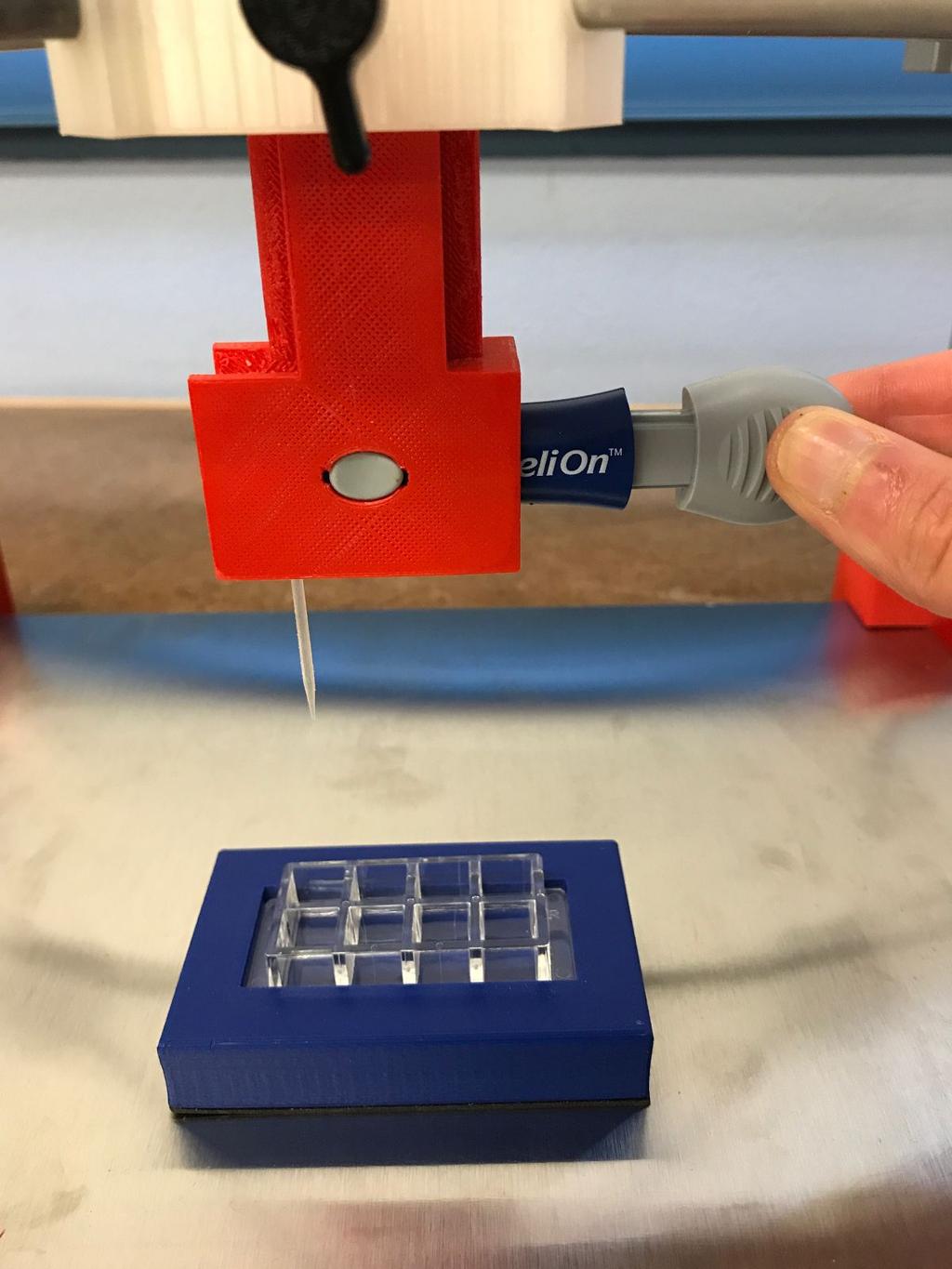
10 Step 12: Attach the top assembly onto the bottom assembly aligning the rods of the bottom assembly with the four remaining vertical holes of the top assembly. Step 13: Insert the z-axis holder into the top sliding piece and secure in place by tightening the butterfly knob on the top sliding piece. The frame of the device is now complete. Step 14: Place the Reli-On TM device in the Z-axis part as shown, with the grey button lined up with the hole in the device. 10


11 Step 15: Insert the needle into the needle holder as shown. 11


12 Step 16: Insert the needle holder into the end of the Reli-On TM device as shown. The device is now ready to be operated. 12
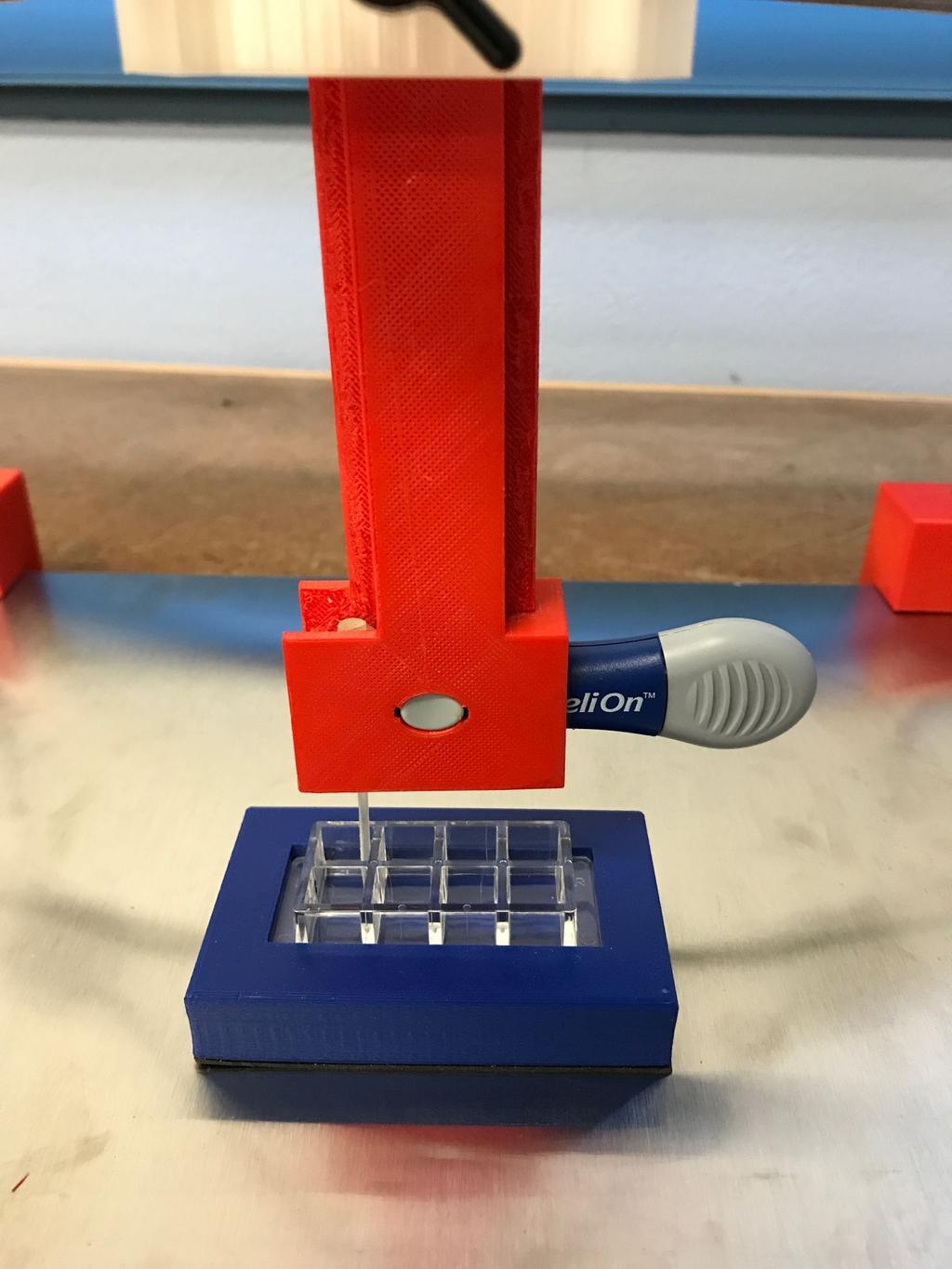
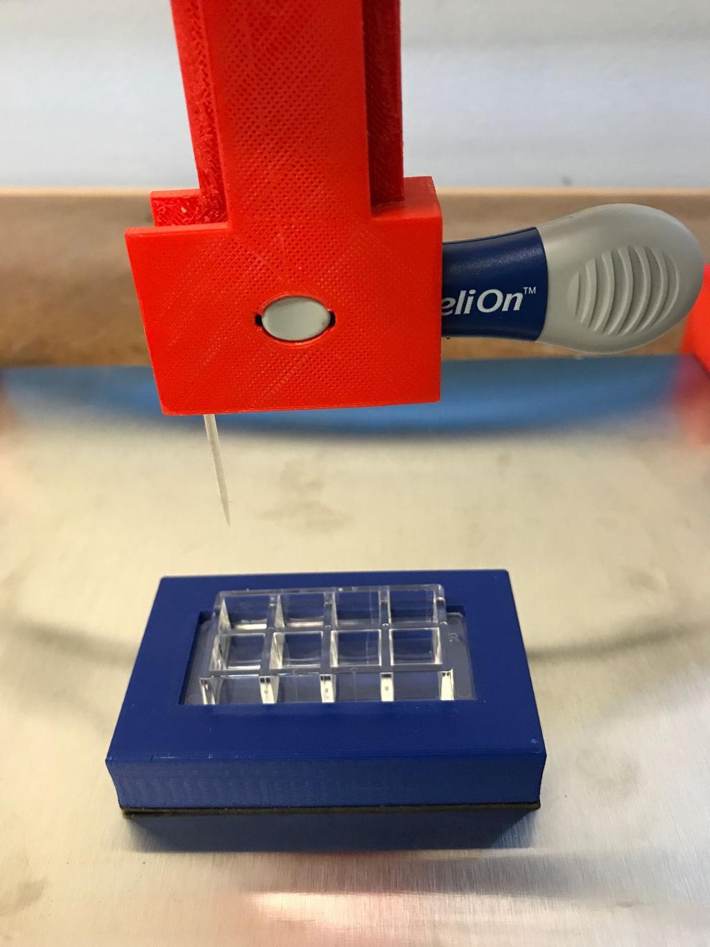
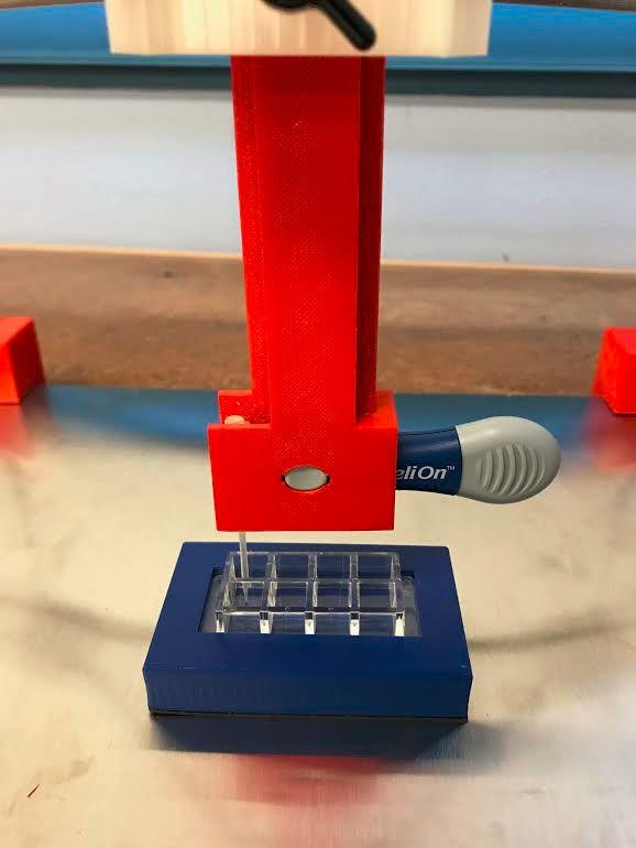
13 Comments: _ Operating the Device: Step 1: Place the well plate or Petri dish into the correct holder. Step 2: Pull back the plunger on the Reli-On TM device to load the needle. Step 3: Position the well plate holder on the magnetic platform so the needle of the scratcher is lined up with the well plate. Step 4: Loosen the butterfly knob and slide the Z-axis component down until the needle makes contact with the cells. Tighten the knob to lock the Z-axis component into place. Step 5: Press the grey button on the Reli-On TM device to propel the needle forward, creating a scratch in the cell monolayer. Step 6: Loosen the butterfly knob and move the Z-axis piece up, which will remove the needle from the well plate. Step 7: Sterilize the needle by dipping it into 70% ethanol, and allow it to evaporate. Step 8: Repeat steps 2-7 to perform another scratch. 13
14 Comments: _ Maintenance/Cleaning: Needle Replacement: The needle should only be used for about 50 scratches, therefore it is recommended that after 50 scratches the needle is replaced. 1. Remove needle holder from the Reli-On TM device. 2. Remove the used needle from the needle holder. 3. Place the new needle in the needle holder. 4. Reinsert the needle holder into the device. a. Remember that a calibration step must be done on the needle to ensure that accuracy of the device is maintained. 14
15 Z-axis Replacement: In the event that the z-axis piece is broken/ damaged it is recommended that it be replaced immediately in order to prevent skewed results. 1. Unscrew the butterfly knob to loosen the damaged z-axis piece from the top sliding piece. 2. Remove the scratcher unit from the damaged z-axis piece and then remove the z-axis piece from the top sliding piece. 3. Insert the new z-axis piece into the top sliding piece, and align the pieces, making sure that the tracks in the piece are able to easily move up and down. a. In the event that they do not allow free motion, make sure that the piece was properly installed. If it was not, remove and repeat step 3 from the beginning. 4. Screw the butterfly knob to lock the z-axis piece at the desired height. 15
16 Scratcher Unit Replacement: In the event that scratcher unit is damaged or no longer is generating a force to push the needle, it is recommended that the scratcher unit be replaced immediately. 1. Remove the needle holder from the scratcher unit (Reli-On TM ) device. 2. Remove the damaged scratcher unit from the z-axis movement piece. 3. Install the new scratcher unit: a. Place the new scratcher unit into the opening in the z-axis piece. b. Make sure that the push button is aligned with the opening on the z-axis piece, it should click into place. c. Make sure that the piece is secured within the z-axis piece, by gently moving it about to see if it will be easily removed 4. Reattach the needle holder to the new scratcher unit 5. Perform a scratch test without a sample to ensure that the scratcher unit is operating correctly. If device does not operate correctly redo from step 1. 16
17 Cleaning/Sanitization of the Needle: To sanitization the needle it is recommended that after each scratch the needle is dipped into 70% ethanol. 1. Adjust the height of the device using the z-axis piece. 2. Bring over a container of 70% ethanol and dip the visible parts of the needle into the ethanol. 3. Wait approximately 10 seconds to ensure that all the ethanol has evaporated. 4. Continue the procedure required to make a scratch in the further samples. WARNING: Do not attempt to sanitize the device using a flame technique. The 3D printed components will not withstand the heat a flame gives off, and they will melt. 17
18 Cleaning/Sanitization of the Whole Device: Recommended to clean the device after sample spills on the device or at least once a month to prevent contamination on the device. 1. Place the whole device in a separated area then spray down the device with a solution of 70% ethanol. 2. Do not saturate the device, just make sure that the whole device is lightly covered in the ethanol mist. 3. Wipe down the excess ethanol on the device and then allow the ethanol to evaporate from the device before the next use. WARNING: Do not put the device into an autoclave as can result in damage to device. The 3D printed components will not be able to withstand the high heat and pressure. 18

19 Comments: Glossary of Technical Terms: General Terms: In vitro scratch assay: An in vitro scratch assay is a method used to study cell migration patterns. The basic method is to create a wound in a cell monolayer by scratching through the cells. Upon scratching, the cells will migrate to close the gap. Definitions of Device Components: Needle: The needle is the component that makes contact with the cells and creates the scratch through the cell monolayer. Needle holder: The needle holder is the component where the needles are secured that interfaces with the spring loaded scratch mechanism. 19


20 Z-axis piece: Component of frame that houses the scratch mechanism and allows for height adjustment of scratcher. Scratcher Unit (Reli-On TM Device): Component that produces produces the spring force needed to move the needles. 20


21 Frame: The structure comprised of 3D printed parts and metal rods that provides structural stability for the scratcher. Platform: A steel base plate that doubles as structural support for the frame as well as a flat work surface to put well-plate holders on. Well Plate Holder(s): Plastic holders with magnetic bottoms prevent well-plates from moving as a scratch assay is performed. 21
22 Top Sliding Piece: Central component of frame where z-axis piece sits in. Comments: 22
23 Troubleshooting Z-axis piece: In the event that the Z-axis piece becomes damaged it is recommended that you contact a supervisor or request a new part. If current part is available see installation of Z-axis piece under maintenance/cleaning for instructions on page 15. Needle: In the event that the needle becomes damaged it is recommended that the needle be replaced immediately. Follow the procedure to replace needle, located on page 14. Scratcher unit: In the event that the scratcher unit malfunctions make sure that it is not jammed, if this does not fixed the issue it is possible that it is damaged. Therefore, go to the maintenance section and follow the procedure for scratcher unit replacement, located on page 16. Comments: _ 23
Replacing the Reciprocator on the SWF Compact Series Machine (601C and 1201C)
") Follow the instructions below to replace the reciprocator in the SWF Compact series machines. The tools required can be found in the tool kit that came with the machine. Preparation 1. First, place the
Follow the instructions below to replace the reciprocator in the SWF Compact series machines. The tools required can be found in the tool kit that came with the machine. Preparation 1. First, place the
Depending on the size you ordered you will have either 5 Foot sections which will build the 10 Foot frame or 6 Foot sections which will build the 12
 XL Quilting Frame 1 Depending on the size you ordered you will have either 5 Foot sections which will build the 10 Foot frame or 6 Foot sections which will build the 12 Foot frame Printed 2 June 2014 Updated
CHEMINSTRUMENTS LABORATORY DRAWDOWN COATER LC-100 OPERATING INSTRUCTION
 CHEMINSTRUMENTS LABORATORY DRAWDOWN COATER LC-100 OPERATING INSTRUCTION PRODUCT DESCRIPTION...2 UNPACKING...3 ASSEMBLY...4 Key Components...4 Set Up...5 OPERATION...5 MAINTANCE...7 WARRANTY...8 1 PRODUCT
AutoSeal FD 2006IL / FE 2006IL
 AutoSeal FD 2006IL / FE 2006IL FI / FJ Series 06/2018 OPERATOR MANUAL First Edition TABLE OF CONTENTS DESCRIPTION 1 SPECIFICATIONS 1 UNPACKING 1 SETUP 2 Sealer Alignment Base Setup 2 Sealer Setup 2-4
M4 Foot Operated Underpinner Instruction Manual
 M4 Foot Operated Underpinner Instruction Manual M4 Walker Rd, Bardon Hill, Coalville, Leicestershire LE67 1TU, England Tel. +44 (0)130 1692, Fax +44 (0)130 16929 e mail sales@framerscorner.co.uk M4 Underpinner
Maintenance & Parts list for:
 Maintenance & Parts list for: Industrial gun GB 2 Juni 2017 This Maintenance & Parts list for industrial gun is prepared by : Winchester Europe Service V. Parbst & Søn as a comprehensive maintenance guide
Arisaka Type 38 Rifle Disassembly and Reassembly
 Page 1 of 27 Arisaka Type 38 Rifle Disassembly and Reassembly Disassembly Instructions 1) Open the bolt as show in figure 1. Page 2 of 27 2) Open the bolt release. 3) Remove the bolt. 4) Remove the bolt/receiver
The Phoenix. Professional Quilting Frame. Copyright January 1, 2016 Jim M. Bagley, GraceWood, Inc (Reproduction Prohibited) Version 2.
 Version 2.") The Phoenix Professional Quilting Frame Copyright January 1, 2016 Jim M. Bagley, GraceWood, Inc (Reproduction Prohibited) Version 2.1 1 The Phoenix Professional Quilting Frame Parts List Box 1...3 Box
The Phoenix Professional Quilting Frame Copyright January 1, 2016 Jim M. Bagley, GraceWood, Inc (Reproduction Prohibited) Version 2.1 1 The Phoenix Professional Quilting Frame Parts List Box 1...3 Box
Owners Manual AGBAY Double Blade Levelers
 Owners Manual AGBAY Double Blade Levelers (20 Agbay & 12 Agbay Jr. ) Made in USA Lower Blade Adjustment Knob Stainless Adjustment Rod Stainless Steel Blades Upper blade frame Lower blade frame Scale for
FACTORY CAT TOMCAT CORPORATION
 FACTORY CAT RPS TOMCAT CORPORATION Artificial Turf and Carpet Sweeping Install Kit #349-641 & #349-642 1. Detach batteries so that there is no power running through the machine before starting. 2. Start
Hardware and Components:
 Hardware and Components: (A) 5/16 x 2 Hex Bolt (B) 5/16 x 2-1/4 Hex Bolt (C) 5/16 x 2-1/2 Hex Bolt (D) 4X 5/16 x 3/4 Hex Bolt (E) 4X 5/16 x 1-1/4 Hex Bolt (F) 11X 5/16 Flat Washer (G) 12X 5/16 Nylock Nut
FD 2002IL AutoSeal System
 FD 2002IL AutoSeal System 4/2017 OPERATOR MANUAL FIRST EDITION TABLE OF CONTENTS DESCRIPTION 1 SPECIFICATIONS 1 UNPACKING 1 SETUP 2 Sealer Alignment Base Setup 2 Sealer Setup 2-4 Printer Alignment Base
Sabre Series 2 Inspired Design Precision Engineering
 Sabre Series 2 Inspired Design Precision Engineering USER INSTRUCTIONS Thank you for choosing the Keencut Sabre Series 2. Every effort has been made to bring you a precision engineered product with the
Repairing Microsoft Wedge Touch Mouse Battery Cover Retaining Clip
 Repairing Microsoft Wedge Touch Mouse Battery Cover Retaining Clip Disassembly, repair and reassembly of Wedge Touch mouse when the battery cover will not stay closed. Also is a good guide to repair other
Removing outter components
 Y Axis Motor Replacement Replacing the Y axis motor is a process that requires the individual to be somewhat mechanically inclined and can follow detailed instructions. If any of the following steps are
B9Creator Build Table Calibration Process
 B9Creator Build Table Calibration Process Summary This document explains the process to calibrate the B9Creator Build Table. Things to Know The purpose of the Build Table calibration is to ensure the red
M*CARBO Winchester Model 70 Trigger Spring Kit Download or Print Instructions Contact: Page 1
 Download or Print Instructions Contact: help@mcarbo.com Page 1 Step 1: Clear your Firearm - Remove the magazine, check the chamber, bolt face and magazine well. Step 2: Gather Parts and Tools Needed Step
Steele TV Stand Stock # BH
 LOT NUMBER: DATE PURCHASED: / / Steele TV Stand Stock # BH46-084-899-02 ADULT ASSEMBLY REQUIRED If you have any questions regarding assembly or if parts are missing, DO NOT return this item to the store
High Rise Sit-Stand Desk Converter
 High Rise Sit-Stand Desk Converter Assembly Instructions for Model DC300 Patent Pending PRE-ASSEMBLY Please read all instructions before beginning assembly. We strongly recommend you watch the video at
Vinyl Cutter Instruction Manual
 Vinyl Cutter Instruction Manual 1 Product Inventory Inventory Here is a list of items you will receive with your vinyl cutter: Product components (Fig.1-4): 1x Cutter head unit complete with motor, plastic
HQ Hideaway. Installation and Operation Version 2.2, April 2015 Part # QT40100
 HQ Hideaway Installation and Operation Version 2.2, April 2015 Part # QT40100 Copyright 2015 Handi Quilter, Inc. All rights reserved. Printed in the U.S.A. Table of Contents Page Overview 3 To install
AutoSeal FD 2002/FD 2032 FE 2002/FE 2032 OPERATOR MANUAL FIRST EDITION
 AutoSeal FD 2002/FD 2032 FE 2002/FE 2032 10/2012 OPERATOR MANUAL FIRST EDITION TABLE OF CONTENTS SUBJECT PAGE DESCRIPTION 1 SPECIFICATIONS 1 UNPACKING 2 2000/2032 Components 2 Optional Conveyor Components
Quill Stop V2 Installation Guide 11/16/2014
 Thank you for purchasing the Quill Stop for the Sieg X3 (Grizzly G0463) and SX3 (Grizzly G0619) mills. Your feedback is always appreciated. Please email questions and comments to gregpriest@cox.net. What
Basic steps to time the Gammill quilting machine s rotary sewing hook
 Basic steps to time the Gammill quilting machine s rotary sewing hook 1.) Turn the machine off and unplug it. 2.) With the needle bar in the raised position, remove the bobbin and bobbin case. 3.) Remove
High Rise Sit-Stand Desk Converter
 High Rise Sit-Stand Desk Converter Assembly Instructions for Model DC350 Patent No. 9,332,839 PRE-ASSEMBLY Please read all instructions before beginning assembly. We strongly recommend you watch the video
Using Your Chip Priming Station
 Using Your Chip Priming Station The Chip Priming Station (5065-4401), is for use with the Agilent 2100 Bioanalyzer Analysis Kits. Refer to Figure 1 on page 2 for a picture of the Chip Priming Station.
Mechanical Frappe Press
 Mechanical Frappe Press Operation Manual CONTENTS OPERATIONAL INSTRUCTIONS PRECAUTIONS PART NAMES INCLUDED ITEMS BASIC OPERATION MAINTENANCE REPLACEMENT PARTS Thank you for using The Frapptastic Five Mechanical
INVENT3D Printer Kit Disassembly Instructions
 INVENT3D Printer Kit Disassembly Instructions Version 6 AST2 10/26/16 1 I. General Disassembly Instructions Use the case layer drawings to ensure that components are stored in the appropriate location
EXIT DEVICE OPERATION FIRE DOOR LABELS, STRIKES AND FRAME SCREWS FOR INFORMATION CALL OR VISIT RITEDOOR.COM
 RECORD & LABELS WHAT THIS OWNER'S CAN DO FOR YOU It explains exactly how The Rite Door operates. It explains periodic maintenance requirements necessary to assure reliable operation. It explains simple
DREAMOC XXL3 - ASSEMBLY GUIDE VERSION ORIGINAL ASSEMBLY GUIDE
 DREAMOC XXL3 - ASSEMBLY GUIDE VERSION 1.3 - ORIGINAL ASSEMBLY GUIDE It is important to read this assembly guide before using the Dreamoc, and to follow advices and instructions on safety, operation and
Hardware and Components:
 Hardware and Components: (A) 4X 5/16 x 1 Carriage Bolt (B) 2X 5/16 x 2-1/4 Carriage Bolt (C) 2X 5/16 x 3-1/4 Hex Bolt (D) 2X 5/16 x 3/4 Hex Bolt (E) 2X 5/16 x 1-1/4 Hex Bolt (F) 5/16 x 2-1/4 Hex Bolt (G)
ABM International, Inc.
 ABM International, Inc. Lightning Stitch required 1 1.0: Parts List head and motor assembly (Qty. 1) Reel stand (Qty. 1) Needle bar frame clamp (Qty. 1) Motor drive (Qty. 1) 2 Cable harness with bracket
Replacing the Reciprocator on an SWF Multi-head.
 Replacing the Reciprocator on an SWF Multi-head. Follow the instructions below to replace the reciprocator in the SWF multi-head machines. The tools required are found in the tool kit that came with the
Operator s Manual. Onion King 500N 501N 502N 503N ENGLISH
 Onion King 500N 501N 502N 503N Thank you for purchasing this Vollrath Food Processing Equipment. Before operating the equipment, read and familiarize yourself with the following operating and safety instructions.
Technical description
 STAHLWILLE Standard Manoskop 721 Service Manoskop 730 List of contents Technical description... 27 ã=important safety points... 30 Operation... 32 Maintenance... 42 Cleaning the Manoskop... 47 Accessories...
TIP FOR GETTING STARTED
 Tip for getting started TIP FOR GETTING STARTED Be careful not to drill into any electrical wires, ductwork, plumbing or other damagable components. If you have any questions on the locations of these
AUC Cell Assembly Torque Stand. User Manual
 AUC Cell Assembly Torque Stand User Manual WARRANTY Spin Analytical Inc., warrants this product to be defect free in both material and workmanship for 90 days from the date of shipment. Labor services
Electron Microscopy Sciences
 Electron Microscopy Sciences INSTRUCTIONAL MANUAL CAT. #7670 FlipScribe P.O. Box 550 s1560 Industry Road s Hatfield PA 19440 1 Overview The FlipScribe enables cleaving through frontside targets with a
Installers guide Deadbolt 02.
 Installers guide Deadbolt 02. version 0.7.1 Specifications Model igloohome Smart Deadbolt 02 Material Zinc Alloy Current Rating (Standby) ~30uA Current Rating (Active) ~200mA Batteries 4 x AA Alkaline
INSTALL INSTRUCTIONS WELCOME TO THE NEWAGE PERFORMANCE CABINETRY SERIES NEWAGE STEEL WELDED CABINETRY
 NEWAGE STEEL WELDED CABINETRY WELCOME TO THE NEWAGE PERFORMANCE CABINETRY SERIES ALL CABINETS MUST BE MOUNTED TO STUDS ON A SECURE WALL, AS PER THESE INSTRUCTIONS. FAILURE TO DO SO MAY RESULT IN SERIOUS
Fan, Eden/Northfield, GS Installation Instructions (SKU ) Packing List
 Packing List") Packing List Blower Assembly Wiring Harness Rheostat with Nut and Knob Snap Disc Mounting Hardware (4) rubber grommets with brass inserts, (4) nuts, (4) washers. Cover Assembly Installation Warning: Make
Packing List Blower Assembly Wiring Harness Rheostat with Nut and Knob Snap Disc Mounting Hardware (4) rubber grommets with brass inserts, (4) nuts, (4) washers. Cover Assembly Installation Warning: Make
BIFOLD FUTON FRAME TRINITY ARM. Seat Rails and Slats x 1. *Note: Use 4pc of 100mm Bolts and 4pc of 60mm Bolts to attach the arms to the Stretchers.
 1A Parts in this box. 2pc with extra holes 2pc with extra holes & plastic stoppers Arms x 2 Back Rails and Slats x 1 Full Size: Slat Supports x 6 3pc are longer for the Back deck Back Side Rails x 2 Seat
Inde-Pendants Family. 32L Ring Plaster Trim, Grid and Drywall Ceiling Types. Document No Installation instructions for 32L-Rxx-P
 Inde-Pendants Family 32L Ring Plaster Trim, Grid and Drywall Ceiling Types Installation instructions for 32L-Rxx-P Document No. Supplied by Litecontrol 32L Inde-Pendants: Ring (Plaster Trim, Grid and Drywall
AUTOMATIC ADVANCE MANUAL
 AUTOMATIC ADVANCE MANUAL AVL Looms, Inc. 3851 Morrow Lane, Suite #9 Chico, CA 95928-8305 530 893-4915 530 893-1372 fax # info@avlusa.com www.avlusa.com Copyright 2009 TABLE OF CONTENTS Page # I. Parts.........................
Setting up and Using Digital Micrometer Controlled Lapping Fixtures
 Setting up and Using Digital Micrometer Controlled Lapping Fixtures Purpose polishing fixtures are commonly used in materials preparation labs around the world. Lapping fixtures provide stability, precision,
Assembly and Installation Guide
 The Easy Hang Closet Solution SM Install Your elfa In An Instant. Enjoy The Benefits For A Lifetime. Basic Tools For elfa Assembly and Installation Level Hand or Power Drill Drill Bits 1/8", 3/8", 5/16"
Owners Manual AGBAY Single Blade Levelers (20 Agbay & 12 Agbay Jr.)
") Owners Manual AGBAY Single Blade Levelers (20 Agbay & 12 Agbay Jr.) Made In USA Adjustment Knobs Adjustment Rod Frame Stainless Steel Blade Stainless Steel Scales Feet Blade Guard Jr. Model Shown Agbay
Owners Manual AGBAY Single Blade Levelers (20 Agbay & 12 Agbay Jr.) Made In USA Adjustment Knobs Adjustment Rod Frame Stainless Steel Blade Stainless Steel Scales Feet Blade Guard Jr. Model Shown Agbay
Z-Truck Up-and-Down Motion. Y-Truck Side-to-Side Motion. Head. Squaring Plate. Sliding Plate FIGURE 1: THE CARVEWRIGHT MACHINE
 Setup and use of CarveWright CO2 Powered Dragster Jig The CO 2 powered Dragster Jig will arrive from the factory fully assembled, calibrated, and squared. In order to get the best results, your CarveWright
Midwest RDH Handpiece Repair Procedure
 Midwest RDH Handpiece Repair Procedure The Midwest RDH handpiece is fairly common and is used by hygienists to clean teeth. The most common problems for this handpiece include a bad prophy head or a dirty
Installation Manual Porter Road, Sarasota FL fax
 072015 Installation Manual BEFORE YOU BEGIN: Read these instructions completely and carefully. FOR YOUR SAFETY: Read and observe all CAUTIONS and WARNINGS shown throughout these instructions. Risk of injury.
Standard Operating Procedure
 RIT MULTIDISCIPLINARY SENIOR DESIGN 2010 Standard Operating Procedure Baja Water Propulsion Test Stand This SOP specifies how to assemble, use, troubleshoot, and disassemble the water propulsion system
INSTALLATION MANUAL FORTRESS SERIES
 Guardian Security Structures TEL 1-406-212-2334 EMAIL rg@gssdoors.com WEB www.gssdoors.com FORTRESS SERIES GENERAL INSTALLATION GUIDELINES 1. The door frame is installed using 16 bolt screws 7,5 mm in
Installing Brackets to Minimize Distortion in Your SMART Board 685ix Interactive Whiteboard System s Projected Image
 UX60-RFK-685 Installing Brackets to Minimize Distortion in Your SMART Board 685ix Interactive Whiteboard System s Projected Image Follow these instructions to install brackets on your SMART Board 685ix
PT50A Industrial, PT50B & PT50C Sharp
 Instructions For Use of Your PT50A Industrial, PT50B & PT50C Sharp Edge Sharpness Tester manufactured by Pictured PT50B Thank you for purchasing a PT50 Series Sharp. From now on you will know with precision
INSTALLATION GUIDE 2009-CURRENT HUMMER H3T PRODUCT CODE:
 INSTALLATION GUIDE 2009-CURRENT HUMMER H3T PRODUCT CODE: 268 June 22, 2010 TOOLS NEEDED COMPONENTS INCLUDED P2 Tip 3/8" Drill Rubber Gasket(s) x 2 Bracket(s) x 2 1/2" Drill Bit Bulkhead Flange #2 Phillips
Assembly Guide for Printrbot - Simple Maker s Edition 1405
 Assembly Guide for Printrbot - Simple Maker s Edition 1405 Last update: March 2016 Please Note: be careful on the steps that are underlined 1 Contents Tools Needed:... 3 First step: Check components and
RULTRACT RETRACTOR CABLE REPLACEMENT INSTRUCTIONS. Rultract, Inc. is the ONLY authorized service center in the U.S.A.
 RULTRACT RETRACTOR CABLE REPLACEMENT INSTRUCTIONS Rultract, Inc. is the ONLY authorized service center in the U.S.A. When your Rultract instrument needs repair or service, contact Rultract Inc. or Rultract
INSTRUCTIONS Crown Molding and Trim Protractor Used to cut trim lying flat
 Wixey TM MODEL CJ4000 INSTRUCTIONS Crown Molding and Trim Protractor Used to cut trim lying flat Measures and calculates the compound miter and bevel angles for cutting crown molding and trim. Features:
General Wood Shop Notes
 General Wood Shop Notes Restricted Materials No METAL or BONE of any kind on any machine or in the room o See additional restrictions individual machine All reclaimed and other than new lumber must be
Balishutters. INSTALLATION guide FOR L-FRAME MOUNT INSTALL OPTIONS B OR C
 Balishutters INSTALLATION guide FOR L-FRAME MOUNT INSTALL OPTIONS B OR C Tools needed for installation Drill Phillips bit 1/8" drill bit 4. Hammer (preferably hard plastic) 5. Level 6. Phillips-head screwdriver
Step 1: The larger tower box contains the tower machine, a set of Silver 100 Lid Keys, and a set of Black 002 Coin Box Keys
 2 3 Step 1: Each tower is shipped as two boxes the large tower box and the smaller stand box. Open each of the boxes and inventory each of the parts before starting assembly to ensure all parts have arrived.
Please Do Not Return Your Item to the Retailer
 Please Do Not Return Your Item to the Retailer Thank you for your purchase of an Epic Furnishings item You should enjoy many years of trouble free, dependable use If for any reason you are missing parts,
The Useless Machine. DIY Soldering Edition. Instruction Guide v0004
 The Useless Machine DIY Soldering Edition Instruction Guide v0004 TM For the best outcome, follow each step in order. We recommend reading this guide entirely before you get started. Tools required: Soldering
The Useless Machine. Parts Only - Build Guide v0001
 TM The Useless Machine Parts Only - Build Guide v0001 For the best outcome, follow each step in order. We recommend reading this guide entirely before you get started. Tools required: One phillips screwdriver,
CABINETRY Assembly Instructions
 www.hdicabinetry.com Assembly Instructions TABLE OF CONTENTS Category Page(s) Section 1: Framed Series Base Cabinet Instructions Wall Cabinet Instructions Easy Reach Cabinet Instructions 1.01-1.04 1.05-1.06
Javelin Integra Inspired Design Precision Engineering
 Javelin Integra Inspired Design Precision Engineering USER INSTRUCTIONS Thank you for choosing the Keencut Javelin Integra. Every effort has been made to bring you a precision engineered product with the
Due to possible damage in shipping, the vertical stop assembly has been removed from this machine.
 Due to possible damage in shipping, the vertical stop assembly has been removed from this machine. To assemble, insert the threaded rod through the shroud opening in the top of the machine. Start the four
For additional assistance call
 The following pages will help guide you through the process of assembling your new 48 custom prize wheel. Choose an assembly area with plenty of room to lay your pieces on the floor and also a bench or
SCITEX Dual Roll Kit. User s guide
 SCITEX Dual Roll Kit User s guide 2011 Hewlett-Packard Development Company, L.P. First edition Legal notices The information contained herein is subject to change without notice. The only warranties for
Vanity Installation Instructions
 Vanity Installation Instructions Segments of these instructions will relate to your vanity. Please read these instructions thoroughly and ensure the appropriate instructions are used during the installation
Studio Face Xtreme 6020 Installation Instructions (Nickel , Black )
") Packing List Face Trim (4 Pieces) (3) Hanging Brackets (9) 3/16 x 1-1/4 Masonry Screws 9/64 Drill Bit Compatibility (2) Lower Brackets w Magnets (2) Lower Facing Plates (4) 2 Drywall Screws Trim Hardware
Packing List Face Trim (4 Pieces) (3) Hanging Brackets (9) 3/16 x 1-1/4 Masonry Screws 9/64 Drill Bit Compatibility (2) Lower Brackets w Magnets (2) Lower Facing Plates (4) 2 Drywall Screws Trim Hardware
Chapter 6 Frame And Lens Repairs
 Chapter 6 Frame And Lens Repairs 6.1 General Information All maintenance on the frame of the EXO Full-Face mask can be accomplished with common hand tools. 6.2 Lens Replacement Tools required: Dow DC-111
CHICKEN COOP & CHICKEN RUN. Tools required for assembly (not included)
") CHICKEN COOP & CHICKEN RUN ASSEMBLY MANUAL SKU# 6839 Tools required for assembly (not included) Distributed by: TRACTOR SUPPLY COMPANY 0 VIRGINIA WAY, BRENTWOOD, TN 3707 For customer support, call: -888-376-960
CHICKEN COOP & CHICKEN RUN ASSEMBLY MANUAL SKU# 6839 Tools required for assembly (not included) Distributed by: TRACTOR SUPPLY COMPANY 0 VIRGINIA WAY, BRENTWOOD, TN 3707 For customer support, call: -888-376-960
SPRINT 5000 BOOKLETMAKER OPERATION MANUAL
 SPRINT 5000 BOOKLETMAKER OPERATION MANUAL Sprint5000HCS-USA.doc3.doc Page 1 01/05/2002 CONTENTS 1. Introduction. 2 2. Specification. 2 3. Initial setting up. 3 4. Operation. 4 4.1 Loading staples. 5 4.2
U.S. Rack, Inc Falcon Drive, Madera, CA APR17 INSTALLATION AND USE INSTRUCTIONS for SIDE-MOUNT LADDER RACK
 U.S. Rack, Inc. 2850 Falcon Drive, Madera, CA 93637 15APR17 INSTALLATION AND USE INSTRUCTIONS for SIDE-MOUNT LADDER RACK WARNING: Do NOT attempt to install or use this rack without following all instructions.
Lunette Series. Home Theater Curved Fixed Frame Projection Screen. User s Guide. Important Safety and Warning Precautions
 Lunette Series Home Theater Curved Fixed Frame Projection Screen User s Guide Important Safety and Warning Precautions Please follow these instructions carefully to ensure proper maintenance and safety
ASSEMBLY INSTRUCTIONS FOR SL500A AND SL500AL
 ASSEMBLY INSTRUCTIONS FOR SL500A AND SL500AL January 2013 The SL500A is a square upright glass cabinet with a single hinged lockable door. It has five adjustable shelves plus the base. It also has an optional
G. H. I. N. J. O. 22"x 28" Poster Holder. P. Q. romotional wall displ
 Wall Display Assembly Instructions Tools necessary for assembly 1. Electric drill with Phillips head 2. Adjustable wrench or pliers 3. One or two step ladders or stools Due to the weight of the side panels
POWER PET. Low-E Automatic Patio Pet Door Installation and Operating Instructions
 POWER PET Low-E Automatic Patio Pet Door Installation and Operating Instructions Power Pet, Regular Height, Patio Door Assembly Steps Estimated assembly time: Under 1 hour STEP 1: Assemble the tools you
Hydrajaws Safety Lifeline Tester
 Hydrajaws Safety Lifeline Tester Operating Instructions HYDR AJAWS LIMITED Hydrajaws Safety Lifeline Tester 4 5 1 6 7 2 3 9 10 8 12 11 TECHNICAL SPECIFICATIONS Load Gauges Range available: Analogue: 0-25kN/lb/f
FBX1104P FBX1104 FBX1106P FBX1106
 FBX1104P FBX1104 FBX1106P FBX1106 Second edition : September 2004 No. 040037 INTRODUCTION Thank you for your purchasing Kansai Special's FBX Series. Read and study this instruction manual carefully before
Fig. 2 DORMA-Glas Stand/Issue 02/03 Seite/Page 1/7
 FSW Installation instructions Track rail 75 x 72 mm 1. Ceiling substructure and installation of the track rail (Fig. 1): The track rail must be bolted over its entire length (including the stacking track
First published : May 1997 Fourth edition : January No
 First published : May 1997 Fourth edition : January 2006 No. 050153 INTRODUCTION Thank you for your purchasing Kansai Special's FX Series. Read and study this instruction manual carefully before beginning
Hollywood Swing Away 2 and 4 Bike Racks Assembly and Installation Guide
 Hollywood Swing Away 2 and 4 Bike Racks Assembly and Installation Guide Tools Required: two adjustable wrenches, pliers, ¾ socket wrench recommended Note: please do assembly near your vehicle as you Can
Bath Accessory Installation
 Bath Accessory Installation Step 1 - Clean surface using a clean dry cloth or use rubbing alcohol to remove any residue (wax, grease, solvents). Allow to dry one hour. Caution! DO NOT use any household
504P Operator s Booklet
 504P Operator s Booklet Visit our Web site at http://www.rhinovending.com/ Copyright 2011 by Rhino Vending. All rights reserved. No portion of this manual or any artwork contained herein may be reproduced
Strata. urniture. Adriana Instructions. Parts in the Arm Box: Parts in the Body Box: Watch our assembly videos at
 1A Watch our assembly videos at www.strataf.com/videos Parts in the Arm Box: Arm - Outside View Arm - Inside View 1B Parts in the Body Box: Back Deck x 1 Seat Deck x 1 with the Feet attached Back Panel
A-dec 574L and 575L Dental Lights on a Cabinet or Wall INSTALLATION GUIDE
 A-dec 574L and 575L Dental Lights on a Cabinet or Wall INSTALLATION GUIDE A-dec 574L Dental Light Mounted on an A-dec Inspire TM 59 Central Console Before You Begin. Turn off the power to the system before
a.k.a. casegoods instructions
 a.k.a. casegoods instructions a a.k.a. workwall installation IMPORTANT NOTES Failure to install product according to installation instruction will result in loss of warranty. Tools required for assembly
SAVE THESE INSTRUCTIONS
 SAVE THESE INSTRUCTIONS SONOMA 10.5 FT CANTILEVER UMBRELLA ASSEMBLY INSTRUCTIONS ASSEMBLE ON A FLAT, PROTECTED SURFACE. PART LIST FIGURE QUANTITY DESCRIPTION A LOWER BRACKET B UPPER BRACKET C BASE POLE
Maintenance Information
 16601023 Edition 2 January 2014 Air Impact Wrench 2705P1 Maintenance Information Save These Instructions Product Safety Information WARNING Failure to observe the following warnings, and to avoid these
SEWING MACHINE For use with Janome HD 1000
 SEWING MACHINE For use with Janome HD 1000 YALE CENTER FOR ENGINEERING INNOVATION AND DESIGN Table of Contents p. 3-5... Winding the Bobbin p. 6-7... Threading the Bobbin p. 8-10... Threading the Needle
ABSL Model Background Stand
 ABSL Model Background Stand Product Overview: The Ravelli ABSL model background stand is adjustable up to 13' tall by 15' wide. It is comprised of two tripod stands and five 3 cross bar sections and includes
Installation Guide. Mounting Kit for Mounting Philips Avalon CTS Cordless Fetal Transducer System on Wall, 2'' Post, Rail, or Slide-on Mounting Plate
 Installation Guide Mounting Kit for Mounting Philips Avalon CTS Cordless Fetal Transducer System on Wall, 2'' Post, Rail, or Slide-on Mounting Plate The purpose of this guide is to: 1. Describe mounting
MULTI-ACTIVITY PLAY TABLE
 ASSEMBLY INSTRUCTIONS! WARNING: CHOKING HAZARD - Small parts. Not for children under 3 years.! CAUTION: Adult assembly required. C 2006 Melissa and Doug, Inc. All Rights Reserved www.melissaanddoug.com
Step by Step Installation Instructions. Poly Shutters. Customer Service or visit us online at smithandnoble.com
 Step by Step Installation Instructions Poly Shutters Customer Service 800.248.8888 or visit us online at smithandnoble.com Thank you for purchasing from smith+noble. Your new window treatments have been
HP-2 / HP-4 Wall Wash Recessed Spackle & Visible Flange Installation Instructions Overview
 Overview NOTES All power connections should be installed according to local/national codes by a Certified Electrician. This installation requires proper support as each luminaire is being installed. DO
FABA. Installation Instructions. Conductor Bar System. Publication #FABA-03 3/1/04 Part Number: Copyright 2004 Electromotive Systems
 FABA Conductor Bar System Installation Instructions Publication #FABA-03 3/1/04 Part Number: 005-1062 Copyright 2004 Electromotive Systems 1S 100 Z Installation Instructions Contents: Basic Diagram - -
Mount to the Wall INSTALLATION MANUAL
 Mount to the Wall 15 Locate the Wooden Studs This step applies to wooden stud wall installation only. Determine and mark the exact locations of two stud centers on the wall. Wooden studs should be spaced
WARNING: Wear safety goggles at all times when the engine is running and cooling
 WARNING: Wear safety goggles at all times when the engine is running and cooling Please be safe and enjoy your engine. It is not a child's toy it is a precision machined working model. Never leave Children