POWER PET. Low-E Automatic Patio Pet Door Installation and Operating Instructions
|
|
|
- Daniel Stone
- 5 years ago
- Views:
Transcription

1 POWER PET Low-E Automatic Patio Pet Door Installation and Operating Instructions
 drill bit 4. 3/32 drill bit 5. 1/4 drill bit 6. Scissors 7. Tape Measure 8. Pencil 9. Safety Glasses STEP 2. Unpack your door Remove all parts from box.")
 6. Weather Stripping 7. Draft Stopper Seal 8. Section Connectors (2) 9. Door Lock Housing (1) 10.")
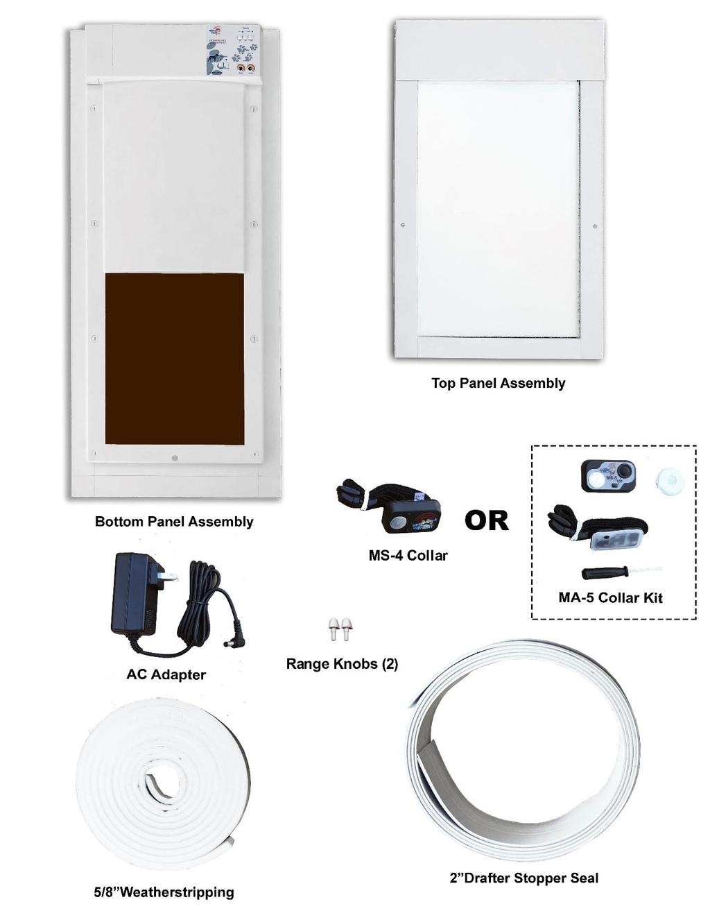
2 Power Pet, Regular Height, Patio Door Assembly Steps Estimated assembly time: Under 1 hour STEP 1: Assemble the tools you will need: 1. Size #1 Phillips screwdriver 2. Electric drill 3. #32 (.117 ) drill bit 4. 3/32 drill bit 5. 1/4 drill bit 6. Scissors 7. Tape Measure 8. Pencil 9. Safety Glasses STEP 2. Unpack your door Remove all parts from box. Plastic corner protectors may be discarded. Figure 1 STEP 3: Lay Out All Included Parts Your door contains all of the parts shown in Figures 3A and 3B and listed below. 1. Bottom Panel Assembly with PX-2 Power Pet Door 2. Top Panel Assembly 3. MS-4 Ultrasonic Collar or MS-5 Collar Kit 4. AC Adapter 5. Range Knobs (2) 6. Weather Stripping 7. Draft Stopper Seal 8. Section Connectors (2) 9. Door Lock Housing (1) 10. Lock Handle (1) 11. Lock Hasp (1) 12. House Lock Tab (2) 13. Vacation Lock (1) 14. Rectangular Hole Plug (1) 15. Round Hold Plug (2) 16. 1/16 Allen wrench 17. 1/8 Allen wrench 18. 1/4-20 X 1/2 flat head machine screw (8) 19. #8 X 5/8 round head sheet metal screw (4) 20. #6 X 1/2 round head sheet metal screw (6) 21. #4 X 3/8 flat head sheet metal screw (4) 2 Figure 2
3 Fig 3A 3
4 Figure 3B 4 4

5 Basic Door Assembly May be placed on left or right side of Patio Pet Door assembly. Fig 3A Figure 3C 5
 77 80 1/4 Do Not Remove Riser Extension (Skip Step 5) Fig 4 STEP 5: For short installations, remove Riser Extension If")

6 STEP 4: Determine your patio track height Measure from the inside bottom of your sliding glass door track to the inside top as shown in Figure Remove Riser Extension (Step 5) /4 Do Not Remove Riser Extension (Skip Step 5) Fig 4 STEP 5: For short installations, remove Riser Extension If your sliding glass door frame measures between 75 and 77 high, remove the Riser Extension on the Bottom Panel Assembly by unscrewing the connector screws on each side of the Riser Extension as shown in Figure 5. The aluminum Riser Extension may be recyled. For patio doors taller than 77, do not remove the extension. 6 Fig 5
 1/4-20 X 1/2 flat head machine screws for each Section Connector as shown in")

 1/4-20 X 1/2 flat")
7 STEP 6: Insert Section Connectors Insert Section Connectors on the Bottom Frame Assembly panel using (2) 1/4-20 X 1/2 flat head machine screws for each Section Connector as shown in Figure 6. Fig 6 STEP 7: Put Top and Bottom Panel Assemblies together Insert Top Frame Assembly on to Bottom Frame Assembly as shown in Figure 7. STEP 8: Install Section Connector screws Screw panels together using (2) 1/4-20 X 1/2 flat head machine screws for each Section Connector. The Top and Bottom Frame Assemblies now form a single Door Panel as shown in Fig 8. Fig 7 Fig 8 7


. Tilt the pet door assembly up. (Fig 10B). pull down on the Top Slider.")

8 STEP 9: Loosen the Top Slider set screws Loosen the Top Slider locking set screws on the left and right sides of the Top Panel Assembly using the 1/8 Allen wrench provided. If the Top Slider does not immediately release, push it up by hand so that it slides to its highest position. STEP 10: Insert the patio pet door into your sliding glass door track Fig 9 Fig 10A Fig 10B Fig 10C Make sure the lock holes in the Top Frame Assembly are facing the inside of your home. Position the pet door assembly into your sliding glass door frame by first inserting the pet door Bottom Panel into the bottom of your door track so that the Simi-circular groves in the pet door Bottom Panel are placed over the sliding rail at the base of your sliding glass door track (Fig 10A). Tilt the pet door assembly up. (Fig 10B). pull down on the Top Slider. Insert the Top Slider into the top of your door track and release, allowing it to move up into the top of the track. STEP 11: Install a House Lock Tab on the Top Panel Assembly Install a House Lock Tab on the wall side of the pet door by screwing (2) #6 X ½ round head sheet metal screws into the pre-drilled holes on the pet door. Position the Tab with the open end pointing downward as shown. Fig 11 8

.")

 holes into your door track using a 1/16 drill bit.")
9 STEP 12: Mark the height of the House Lock Tab on your sliding glass door track Measure from the sliding rail at the base of your door track to a height of 46 5/8 if you are using the Riser Extension or 44 5/8 if you are not using the Riser Extension. Mark this height on the inside of your door track (Figure 12A). Remove the tape liner from a House Lock Tab and Position the top of the non-drilled end at this mark.as shown in Figure 12B. Fig 12A Fig 12B STEP 13: Drill the Lock House Tab mounting holes in your sliding glass door track Drill (2) holes into your door track using a 1/16 drill bit. Fig 13 STEP 14: Screw in the Lock House Tab Screw the Lock House Tab to your door track using (2) #6 X 1/2 screws. Fig 13 9 Fig 14


10 STEP 15: Insert Round Hole Plug(s) The purpose of the Round Hole Plugs is to fill the unused Lock Knob hole. Lock Knob holes are provided on both sides of the Top Panel Assembly for left and right opening sliding glass doors. When using the Universal Lock Assembly, one Lock Knob hole will not be used. Install a Round Hole Plug in the unused Lock Hole on the side of the pet door assembly which butts against your sliding glass door track. This is the side that does not require the lock. If you chose not to use the Universal Lock Assembly, install a Round Hole Plug in both Lock Knob Holes. Fig 15 STEP 16: Engage the House Lock Tabs Fig 16A Fig 16B Slide the assembled pet door so that it butts up against the inside of your sliding glass door track. Firmly grab the pet door from the inside and outside. Lift up and push against the sliding glass door track letting the House Lock Tabs engage each other as the door frame drops into its final position. 10


11 STEP 17: Tighten the Top Slider set screw Once your Door Assembly is in place, you will have access to the Top Slider Set Screw on the side facing your sliding glass door. Tighten the set screw using the 1/8 Allen Wrench. This will lock the Top Slider in place. Fig 17 STEP 18: Insert Rectangular Hole Plug if you are NOT using the Universal Lock Assembly If you choose not to use the Universal Lock Assembly, install the Rectangular Hole Plug in the lock cavity on the open side of the assembled door panel. This will allow you to apply weather stripping over the cavity. If you will be installing the Universal Lock, skip this step and proceed to Step 19. Fig 26A Installing Rectangular Hole Plug Fig 26B Installed Hole Plug gives you a flush surface to apply Fig 26 weather stripping INSTALLING THE UNIVERSAL LOCK ASSEMBLY The universal lock assembly allows you to quickly lock your sliding glass door with the patio pet door installed. It requires that you drill 2 small holes in the edge of your sliding glass door. 11


12 STEP 19: Insert the Door Lock Housing Insert Door Lock Housing on the open side of the assembled pet door panel so that the Lock Arm is in the up position when open as shown in Figure 15. Fig 19 STEP 20: Install the Lock Knob Install the Lock Handle so that the handle is vertical when the lock is open (Lock Arm is in up position.) and so that one of the detents in the Lock Handle shaft aligns with the Lock Arm Set Screw. Turning the Lock Handle counterclockwise should move the Lock Arm to the closed position. If the Lock Knob does not easily insert into the Lock Arm, loosen the Lock Arm Set Screw. Fig 20 Note that there are (2) detents in the Lock Knob for left and right opening door opening sliding glass doors. Make sure the handle is oriented vertically and that one of the detents aligns with the Lock Arm Set Screw. STEP 21: Tighten the Lock Arm set screw Tighten the Lock Arm set screw using the 1/16 Allen wrench provided. Note that there should be a sight gap between the Lock Knob and the patio pet door panel when the unit is assembled correctly. 12 Fig 21


13 STEP 22: Insert Lock Hasp into the Door Lock Housing Insert the Lock Hasp into the Door Lock Housing as shown in Figure 22A. Note that it is important that the vertical orientation of the Lock Hasp is as shown in the figure. Turn the Lock Handle counterclockwise so that the Lock Hasp is trapped in the Door Lock Assembly. Then, remove the protective liner from the tape on the back of the Lock Hasp. Fig 22A Insert the Hasp into the Lock Housing as shown Fig 22B Turn the Lock Knob counterclockwise to trap the Hasp Fig 22C Remove the tape backing STEP 23: Transfer the Lock Hasp to your sliding door Slide your patio door closed so that the Lock Hasp tape makes contact and affixes to the sliding glass door. Turn the Lock Handle clockwise, releasing the Lock Hasp and open your sliding glass door. The Lock Hasp should now be affixed to your sliding glass door. Fig 23A Close your sliding glass door so that the tape on the Lock Hasp attaches to your door Fig 23B Turn Lock Knob clockwise and open your sliding glass door 13
 #6 X 1/2 round head sheet metal screws.")


14 STEP 24: Drill Lock Hasp mounting holes Using the 3/32 drill bit drill (2) holes within the slots of the Lock Hasp. Fig 26 STEP 25: Screw Lock Hasp to your sliding glass door Attach the Lock Hasp to your sliding glass door with (2) #6 X 1/2 round head sheet metal screws. Fig 24 STEP 27: Apply Weather Stripping Peal the adhesive backing from the first 2 inches of the weather stripping. Starting at the bottom, apply the weather stripping to the inside edge of the open side of the assembled door panel removing the adhesive backing as you move up. Fig 25 If using the Universal Lock Assembly, cut at the bottom of the lock and restart above the lock. Continue to the top of the Top Frame Assembly and cut. INSTALLING THE VACATION LOCK The Vacation Lock provides added security when away from your home for extended periods. It requires drilling a 1/4 hole at the bottom of your stationary patio door and 2 small holes in your sliding glass door. If you choose to use the Vacation Lock. Follow STEPS If not, proceed to Step Fig 27


15 STEP 28: Drill the Vacation Lock bolt hole Position the Vacation Lock on the edge of your sliding glass door at the top or bottom with the Locking Bolt extended. The end of the bolt should be facing your stationary door track as shown in Figure 30. Using a pencil, trace around the circumference of the bolt on the stationary sliding glass door frame. Then Remove the Vacation Lock and mark the approximate center position of the bolt. Drill a 1/4-inch hole in your stationary sliding glass door frame for the bolt. Fig 28A Position the lock and mark the bolt position Fig 28AB Mark the bolt center Fig 28C Drill the bolt hole STEP 29: Drill the Vacation Lock mounting holes The Vacation Lock provides added security. It may be attached to you sliding glass door at the top or bottom. With the bolt extended and inserted into the drilled hole, position the Vacation Lock onto edge of your sliding glass door and, with a pencil, trace the slots of the Vacation Lock onto the edge of your sliding glass door. Note: Before drilling, Retract the bolt and make sure there is clearance between the retracted bolt and your stationary door frame. Reposition the Vacation Lock if necessary, to make sure there is clearance but, also making sure that the bolt is still centered on the hole. Drill (2) holes in your sliding glass door using a #32 drill bit, one hole in the center of each of the slots you marked. Fig 29A Trace the 2 lock slots Fig 29B Marked slots should look like this 15 Fig 29C Drill the center of each slot
 #8 X 5/8 round head sheet metal screws.")


16 STEP 30: Screw the Vacation Lock to your sliding glass door Fasten the Vacation Lock to your sliding glass door using (2) #8 X 5/8 round head sheet metal screws. Fig 30A Screw the Vacation Lock into place Fig 30B Installed Lock Shown retracted STEP 31: Apply the Draft Stopper Seal Fig 31A Seal Placement Fig 31B Apply Seal From Top Fig 31C Cut Seal at Bottom You will need to apply the Draft Stopper seal to the inside of your sliding glass door to seal the opening between your sliding door and the stationary glass. Start at the top of your sliding glass door and apply the seal removing the adhesive backing as you move down. When you reach the bottom, cut the remaining seal material with scissors. CONGRATULATIONS! Your Power Pet patio pet door installation is complete. If you have any questions, comments or require customer support call us at (M-F 8:30 AM 4:00 PM Pacific time). Or us at support@hightechpet.com. Thanks for choosing our pet door. We think you will find you have purchased The Most Ingenious Pet Door on the Planet! 16
How To Measure Your Finished Opening
 3000 Series Bifold Doors How To Measure Your Finished Opening MEASURE FROM RIGHT TO LEFT 2 PLACES (WIDTH) MEASURE FROM TOP TO BOTTOM 2 PLACES (HEIGHT) Tools Required for Assembly: Tools Needed: Phillips
Pet Door Panel Installation Manual
 Pet Door Panel Installation Manual 400-558-1 1 4/3/03, 3:26 PM Components: Pet Door Panel Panel Latch Assembly Foam Weather-stripping Glass Sweep (4) Binding Posts (6) #6 x 1/2 Sheet Metal Screws (4) 8-32
INSTALLATION INSTRUCTIONS
 INSTALLATION INSTRUCTIONS TOOLS REQUIRED Rechargeable, variable speed drill 3/8 diameter drill bit 3 Robertson bits #0, #1 and #2 Slot screwdriver Non marring hammer with 1 head Level Caulk or sealant
Installation Instructions
 by Precision Screen & Security s 27040 San Bernardino Ave, Redlands, CA 92374 www.precision-screens.com TM Installation Instructions NOTE: Prior to Permanently mounting the BacTrac, insure the handle and
How to Install Custom Real Wood and Faux Wood Blinds
 Before you begin your installation: READ ALL INSTALLATION INSTRUCTIONS! Make sure that you have all tools and hardware needed for installation. Check the installation surface (wall, ceiling, or window
ASSEMBLY INSTRUCTIONS FOR SL500A AND SL500AL
 ASSEMBLY INSTRUCTIONS FOR SL500A AND SL500AL January 2013 The SL500A is a square upright glass cabinet with a single hinged lockable door. It has five adjustable shelves plus the base. It also has an optional
x2 1/4 (6mm) Floor Anchor
 Floor Anchor") INSTALLATION GUIDE Main Components x1 Rail x5 Wall Spacer x2 Anti-jump Block x2 Straight Strap x1 Right Stopper x1 Left Stopper x5 5/16 (8mm x 60mm) Carriage Bolt x5 5/16 (8mm x25mm) Anchor x5 5/16 (8mm
INSTALLATION GUIDE Main Components x1 Rail x5 Wall Spacer x2 Anti-jump Block x2 Straight Strap x1 Right Stopper x1 Left Stopper x5 5/16 (8mm x 60mm) Carriage Bolt x5 5/16 (8mm x25mm) Anchor x5 5/16 (8mm
EmagiKit. Privacy Pod Plus. Quiet. Easy. Affordable. INSTRUCTIONS ASSEMBLY
 EmagiKit Privacy Pod Plus Quiet. Easy. Affordable. INSTRUCTIONS ASSEMBLY DIMENSIONS AND COMPONENTS 47 47 Ceiling Unit 2-B 2-L 2-R Glass Door Corner Trim Door Handle 90 Adjustable Height Work Surface 1-B
TOOLS REQUIRED Metal Wood Wood and Metal Screws. #16 Drill #12-24 Tap. 1/8 Drill
 DEVICES COVERED IN THIS DOCUMENT: 4700S Surface Vertical Rod Device 4700SF Fire Exit Surface Vertical Rod Device TOOLS REQUIRED Metal Wood Wood and Metal Screws Sex Bolts #7 Drill ¼ -20 Tap #16 Drill #12-24
INSTRUCTION SHEET U19
 U19 All Refrigerator and All Freezer Trim Kit Installation Product Line: U19 All Refrigerator and All Freezer Models Parts Included in Kit TRIMKITEZ1 (Part# 297333500): Single Trim Kit Components Single
INOVO 2-LITE SLIDING PATIO DOOR
 INOVO 2-LITE SLIDING PATIO DOOR ASSEMBLY AND INSTALLATION INSTRUCTIONS IMPORTANT: READ THE INSTRUCTIONS AND FAMILIARIZE YOURSELF WITH THE DOOR PARTS AND PIECES BEFORE BEGINNING ASSEMBLY AND INSTALLATION.
The package you received should contain:
 Congratulations on your purchase of a MaxSeal Door by Security Boss. The following is a step by step guide for installing your Security Boss product. A SAFETY REMINDER! Always wear eye protection and gloves
BARN DOOR HARDWARE KIT
 INSTALLATION GUIDE Main Components x1 Rail x5 Wall Spacer x2 Anti-jump Block x2 Bent Strap x1 Right Stopper x1 Left Stopper x5 5/16 (8mm x 60mm) Carriage Bolt x5 5/16 (8mm x25mm) Anchor x5 5/16 (8mm x
INSTALLATION INSTRUCTIONS REPLACING EXISTING DEADBOLT ASSEMBLY
 INSTALLATION INSTRUCTIONS REPLACING EXISTING DEADBOLT ASSEMBLY A B C L M N D E F G O P Q H I J Tools provided in Amesbury installation kit: (A) door router fixture, (B) doorframe router fixture, (C) ½
Queen Wingback Bed King Wingback Bed
 Parts and Hardware List A. Side Rails with Attachment Hooks 2 pcs B. Foot Rail 1 pc C. Head Rail 1 pc D. Center Support Slat 1 pc E. Leg Supports 3 pcs F. Support Slats 4 pcs G. Flat Washers 8 pcs H. Lock
Installing Brackets to Minimize Distortion in Your SMART Board 685ix Interactive Whiteboard System s Projected Image
 UX60-RFK-685 Installing Brackets to Minimize Distortion in Your SMART Board 685ix Interactive Whiteboard System s Projected Image Follow these instructions to install brackets on your SMART Board 685ix
Installing Your Electronic Deadbolt
 Ultra Security Plus Electronic Deadbolt Installation Instructions http://www.hberger.com/video-gallery/electronic-deadbolt New Installation Lock Location Preparation (Skip this section if you door has
Phone # La Jolla Doors. Block Frame Installation Manual Aluminum Frame with either Vinyl or Aluminum Panels
 Phone # 800-440-8785 www.lajolladoors.com La Jolla Doors Block Frame Installation Manual Aluminum Frame with either Vinyl or Aluminum Panels Thank you for choosing La Jolla Doors In this manual you will
Frameless Fixed Panel Slider
 INSTALLATION INSTRUCTIONS Frameless Fixed Panel Slider QCI-5279 SINGLE ROLLER WITH ANTI-JUMP DOUBLE ROLLERS QCI5279 Rev Page Certified 08/09/6 Tools: To install your New Shower Enclosure, you may need
Series 1500 Aluminum Door Canopy
 Series 500 Aluminum Door Canopy with Sidewings It is our recommendation that you read instructions carefully prior to assembly and installation. Series 500 with Sidewings mounting bar (A) top trim (B)
TIP FOR GETTING STARTED
 Tip for getting started TIP FOR GETTING STARTED Be careful not to drill into any electrical wires, ductwork, plumbing or other damagable components. If you have any questions on the locations of these
Ripple Hanger ASSEMBLY INSTRUCTIONS
 Ripple Hanger ASSEMBLY INSTRUCTIONS RIPPLE HANGER Recommended Tools Drill with 1/8, 1/4, and 1/2 Drill Bits, 1-1/8 Forstner Bit or 1-1/8 Spade Bit, and Phillips Bit 9/16 and 5/8 Combination Wrench Socket
Series 4 HV Single Monitor Lift Assembly Instructions
 6703 Zinser Street Schofield, WI 54476 6/13/17 Series 4 HV Single Monitor Lift Assembly Instructions Read all the instructions before beginning. Hardware Pack # 53368 Page1 OF 6 Tools Required for Assembly:
INOVO 4-LITE SLIDING PATIO DOOR ASSEMBLY AND INSTALLATION INSTRUCTIONS
 INOVO 4-LITE SLIDING PATIO DOOR ASSEMBLY AND INSTALLATION INSTRUCTIONS IMPORTANT: READ THE INSTRUCTIONS AND FAMILIARIZE YOURSELF WITH THE DOOR PARTS AND PIECES BEFORE BEGINNING ASSEMBLY AND INSTALLATION.
EPPA2-KIT DUAL MONITOR ARM CONVERSION
 EPPA2-KIT DUAL MONITOR ARM CONVERSION EPPA2-KIT Rev A 10/17 Model EPPA2-KIT-XXX ASSEMBLY AND ADJUSTMENT EPPA2-KIT PARTS AND TOOLS PLEASE REVIEW these instructions before beginning the assembly and adjustment
x2 1/4 (6mm) Floor Anchor
 Floor Anchor") Main Components x1 Rail x5 Wall Spacer x2 Anti-jump Block x2 Bent Strap x1 Right Stopper x1 Left Stopper x5 5/16 (8mm x 60mm) Carriage Bolt x5 5/16 (8mm x25mm) Anchor x5 5/16 (8mm x 90mm) Wall Screw x2
Main Components x1 Rail x5 Wall Spacer x2 Anti-jump Block x2 Bent Strap x1 Right Stopper x1 Left Stopper x5 5/16 (8mm x 60mm) Carriage Bolt x5 5/16 (8mm x25mm) Anchor x5 5/16 (8mm x 90mm) Wall Screw x2
Rim-Lock Door Set Installation Instructions
 Rim-Lock Door Set Installation Instructions Let s get started Check Your Parts List Two Doorknobs with Set Screws B. Doorknob Spindle C. Rim Lock with Mounting Screws D. Keeper with Mounting Screws E.
3 D Printer Enclosure Assembly Instructions
 3 D Printer Enclosure Assembly Instructions Tools Required: 2.5 mm Allen wrench (included) Phillips screwdriver Adjustable Wrench Parts Included: Plexiglas Back with fan and filters installed (29.5 x 35.5
https://www.wallbedsbywilding.com/wallbed-installation-studio-series/
 For Wallbed models: KING SIZE INSTRUCTION BOOKLET #C1 Watch step by step installation instructions at: https://www.wallbedsbywilding.com/wallbed-installation-studio-series/ WARNING! ALL MURPHY/WALLBED
Step by Step Installation Instructions. Poly Shutters. Customer Service or visit us online at smithandnoble.com
 Step by Step Installation Instructions Poly Shutters Customer Service 800.248.8888 or visit us online at smithandnoble.com Thank you for purchasing from smith+noble. Your new window treatments have been
TRUE TECHNICAL SERVICE MANUAL - ALL MODELS. DOORS/DRAWERS/LIDS
 DOORS/DRAWERS/LIDS 55 56 NOTES DOORS/DRAWERS/LIDS Swing s 73 74 NOTES INSTALLATION OF A GDM-SWING DOOR Phillips Head Screwdriver (2) - 1/8" Drift Punches (forged) Top Bracket NOTE: It may be necessary
Video Wall Installation Instructions 2W X 3H, 3W X 3H
 Video Wall Installation Instructions 2W X 3H, 3W X 3H www.microndisplaysolutions.com Table of Contents Important Safety Instructions... 3 Configuration... 4 Package Contents, included and optional items...
 For Wallbed models: KING SIZE INSTRUCTION BOOKLET #C1 Watch step by step installation instructions at: https://www.wallbedsbywilding.com/wallbed-installation-studio-series/ WARNING! ALL MURPHY/WALLBED
 INSTRUCTION BOOKLET #C0 Watch step by step installation instructions at: https://www.wallbedsbywilding.com/wallbed-installation-studio-series/ WARNING! ALL MURPHY/WALLBED SYSTEMS CONTAIN STORED ENERGY.
Joiner Kit For Models N388, C450, E402B, E411T, E415H, E440T, E442B, E521T and E522B
 Joiner Kit For Models N388, C450, E402B, E411T, E415H, E440T, E442B, E521T and E522B KIT COMPONENTS Part Illustration Description Rear Bracket Front Lower Bracket Front Upper Bracket KIT APPLICATION This
Series 1100 Aluminum Door Canopy
 Series 00 Aluminum Door Canopy with Support Arms It is our recommendation that you read instructions carefully prior to assembly and installation. Series 00 with Support Arms MOUNTING BAR (A) TOP TRIM
ASSEMBLY AND ADJUSTMENT
 EDGE MONITOR ARM EDGE Rev A 2/17 Model EDGE-SLV Model EDGE-BLK Model EDGE-WHT ASSEMBLY AND ADJUSTMENT EDGE MONITOR ARM PARTS AND TOOLS PLEASE REVIEW these instructions before beginning the assembly and
TorqueMaster Replacement Spring
 TorqueMaster Replacement Spring Installation Instructions NOTE: Use these installation instructions in conjunction with the TorqueMaster Repair / Replacement Spring Program literature. Copyright 999 Wayne-Dalton
PRINCESS SINGLE BED WITH TRUNDLE
 PRINCESS SINGLE BED WITH TRUNDLE If you have any questions regarding assembly or if you are missing parts, do not return this item to Sam s Wholesale Club Please call our customer service number and have
Main Street Safety Gate
 27930 Please read the following instructions carefully. Keep this instruction manual for future reference. Tools required: Phillips head screwdriver, drill (for top of stair installation), and pencil (not
SAM. Model: STV-C65 LCD Mobile Visualized Stand Instruction Manual. Weight Capacity: 1251bs / 56.7kg Suits LCD Flat Panel Display: 42"-55" Page 20
 SAM Model: STV-C65 LCD Mobile Visualized Stand Instruction Manual Weight Capacity: 1251bs / 56.7kg Suits LCD Flat Panel Display: 42"-55" 20 Step 6 LCD Mobile Lift Stand Model: STV-C65 Cable management
GlideRite Retractable Cover System For Hot Spot Spas (SE & SLX only)
") List of Contents Quantity Description 12 #10 x 1 ½ Flat Head Phillips Screw (see pg. 2) 2 #10 x ½ Pan Head Phillips Screw (see pg. 2) 8 ¼ x 2 ½ Lag Bolt (see pg. 2) 7 ¼ 20 x 5 / 8 Hex Head Bolt (see pg.
List of Contents Quantity Description 12 #10 x 1 ½ Flat Head Phillips Screw (see pg. 2) 2 #10 x ½ Pan Head Phillips Screw (see pg. 2) 8 ¼ x 2 ½ Lag Bolt (see pg. 2) 7 ¼ 20 x 5 / 8 Hex Head Bolt (see pg.
 INSTRUCTION BOOKLET #C10 Watch step by step installation instructions at: https://www.wallbedsbywilding.com/wallbed-installation-studio-series/ WARNING! ALL MURPHY/WALLBED SYSTEMS CONTAIN STORED ENERGY.
C70 Window Roller Repair Taken from: Heres the problem:
 C70 Window Roller Repair Taken from: http://www.volvospeed.com/vs_forum/topic/115086-how-to-c70-window-rollers-permanent-fix/ Heres the problem: This happened to two separate window assemblys on my c70
OSBORNE SHOWER DOOR INSTALLATION
 SKU(s): 939719, 939720, 939721 OSBORNE SHOWER DOOR INSTALLATION BEFORE YOU BEGIN We recommend consulting a professional if you are unfamiliar with installing this type of product. Signature Hardware accepts
UNIT No FRAMELESS PIVOT SHOWER DOOR
 INSTALLATION INSTRUCTIONS UNIT No. 3600 FRAMELESS PIVOT SHOWER DOOR NEED INSTALLATION HELP? Call 1-800-45-BASCO (452-2726) Monday - Friday 8:00 A.M. - 4:30 P.M. Eastern Time QCI0020 Rev. 3 Page 1 of 8
ASSEMBLY GUIDE. Mia Narrow Bookcase
 ASSEMBLY GUIDE Mia Narrow Bookcase Components: Upon unpacking your bookcase from it s delivery box, you should have the pieces shown. Follow the steps on the next pages to assemble your new bookcase. Step
INSTALLATION INSTRUCTIONS VENETIAN 84" SLIDING SHOWER DOOR SYSTEM (180º INSTALLATION)
") INSTALLATION INSTRUCTIONS VENETIAN 84" SLIDING SHOWER DO SYSTEM (180º INSTALLATION) 28539 Industry Drive, Valencia, CA 91355 Toll Free Phone: (877) 728-3874 Toll Free Fax: (888) 440-9567 Phone: (661) 775-1675
INSTALLATION INSTRUCTIONS VENETIAN 84" SLIDING SHOWER DO SYSTEM (180º INSTALLATION) 28539 Industry Drive, Valencia, CA 91355 Toll Free Phone: (877) 728-3874 Toll Free Fax: (888) 440-9567 Phone: (661) 775-1675
Travel Trailer Latch With Dead Bolt Trailer Latch With Dead Bolt. U.S. Patent No. 5,927,773
 60-250 Travel Trailer Latch With Dead Bolt 60-251 Trailer Latch With Dead Bolt Service Manual (Installation and Troubleshooting) U.S. Patent No. 5,927,773 CONTENTS 1. BASIC COMPONENTS 2. INSTALLATION OF
Installation Operation Care
 Installation Operation Care Palm Beach Polysatin Shutters CONTENTS Getting Started Installation Overview...1 Unpacking...1 Tools and Materials Needed...1 Fasteners...2 Frame Assembly Assemble the Frame
Frameless Fixed Panel Slider QCI5279
 Frameless Fixed Panel Slider QCI5279 F AB GLASS AND MIRROR www.fabglassandmirror.com Call: +1 888-474-2221 Fax: (614)-334-4919 Office Timing: 8:30-18:00 EST info@fabglassandmirror.com Frameless Fixed Panel
model tsa-sa48 Sliding Crosscut Table installation guide
 model tsa-sa48 Sliding Crosscut Table installation guide A Note About Color Variations Among Anodized Aluminum Components Congratulations on the purchase of this SawStop Sliding Crosscut Table. We at SawStop
Important Loading Information. Tools Required. Meridian Lateral Files Instructions
 Y Meridian Lateral Files Instructions! WARNING Failure to observe stated capacities below will result in unsafe usage conditions, causing possible product damage or personal injury. Important Loading Information
Please read these instructions before use and keep for future reference
 Wardrobe Assembly Guide Allen Key Provided (if required) Philips Screwdriver Required Hammer Required Please read these instructions before use and keep for future reference Caution! Two Person Assembly
Side Mount INSTRUCTION BOOKLET #C122 BED STYLE: PARK CITY
 Side Mount BED STYLE: PARK CITY INSTRUCTION BOOKLET #C1 WARNING! ALL MURPHY/WALLBED SYSTEMS CONTAIN STORED ENERGY. FAILURE TO USE AND FOLLOW THESE INSTRUCTIONS DURING THE INSTALLATION PROCESS COULD RESULT
compile system INSTALLATION GUIDE Updated January 2019
 INSTALLATION GUIDE Updated January 09 compile system Table of Contents Panels 0 Quick Connect Clips 0 Lock Clips 0 Panel Trims 0 Privacy Glass 0 Post Base Covers 04 Electrical 04 Power Distribution Harness
IMPORTANT!!! ASSEMBLY ASSEMBLY INSTRUCTIONS. (Internal Dimensions)
") ASSEMBLY ASSEMBLY INSTRUCTIONS (Internal Dimensions) Ent Spec Edition Ltr v-0- Overall dimensions including base: 7. L x 9 W x 0 H cms 97.5" L x 7" W x 8.7" H IMPORTANT!!! Please read these instructions
ASSEMBLY ASSEMBLY INSTRUCTIONS (Internal Dimensions) Ent Spec Edition Ltr v-0- Overall dimensions including base: 7. L x 9 W x 0 H cms 97.5" L x 7" W x 8.7" H IMPORTANT!!! Please read these instructions
Privacy Wall Glass Selections - Polished Edge Slider Door
 Privacy Wall Glass Selections - Polished Edge Slider Door 3/6" HEX BIT PUTTY KNIFE #2 ACR BIT SUCTION CUP HOLDERS DOOR LEAF: Satin Tempered Clear Tempered LOCTITE 425 SIDE LIGHT ETCHED GLASS STYLES: Satin
Removing and Replacing the Y-truck
 Service Documentation Removing and Replacing the Y-truck To remove and replace the Y-truck you will need the following tools: 4mm Allen wrench 12mm stamped flat wrench #2 Phillips screwdriver (magnetic
Door window. Front door window, assembly overview
 64-50 Door window Front door window, assembly overview 1 - Window channel Pushed onto flange 2 - Door window Removing Page 64-52 Adjusting Page 64-53 3 - Door 4 - Outer window channel Pushed onto flange
IDR assembly instructions:
 IDR assembly instructions: Required Tools: 2 X 12mm Open End Wrench 14mm open end wrench #2 Phillips Head Screw Driver (Drill with adjustable torque clutch recommended) 8mm nut driver (Supplied in IDR-AK)
METAL BLINDS. Deluxe GETTING STARTED OPTIONAL HARDWARE. A few simple tools are required: STANDARD HARDWARE
 METAL BLINDS Deluxe GETTING STARTED OPTIONAL HARDWARE A few simple tools are required: Steel Tape Measure Pencil Level Hold Down Brackets with Screws Extension Bracket Power Drill and Drill Bits Flathead
EDGE2 DUAL MONITOR ARM
 EDGE2 DUAL MONITOR ARM EDGE2 Rev A 2/17 Model EDGE2-SLV Model EDGE2-BLK Model EDGE2-WHT ASSEMBLY AND ADJUSTMENT EDGE2 DUAL MONITOR ARM PARTS AND TOOLS PLEASE REVIEW these instructions before beginning
GlideRite Retractable Cover System For HotSpring & Tiger River Spas (except Classic & pre-2000 Landmark Spas)
") List of Contents Quantity Description 12 #10 x 1 ½ Flat Head Phillips Screw (see pg. 2) 2 #10 x ½ Pan Head Phillips Screw (see pg. 2) 8 ¼ x 2 ½ Lag Bolt (see pg. 2) 7 ¼ 20 x 5 / 8 Hex Head Bolt (see pg.
List of Contents Quantity Description 12 #10 x 1 ½ Flat Head Phillips Screw (see pg. 2) 2 #10 x ½ Pan Head Phillips Screw (see pg. 2) 8 ¼ x 2 ½ Lag Bolt (see pg. 2) 7 ¼ 20 x 5 / 8 Hex Head Bolt (see pg.
Pilaster with J-Channel Back Plate
 THE PILASTER CONTAINS: (2) transition tops (one left, one right), (2) pilasters, (2) pilaster bases, (2) bottom corners (one left, one right), (2) bottom corner bases, (2) 24pk. screws, (3) 12 pk. Shutter-Loks,
PetSafe Cat Windoor. Installation Guide. Please read this entire guide before beginning
 PetSafe Cat Windoor Installation Guide Please read this entire guide before beginning Thank you for choosing PetSafe. Our mission is to be the most trusted brand in the pet ownership experience. We want
RAMPAGE P R O D U C T S. INSTALLATION INSTRUCTIONS BRONCO ZIPPER FASTRACK TOP PART #984xx BRONCO TOOLS REQUIRED
 RAMPAGE P R O D U C T S 84 (+/- 1/4 ) INSTALLATION INSTRUCTIONS BRONCO ZIPPER FASTRACK TOP PART #984xx BRONCO 1966-1977 TOOLS REQUIRED 3/8 WRENCH 7/16 WRENCH ½ WRENCH #2 PHILLIPS SCREWDRIVER 1/8 DRILL
Plexidor Glass Conversion Pet Door Consumer Instructions
 Plexidor Glass Conversion Pet Door Consumer Instructions (Rev 1 2012) Instructions for Installing a Plexidor Pet Door into Glass Sliding Glass Patio Doors French Doors Stationary Windows Other Household
Union Arch Safety Gate
 33000 Please read the following instructions carefully. Keep this instruction manual for future reference. Tools required: Phillips head screwdriver, drill (for top of stair installation), and pencil (not
Installation, Operation and Care Instructions. Retractable Cord Operating System
 Installation, Operation and Care Instructions Retractable Cord Operating System CONTENTS Getting Started: Product View... 1 Tools and Fasteners Needed... 2 Installation: Installation Overview... 3 Mount
ENIGMA AIR ENCLOSURE
 ENIGMA AIR ENCLOSURE SHOWER ENCLOSURE INSTALLATION INSTRUCTION IMPORTANT DreamLine reserves the right to alter, modify or redesign products at any time without prior notice. For the latest up-to-date technical
Installers guide Deadbolt 02.
 Installers guide Deadbolt 02. version 0.7.1 Specifications Model igloohome Smart Deadbolt 02 Material Zinc Alloy Current Rating (Standby) ~30uA Current Rating (Active) ~200mA Batteries 4 x AA Alkaline
6MM ALLEN KEY FOR ROOF CLIPS PHILLIPS HEAD BIT FOR SCREWS FOR DOOR FRAME SPIRIT/LASER LEVEL TO LEVEL THE UNIT
 1 TOOLS REQUIRED: MOVING CART/DOLLY FOR TRANSPORTING PANELS, ROOF, AND POSTS TWO 9 FT. STEP LADDERS FOR INSTALLING ROOF & PANELS MINI REVERSIBLE RATCHET 1/4 DRIVE FOR CORNER SCREWS ON TOP TRAVERSE BEAMS
SINGLE TRACK BYPASS (patent pending) barn door hardware
 barn door hardware") SINGLE TRACK BYPASS (patent pending) barn door hardware Installation Manual What is included in your kit: Part number Part name Quantity 1 Inner door hanger 2 2 Outer door hanger 2 3 5/16 x 1.5 lag bolts
SINGLE TRACK BYPASS (patent pending) barn door hardware Installation Manual What is included in your kit: Part number Part name Quantity 1 Inner door hanger 2 2 Outer door hanger 2 3 5/16 x 1.5 lag bolts
ROMAN AND. Roller Lift System Continuous Cord Loop GETTING STARTED BRACKET INFORMATION INSIDE MOUNT. A few simple tools are required:
 ROMAN AND WOVEN WOOD SHADES Roller Lift System Continuous Cord Loop GETTING STARTED BRACKET INFORMATION A few simple tools are required: The brackets you received with your product are REQUIRED for proper
Pathways Privacy Wall Glass Selections - Sliding Door
 Pathways Privacy Wall Glass Selections - Sliding Door #2 ACR BIT 3/16" HEX BIT RAYBO ETCHED GLASS STYLES: Satin Mist PATTERN GLASS STYLES: Waterfall Bamboo Harp Mirage If you have a problem, question,
Sentinel Series Cigar Humidor End Tables
 Sentinel Series Cigar Humidor End Tables Assembly Instructions Models: Sentinel 500, 1000 and 1500 Style: Traditional SENTINEL ASSEMBLY INSTRUCTIONS Congratulations! You have purchased a superior cigar
Installation Instructions
 edium + Heavy duty READ BEFORE INSTALLING UNIT Preliminary instructions: 1. Check window opening size: the mounting parts furnished with this air conditioner are made to install in a wooden sill double-hung
READ BEFORE INSTALLING UNIT INSTALLATION WARNINGS AND CAUTION
 edium + Heavy duty READ BEFORE INSTALLING UNIT INSTALLATION WARNINGS AND CAUTION Carefully read the installation manual before beginning. Pay attention to danger and safety notices. be exposed: Carefully
This instruction manual is an in-depth look and explanation of how to assemble and install the Murphy Bed properly and efficiently.
 This instruction manual is an in-depth look and explanation of how to assemble and install the Murphy Bed properly and efficiently. Don t be put off by the size of the instruction manual as the large diagrams
Quick Fit Installation Guide Retractable Screen - Double Door
 Quick Fit Installation Guide Retractable Screen - Double Door 1 REMOVE KIT PARTS FROM SHIPPING TUBE 2 Slide bolts 2 Rail receiver Clips 15 Mounting screws 1 Housing end cap screw 2 Handles 1 Housing end
Magnaline Systems Block Frame Installation Manual
 2515 Industry St. Oceanside, CA 92058 Magnaline Systems Block Frame Installation Manual Aluminum top and bottom track with either aluminum or vinyl panels Thank you for choosing Magnaline Systems! Congratulations!
INSTALLATION AND CARE INSTRUCTIONS
 INSTALLATION AND CARE INSTRUCTIONS Skylight Manually Operated Honeycomb Shades 20 C8-10-1806 2/15 1 INTRODUCTION Thank you for purchasing our product. Your new shade has been custom built for you from
Frameless Bypass Slider
 INSTALLATION INSTRUCTIONS Frameless Bypass Slider QCI-5301 Heavy Glass Bypass Slider with Exposed Rollers QCI5301 Rev 0 Page 1 Certified 11/1/2016 Tools: To install your New Shower Enclosure, you may need
Assembly Instructions. Important!
 Play Action Spiral Tube Slide Assembly Instructions Important! Intended for residential use by children ages 2 to 10, only on properly installed PlayStar playsets. Before use refer to complete safety guidelines
MantelMount. TM1A Installation Instructions IMPORTANT SAFETY INSTRUCTIONS - SAVE THESE INSTRUCTIONS
 MantelMount TMA Installation Instructions IMPORTANT SAFETY INSTRUCTIONS - SAVE THESE INSTRUCTIONS TM Thank you for choosing the MantelMount television wall mount. Please read this entire manual before
Installation, Operation and Care Instructions. Continuous Cord Loop Operating System
 Installation, Operation and Care Instructions Continuous Cord Loop Operating System CONTENTS Getting Started: Product View... 1 Tools and Fasteners Needed... 2 Installation: Installation Overview... 3
AUDI A8 D3 REPLACING THE OUTSIDE DRIVER DOOR HANDLE
 AUDI A8 D3 REPLACING THE OUTSIDE DRIVER DOOR HANDLE The keyless entry system in the D3 is a great feature. If you have the car key fob in your pocket, putting your hand under the door handle will unlock
Panoramic Door. Block Frame Installation Manual Aluminum top and bottom track with either aluminum or vinyl panels
 2515 Industry St. Oceanside, CA 92058 760-722-1250 www.panoramicdoors.com Panoramic Door Block Frame Installation Manual Aluminum top and bottom track with either aluminum or vinyl panels Signature Aluminum
Block Frame Inovo Patio Door/Transom/Sidelite Field Mulling Instructions. simonton.com/installation. If mulling sidelites, skip to Step 5.
 Effective Date: 10/1/17 Tools Needed Kit Contents Safety Glasses Cordless Drill Phillips Screw Bit Two-step Drill Bit (3/8-1/8 ) Utility Knife Interior Mullion Exterior Mullion Cover Hardware Kit Clamps
Installing flat panels on the MPL15 wall mount
 Installing flat panels on the MPL15 wall mount The MPL15 (DS-VW775) is a full-service video wall mount that can accommodate tiled LCD panels with up to a 400 x 400 mm VESA pattern in portrait and landscape
MH60/MH72 DESK HUTCH IMPORTANT!
 MH60/M2 DESK HUTCH IMPORTANT! Assembly may require the assistance of another person. Before you begin assembly: READ THE DIRECTIONS all the way through one time. This will speed up the process and help
The Useless Machine. Parts Only - Build Guide v0001
 TM The Useless Machine Parts Only - Build Guide v0001 For the best outcome, follow each step in order. We recommend reading this guide entirely before you get started. Tools required: One phillips screwdriver,
MIRAGE-X / BELLA. Shower Door Installation Instructions
 MIRAGE-X / BELLA Shower Door Installation Instructions IMPORTANT DreamLine reserves the right to alter, modify or redesign products at any time without prior notice. For the latest up-to-date technical
Installation Operation Care
 Installation Operation Care Duette and Applause Honeycomb Shades SkyLift Lifting System with Manual Operation CONTENTS Getting Started: Product View... 1 Tools Needed... 2 Assembly: Arrange the Shade Components
Installation Instructions for DIY or Completed Light Channel.6 Millwork
 2017 Edge Lighting. All Rights Reserved. 1718 W. Fullerton Ave Chicago, IL 60614 Tel: 77-770-1195 Fax: 77-95-561 www.edgelighting.com info@edgelighting.com LCMW.6- - - 904-LCMW.6_02 Installation Instructions
Installation and Assembly: Flat Video Wall Mount For 40" to 65" Flat Panel Displays
 Installation and Assembly: Flat Video Wall Mount For 40" to 65" Flat Panel Displays Model: DS-VW665 Maximum Load Capacity: 125 lb (57 kg) 1 of 11 ISSUED: 03-22-12 SHEET #: 125-9288-4 06-25-13 NOTE: Read
RETRACTABLE SCREEN ASSEMBLY AND INSTALLATION INSTRUCTIONS. DOUBLE INSWING (Retro) / (Full-Size) FIG. 1A STEP 1: REVIEW & CHECK FIG.
 / (Full-Size) FIG. 1A STEP 1: REVIEW & CHECK FIG.") STEP 1: REVIEW & CHECK ) CONFIRM DOOR HEIGHT & WIDTH You have purchased a DOUBLE Retractable Screen for an INSWING door. HEIGHT: This unit is available in two sizes: Retro and Full-Size. Please make sure
STEP 1: REVIEW & CHECK ) CONFIRM DOOR HEIGHT & WIDTH You have purchased a DOUBLE Retractable Screen for an INSWING door. HEIGHT: This unit is available in two sizes: Retro and Full-Size. Please make sure
O-Sullivan King 4 Poster Bed O-Sullivan Queen 4 Poster Bed Parts and Hardware List
 Parts and Hardware List A. Left Headboard Post 1 pc B. Right Headboard Post 1 pc C. Left Footboard Post 1 pc D. Right Footboard Post 1 pc E. Headboard Panel 1 pc F. Footboard Rail 1 pc. Spindles 4 pcs
Vigilant Cigar Humidor Vault. Assembly Instructions
 Vigilant Cigar Humidor Vault Assembly Instructions Models: 1000, 1500, and 2000 Congratulations! You have purchased a superior cigar humidor. These humidors have been specifically designed to properly