84 Turbo Bushmaster. Copyright 2016 Extreme Flight
|
|
|
- Thomasine Terry
- 5 years ago
- Views:
Transcription


1 84 Turbo Bushmaster Copyright 2016 Extreme Flight 1
2 Please take a few moments to read this instruction manual before beginning assembly. We have outlined a fast, clear and easy method to assemble this aircraft and familiarizing yourself with this process will aid in a quick, easy build. Please read the following paragraph before beginning assembly of your aircraft! THIS IS NOT A TOY! Serious injury, destruction of property, or even death may result from the misuse of this product. Extreme Flight RC is providing you, the consumer with a very high quality model aircraft component kit, from which you, the consumer, will assemble a flying model. It is beyond our control to monitor the finished aircraft you produce. Extreme Flight RC will in no way accept or assume responsibility or liability for damages resulting from the use of this user assembled product. This aircraft should be flown in accordance to the AMA safety code. It is highly recommended that you join the Academy of Model Aeronautics in order to be properly insured, and to operate your model at AMA sanctioned flying fields only. If you are not willing to accept ALL liability for the use of this product, please return it to the place of purchase immediately. Extreme Flight RC guarantees this kit to be free of defects in materials and workmanship for a period of 30 DAYS from the date of purchase. All warranty claims must be accompanied by the original dated receipt. This warranty is extended to the original purchaser of the aircraft kit only. Extreme Flight RC in no way warranties its aircraft against flutter. We have put these aircraft through the most grueling flight tests imaginable and have not experienced any control surface flutter. Proper servo selection and linkage set-up is absolutely essential. Inadequate servos or improper linkage set up may result in flutter and possibly the complete destruction of your aircraft. If you are not experienced in this type of linkage set-up or have questions regarding servo choices, please contact us at info@extremeflightrc.com or It is your responsibility to ensure the airworthiness of your model. 2

3 Congratulations on your purchase of the Legacy Aviation Turbo Bushmaster! Our intention with the Legacy line of aircraft is to provide unique sport-scale aircraft that are easy to assemble and fun to fly. These models possess gentle flight characteristics for the novice-to-intermediate sport flyer while also being capable of advanced aerobatics for the more experienced pilot. The Turbo Bushmaster is loosely based on the full scale Turbo Beaver. The Turbo Beaver is a well known and loved aircraft among bush pilots capable of STOL takeoffs and landings. The Turbo Bushmaster is capable of these same maneuvers and so much more! Big and light, the Bushmaster is as gentle and forgiving as any trainer we've ever flown, making for a very enjoyable and relaxing flying experience. Flip the rate switches and the model transforms into an extremely capable aerobat! Experiment with the various flap mixes that are possible and you open up a whole new envelope of high lift/high drag maneuvers. 3


4 Let s begin! Wing Assembly Wing Hardware: 4


5 1. Locate the 2 wing panels as well as the composite aileron and flap control horns. Use sandpaper to scuff the portion of the control horn that will be glued into the surface. For a more finished look you may wish to paint your control horns before installation. We used a black Sharpie to perform this task with great results. Do not paint the portion of the control horn that will glue into the control surface! 5


6 2. Using a soldering iron or a SHARP hobby knife, remove the covering from the slots for the aileron and flap horns. 3. Dry fit the horns into their respective slots and trim any debris from the slot until the control horn seats properly against the control surface. 4. Apply 30-minute epoxy to the aileron and flap control horn slots and to the scuffed area of the control horns. It may be helpful to use a zip tie to push the epoxy into the slots. 6

7 5. Install the control horns into their respective slots and wipe away any excess epoxy with a paper towel or cloth soaked with denatured alcohol. 6. In these next steps we will install the hinges. Please take a few moments to familiarize yourself with this process if you have not installed hinge points before. There are several ways to do this and several adhesives you can use. We will describe the way that we do it, as this method has proven itself over many years of model building. If you are new to this type of hinging process, then I recommend that you install a single hinge first just to acquaint yourself with this method Before starting you will need to gather a few items to aid you as you proceed. A. 30 Minute Epoxy B. A short length of pushrod or small dowel. C. A roll of paper towels D. Denatured alcohol or Acetone E. Hobby Knife F. Silicon lubricant 7


8 7. Locate a wing panel and separate the control surfaces from the main wing and remove the hinges. 8. Mix up a generous batch of epoxy and use a piece of pushrod or dowel to apply the epoxy to the hinge hole. 9. Apply epoxy to the barbed section of the hinge on one side and insert it into the hole until the center of the hinge is centered on the hinge line. Using a paper towel soaked with acetone or denatured alcohol wipe away any epoxy that has been squeezed out of the hole. 8

9 10. Make sure the hinge can move freely and that the pin is aligned properly before the epoxy sets! When you are satisfied with the results set the surface aside so that the epoxy will pool around the rear of the hinge. When you are comfortable with this process you should be able to do one side of a surface per batch of epoxy. Repeat the process to attach the surfaces to each wing. There should be as little gap as possible while still allowing maximum movement of the control surface. 11. As a final step before setting the wing aside to dry, do a final cleaning of the hinge knuckles with a paper towel soaked with denatured alcohol or acetone to remove any epoxy residue. If you find any of the hinges are stiff after drying, apply a drop of acetone to each hinge with a Q-tip and move the surface back and forth several times to loosen it up. As a final step I typically apply a couple drops of silicone lubricant to each hinge. This is available at most home improvement and hardware stores. DO NOT USE A PETROLEUM BASED LUBRICANT AS IT WILL DEGRADE THE INTEGRITY OF THE NYLON HINGE! 9

10 12. You will need to attach a 12" servo extension to your aileron servo to reach the wing root. The flap servo wire will reach the root with no extension attached. Secure the extension to the servo lead with heat shrink tubing or a wire keep. 13. Use the manufacturer supplied mounting hardware to install the servos with the output shaft toward the LEADING EDGE of the wing. Electronically center the servo and install 1.25" servo arms onto the servo spline. The servo arms should be parallel to the hinge line when centered. It is very important that you use the same length servo arms for both flap and aileron servos. 10


11 14. Thread the supplied ball links onto each end of the 4 pushrods. Placing the pushrod into your electric drill and using it to thread the pushrod into the ball link makes this task much easier. Be very careful not to screw the pushrod in too far and damage the ball link! 15. Use the supplied 2mm bolts, washers and nuts to affix the pushrod to the servo arm and control horn. It is imperative to attach the ball link to the bottom of the servo arm to achieve full deflection. 11


12 16. Locate the wing fences and trail fit on the wing. Some sanding may be required for best fit. While the fences are temporarily installed on the wing use 2 pieces of painters tape to mark their location on each side of the fence. This will aid in alignment and prevent excess glue from getting on the covering. 12


13 17. Use 30 min epoxy to attach the fences. Wipe away any excess epoxy with a paper towel soaked in acetone. Be sure to remove the tape before the epoxy fully cures. Repeat this process for the other wing panel. 13
14 Main Landing Gear Assembly and Installation Tools Required for this step 12mm Wrench 8mm Wrench or Nut Driver 2.5mm Hex Driver 1.5mm Hex Driver Thread locker Painters tape Sharp hobby knife Welders adhesive or Goop 18. Locate the landing gear fairings and black rubber tubing. You will need to slice the tubing lengthwise on one side. Use a sharp hobby knife and starting at one end gently cut through only one wall of the tubing being careful not to cut through the second side. Once the tubing has been cut place it around the top of the landing gear faring and secure it with CA 14


15 19. Locate the carbon landing gear, axles, wheels and fasteners from the landing gear hardware package. 15


16 20. Attach the landing gear to the fuselage using the supplied bolts and washers. The landing gear has a slight airfoil, make sure that the thicker part of the gear is facing the nose of the airframe. 16


17 21. Slide the gear fairings into place against the bottom of the fuselage. Use a piece of painters to mark their location. Remove the fairing and apply a thick bead of Goop to the carbon gear just above the tape line. Slide the fairing back into place and secure with tape until dry. 17


18 22. Locate the 2 axles, 2 locking nuts, 2 wheels, 4 wheel collars and 2 washers and mount the wheels as shown. 18


19 Horizontal Stab and Elevator Assembly Stab/elevator Hardware kit 19


20 23. Locate the horizontal stabilizer/elevator assembly. Turn it upside down on the building table and remove the covering from the control horn slot on the RIGHT side (This will be the Left side when installed). Glue the control horn in place with 30 minute epoxy. 24. Insert the elevator section Upside-down and backwards into the Stab/Elevator slot 20

21 21

22 25. Now insert the horizontal stabilizer and check that the hinge holes match the holes in the elevator 22

23 26. Check that the horizontal stabilizer is centered and properly aligned with the main wings. It is a good idea to use a tape measure and triple check all measurements before gluing the Stabilizer in place. Measure from a fixed point on the wings to the tip of the Stabilizer on both sides. Adjust the stab until both sides are the same. Take your time with this step as proper alignment is critical. 23


24 27. Once satisfied with the alignment, glue the horizontal stab in place by applying CA along the joint between the stab and the fuse. Make sure to apply CA to the top and bottom of the stab. 28. Once the horizontal stab is glued in place, use the same technique to install the elevator hinges and control horn that we used for the aileron and flaps. 24

25 25


26 29. Locate the fences for the horizontal stab and attach them with medium CA. Make sure to confirm alignment with the vertical stab. 26
 is to be used when building the")
.")
27 30. Locate the lower keel. Note that the small extension piece (top piece in picture) is to be used when building the airframe for float flying only as it will occupy the space for the tailwheel. 31. Place the fuselage upside-down in a stand (the Extreme Flight 4-in-1 stand works great!). Locate and remove the covering from the 3 holes that the lower keel locks into. 27

28 32. Dry fit the lower keel in position and when happy with the fit, use 30-minute epoxy to attach it to the fuselage. Use tape to secure while drying. Be sure to check for proper alignment! 33. Attach an 18 servo extension to your elevator servo and using the manufacturer supplied hardware install it with the output shaft towards the rear of the fuselage. Assemble the pushrod and install as shown in the picture. 28

29 Tailwheel Assembly 34. Gather the tools and parts required for this step A. 1.5 mm Hex Driver B. Phillips head screwdriver C. Thread locker D. Tail wheel E. Tail wheel axle F. Tail wheel Mounting Bracket G. Wheel Collar H. Tiller arm 29

30 35. Attach the wheel to the Axle with the supplied wheel collar. NOTE: It is a good idea to file a small flat section on the axle for the wheel collar set screw to mate up to. 30


31 36. Next install the carbon fiber mounting bracket and tiller arm. Make sure to align the screw in the tiller arm with the flat spot on the tailwheel shaft and use thread lock! 31

32 Mounting the Tailwheel Assembly For this step you will need A. Assembled Tailwheel B. Small Phillips head screwdriver C. Thin CA D. 3 wood screws E. 5/64 Drill bit and Drill F. Tailwheel pushrod, Ball link and supplied hardware (not pictured) 32


33 37. Locate the Tailwheel pushrod (29.5 and threaded on one side) and insert it through the hole on the pilot s upper left side and into the guide tube, threaded end first. 33

34 38. Push the control rod carefully until you feel resistance, locate the area where the control rod is trying to poke thru the covering and use a sharp hobby knife or soldering iron to remove the covering from this location. It is easiest to do this with the fuselage upside down in a stand. 39. Place the tail wheel assembly up against the lower keel and center it on the bottom of the fuselage. When you are happy with the placement, use the holes in the tailwheel bracket as a guide and drill three 5/64 holes. Add a drop of CA to each hole and then attach the Tailwheel using the supplied wood screws. Now would be a good time to thread the ball link onto the control rod and attach it to the center hole of the tiller arm. 34


35 Vertical Stab/ Rudder Assembly Rudder hardware kit 35

36 To To mount the vertical stab and rudder you will need to locate the following: A. Vertical stab and rudder assembly B. Rear vertical stab wedge C. Carbon fiber vertical stab tube D. Rudder control horns E. 4mm cap head screw F. 30 min epoxy G. 3mm Hex driver 36

37 40. Hinge the rudder using the same technique as the flaps and ailerons. 41. Once the epoxy on the rudder hinges has cured, test fit the rudder control horns. Make sure to scuff the bases of the control horns. It may be necessary to trim the base of one of the control horns to ensure that both horns fit properly into the control horn slot. 37


38 42. When satisfied with the fit of the control horns, mix up a small batch of epoxy and install the rudder control horns. 43. Insert the carbon fiber vertical stab tube into the vertical stab/ rudder assembly. Then use your hobby knife or soldering iron to 38

39 remove the covering from the right side of the vertical stab to reveal the mounting hole. 44. Slide the completed assembly into the vertical stab tube socket and secure the stab to the fuselage with a 4mm cap head screw. Don t forget to use thread lock! 39


40 45. Deflect the rudder to one side and install the vertical stab wedge. Wick in a bit of CA to hold it in place. 40


41 46. Locate the servo you will be using for the rudder. Using the manufacturer supplied hardware mount the servo in the space provided on the battery tray and electronically center it. Note that the output shaft of the servo is towards the rear of the airframe. 47. Locate the EZ-connector and mount it on the innermost hole on the pilots left side of the servo arm. Put a drop of thin CA on the bottom nut to prevent it from backing out. 41

 of the cables")
42 48. Slide the Tailwheel pushrod into the EZ connector, center the tailwheel and tighten the cap screw. Make sure you use thread lock! 49. Next install the pull-pull cables and ball links. It is easiest to build the rear half (rudder side) of the cables and install them 42


43 onto the rudder control horn, thread the cables thru the tubes in the rear of the fuselage and then build the front end of the cables on the servo side. To assemble the pull-pull linkage follow these steps: 1. Slide one of the aluminum crimps onto the braided wire. Insert the wire through the hole in the brass fitting and insert the end of the wire back through the crimp. Loop the wire around the crimp and insert again into the crimp. Carefully use a pair of side cutters to crimp the wire in several places. 50. Follow this same method to assemble the linkages in the forward part of the system that will attach to the servo arm. The cables should cross in the fuselage for proper function. Adjust 43

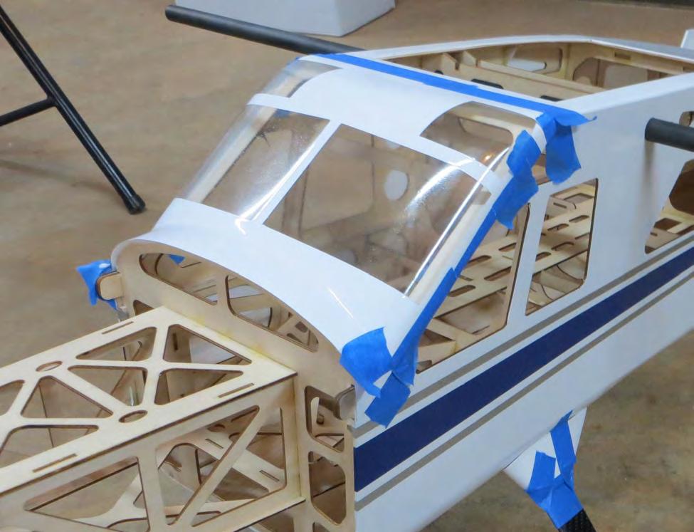
44 the cables so that there is no slack but do not make them guitar string tight as doing so can overstress the servo. Windscreen Installation 51. Next we'll install the windscreen. You have the choice of gluing the windscreen into place with a specialty glue like Pacer Formula

45 canopy glue or sewing it on with screws (not included). Also, a pair of Lexan car body scissors will make this step much easier! 52. Locate the windscreen. Crudely trim it so that you can place it into position. 53. Use blue tape to mark a cut line with the tape being placed inside the line where you will trim the canopy. This will help to prevent the canopy edges from splitting while being cut. 54. Test fit and trim as needed. Attach canopy with a thick bead of canopy glue and tape in place with painters tape and allow to dry overnight. Alternately you could sew the canopy in place with multiple small screws. Photos of both attachment methods are shown. 45

46 46

47 Motor and Electronic Speed Control Installation 55. Locate the following and prepare the motor for mounting A. Motor (Torque 4016/500) B. ESC (Airboss 80A) C. Supplied Torque hardware kit with X mount and Bolt-on Prop Adapter D. 2.5mm Hex Driver E. 3mm Hex driver F. Small Phillips head screwdriver G. Thread lock 47


48 56. Secure the prop adapter to the motor with supplied socket head cap bolts using blue thread lock on each bolt. 48


49 57. Next slide the provided collar over the motor shaft and secure in place with the set screw. Place a small drop of thread lock on the threads of the set screw to prevent it from backing out. 58. Attach the Supplied X mount with the 4 Philips head screws. Again use a drop of thread lock on each screw. 49


50 59. Locate the 4mm black cap bolts and washers to attach the assembled motor to the firewall. 60. Using a drop of thread lock on each bolt attach the motor to the firewall. 50


51 61. Using a couple Zip ties and a scrap piece of foam mount the ESC to the bottom of the motor box. 62. Connect the wires of the ESC and the motor and secure them to the motor box with nylon cable ties. 63. Attach a 12 servo wire extension and a 8-10 battery extension to the ESC and route them into the fuselage. There are 51

52 2 locations in the fuselage for mounting external ESC and BEC switches. If you are going to use a switch go ahead and mount it now. 52

53 Mounting the Cowl 64. Locate the following: A. Cowl B. Exhaust stacks C. Contact adhesive or Epoxy D. Sandpaper E. Painters tape F. Drill bit G. Felt tip pen 53

54 65. Scuff the bottom of the exhaust stacks and the indentions on the cowl where they will mount. 54


55 66. Using contact adhesive or epoxy glue the exhaust stacks to the cowling and hold them in place with painter s tape until the glue is dry. 55


56 67. When the glue for the exhaust stacks is fully cured, tear 4 short pieces of painter s tape and place each piece of tape on the side of the fuselage so that each piece corresponds with one of the 4 cowl mounting tabs. Use a felt tipped pen to mark the location of the center of each mounting tab. 68. Slide the Cowl into position. Install the spinner onto the motor shaft for reference and once satisfied with the cowl position, roll the tape back into place and secure the cowl. Use a 1/16 drill bit to drill a hole at the location of the dot on each piece of tape. 56


57 69. Remove the tape and cowl and add a drop of CA to each hole. Mount the cowl with the 4 of the small wood screws included with the kit. 57

58 70. Use a sharp hobby knife or soldering iron to remove the covering over the air escape holes in the bottom of the fuselage. 71. Mount your receiver as shown and tidy up the servo extensions. Pictured mounted to the battery tray are 2 multiplug extensions to make plugging in your aileron/flap servo leads easier. Affix a strip of Velcro to the battery tray and retain your battery with a Velcro strap. 58


59 72. Install your prop and spinner. 59


60 73. Insert the carbon wing tube into the sleeve in the fuselage. Slide the wings into position taking care to insert the servo extensions into the fuselage. Secure the wings be inserting the nylon wing bolts into the holes in the fuselage and threading them into the blind nut in the wing root. 74. Attach the struts using the supplied 3mm cap head screws. You may find it easiest to start with the wing attachment first. 60
61 This concludes the assembly process for the Turbo Bushmaster. Preparing for flight! With the wing and struts attached, place your battery on the battery tray and pick up the Bushmaster by the wing tube. Shift the battery until the plane balances on the tube. This is a safe location to begin test flying. Adjust CG to your liking, then mark the tray to know where to position the battery each flight. Typically the plane balances with the battery centered on the tray just forward of the wing tube as shown in the photo for step number 71. It is recommend you first fly the model in standard configuration to get used to its flight characteristics before beginning to experiment with flaps. When deploying flaps you will need to add an elevator mix that compensates for the flaps and provides a few degrees of down elevator. A comprehensive and detailed setup document written by designer Cody Wojcik will cover various mixes to experiment with and will be posted on the Extreme Flight website. Thanks so much for your business and we hope you enjoy flying your Turbo Bushmaster as much as we have! 61
RYAN STA SAFETY PRECAUTIONS. "Sport Scale E-Power ARF" For Intermediate and Advanced Fliers. This radio control model is not a toy!
 RYAN STA "Sport Scale E-Power ARF" For Intermediate and Advanced Fliers. SAFETY PRECAUTIONS This radio control model is not a toy! First-time builders should seek advice from people with model building
LANDING GEAR. 1. Fit landing gear into slots on bottom of fuselage.
 LANDING GEAR 1. Fit landing gear into slots on bottom of fuselage. 4. Use channel-lock pliers to press blind nuts into position (note: drilled hole should be slightly smaller than shaft of blind nut for
Assembly Manual / Airframe 65 Vyper SAFETY in Assembly SAFETY in Flying
 1 Assembly Manual / Airframe 65 Vyper Thank you for purchasing this 3DHobbyShop ARF RC aircraft. If you have any issues, questions, concerns or problems during assembly, please contact our tech department
Super Sky Surfer 2000 Assembly Instructions
 Super Sky Surfer 2000 Assembly Instructions Note: Plug and Play version of the Sky Surfer comes with fuselage pre-glued and motor/servos installed. If you wish to route antennas or wires through the tail,
High performance 90mm fiberglass jet
 High performance 90mm fiberglass jet Assembly manual For intermediate and advanced fliers only! Specs Wingspan: 1255mm Fuselage length: 1250mm Flying weight: 2600-3000g Wing area: 22.6 dm² Wing loading:
Corvus Racer CC
 Corvus Racer 540 35CC Item No:L-G035008 Specifications Wing Span Length Wing Area Flying Weight Glow Gasoline Electric Radio mm mm 1200sq in (77.4sqdm) 9.9-12lbs(4.5-5.5kg) 91-1.20(2C) 1.10-1.40(4C) 20-40cc
Citabria Pro. Aerobatic Parkflyer. by Joel Dirnberger
 Citabria Pro Aerobatic Parkflyer by Joel Dirnberger Revision C: December 21, 2004 Citabria Pro Building Instructions Length: Wingspan: Wing Area: Flying Weight: Wing Loading: Functions: Specifications:
62 AJ Acuity Assembly Instructions
 62 AJ Acuity Assembly Instructions Congratulations The all-new AJ Aircraft Acuity was designed to give you all of the precision flight abilities of expensive composite aircraft, in a more traditional balsa
INCLUDED IN THIS KIT: SPECIFICATION: NEEDED BUILDING TOOLS: REQUIRED EQUIPMENT:
 Please review this entire manual before beginning assembly. By doing so it will help you better understand each step as you progress in the actual building of your kit, and you will do a better job in
TIGER MOTH 120 ASSEMBLY INSTRUCTIONS
 TIGER MOTH 120 ASSEMBLY INSTRUCTIONS SPECIFICATIONS Wing Span: Length: Radio: Flying Weight: 1920mm 1580mm 4 channel with 6 servos 4200g AILERON ASSEMBLY 1 Start by removing the servo cover from the bottom
EXTRA 330SC 60CC. Item No:H G Specifications cc gas DA50,DA60, DLE55, DLE60(twin), 3W55. Description
, 3W55. Description") EXTRA 330SC 60CC Item No:H G060011 Specifications Wing Span Length Wing Area Flying Weight Gasoline Radio Description Carbon Fibre : 92" (2347mm) 84 1/2 " (2060mm) 1526.8 sq in(98.5sq dm) 16 17lbs(7300
EXTRA 330SC 60CC Item No:H G060011 Specifications Wing Span Length Wing Area Flying Weight Gasoline Radio Description Carbon Fibre : 92" (2347mm) 84 1/2 " (2060mm) 1526.8 sq in(98.5sq dm) 16 17lbs(7300
Extra 330LT CC. 2 Colour schemes H-G120001A ORACOVER FERRARI RED # ORACOVER WITH # ORACOVER BLACK # ORACOVER SILVER #
 Extra 330LT 85-125CC Item No:A-G120001 Specs: WING SPAN: LENGTH: WING AREA: FLYING WEIGHT: ENGINE: RADIO: Description Covering Material Carbon Fibre: 111 (2833mm) 100" (2530mm) 2139sq in (138sq dm) 25.3-28lbs
Edge 540 V3 35CC. Scheme A. Item No:L G Specifications. Flying Weight
 Edge 540 V3 35CC Item No:L G035016 Specifications Wing Span Length Wing Area Flying Weight Glow Gasoline Electric Radio Description 76 (1930mm) 74 (1879mm) 1200sq in(77.4sqdm) 9.9 12lbs(4.5 5.5kg) 91 1.20(2C)
78" EXTRA 300 ARF. Instruction Manual. Copyright 2009 Extreme Flight RC
 78" EXTRA 300 ARF Instruction Manual Copyright 2009 Extreme Flight RC Please take a few moments to read this instruction manual before beginning assembly. We have outlined a fast, clear and easy method
43in EPP Acrocub Instruction Manual
 43in EPP Acrocub Instruction Manual Specifications Wingspan: 43.3in (1100mm) Length: 41.3in (1050mm) Flying Weight: Approx. 1.5lb (670g) Dear Customer, Congratulations on your purchase of 43in EPP Acrocub
Corvus Racer Colour schemes. AeroPlus RC Copyright 2013 All Rights Reserved
 Corvus Racer 540 59 Item No:A E050003 Specifications WING SPAN: 59"(1500mm) LENGTH: 54.1"(1374mm) WING AREA: 654sq.in.(42.2sq.dm.) FLYING WEIGHT: 4.6 5.3lbs(2000 2300g) Electric:Brushless outrunner 8Oz.
28in Super EVA Foam. F-22 Raptor Kit. Specifications. Wingspan: 27.5in (700mm) Length: 38.3in (975mm) Flying Weight: Approx. 1.
 Length: 38.3in (975mm) Flying Weight: Approx. 1.") 28in Super EVA Foam F-22 Raptor Kit Specifications Wingspan: 27.5in (700mm) Length: 38.3in (975mm) Flying Weight: Approx. 1.2lbs (530g) Dear Customer, Congratulations on your purchase of 28in F22 Raptor
28in Super EVA Foam F-22 Raptor Kit Specifications Wingspan: 27.5in (700mm) Length: 38.3in (975mm) Flying Weight: Approx. 1.2lbs (530g) Dear Customer, Congratulations on your purchase of 28in F22 Raptor
10 th Anniversary 51 AJ Slick 540 Assembly Instructions
 10 th Anniversary 51 AJ Slick 540 Assembly Instructions Up Your Game! Fly AJ Aircraft From all of us at AJ Aircraft, we thank you for your business. Our custom designs, combined with top grade materials,
MECOA EZ-4061 Trainer
 MECOA EZ-4061 Trainer EZ-4061 is a newly designed, Almost Ready to Fly kit. It is an extremely easy to control trainer with strong construction and excellent aerodynamic performance. This is a great choice
Sbach 1,2m 3D/aerobatic EPP model Building instructions
 Sbach 1,2m 3D/aerobatic EPP model Building instructions Please refer to the Diagram sheet Diagrams A, B Press 2 carbon strips (1x3x1000 mm) into the grooves in the sides of the fuselage central part (the
30% Edge 540T Almost Ready to Fly
 Lanier R/C 30% Edge 540T Almost Ready to Fly WARNING! THIS IS NOT A TOY! THIS IS NOT A BEGINNERS AIRPLANE This R/C kit and the model you will build from it is not a toy! It is capable of serious bodily
Instruction Manual book
 Instruction Manual book ITEM CODE BH53. SPECIFICATION Wingspan : 1,250mm 49.21 in. Length : 930mm 36.61in. Weight : 1.1kg 2.42 Lbs. Parts listing required (not included). Battery: 3 CELLS-LI-POLY-11.1V-2,500
(Build Instructions)
") (Build Instructions) Specifications * Wingspan: 58cm * Length: 50cm * Flying Weight: 59 grams * Channels: 3 (Rudder Elevator Throttle) * Suggested Receiver: 4Ch Micro * Motor: 8mm GearDrive * Prop: GWS
(Build Instructions) Specifications * Wingspan: 58cm * Length: 50cm * Flying Weight: 59 grams * Channels: 3 (Rudder Elevator Throttle) * Suggested Receiver: 4Ch Micro * Motor: 8mm GearDrive * Prop: GWS
56 & 60 AJ Laser 230z Assembly Instructions
 56 & 60 AJ Laser 230z Assembly Instructions Congratulations Whether you're looking to go out and go 3d huckin' or lay down a smooth-as-butter precision flight, the 56 or 60 Laser 230z is for you! The wings
TWEETY 25 INSTRUCTION MANUAL. Almost Ready to Fly Nitro/Electric Aerobat FEATURES SPECIFICATIONS
 TWEETY 25 Almost Ready to Fly Nitro/Electric Aerobat INSTRUCTION MANUAL SPECIFICATIONS FEATURES WINGSPAN: 45.7 (1160mm) LENGTH: 38.6 (980mm) WING AREA: 370 sq in(24 sq dm) FLYING WEIGHT: Approx. 3.3 lbs
Focke-Wulf. FW-190a. Copyright 2016 Extreme Flight RC
 Focke-Wulf FW-190a Copyright 2016 Extreme Flight RC 1 Congratulations on your purchase of the AcesHigh Focke-Wulf 190A! The FW-190 was a backbone of the German Luftwaffe, BMW 801 twin-row radial powered,
F3A -70E ASSEMBLY MANUAL
 F3A -70E ASSEMBLY MANUAL The new F3A-70E, was designed in an extremely lightweight structure, the all wood airframe, and the new revolutionary Lift Generator on landing gear give the F3A-70E an impressive
Thunder Tiger Ace Hobby Page 1 6/8/10
 TOC 35% Katana Assembly Manual Thunder Tiger Ace Hobby Page 1 6/8/10 Table of contents Thunder Tiger Contact Information Page 3 Introduction.Page 4 Kit Contents.Page 5 Items Needed to Complete...Page 6
25mm EPP SU31. Instruction Manual. Specifications
 25mm EPP SU31 Instruction Manual Specifications Wingspan: 39.4in (1000mm) Length: 42in (1070mm) Wing Area: 448sq in (28.9sq dm) Flying Weight: Approx. 1.5lb (650-710g) Dear Customer, www.valuehobby.com/su31-epp.html
3DHobbyShop.com Edge Assembly Manual
 3DHobbyShop.com Edge 540 92 Assembly Manual Thank you for purchasing this 3DHobbyShop ARF RC aircraft. If you have any issues, questions, concerns or problems during assembly, please contact our tech department
INCLUDED IN THIS KIT: SPECIFICATION: NEEDED BUILDING TOOLS: REQUIRED EQUIPMENT:
 Please review this entire manual before beginning assembly. By doing so it will help you better understand each step as you progress in the actual building of your kit, and you will do a better job in
This pictorial document contains assembly recommendations including some fit and finish details that will be helpful when building this airplane
 This pictorial document contains assembly recommendations including some fit and finish details that will be helpful when building this airplane Problems found with this kit and a flight performance review
Hot Stik ARF WARNING. Copyright 2005 Carl Goldberg Products LTD CARL GOLDBERG PRODUCTS, LTD.
 Hot Stik ARF INSTRUCTIONS WARNING A radio-controlled model is not a toy and is not intended for persons under 16 years old. Keep this kit out of the reach of younger children, as it contains parts that
FUSELAGE CONSTRUCTION
 FUSELAGE CONSTRUCTION Note: prior to building and gluing on the work surface use protective covering on your building surface. (wax paper or clear wrap) Fit the laser cut Fuselage Front and Fuselage Rear
MXS R 30CC. Item No:L G Specifications. 67 1/2"(1720mm) (2C) (4C) 26 35cc gas DLE 30/35RA MLD35 JC30Evo.
 (2C) (4C) 26 35cc gas DLE 30/35RA MLD35 JC30Evo.") MXS R 30CC Item No:L G030008 Specifications Wing Span Length Wing Area Flying Weight Glow Gasoline Electric Radio Description Covering Material Carbon Fibre : 75"(1915mm) 67 1/2"(1720mm) 1023sq in(66sq
MXS R 30CC Item No:L G030008 Specifications Wing Span Length Wing Area Flying Weight Glow Gasoline Electric Radio Description Covering Material Carbon Fibre : 75"(1915mm) 67 1/2"(1720mm) 1023sq in(66sq
94 Yak 54 ARF WARNING
 94 Yak 54 ARF WARNING A radio-controlled model is not a toy and is not intended for persons under 16 years old. Keep this kit out of the reach of younger children, as it contains parts that could be dangerous.
Instruction Manual. Specification:
 Instruction Manual H I G Specification: Wingspan: 133 cm (52.3 inches) Length : 104 cm (40.9 inches) Weight : 1830gr Engine : 25-32 two stroke Radio : 4 channel - 4 servo H W I N G KIT CONTENTS: We have
C-180 Builder s Manual
 C-180 Builder s Manual. May 20, 2002 Last revised July 11, 2002 Copyright! 2002 Douglas Binder, Mountain Models www.mountainmodels.com sales@mountainmodels.com (719) 630-3186 1 Required Equipment! Xacto
FLITZEBOGEN-2 Assembly instructions
 FLITZEBOGEN-2 Assembly instructions Trim the end of the fuselage to the length of 925mm from the nose. Be careful to avoid splitting the carbon fibers. Sand the base of the stab mount in preparation for
87 Extra 330 ARF WARNING
 87 Extra 330 ARF WARNING A radio-controlled model is not a toy and is not intended for persons under 16 years old. Keep this kit out of the reach of younger children, as it contains parts that could be
BOOMERANG TORUS. Aerobatic Sport Jet for 20 to 34 lbs (P80 to P160) thrust turbines.
 thrust turbines.") BOOMERANG TORUS Aerobatic Sport Jet for 20 to 3 lbs (P80 to P160) thrust turbines. Specifications: Span... 83" (2209mm.) Span with Wingtip Tanks 90" (2286mm.) Length...87" (2108mm.) Weight 29 Lbs.(13.15
BOOMERANG TORUS Aerobatic Sport Jet for 20 to 3 lbs (P80 to P160) thrust turbines. Specifications: Span... 83" (2209mm.) Span with Wingtip Tanks 90" (2286mm.) Length...87" (2108mm.) Weight 29 Lbs.(13.15
105" TIGER MOTH ARF INSTRUCTION MANUAL VERSION 1.0
 105" TIGER MOTH ARF INSTRUCTION MANUAL VERSION 1.0 Step 1. Installation of the aileron servos 1) Mount aileron servo to servo mounting blocks with servo s screws. Install servo mounting plate with screws.
F-16 Falcon 70mm EDF
 F-16 Falcon 70mm EDF Instruction manual Specifications: Winspan: 640 mm Length: 990 mm Weight: 900-1100 gram Ducted fans 70mm x 1 Required tools and components:. 4 ch. Computer Radio system w/ 2 servos.
Revolution 3D-mini ARF
 Revolution 3D-mini ARF 1 Included Hardware 4 Dubro Micro Control Horns #DUB848 2.32 x 18" Linkage Wire (Music Wire) 1 1.5 x 1.25 x 1/8 Balsa Ply (for motor mount) 1 5" piece of Velcro (Optional recommended,
Instruction Manual. Item No: AL001
 Instruction Manual Item No: AL001 Specifications: Wingspan: 2037mm (80.2 in) Length: 1677mm (66 in) Wing Area: 65.5dm2 (1015.3 sq in) Flying Weight: 7.6kg (16.7 lbs) Engine(not incl.): 45-50cc Gas Radio(not
Parts Identification
 We are excited to introduce the Model Aero Aqua Sport. This is an excellent sport flyer, equally at home flying from grass fields, water, or even snow! The unique V-tail gives the Aqua Sport a distinctive
HIGH-END TECHNOLOGY. Electric ducted fan Starfighter
 HIGH-END TECHNOLOGY RC Electric ducted fan Starfighter First we want to thank and congratulate you with your decision in buying one of our Kits. The Starfighter puts together very easily so there is not
Stream NXT - assembly instructions
 Stream NXT - assembly instructions Recommended settings CG (measured from root leading edge): Speed/launch camber (+down, near the wing root): Cruise camber (+down, near the wing root): Thermal camber
Millennium RC presents The New and Improved (now even easier to build and cover!) SSX X-Trainer Build Kit
 SSX X-Trainer Build Kit") Millennium RC presents The New and Improved (now even easier to build and cover!) SSX X-Trainer Build Kit Wing span: Approx. 42 Wing Area: 504 sq. in. Wing Loading: 6.71 oz/ sq. ft. Introduction: The Slow
Millennium RC presents The New and Improved (now even easier to build and cover!) SSX X-Trainer Build Kit Wing span: Approx. 42 Wing Area: 504 sq. in. Wing Loading: 6.71 oz/ sq. ft. Introduction: The Slow
I hope you enjoy the Spirit as much as I have. Scott DeTray Model Aero
 We are excited to introduce the Model Aero Spirit. Inspired by the magnificent Northrop Grumman B-2 Spirit Stealth Bomber, the Spirit is a great flyer, on land or water. It tracks like an arrow and is
WE GET PEOPLE FLYING AT-6
 TM WE GET PEOPLE FLYING AT-6 Texan.60 ARF ASSEMBLY MANUAL Specifications Wingspan:... 67.5 in (1714mm) Length:... 48 in (1219mm) Wing Area:... 706 sq in (45.54 sq dm) Weight:... 7 8.5 lb (3.17 3.85 kg)
Assembly Instructions. Stinger 120. Almost Ready to Fly
 Stinger 120 Almost Ready to Fly Important Information: Please inspect the plane before beginning to assemble to make sure you are happy with it. After assembly has begun you cannot return the kit. If you
Assembly Manual / Airframe 70 Velox
 Assembly Manual / Airframe 70 Velox Thank you for purchasing this 3DHobbyShop ARF RC aircraft. If you have any issues, questions, concerns or problems during assembly, please contact our tech department
CARL GOLDBERG PRODUCTS, LTD.
 Eagle 400 WARNING A radio-controlled model is not a toy and is not intended for persons under 16 years old. Keep this kit out of the reach of younger children, as it contains parts that could be dangerous.
67 Edge 540 ARF WARNING
 67 Edge 540 ARF INSTRUCTIONS WARNING A radio-controlled model is not a toy and is not intended for persons under 16 years old. Keep this kit out of the reach of younger children, as it contains parts that
SebArt professional line
 SebArt professional line Wind S 110 ARF ASSEMBLY MANUAL The new Wind S 110 ARF was designed by Italy aerobatic pilot, Sebastiano Silvestri. This professional ARTF kit is the result of Sebastiano s 20 years
Assembly Instructions
 Congratulations AJ Aircra thanks you for the purchase of this airplane. Top grade materials and precision assembly has gone into this to make this a top quality aircra. Following the direcons closely,
Ryan STA Sport Scale Model Aircraft Assembly and Instruction Manual
 Ryan STA Sport Scale Model Aircraft Assembly and Instruction Manual Warning: This radio controlled model is not a toy. It requires skill to fly and is not recommended for the novice pilot. It should not
Zeon PDF Driver Trial
 Mach Dart Slope Soarer Congratulations on your purchase of the Mach Dart Glider. This aircraft was crafted utilizing the latest technology in composite model aircraft design and manufacture. The Dart is
Thank you for your purchase of the Lee Ulinger, FoamtanaS, Yak-55, or Extra 330 3D Depron foam, Aerobatic airplane.
 Thank you for your purchase of the Lee Ulinger, FoamtanaS, Yak-55, or Extra 330 3D Depron foam, Aerobatic airplane. Tools you will need to build Recommended additional items: #11 hobby knife Motor: Hacker
ULS Cherokee. Ultra Low Speed aircraft for indoor RC flying. Zippkits. Specifications: Required to complete:
 Zippkits ULS Cherokee Ultra Low Speed aircraft for indoor RC flying. Specifications: Span- 28 inches Wing Area- 151 Sq/In Wing Loading- 3.0 ounces/ft Weight- 3.5 ounces RTF Build time- 1-2 Hours Radio-
Instructions - Stobel V2
 Instructions - Stobel V2 Congratulations on the purchase of your Stobel, a high end DLG-competition model from LE-composites. We hope you will be happy and successful. To ensure the optimum build we ask
Aviator Trainer40 ARF Instruction Manual Specifications
 Aviator Trainer40 ARF Instruction Manual Specifications Wingspan: 65.0 in (1650 mm) Length: 53.1 in (1350 mm) Wing Area: 729sq in (47.0 sq dm) Flying Weight: 5.3 lbs (2400g) Dear Customer, Congratulations
E-AERO EPP PITTS KIT From BP HOBBIES. Parts Included in kit
 E-AERO EPP PITTS KIT From BP HOBBIES Parts Included in kit Thank you for purchasing the BP Hobbies/E-aero EPP Pitts. Please take the time to read through the instruction manual before beginning the build.
Switchback Sport Builder s Manual
 Switchback Sport Builder s Manual Thank you for purchasing the Switchback Sport. The Switchback Sport has been designed for the novice to intermediate pilot who wants a plane with good performance that
INSTRUCTION MANUAL BOOK.
 INSTRUCTION MANUAL BOOK. SPECIFICATION Wingspan : 164 cm 64.57in. Length : 135 cm 53.15 in. Weight : 3.3kg 7.26 lbs. Servo : 7 servos. Radio : 4 channels. Engine : 61 cu.in-2 stroke. 91 cu.in-4 stroke.
HIGH-END TECHNOLOGY. Electric ducted fan rafale
 HIGH-END TECHNOLOGY RC Electric ducted fan rafale First we want to thank and congratulate you with your decision in buying one of our Kits. The Rafale puts together very easily so there is not much explanation
77 Edge 540 ARF WARNING
 77 Edge 540 ARF INSTRUCTIONS WARNING A radio-controlled model is not a toy and is not intended for persons under 16 years old. Keep this kit out of the reach of younger children, as it contains parts that
Instruction Manual book
 Instruction Manual book ITEM CODE: BH50. SPECIFICATION Wingspan : 1,600 mm 62.99 in. Length : 1,230 mm 48.43 in. Weight : 2.5 kg 5.5 Lbs. Radio : 06 channels. Servo : 07 servos. Electric Motor : ( 02pcs
Eva. Extremely Versatile Airframe
 Eva Extremely Versatile Airframe Eva Specifications Length: 32 Weight (without battery): ~12oz. Revision History Date Revision Notes/Comments 6/3/05 Document initial creation. Thank you for purchasing
Stearman PT-17 KIT WARRANTY
 Stearman PT-17 KIT # K-306 Assembly Instructions Version 2 02-17-16 Designed by Tom Herr WARRANTY Sig Manufacturing Co, Inc. guarantees this kit to be free from defects in both material and workmanship
CARL GOLDBERG PRODUCTS, LTD.
 Chipmunk 400 WARNING A radio-controlled model is not a toy and is not intended for persons under 16 years old. Keep this kit out of the reach of younger children, as it contains parts that could be dangerous.
JAMISON SPECIAL. Building Guide
 JAMISON SPECIAL Building Guide WING Mark then drill holes for wing jig rods. Slide Ribs onto jig rods Mark the rib positions on 1/16 x 1 trailing edge, 1/4 x 1/4 leading edge & 1/4 x 1/4 spars Pin ribs
Specifications Wingspan: 43cm Flying Weight: 33 grams (with battery) Channels: 3 Suggested Receiver: 4Ch Micro Motor: 7mm Brushed Geardrive
 Channels: 3 Suggested Receiver: 4Ch Micro Motor: 7mm Brushed Geardrive") Specifications Wingspan: 43cm Flying Weight: 33 grams (with battery) Channels: 3 Suggested Receiver: 4Ch Micro Motor: 7mm Brushed Geardrive Airframe Kit (Included Contents) * Airframe Parts Sheets (Depron)
Specifications Wingspan: 43cm Flying Weight: 33 grams (with battery) Channels: 3 Suggested Receiver: 4Ch Micro Motor: 7mm Brushed Geardrive Airframe Kit (Included Contents) * Airframe Parts Sheets (Depron)
ALBATROSS by CRASHTESTHOBBY.COM
 ALBATROSS by CRASHTESTHOBBY.COM The Albatross is a unique slow flyer designed to put its nose on the horizon and level its own wings without a pilot. It is very quiet and designed to use inexpensive electronics.
Super Cub 25e ARF. Assembly Manual
 Super Cub 25e ARF Assembly Manual Notice All instructions, warranties and other collateral documents are subject to change at the sole discretion of Horizon Hobby, Inc. For up-to-date product literature,
THE APOGEE A 100-INCH AMA DURATION SAILPLANE FROM DYNAFLITE
 THE APOGEE A 100-INCH AMA DURATION SAILPLANE FROM DYNAFLITE Apogee is the intermediate sailplane designed to be competitive in AMA duration contests. Effective spoilers, rudder and full flying stabilizer
SwitchBack Senior. SwitchBack Senior Specifications
 SwitchBack Senior SwitchBack Senior Specifications Wingspan: 55.4 in. Length: 41 in. Wing Area: 597 sq. in. Weight (Ready to Fly): 34 to 37 oz. Wing Loading: 8.2 to 8.9 oz. / sq. ft. Version 1.05, March
FUJI FA-200 AERO SUBARU
 FUJI FA-200 AERO SUBARU SEMI SCALE SPORT MODEL AERO SUBARU Assembly and Operations Manual Please review this manual throughly Before assembling or Operating The AERO SUBARU Semi scale sport model We ve
S.E.5a (Build Instructions)
") S.E.5a (Build Instructions) Specifications Wingspan: 38 cm Length: 31cm Flying Weight: 41 Channels: 3 (Rudder Elevator Throttle) Suggested Receiver: 3Ch Brick Motor: 7mm Geared Motor Airframe Only Kit
S.E.5a (Build Instructions) Specifications Wingspan: 38 cm Length: 31cm Flying Weight: 41 Channels: 3 (Rudder Elevator Throttle) Suggested Receiver: 3Ch Brick Motor: 7mm Geared Motor Airframe Only Kit
LANIER - Double Trouble - INSTRUCTIONS. Tail 1 T1 ¼ Balsa 1 T2 ¼ Balsa 2 T3 ¼ Balsa 1 T4 ¼ Balsa 1 T5 ¼ Balsa 1 T6 ¼ Balsa 2 J1 ¼ Balsa 2 J2 Lite ply
 Tail 1 T1 ¼ Balsa 1 T2 ¼ Balsa 2 T3 ¼ Balsa 1 T4 ¼ Balsa 1 T5 ¼ Balsa 1 T6 ¼ Balsa 2 J1 ¼ Balsa 2 J2 Lite ply Other Parts 2 Aluminum Gear 1 3/32 Music wire tail skid 2 Elevator and J-plane joiner wire
Bashing The Hanger 9 Cessna 182 ARF Part 4
 Bashing The Hanger 9 Cessna 182 ARF Part 4 Eric Helms Pongo Air This is the final installment of a four-part article covering a variety of modifications incorporated into a Hanger 9 Cessna 182 ARF. Upgrades
Assembly Instructions STINGER
 STINGER 120 ARF Important Information: Please inspect the plane before beginning to assemble to make sure you are happy with it. After assembly has begun you cannot return the kit. If you find a problem
FOKKER D.VII 1:7.4. No.EP-46K. MTH HOBBY PRODUCTS INDUSTRIAL CO., LTD. MTH HOBBY 2015
 No.EP-46K FOKKER D.VII 1:7.4 MTH HOBBY PRODUCTS INDUSTRIAL CO., LTD. www.mth.com.tw mthhobby@mth.com.tw MTH HOBBY 2015 SPECIFICATION: Wing span: 1200mm Wing area: 41 dm Length: 990mm Weight: 1400g, including
34" PELICAN by CRASH TEST HOBBY
 34" PELICAN by CRASH TEST HOBBY The Pelican is a 34" trainer that can level its own wings and put its nose on the horizon once trimmed and balanced. It can handle more wind than most EZ flying planes in
Hand-made Almost Ready to Fly R/C Model Aircraft ASSEMBLY MANUAL
 Hand-made Almost Ready to Fly R/C Model Aircraft ASSEMBLY MANUAL Specifications Wingspan -----------------------.148 cm--------------- 58.3 in. Wing area ----------------------- 3474sq. cm ---- 538.4sq
EPP Rebel Z 35. White Red w/ Blue Orange w/ Blue Orange w/burgundy Other. Specs. Color - Bottom White Black Checkers Silver Checkers Other Checkers
 EPP Rebel Z 35 Specs AUW ~10.0oz Width 35.28 Length 34.67 Wing Area 1.44 sqft Horz Area 2.35 sqft Vert Area.91 sqft
Sig Mfg. Co., Inc South Front Street...Montezuma, Iowa 50171
 Sig Mfg. Co., Inc...401-7 South Front Street...Montezuma, Iowa 50171 Introduction The SEALANE takes off and lands on water just as easy as the Sig Kadet LT40 does on solid ground. Gentle, graceful, sure
TIGER SHARK-40 ARF ASSEMBLY MANUAL
 TIGER SHARK-40 ARF ASSEMBLY MANUAL Kangke Industrial USA, Inc. 65 East Jefryn Blvd. Deer Park NY 11729 http://www.kangkeusa.com E-mail: info@kangkeusa.com Tel: 1-877-203-2377 Fax: 1-631-274-3296 Congratulations!
AT channel 6 servos
 Wing Span: Wing Area: Fuselage Length: Flying weight: Power system: Radio: 60.7in/1540mm 561 sq in/36.3 sq dm 44.1in/1120mm 6.9 Ibs/ 3100g 46(2C0/71(4C) 5 channel 6 servos AT6-46 INSTALLING AILERONS Begin
P-39 Airacobra INSTRUCTION MANUAL SAFETY PRECAUTIONS. Specification: 30cc gasoline engine. This R/C airplane is not a toy!
 P-39 Airacobra Specification: Length: Wing span: Wing area: Wing loading: Flying weight: Radio: Engine: 7mm(70. ) 00mm(0.3 ) 7.5sq.dm(.5sq.ft) 93g/sq.dm(30.5oz/sq.ft) 7.3kg(.bs) ch & servos 30cc gasoline
ParkJet Builder s Manual
 ParkJet Builder s Manual Thank you for purchasing the ParkJet. The ParkJet is a profile ducted fan airplane that can be flown in a larger park. The ParkJet was initially designed by Scott Stoops and modified
MEMO. Assembly Manual. Warranty. Notice: Adult Supervision Required. No.3841
 MEMO Assembly Manual No.3841 Specifications: Fuselage Length 54.6 (1387mm) Fuselage Width 15.7 (400mm) Fuselage Height 17.8 (452mm) Full Equipped Weight 8.5lbs (3860g) Warranty This kit is guaranteed to
32 Crack Yak-55. Twisted Hobbys Specifications. Rev: v004a 1
 32 Crack Yak-55 By RC Factory Specifications Wing span 32 / Length 31 AUW 160-175g (with Landing Gear) 50-70w outrunner motor (19g 24g) 6-12 amp ESC / 2s 360 450mAh battery 4 ch radio / 2x 4g servos /
Warbird Series Zero - 32 Assembly Manual
 Warbird Series Zero - 32 Assembly Manual Specifications Wing Span: 32 inches Wing Area: 210 in 2 Fuselage Length: 26 inches Weight (ready to fly): 11 to 13 oz. Wing Loading: 7.5 to 8.9 oz/ft 2 Designed
PITTS S2S CONSTRUCTION
 PITTS S2S CONSTRUCTION FUSELAGE CONSTRUCTION 1) Place the right fuselage side over the plan and mark the former positions. Place the left side over the right side and mark the former positions. Glue F1
F - 4u Corsair (50cc)
") F - u Corsair (50cc) Specification: Length: 73(.3") Wing span: 0mm(5") Wing area: 7.00sq.dm(9.39sq.ft) Wing loading: 35.g/sq.dm(.5oz/sq.ft) Flying weight:.kg(.0lbs) Radio: ch & 0servos Engine: 50cc gasoline
F - u Corsair (50cc) Specification: Length: 73(.3") Wing span: 0mm(5") Wing area: 7.00sq.dm(9.39sq.ft) Wing loading: 35.g/sq.dm(.5oz/sq.ft) Flying weight:.kg(.0lbs) Radio: ch & 0servos Engine: 50cc gasoline
RESolution V2 Manual
 RESolution V2 Manual Note for the German Manual: Yellow Bottle thick CA Pink Bottle Med CA Blue tube 5 minute Epoxy Green tube 90 Minute Epoxy Construction of the Fuselage Step 1: Cover the plan with a
Aichi D3A1 INSTRUCTION MANUAL SAFETY PRECAUTIONS. Specification:
 Aichi D3A Specification: Length: 50mm(0. ) Wing span: 057mm( ) Wing area: 7.sq.dm(.sq.ft) Wing loading: 99.9g/sq.dm(3.oz/sq.ft) Flying weight: 7.kg(.7lbs) Radio: ch & 7servos Engine: 0 -cycle C.G: 35mm
STEP 1 STEP 2 STEP 3. Page 2
 INSTRUCTION MANUAL Congratulations on your purchase of the Bullet ARTF - the first Almost Ready to Fly version of this classic lowwinger. Based on the original and timeless Bullet design, the new Ripmax