An Oscillator is a circuit which produces a periodic waveform at its output with only the dc supply voltage at the input. The output voltage can be
|
|
|
- Denis Stevenson
- 5 years ago
- Views:
Transcription
1
2 An Oscillator is a circuit which produces a periodic waveform at its output with only the dc supply voltage at the input. The output voltage can be either sinusoidal or non sinusoidal depending upon the type of oscillator. Two major classifications of oscillators are Feedback and Relaxation oscillators.

3

4 Feedback Amplifier consists of an amplifier for gain and a feedback circuit for attenuation and phase shift.
5 Relaxation oscillator uses an RC timing circuit and a device that changes states to generate a periodic waveform A Triangular Wave Oscillator
6 Conditions for Oscillation Phase shift around the feedback loop must effectively be 0 degree. Loop gain must equal unity.
7
8 Start up Conditions Unity gain condition must be maintain to obtain sustained oscillations. Loop gain in the beginning must be greater than unity to acquire the desired level of oscillation. Once the desired level is achieved, the gain should reduce to unity for sustained oscillations. This reduction in gain is achieved by automatic gain control circuits (AGC). Initial voltage for positive feedback is provided by thermal noise produced in resistors or from other components or from power supply turn on transients.
9 Feedback circuit permits only that frequency which equals the resonant frequency to appear in phase at the input.
10 Oscillators with RC Feedback RC Feedback Oscillators are generally used for frequencies up to 1 MHz. Wien-Bridge, Phase-Shift and Twin-T Oscillators are the examples Wien-Bridge is the most commonly used one among these
11 The Wien-Bridge Oscillator
12 Fundamental part of Wien-Bridge Oscillator is Lead-Lag circuit. R 1 and C 1 together form the lag circuit. R 2 and C 2 form the lead circuit. At low frequencies, the lead circuit dominates due to the high reactance of C 2 As the frequency increases,xc 2 decreases,thus allowing the output voltage to increase. At some specified frequency, the lag circuit takes over, and the decreasing value of Xc 1 causes the output voltage to decrease.

13 RC Lag Circuit An RC lag circuit is a phase shift circuit in which the output voltage lags the input voltage by a specified amount OR

14 RC Lead Circuit An RC lead circuit is a phase shift circuit in which the output voltage leads the input voltage by a specified amount
15 At the resonant frequency If R 1 =R 2 and Xc 1 =Xc 2 then Below f r, the lead circuit dominates and output leads the input Above f r, the lag circuit dominates and output lags the input Lead Lag circuit is used in the positive feedback loop of an op amp


16 The two conditions for sustained oscillation are met as shown on the next slide
17 To achieve a closed loop gain of 3
18 Start up Condition

19 Achieving Sustained Oscillation Initially zener diode appear as open when dc supply is first applied R3 now comes in series with R1,increasing the closed loop gain as When the output signal level reaches the zener breakdown voltage, zeners start conducting while shorting R3 and hence reducing the closed loop gain to 3. Loop gain is now unity and oscillations are thus sustained

20 This circuit is not very efficient since it suffers from nonlinearities present in zener diodes It is difficult to achieve undistorted sinusoidal output using the above circuit. Another method of AGC uses JFET in the negative feedback loop as a voltage controlled resistor.
21 This method can produce an excellent sinusoidal waveform that is stable A JFET operating with a small or zero V DS operates in the ohmic region As the gate voltage increases, the drain to source resistance increases This change in resistance is used for automatic gain control (AGC) With no output signal, gate is at zero potential and rds is minimum and loop gain is greater than 1 Negative excursions of the output forward bias the diode causing the capacitor C 3 to charge to a negative voltage This increases the source to drain resistance and reduces the gain and hence the output. Try Example 16.1 of Floyd

22 The Phase Shift Oscillator Each of the three RC circuits in the feedback loop can provide a maximum of 90 degree phase shift, but each is designed to provide 60 degree phase shift Total phase shift provided by the three RC circuits is thus 180 degree. Another 180 degree is provided by the inversion of the op amp; hence making it 360 degree(0 degree) in total around the loop.
23 A series RC circuit shifts the phase of the output voltage by an amount that depends upon the values of R and C and the frequency of the signal. Generally the requirement is to provide a phase shift of 180 degrees in the feedback path A single RC lag circuit is limited to phase shifts that are smaller than 90 degree
24 The attenuation provided by the three section RC feedback circuit is B=1/29 Where B=R 3 /R f (Derivation given in Appendix-B, Equation 16-3) When
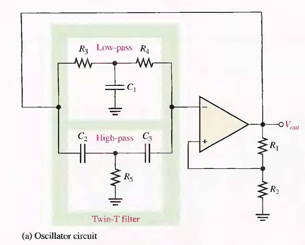
25 Twin-T Oscillator Two T-type RC filters used in the feedback loop One has the low pass response and the other has the high pass response The combined parallel filters produce a band stop or notch response with a center frequency equal to f r
26
27 Oscillation cannot occur at frequencies above or below f r because of the negative feedback through the filters At f r,negative feedback is negligible and the positive feedback provides oscillation The Band Stop circuit can also be implemented as shown on the next slide


28 At the resonant frequency, the impedance is maximum
Lecture # 11 Oscillators (RC Circuits)
") December 2014 Benha University Faculty of Engineering at Shoubra ECE-312 Electronic Circuits (A) Lecture # 11 Oscillators (RC Circuits) Instructor: Dr. Ahmad El-Banna Agenda Introduction Feedback Oscillators
December 2014 Benha University Faculty of Engineering at Shoubra ECE-312 Electronic Circuits (A) Lecture # 11 Oscillators (RC Circuits) Instructor: Dr. Ahmad El-Banna Agenda Introduction Feedback Oscillators
Oscillator Principles
 Oscillators Introduction Oscillators are circuits that generates a repetitive waveform of fixed amplitude and frequency without any external input signal. The function of an oscillator is to generate alternating
EMT212 Analog Electronic II. Chapter 4. Oscillator
 EMT Analog Electronic II Chapter 4 Oscillator Objectives Describe the basic concept of an oscillator Discuss the basic principles of operation of an oscillator Analyze the operation of RC, LC and crystal
EE301 ELECTRONIC CIRCUITS CHAPTER 2 : OSCILLATORS. Lecturer : Engr. Muhammad Muizz Bin Mohd Nawawi
 EE301 ELECTRONIC CIRCUITS CHAPTER 2 : OSCILLATORS Lecturer : Engr. Muhammad Muizz Bin Mohd Nawawi 2.1 INTRODUCTION An electronic circuit which is designed to generate a periodic waveform continuously at
BENE 2163 ELECTRONIC SYSTEMS
 UNIVERSITI TEKNIKAL MALAYSIA MELAKA FAKULTI KEJURUTERAAN ELEKTRONIK DAN KEJURUTERAAN KOMPUTER BENE 263 ELECTRONIC SYSTEMS LAB SESSION 3 WEIN BRIDGE OSCILLATOR Revised: February 20 Lab 3 Wien Bridge Oscillator
Expect to be successful, expect to be liked,
 Thought of the Day Expect to be successful, expect to be liked, expect to be popular everywhere you go. Oscillators 1 Oscillators D.C. Kulshreshtha Oscillators 2 Need of an Oscillator An oscillator circuit
OBJECTIVE TYPE QUESTIONS
 OBJECTIVE TYPE QUESTIONS Q.1 The breakdown mechanism in a lightly doped p-n junction under reverse biased condition is called (A) avalanche breakdown. (B) zener breakdown. (C) breakdown by tunnelling.
Lecture 28 RC Phase Shift Oscillator using Op-amp
 Integrated Circuits, MOSFETs, OP-Amps and their Applications Prof. Hardik J Pandya Department of Electronic Systems Engineering Indian Institute of Science, Bangalore Lecture 28 RC Phase Shift Oscillator
Philadelphia University Faculty of Engineering Communication and Electronics Engineering. Amplifier Circuits-IV
 Module: Electronics II Module Number: 6503 Philadelphia University Faculty o Engineering Communication and Electronics Engineering Ampliier Circuits-IV Oscillators and Linear Digital IC's: Oscillators:
21/10/58. M2-3 Signal Generators. Bill Hewlett and Dave Packard s 1 st product (1939) US patent No HP 200A s schematic
 US patent No HP 200A s schematic") M2-3 Signal Generators Bill Hewlett and Dave Packard s 1 st product (1939) US patent No.2267782 1 HP 200A s schematic 2 1 The basic structure of a sinusoidal oscillator. A positive feedback loop is formed
M2-3 Signal Generators Bill Hewlett and Dave Packard s 1 st product (1939) US patent No.2267782 1 HP 200A s schematic 2 1 The basic structure of a sinusoidal oscillator. A positive feedback loop is formed
Chapter.8: Oscillators
 Chapter.8: Oscillators Objectives: To understand The basic operation of an Oscillator the working of low frequency oscillators RC phase shift oscillator Wien bridge Oscillator the working of tuned oscillator
OSCILLATORS AND WAVEFORM-SHAPING CIRCUITS
 OSILLATORS AND WAVEFORM-SHAPING IRUITS Signals having prescribed standard waveforms (e.g., sinusoidal, square, triangle, pulse, etc). To generate sinusoidal waveforms: o Positive feedback loop with non-linear
11. Chapter: Amplitude stabilization of the harmonic oscillator
 Punčochář, Mohylová: TELO, Chapter 10 1 11. Chapter: Amplitude stabilization of the harmonic oscillator Time of study: 3 hours Goals: the student should be able to define basic principles of oscillator
Oscillators. An oscillator may be described as a source of alternating voltage. It is different than amplifier.
 Oscillators An oscillator may be described as a source of alternating voltage. It is different than amplifier. An amplifier delivers an output signal whose waveform corresponds to the input signal but
UNIVERSITI MALAYSIA PERLIS
 UNIVERSITI MALAYSIA PERLIS ANALOG ELECTRONICS II EMT 212 2009/2010 EXPERIMENT # 3 OP-AMP (OSCILLATORS) 1 1. OBJECTIVE: 1.1 To demonstrate the Wien bridge oscillator 1.2 To demonstrate the RC phase-shift
The steeper the phase shift as a function of frequency φ(ω) the more stable the frequency of oscillation
 the more stable the frequency of oscillation") It should be noted that the frequency of oscillation ω o is determined by the phase characteristics of the feedback loop. the loop oscillates at the frequency for which the phase is zero The steeper the
It should be noted that the frequency of oscillation ω o is determined by the phase characteristics of the feedback loop. the loop oscillates at the frequency for which the phase is zero The steeper the
Feedback and Oscillator Circuits
 Chapter 14 Chapter 14 Feedback and Oscillator Circuits Feedback Concepts The effects of negative feedback on an amplifier: Disadvantage Lower gain Advantages Higher input impedance More stable gain Improved
Lesson Plan. Electronics 1-Total 51 Hours
 Lesson Plan. Electronics 1-Total 5s Unit I: Electrical Engineering materials:(10) Crystal structure & defects; Ceramic materials-structures, composites, processing and uses; Insulating laminates for electronics,
Figure 1: Closed Loop System
 SIGNAL GENERATORS 3. Introduction Signal sources have a variety of applications including checking stage gain, frequency response, and alignment in receivers and in a wide range of other electronics equipment.
Difference between BJTs and FETs. Junction Field Effect Transistors (JFET)
") Difference between BJTs and FETs Transistors can be categorized according to their structure, and two of the more commonly known transistor structures, are the BJT and FET. The comparison between BJTs
Difference between BJTs and FETs Transistors can be categorized according to their structure, and two of the more commonly known transistor structures, are the BJT and FET. The comparison between BJTs
UNIT - IV FEEDBACK AMPLIFIERS & OSCILATTORS
 UNIT - IV FEEDBAK AMPLIFIES & OSILATTOS OBJETIVES i)the basics of feedback. ii)the properties of negative feedback. iii)the basic feedback topologies. iv)an example of the ideal feedback case. v)some realistic
Chapter 16: Oscillators
 Chapter 16: Oscillators 16.1: The Oscillator Oscillators are widely used in most communications systems as well as in digital systems, including computers, to generate required frequencies and timing signals.
Table of Contents Lesson One Lesson Two Lesson Three Lesson Four Lesson Five PREVIEW COPY
 Oscillators Table of Contents Lesson One Lesson Two Lesson Three Introduction to Oscillators...3 Flip-Flops...19 Logic Clocks...37 Lesson Four Filters and Waveforms...53 Lesson Five Troubleshooting Oscillators...69
Sine-wave oscillator
 Sine-wave oscillator In Fig. 1, an op-'amp can be made to oscillate by feeding a portion of the output back to the input via a frequency-selective network, and controlling the overall voltage gain. For
Transistor Digital Circuits
 Recapitulation Transistor Digital Circuits The transistor Operating principle and regions Utilization of the transistor Transfer characteristics, symbols Controlled switch model BJT digital circuits MOSFET
 Code No: Y0221/R07 Set No. 1 I B.Tech Supplementary Examinations, Apr/May 2013 BASIC ELECTRONIC DEVICES AND CIRCUITS (Electrical & Electronics Engineering) Time: 3 hours Max Marks: 80 Answer any FIVE Questions
DHANALAKSHMI COLLEGE OF ENGINEERING DEPARTMENT OF ELECTRICAL AND ELECTRONICS ENGINEERING EC6202 ELECTRONIC DEVICES AND CIRCUITS
 DHANALAKSHMI COLLEGE OF ENGINEERING DEPARTMENT OF ELECTRICAL AND ELECTRONICS ENGINEERING EC6202 ELECTRONIC DEVICES AND CIRCUITS UNIT-I - PN DIODEAND ITSAPPLICATIONS 1. What is depletion region in PN junction?
Applied Electronics II
 Applied Electronics II Chapter 4: Wave shaping and Waveform Generators School of Electrical and Computer Engineering Addis Ababa Institute of Technology Addis Ababa University Daniel D./Getachew T./Abel
Friday, 1/27/17 Constraints on A(jω)
") Friday, 1/27/17 Constraints on A(jω) The simplest electronic oscillators are op amp based, and A(jω) is typically a simple op amp fixed gain amplifier, such as the negative gain and positive gain amplifiers
Friday, 1/27/17 Constraints on A(jω) The simplest electronic oscillators are op amp based, and A(jω) is typically a simple op amp fixed gain amplifier, such as the negative gain and positive gain amplifiers
GATE SOLVED PAPER - IN
 YEAR 202 ONE MARK Q. The i-v characteristics of the diode in the circuit given below are : v -. A v 0.7 V i 500 07 $ = * 0 A, v < 0.7 V The current in the circuit is (A) 0 ma (C) 6.67 ma (B) 9.3 ma (D)
Signal Generators and Waveform-Shaping Circuits
 CHAPTER 18 Signal Generators and Waveform-Shaping Circuits Figure 18.1 The basic structure of a sinusoidal oscillator. A positive-feedback loop is formed by an amplifier and a frequency-selective network.
Electronics II. 3. measurement : Tuned circuits
 Electronics II. 3. measurement : Tuned circuits This laboratory session involves circuits which contain a double-t (or TT), a passive RC circuit: Figure 1. Double T passive RC circuit module The upper
Chapter 13 Oscillators and Data Converters
 Chapter 13 Oscillators and Data Converters 13.1 General Considerations 13.2 Ring Oscillators 13.3 LC Oscillators 13.4 Phase Shift Oscillator 13.5 Wien-Bridge Oscillator 13.6 Crystal Oscillators 13.7 Chapter
Thursday, 1/23/19 Automatic Gain Control As previously shown, 1 0 is a nonlinear system that produces a limit cycle with a distorted sinusoid for
 Thursday, 1/23/19 Automatic Gain Control As previously shown, 1 0 is a nonlinear system that produces a limit cycle with a distorted sinusoid for x(t), which is not a very good sinusoidal oscillator. A
Federal Urdu University of Arts, Science & Technology Islamabad Pakistan THIRD SEMESTER ELECTRONICS - II BASIC ELECTRICAL & ELECTRONICS LAB
 THIRD SEMESTER ELECTRONICS - II BASIC ELECTRICAL & ELECTRONICS LAB DEPARTMENT OF ELECTRICAL ENGINEERING Prepared By: Checked By: Approved By: Engr. Saqib Riaz Engr. M.Nasim Khan Dr.Noman Jafri Lecturer
Test Your Understanding
 074 Part 2 Analog Electronics EXEISE POBLEM Ex 5.3: For the switched-capacitor circuit in Figure 5.3b), the parameters are: = 30 pf, 2 = 5pF, and F = 2 pf. The clock frequency is 00 khz. Determine the
Lesson number one. Operational Amplifier Basics
 What About Lesson number one Operational Amplifier Basics As well as resistors and capacitors, Operational Amplifiers, or Op-amps as they are more commonly called, are one of the basic building blocks
LABORATORY #3 QUARTZ CRYSTAL OSCILLATOR DESIGN
 LABORATORY #3 QUARTZ CRYSTAL OSCILLATOR DESIGN OBJECTIVES 1. To design and DC bias the JFET transistor oscillator for a 9.545 MHz sinusoidal signal. 2. To simulate JFET transistor oscillator using MicroCap
 PREFACE xvii PRACTICAL TRANSISTOR CIRCUIT THEORY 1.1 Iterated Circuits 1.2 Symbols 1.3 Feedback 1.4 The Miller Effect 1.5 Transistors 1.6 The transistor gain-impedance relation 1.7 Ohm's law and dc current-voltage
Electronics & Comm. Lab
 Course name Electronics & Comm. Lab Lecture 1 Dr. Bedir B. Yousif E-mail: bedir.yousif@gmail.com Third Year-Comm Eng. Lecture: 1 hr. /week Section : 3 hrs. /week Subject Marks: 100 (50 works term + 50
State the application of negative feedback and positive feedback (one in each case)
") (ISO/IEC - 700-005 Certified) Subject Code: 073 Model wer Page No: / N Important Instructions to examiners: ) The answers should be examined by key words and not as word-to-word as given in the model answer
(ISO/IEC - 700-005 Certified) Subject Code: 073 Model wer Page No: / N Important Instructions to examiners: ) The answers should be examined by key words and not as word-to-word as given in the model answer
EE 368 Electronics Lab. Experiment 10 Operational Amplifier Applications (2)
") EE 368 Electronics Lab Experiment 10 Operational Amplifier Applications (2) 1 Experiment 10 Operational Amplifier Applications (2) Objectives To gain experience with Operational Amplifier (Op-Amp). To
EE 368 Electronics Lab Experiment 10 Operational Amplifier Applications (2) 1 Experiment 10 Operational Amplifier Applications (2) Objectives To gain experience with Operational Amplifier (Op-Amp). To
4.2.2 Metal Oxide Semiconductor Field Effect Transistor (MOSFET)
") 4.2.2 Metal Oxide Semiconductor Field Effect Transistor (MOSFET) The Metal Oxide Semitonductor Field Effect Transistor (MOSFET) has two modes of operation, the depletion mode, and the enhancement mode.
4.2.2 Metal Oxide Semiconductor Field Effect Transistor (MOSFET) The Metal Oxide Semitonductor Field Effect Transistor (MOSFET) has two modes of operation, the depletion mode, and the enhancement mode.
LINEAR MODELING OF A SELF-OSCILLATING PWM CONTROL LOOP
 Carl Sawtell June 2012 LINEAR MODELING OF A SELF-OSCILLATING PWM CONTROL LOOP There are well established methods of creating linearized versions of PWM control loops to analyze stability and to create
UNIT 2. Q.1) Describe the functioning of standard signal generator. Ans. Electronic Measurements & Instrumentation
 Describe the functioning of standard signal generator. Ans. Electronic Measurements & Instrumentation") UNIT 2 Q.1) Describe the functioning of standard signal generator Ans. STANDARD SIGNAL GENERATOR A standard signal generator produces known and controllable voltages. It is used as power source for the
UNIT 2 Q.1) Describe the functioning of standard signal generator Ans. STANDARD SIGNAL GENERATOR A standard signal generator produces known and controllable voltages. It is used as power source for the
Source Transformation
 HW Chapter 0: 4, 20, 26, 44, 52, 64, 74, 92. Source Transformation Source transformation in frequency domain involves transforming a voltage source in series with an impedance to a current source in parallel
An active filter offers the following advantages over a passive filter:
 ACTIVE FILTERS An electric filter is often a frequency-selective circuit that passes a specified band of frequencies and blocks or attenuates signals of frequencies outside this band. Filters may be classified
Subject Code: Model Answer Page No: / N
 Important Instructions to examiners: 1) The answers should be examined by key words and not as word-to-word as given in the model answer scheme. 2) The model answer and the answer written by candidate
Microelectronic Circuits
 SECOND EDITION ISHBWHBI \ ' -' Microelectronic Circuits Adel S. Sedra University of Toronto Kenneth С Smith University of Toronto HOLT, RINEHART AND WINSTON HOLT, RINEHART AND WINSTON, INC. New York Chicago
Practical Testing Techniques For Modern Control Loops
 VENABLE TECHNICAL PAPER # 16 Practical Testing Techniques For Modern Control Loops Abstract: New power supply designs are becoming harder to measure for gain margin and phase margin. This measurement is
Differential Amplifier : input. resistance. Differential amplifiers are widely used in engineering instrumentation
 Differential Amplifier : input resistance Differential amplifiers are widely used in engineering instrumentation Differential Amplifier : input resistance v 2 v 1 ir 1 ir 1 2iR 1 R in v 2 i v 1 2R 1 Differential
Project Report Designing Wein-Bridge Oscillator
 Abu Dhabi University EEN 360 - Electronic Devices and Circuits II Project Report Designing Wein-Bridge Oscillator Author: Muhammad Obaidullah 03033 Bilal Arshad 0929 Supervisor: Dr. Riad Kanan Section
Assume availability of the following components to DESIGN and DRAW the circuits of the op. amp. applications listed below:
 ========================================================================================== UNIVERSITY OF SOUTHERN MAINE Dept. of Electrical Engineering TEST #3 Prof. M.G.Guvench ELE343/02 ==========================================================================================
GATE: Electronics MCQs (Practice Test 1 of 13)
") GATE: Electronics MCQs (Practice Test 1 of 13) 1. Removing bypass capacitor across the emitter leg resistor in a CE amplifier causes a. increase in current gain b. decrease in current gain c. increase
GATE: Electronics MCQs (Practice Test 1 of 13) 1. Removing bypass capacitor across the emitter leg resistor in a CE amplifier causes a. increase in current gain b. decrease in current gain c. increase
FREQUENTLY ASKED QUESTIONS
 FREQUENTLY ASKED QUESTIONS UNIT-1 SUBJECT : ELECTRONIC DEVICES AND CIRCUITS SUBJECT CODE : EC6202 BRANCH: EEE PART -A 1. What is meant by diffusion current in a semi conductor? (APR/MAY 2010, 2011, NOV/DEC
ELEC207 LINEAR INTEGRATED CIRCUITS
 Concept of VIRTUAL SHORT For feedback amplifiers constructed with op-amps, the two op-amp terminals will always be approximately equal (V + = V - ) This condition in op-amp feedback amplifiers is known
Designer Series XV. by Dr. Ray Ridley
 Designing with the TL431 by Dr. Ray Ridley Designer Series XV Current-mode control is the best way to control converters, and is used by most power supply designers. For this type of control, the optimal
LINEAR IC APPLICATIONS
 1 B.Tech III Year I Semester (R09) Regular & Supplementary Examinations December/January 2013/14 1 (a) Why is R e in an emitter-coupled differential amplifier replaced by a constant current source? (b)
WAVEFORM GENERATOR CIRCUITS USING OPERATIONAL AMPLIFIERS
 15EEE287 Electronic Circuits & Simulation Lab - II Lab #8 WAVEFORM GENERATOR CIRCUITS USING OPERATIONAL AMPLIFIERS OBJECTIVE The purpose of the experiment is to design and construct circuits to generate
CHAPTER 3: OSCILLATORS AND WAVEFORM-SHAPING CIRCUITS
 CHAPTER 3: OSCILLATORS AND WAVEFORM-SHAPING CIRCUITS In the design of electronic systems, the need frequently arises for signals having prescribed standard waveforms (e.g., sinusoidal, square, triangle,
Communication Circuit Lab Manual
 German Jordanian University School of Electrical Engineering and IT Department of Electrical and Communication Engineering Communication Circuit Lab Manual Experiment 3 Crystal Oscillator Eng. Anas Alashqar
CHAPTER 3 OSCILOSCOPE AND SIGNAL CONDITIONING
 CHAPTER 3 OSCILOSCOPE AND SIGNAL CONDITIONING OUTLINE Introduction to Signal Generator Oscillator Requirement for Oscillation Positive Feedback Amplifier Oscillator Radio Frequency Oscillator Introduction
Multivibrators. Department of Electrical & Electronics Engineering, Amrita School of Engineering
 Multivibrators Multivibrators Multivibrator is an electronic circuit that generates square, rectangular, pulse waveforms. Also called as nonlinear oscillators or function generators. Multivibrator is basically
ELC224 Final Review (12/10/2009) Name:
 Name:") ELC224 Final Review (12/10/2009) Name: Select the correct answer to the problems 1 through 20. 1. A common-emitter amplifier that uses direct coupling is an example of a dc amplifier. 2. The frequency
ELC224 Final Review (12/10/2009) Name: Select the correct answer to the problems 1 through 20. 1. A common-emitter amplifier that uses direct coupling is an example of a dc amplifier. 2. The frequency
Q1 A) Attempt any six: i) Draw the neat symbol of N-channel and P-channel FET
 Attempt any six: i) Draw the neat symbol of N-channel and P-channel FET") Subject Code:17319 Model Answer Page1 of 27 Important Instructions to examiners: 1) The answers should be examined by key words and not as word-to-word as given in the model answer scheme. 2) The model
Subject Code:17319 Model Answer Page1 of 27 Important Instructions to examiners: 1) The answers should be examined by key words and not as word-to-word as given in the model answer scheme. 2) The model
Preface... Chapter 1. Nonlinear Two-terminal Devices... 1
 Preface........................................... xi Chapter 1. Nonlinear Two-terminal Devices.................... 1 1.1. Introduction..................................... 1 1.2. Example of a nonlinear
MAHARASHTRA STATE BOARD OF TECHNICAL EDUCATION (Autonomous) (ISO/IEC Certified)
 (ISO/IEC Certified)") WINTER 16 EXAMINATION Model Answer Subject Code: 17213 Important Instructions to examiners: 1) The answers should be examined by key words and not as word-to-word as given in the model answer scheme. 2)
WINTER 16 EXAMINATION Model Answer Subject Code: 17213 Important Instructions to examiners: 1) The answers should be examined by key words and not as word-to-word as given in the model answer scheme. 2)
Chlorophyll a/b-chlorophyll a sensor for the Biophysical Oceanographic Sensor Array
 Intern Project Report Chlorophyll a/b-chlorophyll a sensor for the Biophysical Oceanographic Sensor Array Mary Ma Mentor: Zbigniew Kolber August 21 st, 2003 Introduction Photosynthetic organisms found
Operating Manual Ver.1.1
 Colpitt s Oscillator Operating Manual Ver.1.1 An ISO 9001 : 2000 company 94-101, Electronic Complex Pardesipura, Indore- 452010, India Tel : 91-731- 2570301/02, 4211100 Fax: 91-731- 2555643 e mail : info@scientech.bz
High Current Amplifier
 High Current Amplifier - Introduction High Current Amplifier High current amplifier is often a very useful piece of instrument to have in the lab. It is very handy for increasing the current driving capability
Homework Assignment 06
 Question 1 (2 points each unless noted otherwise) Homework Assignment 06 1. True or false: when transforming a circuit s diagram to a diagram of its small-signal model, we replace dc constant current sources
Electronic PRINCIPLES
 MALVINO & BATES Electronic PRINCIPLES SEVENTH EDITION Chapter 22 Nonlinear Op-Amp Circuits Topics Covered in Chapter 22 Comparators with zero reference Comparators with non-zero references Comparators
Radio Frequency Electronics
 Radio Frequency Electronics Active Components II Harry Nyquist Born in 1889 in Sweden Received B.S. and M.S. from U. North Dakota Received Ph.D. from Yale Worked and Bell Laboratories for all of his career
AE103 ELECTRONIC DEVICES & CIRCUITS DEC 2014
 Q.2 a. State and explain the Reciprocity Theorem and Thevenins Theorem. a. Reciprocity Theorem: If we consider two loops A and B of network N and if an ideal voltage source E in loop A produces current
UNIT I - TRANSISTOR BIAS STABILITY
 UNIT I - TRANSISTOR BIAS STABILITY OBJECTIVE On the completion of this unit the student will understand NEED OF BIASING CONCEPTS OF LOAD LINE Q-POINT AND ITS STABILIZATION AND COMPENSATION DIFFERENT TYPES
MAHALAKSHMI ENGINEERING COLLEGE TIRUCHIRAPALLI
 MAHALAKSHMI ENGINEERING COLLEGE TIRUCHIRAPALLI-621213. QUESTION BANK DEPARTMENT: EEE SUBJECT CODE: EE2203 SEMESTER : III SUBJECT NAME: ELECTRONIC DEVICES &CIRCUITS UNIT 4-AMPLIFIERS AND OSCILLATORS PART
The Norwegian University of Science and Technology ENGLISH. EXAM IN TFY 4185 Measurement Technique/Måleteknikk. 1 Dec 2014 Time: 09:00-13:00
 Page 1 of 9 The Norwegian University of Science and Technology ENGLISH Department of Physics Contact person: Name: Patrick Espy Tel: +47 73 55 10 95 (office) or +47 41 38 65 78 (mobile) EXAM IN TFY 4185
Electronics Prof. D. C. Dube Department of Physics Indian Institute of Technology, Delhi
 Electronics Prof. D. C. Dube Department of Physics Indian Institute of Technology, Delhi Module No # 05 FETS and MOSFETS Lecture No # 06 FET/MOSFET Amplifiers and their Analysis In the previous lecture
Scheme Q.1 Attempt any SIX of following: 12-Total Marks a) Draw symbol NPN and PNP transistor. 2 M Ans: Symbol Of NPN and PNP BJT (1M each)
 Draw symbol NPN and PNP transistor. 2 M Ans: Symbol Of NPN and PNP BJT (1M each)") Q. No. WINTER 16 EXAMINATION (Subject Code: 17319) Model Answer Important Instructions to examiners: 1) The answers should be examined by key words and not as word-to-word as given in the model answer
Q. No. WINTER 16 EXAMINATION (Subject Code: 17319) Model Answer Important Instructions to examiners: 1) The answers should be examined by key words and not as word-to-word as given in the model answer
Common-emitter amplifier, no feedback, with reference waveforms for comparison.
 Feedback If some percentage of an amplifier's output signal is connected to the input, so that the amplifier amplifies part of its own output signal, we have what is known as feedback. Feedback comes in
Feedback (and control) systems
 systems") Feedback (and control) systems Stability and performance Copyright 2007-2008 Stevens Institute of Technology - All rights reserved 22-1/23 Behavior of Under-damped System Y() s s b y 0 M s 2n y0 2 2 2
Feedback (and control) systems Stability and performance Copyright 2007-2008 Stevens Institute of Technology - All rights reserved 22-1/23 Behavior of Under-damped System Y() s s b y 0 M s 2n y0 2 2 2
Analog Filter and. Circuit Design Handbook. Arthur B. Williams. Singapore Sydney Toronto. Mc Graw Hill Education
 Analog Filter and Circuit Design Handbook Arthur B. Williams Mc Graw Hill Education New York Chicago San Francisco Athens London Madrid Mexico City Milan New Delhi Singapore Sydney Toronto Contents Preface
Paper-1 (Circuit Analysis) UNIT-I
 UNIT-I") Paper-1 (Circuit Analysis) UNIT-I AC Fundamentals & Kirchhoff s Current and Voltage Laws 1. Explain how a sinusoidal signal can be generated and give the significance of each term in the equation? 2. Define
Paper-1 (Circuit Analysis) UNIT-I AC Fundamentals & Kirchhoff s Current and Voltage Laws 1. Explain how a sinusoidal signal can be generated and give the significance of each term in the equation? 2. Define
Lecture 8: More on Operational Amplifiers (Op Amps)
") Lecture 8: More on Operational mplifiers (Op mps) Input Impedance of Op mps and Op mps Using Negative Feedback: Consider a general feedback circuit as shown. ssume that the amplifier has input impedance
Lecture 8: More on Operational mplifiers (Op mps) Input Impedance of Op mps and Op mps Using Negative Feedback: Consider a general feedback circuit as shown. ssume that the amplifier has input impedance
1) Consider the circuit shown in figure below. Compute the output waveform for an input of 5kHz
 Consider the circuit shown in figure below. Compute the output waveform for an input of 5kHz") ) Consider the circuit shown in figure below. Compute the output waveform for an input of 5kHz Solution: a) Input is of constant amplitude of 2 V from 0 to 0. ms and 2 V from 0. ms to 0.2 ms. The output
) Consider the circuit shown in figure below. Compute the output waveform for an input of 5kHz Solution: a) Input is of constant amplitude of 2 V from 0 to 0. ms and 2 V from 0. ms to 0.2 ms. The output
MAHARASHTRA STATE BOARD OF TECHNICAL EDUCATION (Autonomous) (ISO/IEC Certified) Summer 2016 EXAMINATIONS.
 (ISO/IEC Certified) Summer 2016 EXAMINATIONS.") Summer 2016 EXAMINATIONS Subject Code: 17321 Model Answer Important Instructions to examiners: 1) The answers should be examined by key words and not as word-to-word as given in the answer scheme. 2) The
Summer 2016 EXAMINATIONS Subject Code: 17321 Model Answer Important Instructions to examiners: 1) The answers should be examined by key words and not as word-to-word as given in the answer scheme. 2) The
ELT 215 Operational Amplifiers (LECTURE) Chapter 5
 Chapter 5") CHAPTER 5 Nonlinear Signal Processing Circuits INTRODUCTION ELT 215 Operational Amplifiers (LECTURE) In this chapter, we shall present several nonlinear circuits using op-amps, which include those situations
CHAPTER 5 Nonlinear Signal Processing Circuits INTRODUCTION ELT 215 Operational Amplifiers (LECTURE) In this chapter, we shall present several nonlinear circuits using op-amps, which include those situations
Chapter 10 Feedback ECE 3120 Microelectronics II Dr. Suketu Naik
 1 Chapter 10 Feedback Operational Amplifier Circuit Components 2 1. Ch 7: Current Mirrors and Biasing 2. Ch 9: Frequency Response 3. Ch 8: Active-Loaded Differential Pair 4. Ch 10: Feedback 5. Ch 11: Output
Feedback Amplifier & Oscillators
 256 UNIT 5 Feedback Amplifier & Oscillators 5.1 Learning Objectives Study definations of positive /negative feedback. Study the camparions of positive and negative feedback. Study the block diagram and
Homework Assignment 03 Solution
 Homework Assignment 03 Solution Question 1 Determine the h 11 and h 21 parameters for the circuit. Be sure to supply the units and proper sign for each parameter. (8 points) Solution Setting v 2 = 0 h
ECE-342 Test 1: Sep 27, :00-8:00, Closed Book. Name : SOLUTION
 ECE-342 Test 1: Sep 27, 2011 6:00-8:00, Closed Book Name : SOLUTION All solutions must provide units as appropriate. Use the physical constants and data as provided on the formula sheet the last page of
Wien-Bridge oscillator has simplified frequency control
 Wien-Bridge oscillator has simplified frequency control High-quality audio signal generators mae extensive use of the Wien-Bridge oscillator as a basic building bloc. The number of frequency decades covered
Scheme I Sample. : Second : Basic. Electronics : 70. Marks. Time: 3 Hrs. 2] b) State any. e) State any. Figure Definition.
![Scheme I Sample. : Second : Basic. Electronics : 70. Marks. Time: 3 Hrs. 2] b) State any. e) State any. Figure Definition.](/thumbs/96/128002629.jpg "Scheme I Sample. : Second : Basic. Electronics : 70. Marks. Time: 3 Hrs. 2] b) State any. e) State any. Figure Definition.") Program Name Program Code Semester Course Title Scheme I Sample Question Paper : Diploma in Electronics Program Group : DE/EJ/IE/IS/ET/EN/EX : Second : Basic Electronics : 70 22216 Time: 3 Hrs. Instructions:
Program Name Program Code Semester Course Title Scheme I Sample Question Paper : Diploma in Electronics Program Group : DE/EJ/IE/IS/ET/EN/EX : Second : Basic Electronics : 70 22216 Time: 3 Hrs. Instructions:
Precision Rectifier Circuits
 Precision Rectifier Circuits Rectifier circuits are used in the design of power supply circuits. In such applications, the voltage being rectified are usually much greater than the diode voltage drop,
Basic Operational Amplifier Circuits
 Basic Operational Amplifier Circuits Comparators A comparator is a specialized nonlinear op-amp circuit that compares two input voltages and produces an output state that indicates which one is greater.
EE 501 Lab 4 Design of two stage op amp with miller compensation
 EE 501 Lab 4 Design of two stage op amp with miller compensation Objectives: 1. Design a two stage op amp 2. Investigate how to miller compensate a two-stage operational amplifier. Tasks: 1. Build a two-stage
IFB270 Advanced Electronic Circuits
 IFB270 Advanced Electronic Circuits Chapter 13: Basic op-amp circuits Prof. Manar Mohaisen Department of EEC Engineering Introduction Review of the Precedent Lecture Op-amp operation modes and parameters
Project 6: Oscillator Circuits
 : Oscillator Circuits Ariel Moss The purpose of this experiment was to design two oscillator circuits: a Wien-Bridge oscillator at 3 khz oscillation and a Hartley Oscillator using a BJT at 5 khz oscillation.
Gechstudentszone.wordpress.com
 8.1 Operational Amplifier (Op-Amp) UNIT 8: Operational Amplifier An operational amplifier ("op-amp") is a DC-coupled high-gain electronic voltage amplifier with a differential input and, usually, a single-ended
Background (What Do Line and Load Transients Tell Us about a Power Supply?)
") Maxim > Design Support > Technical Documents > Application Notes > Power-Supply Circuits > APP 3443 Keywords: line transient, load transient, time domain, frequency domain APPLICATION NOTE 3443 Line and
Maxim > Design Support > Technical Documents > Application Notes > Power-Supply Circuits > APP 3443 Keywords: line transient, load transient, time domain, frequency domain APPLICATION NOTE 3443 Line and