EE152 Green Electronics
|
|
|
- Allison Brooks
- 5 years ago
- Views:
Transcription
1 EE152 Green Electronics Power Factor and Inverters 10/28/14 Prof. William Dally Computer Systems Laboratory Stanford University
2 Lab 5 PV lab this week Course Logistics Solar day is on Thursday 10/30/14 Make sure you are ready to go Wednesday night. If weather is good, meet on Packard patio on Thursday at 4:15 be ready to go. Project Proposal Assignment out Today Please come to office hours or make an appointment if you want to talk about the project Please discuss ideas before submitting your proposal Homework 5 due today Homework 6 out today Lab 6 out today

3 Summary of Soft Switching Switch FETs (or IGBTs) only with zero voltage, zero currrent, or both Full-bridge Start each transition by turning opposing switch off Use current in leakage inductance to drive voltage transitions before turn-on Add capacitance to slow transitions during turn-off Phase shift between bridge drives is control input QSW Add a capacitor to conventional buck Current in inductor forced to reverse V Three of four switching events driven by voltage or current S High-side turn-off is only free event Variable frequency Quasi-Resonant ZCS Cell with LC tank replaces switch Fixed pulse each time switch is turned on Off-time is free variable Active clamp V S + - D M 1 H H L L r i r M 1 M 2 D 1 D 2 UL C X LL C r D 1 L i L L i L C C UR LR + v C - Load + v C - i Load Load i Load
4 Dealing with the AC Line 60Hz AC is just slowly moving DC Drawing power from AC line need to make current proportional to voltage Driving the AC line need to make current proportional to voltage Synthesizing AC make voltage follow 60Hz sine wave
5 Power factor corrector AC input, DC output Three Cases Make AC current proportional to voltage (unity power factor) Need to store energy Grid tied inverter DC input, AC output Grid defines voltage Drive current to be proportional to voltage (unity power factor) Need to store energy Free-standing inverter Synthesize 60Hz sine wave


6 Example: Stanford Littlebox 450VDC Buck 240V 120Hz rectified sine Unfold 240V AC 60Hz Boost V 120Hz Bidir Buck


7 Example: Stanford Littlebox 450VDC Buck 240V 120Hz rectified sine Unfold 240V AC 60Hz Boost V 120Hz Bidir Buck
8 Some Details VP M1 L1 Input bypass network D1 30uH 12A RS V DC SC Storage capacitor 60x 2.2uF 450V X7T M6 M8 OA VN Inrush Prot L2 100uH 7A D2 M2 C1 M3 M4 L3 100uH 7A C2 0.47uF 600V M5 M7 0.47uF 600V C3 240V AC OB
9 Power Factor
10 Energy Star Regulations 3) Energy Efficiency and Power Management Criteria: Computers must meet the requirements below to qualify as ENERGY STAR. The Version 5.0 effective date is covered in Section 5 of this specification. (A) Power Supply Efficiency Requirements - Requirements are applicable to all product categories covered by the ENERGY STAR Computer Specification: Computers Using an Internal Power Supply: 85% minimum efficiency at 50% of rated output and 82% minimum efficiency at 20% and 100% of rated output, with Power Factor > 0.9 at 100% of rated output. Power Factor >= 0.9 at 100% rated output
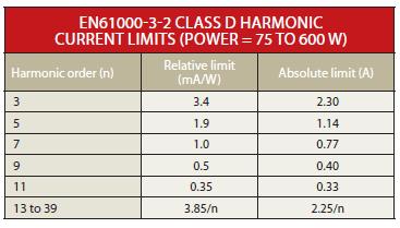
11 IEC/EN
12 Definition PF = Real P ower Apparent P ower Apparent Power = V rms x I rms PF = P p P 2 + Q 2 PF = 1 p 1+THD 2 = I 1,rms I rms
13
14
15
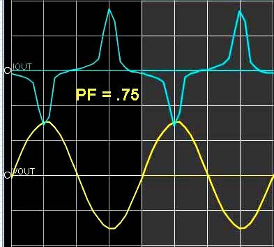
16 Power Factor in Littlebox Must drive load with PF between 0.7 and 1 Current waveform may lead or lag voltage by 45 degrees.
17 PF = Voltage Current
18 PF = Voltage Current
19 PFC
20 Power Factor Correction Correct power factor by regulating input current To be instantaneously proportional to input voltage I = kv Makes circuit look like a resistor May change the constant k over time Often done in a separate input stage Trivially achieved with DCM boost input stage Can be accomplished with CCM boost input stage and current-mode control
21 AC current in DC current out
22 PFC Input Stage PFC Boost Forward Output Stage

23 DCM of Flyback 1kHz Input Frequency Constant Pulse Width
24 Two Other Strategies
25
26 LT1248 TYPICAL APPLICATI O U 300W, 382V Preregulator 90V TO 270V T 6A EMI FILTER + 750µH* IRF840 MURH860 1M 1% + V OUT 180µF 0.047µF R S 0.2Ω 20k 1% 20k 0.47µF 330k R REF 4k 0.1µF 4k 1nF 100pF 20k V CC = 18V** + 56µF 35V VA OUT V REF M OUT I SENSE PK LIM GND CA OUT V CC V CC 16V TO 10V + 7.5V V REF RUN V/2.2V + EN/SYNC 2.2V + M1 7µA 1M 4.7nF 50k 11 V SENSE 6 I AC 7.5V 7.9V 8 OVP 12µA 5V SS 13 EA k I A I B ONE SHOT 200ns I M = I A 2 I B 200µA 2 I M CA V + RUN OSC SYNC R R S Q 16V GTDR 16 10Ω 1N µF C SET 14 R SET 12 * ** 1. COILTRONICS CTX (TYPE 52 CORE) AIR MOVEMENT NEEDED AT POWER LEVEL GREATER THAN 250W. 2. COILTRONICS CTX (MAGNETICS Kool Mµ CORE) SEE START-UP AND SUPPLY VOLTAGE SECTION FOR V CC GENERATOR. THIS SCHOTTKY DIODE IS TO CLAMP GTDR WHEN MOS SWITCH TURNS OFF. PARASITIC INDUCTANCE AND GATE CAPACITANCE MAY TURN ON CHIP SUBSTRATE DIODE AND CAUSE ERRATIC OPERATIONS IF GTDR IS NOT CLAMPED. 1000pF 15k 1248 TA01
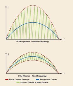
27 Summary of PFC Input current must be proportional to input voltage Harmonics limited by regulation PFC input stage regulates input current DCM constant pulse width CCM multiply input voltage by voltage error signal and regulate current to this value CrCM Constant on-time variable frequency Feedback tracks Input current to make it proportional to input voltage Output voltage sets constant of proportionality
28 Inverters
29 Inverter PFC regulates an AC input current Converts AC power to DC power Inverter regulates an AC output voltage Converts DC power to AC power Particularly useful for motor drives
30 Basic Inverter Make a Square Wave and Filter
31 Basic Inverter Make a Square Wave and Filter
32 But Filtering a 60Hz Square Wave is Hard
33 Spectrum of a 60Hz Square Wave Mag f (Hz)
34 Make a PWM Sine Wave and Filter
35 PWM Waveform V PWM (V) t (ms)
36 PWM Synthesis V AC, V Saw (V) V PWM (V) x = sine > saw y = -sine > saw Digitally generate sine with quarterwave table V Out (V) I L (A) t (ms)
37 100kHz PWM, 60Hz Sine (1667:1) 1.5 V AC, V Saw (V) V PWM (V) V Out (V) I L (A) t (ms)
38 Spectrum of 100kHz PWM Signal 9 x Mag f (Hz)
39 Circuit Simulation
40 SPICE Waveforms
41 Close Up of 2 PWM Cycles
42 Inverter Details Can operate independently or drive the grid. Grid connected inverters use the AC line as a sine-wave reference. This gives the proper phase It also compensates for distortion of the sine wave Current-mode control often used To give close to unity power factor into AC line This is the same as a PFC circuit but the current is flowing the other way
43 Anti-Islanding Grid-connected inverters need to turn off when the grid goes down. Safety issue for firemen, linemen, etc How do you detect when the grid goes down?
44 Anti-Islanding Line monitoring Voltage limits, frequency limits. Rate of change of frequency Rapid phase shift Active detection Impedance measurement Forced phase shift/frequency shift
45 Littlebox Inverter VP M1 L1 Input bypass network D1 30uH 12A RS V DC SC Storage capacitor 60x 2.2uF 450V X7T M6 M8 OA VN Inrush Prot L2 100uH 7A D2 M2 C1 M3 M4 L3 100uH 7A C2 0.47uF 600V M5 M7 0.47uF 600V C3 240V AC OB Generates rectified sinewave (RS) then unfolds it with a FET bridge why?
46 Inverters Summary Convert a DC Voltage to an AC Voltage AC is just slowly changing DC Use a full-bridge to generate a PWM Sine Wave Pulse width proportional to sin(x) LC Filter to reject high frequencies
47 Questions?
48 Upcoming Lectures HW Lab Lecture Date Topic out in out in Lab Descrip3on Homework Descrip3on Sep Introduc3on to Green Electronics, Boost, 1 1 Introduc3on to AVR Microcontroller Periodic Steady State Buck, and periodic steady state analysis Sep Real- 3me embedded sojware Sep Motors and Modeling AC energy meter Motor Calcula3ons 4 2- Oct Power MOSFETs, SPICE simula3on 5 7- Oct Power circuits Motor control - Matlab Power devices 6 9- Oct Feedback Control Oct PV Cells, Op3miza3on, Finding Peak Power Motor control - Lab Feedback Oct Transformers and bridge converters Oct Magne3cs PV power- point tracker PV Oct SoJ switching Oct Inverters Power supply part 1/Project Magne3cs design Proposal Oct Solar Day l Nov Ba\eries Power supply part 2 Bridge converter Nov Grounding and debugging Nov Review for Midterm 6 P 7 Project Nov Mar3n Fornage (Enphase) MT 13- Nov Midterm Nov Colin Campbell (Tesla) C Nov Andrew Ponec (SunPower/Dragonfly) Dec Wrapup Lecture C Dec Project Presenta3ons P Project Report Due - Website
EE155/255 Green Electronics
 EE155/255 Green Electronics Quiz Review 11/14/16 Prof. William Dally Computer Systems Laboratory Stanford University Quiz is next Wednesday 11/16 7:00PM to 9:00PM Room 200-203 Covers all material to date
EE155/255 Green Electronics
 EE155/255 Green Electronics Embedded Software Power Devices 10/2/17 Prof. William Dally Computer Systems Laboratory Stanford University EE155/255 F17 L3 2 Lab group assignments Logistics Go to Canvas and
Lecture 4 ECEN 4517/5517
 Lecture 4 ECEN 4517/5517 Experiment 3 weeks 2 and 3: interleaved flyback and feedback loop Battery 12 VDC HVDC: 120-200 VDC DC-DC converter Isolated flyback DC-AC inverter H-bridge v ac AC load 120 Vrms
EE155/255 Green Electronics
 EE155/255 Green Electronics Power Circuits Photovoltaics 10/5/16 Prof. William Dally Computer Systems Laboratory Stanford University HW2 due Monday 10/10 Lab1 signed off this week Lab2 out Course Logistics
EE152 Green Electronics
 EE152 Green Electronics Power Circuits Photovoltaics 9/30/15 Prof. William Dally Computer Systems Laboratory Stanford University Course Logistics HW2 out Today due Monday 10/5 Lab1 signed off this week
EE155/255 Green Electronics
 EE155/255 Green Electronics Thermal and EMI 11/7/16 Prof. William Dally Computer Systems Laboratory Stanford University No Date Topic HW out HW in Lab out Lab ck Lab HW 1 9/26/16 Intro (basic converters)
CHAPTER 6 BRIDGELESS PFC CUK CONVERTER FED PMBLDC MOTOR
 105 CHAPTER 6 BRIDGELESS PFC CUK CONVERTER FED PMBLDC MOTOR 6.1 GENERAL The line current drawn by the conventional diode rectifier filter capacitor is peaked pulse current. This results in utility line
Constant Current Switching Regulator for White LED
 Constant Current Switching Regulator for White LED FP7201 General Description The FP7201 is a Boost DC-DC converter specifically designed to drive white LEDs with constant current. The device can support
CHAPTER 2 A SERIES PARALLEL RESONANT CONVERTER WITH OPEN LOOP CONTROL
 14 CHAPTER 2 A SERIES PARALLEL RESONANT CONVERTER WITH OPEN LOOP CONTROL 2.1 INTRODUCTION Power electronics devices have many advantages over the traditional power devices in many aspects such as converting
Lecture 6 ECEN 4517/5517
 Lecture 6 ECEN 4517/5517 Experiment 4: inverter system Battery 12 VDC HVDC: 120-200 VDC DC-DC converter Isolated flyback DC-AC inverter H-bridge v ac AC load 120 Vrms 60 Hz d d Feedback controller V ref
Lab 9: 3 phase Inverters and Snubbers
 Lab 9: 3 phase Inverters and Snubbers Name: Pre Lab 3 phase inverters: Three phase inverters can be realized in two ways: three single phase inverters operating together, or one three phase inverter. The
Examples Paper 3B3/4 DC-AC Inverters, Resonant Converter Circuits. dc to ac converters
 Straightforward questions are marked! Tripos standard questions are marked * Examples Paper 3B3/4 DC-AC Inverters, Resonant Converter Circuits dc to ac converters! 1. A three-phase bridge converter using
idesyn id8802 2A, 23V, Synchronous Step-Down DC/DC
 2A, 23V, Synchronous Step-Down DC/DC General Description Applications The id8802 is a 340kHz fixed frequency PWM synchronous step-down regulator. The id8802 is operated from 4.5V to 23V, the generated
Reduction of Voltage Stresses in Buck-Boost-Type Power Factor Correctors Operating in Boundary Conduction Mode
 Reduction of oltage Stresses in Buck-Boost-Type Power Factor Correctors Operating in Boundary Conduction Mode ars Petersen Institute of Electric Power Engineering Technical University of Denmark Building
Low-Noise 4.5A Step-Up Current Mode PWM Converter
 Low-Noise 4.5A Step-Up Current Mode PWM Converter FP6298 General Description The FP6298 is a current mode boost DC-DC converter. It is PWM circuitry with built-in 0.08Ω power MOSFET make this regulator
Lecture 19 - Single-phase square-wave inverter
 Lecture 19 - Single-phase square-wave inverter 1. Introduction Inverter circuits supply AC voltage or current to a load from a DC supply. A DC source, often obtained from an AC-DC rectifier, is converted
In this lab you will build a photovoltaic controller that controls a single panel and optimizes its operating point driving a resistive load.
 EE 155/255 Lab #3 Revision 1, October 10, 2017 Lab3: PV MPPT Photovoltaic cells are a great source of renewable energy. With the sun directly overhead, there is about 1kW of solar energy (energetic photons)
WD3119 WD3119. High Efficiency, 40V Step-Up White LED Driver. Descriptions. Features. Applications. Order information 3119 FCYW 3119 YYWW
 High Efficiency, 40V Step-Up White LED Driver Http//:www.sh-willsemi.com Descriptions The is a constant current, high efficiency LED driver. Internal MOSFET can drive up to 10 white LEDs in series and
Chapter 6 Soft-Switching dc-dc Converters Outlines
 Chapter 6 Soft-Switching dc-dc Converters Outlines Classification of soft-switching resonant converters Advantages and disadvantages of ZCS and ZVS Zero-current switching topologies The resonant switch
Power Factor Pre-regulator Using Constant Tolerance Band Control Scheme
 Power Factor Pre-regulator Using Constant Tolerance Band Control Scheme Akanksha Mishra, Anamika Upadhyay Akanksha Mishra is a lecturer ABIT, Cuttack, India (Email: misakanksha@gmail.com) Anamika Upadhyay
Fundamentals of Power Electronics
 Fundamentals of Power Electronics SECOND EDITION Robert W. Erickson Dragan Maksimovic University of Colorado Boulder, Colorado Preface 1 Introduction 1 1.1 Introduction to Power Processing 1 1.2 Several
Lecture 8 ECEN 4517/5517
 Lecture 8 ECEN 4517/5517 Experiment 4 Lecture 7: Step-up dcdc converter and PWM chip Lecture 8: Design of analog feedback loop Part I Controller IC: Demonstrate operating PWM controller IC (UC 3525) Part
ECEN 5817 Resonant and Soft-Switching Techniques in Power Electronics. ECEN5817 website:
 Resonant and Soft-Switching Techniques in Power Electronics Instructor: Dragan Maksimovic office: ECOT 346 phone: 303-492-4863 maksimov@colorado.edu Prerequisite: ECEN5797 Introduction to Power Electronics
ECEN 5807 Modeling and Control of Power Electronic Systems
 ECEN 5807 Modeling and Control of Power Electronic Systems Instructor: Prof. Bob Erickson Office telephone: (303) 492-7003 Fax: (303) 492-2758 Email: rwe@colorado.edu Course web page http://ece.colorado.edu/~ecen5807
FAN Pin PFC and PWM Controller Combo. Features. General Description. Block Diagram.
 8-Pin PFC and PWM Controller Combo www.fairchildsemi.com Features Internally synchronized PFC and PWM in one 8-pin IC Patented one-pin voltage error amplifier with advanced input current shaping technique
WD3122EC. Descriptions. Features. Applications. Order information. High Efficiency, 28 LEDS White LED Driver. Product specification
 High Efficiency, 28 LEDS White LED Driver Descriptions The is a constant current, high efficiency LED driver. Internal MOSFET can drive up to 10 white LEDs in series and 3S9P LEDs with minimum 1.1A current
Thermally enhanced Low V FB Step-Down LED Driver ADT6780
 Thermally enhanced Low V FB Step-Down LED Driver General Description The is a thermally enhanced current mode step down LED driver. That is designed to deliver constant current to high power LEDs. The
CHAPTER 3. SINGLE-STAGE PFC TOPOLOGY GENERALIZATION AND VARIATIONS
 CHAPTER 3. SINGLE-STAGE PFC TOPOLOG GENERALIATION AND VARIATIONS 3.1. INTRODUCTION The original DCM S 2 PFC topology offers a simple integration of the DCM boost rectifier and the PWM DC/DC converter.
CHAPTER 4 PI CONTROLLER BASED LCL RESONANT CONVERTER
 61 CHAPTER 4 PI CONTROLLER BASED LCL RESONANT CONVERTER This Chapter deals with the procedure of embedding PI controller in the ARM processor LPC2148. The error signal which is generated from the reference
DESCRIPTION FEATURES PROTECTION FEATURES APPLICATIONS. RS2320 High Accurate Non-Isolated Buck LED Driver
 High Accurate Non-Isolated Buck LED Driver DESCRIPTION RS2320 is especially designed for non-isolated LED driver. The building in perfect current compensation function ensures the accurate output current.
Comparison Between two Single-Switch Isolated Flyback and Forward High-Quality Rectifiers for Low Power Applications
 Comparison Between two ingle-witch Isolated Flyback and Forward High-Quality Rectifiers for Low Power Applications G. piazzi,. Buso Department of Electronics and Informatics - University of Padova Via
Non-Synchronous PWM Boost Controller for LED Driver
 Non-Synchronous PWM Boost Controller for LED Driver General Description The is boost topology switching regulator for LED driver. It provides built-in gate driver pin for driving external N-MOSFET. The
RT8465. Constant Voltage High Power Factor PWM Boost Driver Controller for MR16 Application. Features. General Description.
 RT8465 Constant Voltage High Power Factor PWM Boost Driver Controller for MR16 Application General Description The RT8465 is a constant output voltage, active high power factor, PWM Boost driver controller.
IMPLEMENTATION OF A DOUBLE AC/DC/AC CONVERTER WITH POWER FACTOR CORRECTION (PFC) FOR NON-LINEAR LOAD APPLICATIONS
 FOR NON-LINEAR LOAD APPLICATIONS") IMPLEMENTATION OF A DOUBLE AC/DC/AC CONERTER WITH POWER FACTOR CORRECTION (PFC) FOR NON-LINEAR LOAD APPLICATIONS E.Alvear 1, M.Sanchez 1 and J.Posada 2 1 Department of Automation and Electronics, Electronics
IMPLEMENTATION OF A DOUBLE AC/DC/AC CONERTER WITH POWER FACTOR CORRECTION (PFC) FOR NON-LINEAR LOAD APPLICATIONS E.Alvear 1, M.Sanchez 1 and J.Posada 2 1 Department of Automation and Electronics, Electronics
Design and Simulation of New Efficient Bridgeless AC- DC CUK Rectifier for PFC Application
 Design and Simulation of New Efficient Bridgeless AC- DC CUK Rectifier for PFC Application Thomas Mathew.T PG Student, St. Joseph s College of Engineering, C.Naresh, M.E.(P.hd) Associate Professor, St.
LSP5502 2A Synchronous Step Down DC/DC Converter
 FEATURES 2A Output Current Wide 4.5V to 27V Operating Input Range Integrated 20mΩ Power MOSFET Switches Output Adjustable from 0.925V to 24V Up to 96% Efficiency Programmable Soft-Start Stable with Low
Current Rebuilding Concept Applied to Boost CCM for PF Correction
 Current Rebuilding Concept Applied to Boost CCM for PF Correction Sindhu.K.S 1, B. Devi Vighneshwari 2 1, 2 Department of Electrical & Electronics Engineering, The Oxford College of Engineering, Bangalore-560068,
Non-Synchronous PWM Boost Controller
 Non-Synchronous PWM Boost Controller FP5209 General Description The FP5209 is a boost topology switching regulator for wide operating voltage applications. It provides built-in gate driver pin, EXT pin,
ACT111A. 4.8V to 30V Input, 1.5A LED Driver with Dimming Control GENERAL DESCRIPTION FEATURES APPLICATIONS TYPICAL APPLICATION CIRCUIT
 4.8V to 30V Input, 1.5A LED Driver with Dimming Control FEATURES Up to 92% Efficiency Wide 4.8V to 30V Input Voltage Range 100mV Low Feedback Voltage 1.5A High Output Capacity PWM Dimming 10kHz Maximum
R. W. Erickson. Department of Electrical, Computer, and Energy Engineering University of Colorado, Boulder
 R. W. Erickson Department of Electrical, Computer, and Energy Engineering University of Colorado, Boulder 18.2.2 DCM flyback converter v ac i ac EMI filter i g v g Flyback converter n : 1 L D 1 i v C R
Interleaved PFC technology bring up low ripple and high efficiency
 Interleaved PFC technology bring up low ripple and high efficiency Tony Huang 黄福恩 Texas Instrument Sept 12,2007 1 Presentation Outline Introduction to Interleaved transition mode PFC Comparison to single-channel
An Improved CSI with the Use of Hybrid PWM and Passive Resonant Snubber Latha. R 1,Walter raja rajan.b 2
 International Journal of Advances in Electrical and Electronics Engineering 158 Available online at www.ijaeee.com & www.sestindia.org ISSN: 2319-1112 An Improved CSI with the Use of Hybrid PWM and Passive
40V Boost Converter for LED driver / TFT Bias / USB Power
 40V Boost Converter for LED driver / TFT Bias / USB Power DESCRIPTION The is a high efficiency step-up converter with an internally integrated 40V power MOSEFT. It runs with an optimal 0.8MHz frequency
Not Recommended for New Designs
 Not Recommended for New Designs This product was manufactured for Maxim by an outside wafer foundry using a process that is no longer available. It is not recommended for new designs. The data sheet remains
High Accurate non-isolated Buck LED Driver
 High Accurate non-isolated Buck LED Driver Features High efficiency (More than 90%) High precision output current regulation (-3%~+3%) when universal AC input voltage (85VAC~265VAC) Lowest cost and very
Application Note AN-1075
 Application Note AN-1075 Obtaining Low THD and high PF without A PFC By Cecilia Contenti and Peter Green Table of Contents Page I. Introduction...1 II. Test Results...1 III. Electrical Circuit...2 IV.
CHAPTER 2 AN ANALYSIS OF LC COUPLED SOFT SWITCHING TECHNIQUE FOR IBC OPERATED IN LOWER DUTY CYCLE
 40 CHAPTER 2 AN ANALYSIS OF LC COUPLED SOFT SWITCHING TECHNIQUE FOR IBC OPERATED IN LOWER DUTY CYCLE 2.1 INTRODUCTION Interleaving technique in the boost converter effectively reduces the ripple current
A HIGH RELIABILITY SINGLE-PHASE BOOST RECTIFIER SYSTEM FOR DIFFERENT LOAD VARIATIONS. Prasanna Srikanth Polisetty
 GRT A HIGH RELIABILITY SINGLE-PHASE BOOST RECTIFIER SYSTEM FOR DIFFERENT LOAD VARIATIONS Prasanna Srikanth Polisetty Department of Electrical and Electronics Engineering, Newton s College of Engineering
GaN in Practical Applications
 in Practical Applications 1 CCM Totem Pole PFC 2 PFC: applications and topology Typical AC/DC PSU 85-265 V AC 400V DC for industrial, medical, PFC LLC 12, 24, 48V DC telecomm and server applications. PFC
Using the EVM: PFC Design Tips and Techniques
 PFC Design Tips and Techniques Features: Bare die attach with epoxy Gold wire bondable Integral precision resistors Reduced size and weight High temperature operation Solder ready surfaces for flip chips
CEP8113A Rev 2.0, Apr, 2014
 Wide-Input Sensorless CC/CV Step-Down DC/DC Converter FEATURES 42V Input Voltage Surge 40V Steady State Operation Up to 3.5A output current Output Voltage 2.5V to 10V Resistor Programmable Current Limit
4.5V to 32V Input High Current LED Driver IC For Buck or Buck-Boost Topology CN5816. Features: SHDN COMP OVP CSP CSN
 4.5V to 32V Input High Current LED Driver IC For Buck or Buck-Boost Topology CN5816 General Description: The CN5816 is a current mode fixed-frequency PWM controller for high current LED applications. The
R. W. Erickson. Department of Electrical, Computer, and Energy Engineering University of Colorado, Boulder
 R. W. Erickson Department of Electrical, Computer, and Energy Engineering University of Colorado, Boulder 17.1 The single-phase full-wave rectifier i g i L L D 4 D 1 v g Z i C v R D 3 D 2 Full-wave rectifier
Three Phase PFC and Harmonic Mitigation Using Buck Boost Converter Topology
 Three Phase PFC and Harmonic Mitigation Using Buck Boost Converter Topology Riya Philip 1, Reshmi V 2 Department of Electrical and Electronics, Amal Jyothi College of Engineering, Koovapally, India 1,
1.5MHz, 1A Synchronous Step-Down Regulator
 1.5MHz, 1A Synchronous Step-Down Regulator FP6161 General Description The FP6161 is a high efficiency current mode synchronous buck PWM DC-DC regulator. The internal generated 0.6V precision feedback reference
Soft-Switching Two-Switch Resonant Ac-Dc Converter
 Soft-Switching Two-Switch Resonant Ac-Dc Converter Aqulin Ouseph 1, Prof. Kiran Boby 2,, Prof. Dinto Mathew 3 1 PG Scholar,Department of Electrical and Electronics Engineering, Mar Athanasius College of
6. Explain control characteristics of GTO, MCT, SITH with the help of waveforms and circuit diagrams.
 POWER ELECTRONICS QUESTION BANK Unit 1: Introduction 1. Explain the control characteristics of SCR and GTO with circuit diagrams, and waveforms of control signal and output voltage. 2. Explain the different
14. DC to AC Converters
 14. DC to AC Converters Single-phase inverters: 14.1 Single-phase half-bridge inverter This type of inverter is very simple in construction. It does not need output transformer like parallel inverter.
Speed control of power factor corrected converter fed BLDC motor
 Speed control of power factor corrected converter fed BLDC motor Rahul P. Argelwar 1, Suraj A. Dahat 2 Assistant Professor, Datta Meghe institude of Engineering, Technology & Research,Wardha. 1 Assistant
Design and Implementation of Photovoltaic Inverter system using Multi-cell Interleaved Fly-back Topology
 International Journal of ChemTech Research CODEN (USA): IJCRGG, ISSN: 0974-4290, ISSN(Online):2455-9555 Vol.10 No.14, pp 300-308, 2017 Design and Implementation of Photovoltaic Inverter system using Multi-cell
ANP012. Contents. Application Note AP2004 Buck Controller
 Contents 1. AP004 Specifications 1.1 Features 1. General Description 1. Pin Assignments 1.4 Pin Descriptions 1.5 Block Diagram 1.6 Absolute Maximum Ratings. Hardware.1 Introduction. Typical Application.
Application of GaN Device to MHz Operating Grid-Tied Inverter Using Discontinuous Current Mode for Compact and Efficient Power Conversion
 IEEE PEDS 2017, Honolulu, USA 12-15 December 2017 Application of GaN Device to MHz Operating Grid-Tied Inverter Using Discontinuous Current Mode for Compact and Efficient Power Conversion Daichi Yamanodera
MIC38C42A/43A/44A/45A
 MIC38C42A/43A/44A/45A BiCMOS Current-Mode PWM Controllers General Description The MIC38C4xA are fixed frequency, high performance, current-mode PWM controllers. Micrel s BiCMOS devices are pin compatible
Designing High-Efficiency ATX Solutions. Practical Design Considerations & Results from a 255 W Reference Design
 Designing High-Efficiency ATX Solutions Practical Design Considerations & Results from a 255 W Reference Design Agenda Regulation and Market Requirements Target Specification for the Reference Design Architectural
Bridgeless Cuk Power Factor Corrector with Regulated Output Voltage
 Bridgeless Cuk Power Factor Corrector with Regulated Output Voltage Ajeesh P R 1, Prof. Dinto Mathew 2, Prof. Sera Mathew 3 1 PG Scholar, 2,3 Professors, Department of Electrical and Electronics Engineering,
ADT7351. General Description. Applications. Features. Typical Application Circuit. Oct / Rev0.
 General Description The ADT735 is a step-down converter with integrated switching MOSFET. It operates wide input supply voltage range from 4.5 to 28 with 3A continuous output current. It includes current
Low-Cost, High-Voltage, Internally Powered OUTPUT ISOLATION AMPLIFIER
 Low-Cost, High-Voltage, Internally Powered OUTPUT ISOLATION AMPLIFIER FEATURES SELF-CONTAINED ISOLATED SIGNAL AND OUTPUT POWER SMALL PACKAGE SIZE: Double-Wide (.6") Sidebraze DIP CONTINUOUS AC BARRIER
1.5MHz, 2A Synchronous Step-Down Regulator
 1.5MHz, 2A Synchronous Step-Down Regulator General Description The is a high efficiency current mode synchronous buck PWM DC-DC regulator. The internal generated 0.6V precision feedback reference voltage
ZCS-PWM Converter for Reducing Switching Losses
 IOSR Journal of Electrical and Electronics Engineering (IOSR-JEEE) e-issn: 2278-1676,p-ISSN: 2320-3331, Volume 9, Issue 1 Ver. III (Jan. 2014), PP 29-35 ZCS-PWM Converter for Reducing Switching Losses
Incorporating Active-Clamp Technology to Maximize Efficiency in Flyback and Forward Designs
 Topic 2 Incorporating Active-Clamp Technology to Maximize Efficiency in Flyback and Forward Designs Bing Lu Agenda 1. Basic Operation of Flyback and Forward Converters 2. Active Clamp Operation and Benefits
1.5MHz, 3A Synchronous Step-Down Regulator
 1.5MHz, 3A Synchronous Step-Down Regulator FP6165 General Description The FP6165 is a high efficiency current mode synchronous buck PWM DC-DC regulator. The internal generated 0.6V precision feedback reference
ZCS BRIDGELESS BOOST PFC RECTIFIER Anna Joy 1, Neena Mani 2, Acy M Kottalil 3 1 PG student,
 ZCS BRIDGELESS BOOST PFC RECTIFIER Anna Joy 1, Neena Mani 2, Acy M Kottalil 3 1 PG student, annajoykandathil@gmail.com,8111948255 Abstract A new bridgeless single-phase ac dc converter with a natural power
Power quality improvement and ripple cancellation in zeta converters
 Power quality improvement and ripple cancellation in zeta converters Mariamma John 1, Jois.K.George 2 1 Student, Kottayam Institute of Technology and Science, Chengalam, Kottayam, India 2Assistant Professor,
DC-DC Resonant converters with APWM control
 IOSR Journal of Electrical and Electronics Engineering (IOSR-JEEE) ISSN: 2278-1676 Volume 2, Issue 5 (Sep-Oct. 2012), PP 43-49 DC-DC Resonant converters with APWM control Preeta John 1 Electronics Department,
SC A LED DRIVER with INTERNAL SWITCH. Features. Description. Applications. Package Information
 1.2A LED DRVER with NTERNAL SWTCH Features Simple low parts count Wide input voltage range: 4V to 40V 1.2A output current Single pin on/off Brightness control by using DC voltage Brightness control by
Modified SEPIC PFC Converter for Improved Power Factor and Low Harmonic Distortion
 Modified SEPIC PFC Converter for Improved Power Factor and Low Harmonic Distortion Amrutha M P 1, Priya G Das 2 1, 2 Department of EEE, Abdul Kalam Technological University, Palakkad, Kerala, India-678008
Constant-Frequency Soft-Switching Converters. Soft-switching converters with constant switching frequency
 Constant-Frequency Soft-Switching Converters Introduction and a brief survey Active-clamp (auxiliary-switch) soft-switching converters, Active-clamp forward converter Textbook 20.4.2 and on-line notes
CHAPTER 4 DESIGN OF CUK CONVERTER-BASED MPPT SYSTEM WITH VARIOUS CONTROL METHODS
 68 CHAPTER 4 DESIGN OF CUK CONVERTER-BASED MPPT SYSTEM WITH VARIOUS CONTROL METHODS 4.1 INTRODUCTION The main objective of this research work is to implement and compare four control methods, i.e., PWM
CEP8101A Rev 1.0, Apr, 2014
 Wide-Input Sensorless CC/CV Step-Down DC/DC Converter FEATURES 42V Input Voltage Surge 40V Steady State Operation Up to 2.1A output current Output Voltage 2.5V to 10V Resistor Programmable Current Limit
Power Factor Corrected Single Stage AC-DC Full Bridge Resonant Converter
 Power Factor Corrected Single Stage AC-DC Full Bridge Resonant Converter Gokul P H Mar Baselios College of Engineering Mar Ivanios Vidya Nagar, Nalanchira C Sojy Rajan Assisstant Professor Mar Baselios
Demonstration. Agenda
 Demonstration Edward Lee 2009 Microchip Technology, Inc. 1 Agenda 1. Buck/Boost Board with Explorer 16 2. AC/DC Reference Design 3. Pure Sinewave Inverter Reference Design 4. Interleaved PFC Reference
Lecture Note. DC-AC PWM Inverters. Prepared by Dr. Oday A Ahmed Website: https://odayahmeduot.wordpress.com
 Lecture Note 10 DC-AC PWM Inverters Prepared by Dr. Oday A Ahmed Website: https://odayahmeduot.wordpress.com Email: 30205@uotechnology.edu.iq Scan QR DC-AC PWM Inverters Inverters are AC converters used
The FMMT718 Range, Features and Applications
 The Range, Features and Applications Replacing SOT89, SOT223 and D-Pak Products with High Current SOT23 Bipolar Transistors. David Bradbury Neil Chadderton Designers of surface mount products wishing to
ACEEE Int. J. on Control System and Instrumentation, Vol. 02, No. 02, June 2011
 A New Active Snubber Circuit for PFC Converter Burak Akýn Yildiz Technical University/Electrical Engineering Department Istanbul TURKEY Email: bakin@yildizedutr ABSTRACT In this paper a new active snubber
10kW Three-phase SiC PFC Rectifier
 www.onsemi.com 10kW Three-phase SiC PFC Rectifier SEMICON EUROPA, Nov 13-18, 2018, Munich, Germany Contents General PFC Concept 3 Phase System and PFC Control Simulation Understanding the losses 3 Phase
Boundary Mode Offline LED Driver Using MP4000. Application Note
 The Future of Analog IC Technology AN046 Boundary Mode Offline LED Driver Using MP4000 Boundary Mode Offline LED Driver Using MP4000 Application Note Prepared by Zheng Luo March 25, 2011 AN046 Rev. 1.0
MP1482 2A, 18V Synchronous Rectified Step-Down Converter
 The Future of Analog IC Technology MY MP48 A, 8 Synchronous Rectified Step-Down Converter DESCRIPTION The MP48 is a monolithic synchronous buck regulator. The device integrates two 30mΩ MOSFETs, and provides
LR8509 Series 1.5MHz 600mA Synchronous Step-Down Converter
 LR8509 Series 1.5MHz 600mA Synchronous Step-Down Converter INTRODUCTION: The LR8509 is a 1.5MHz constant frequency, slope compensated current mode PWM synchronous step-down converter. High switching frequency
Designing High density Power Solutions with GaN Created by: Masoud Beheshti Presented by: Xaver Arbinger
 Designing High density Power Solutions with GaN Created by: Masoud Beheshti Presented by: Xaver Arbinger Topics Why GaN? Integration for Higher System Performance Application Examples Taking GaN beyond
FP6276B 500kHz 6A High Efficiency Synchronous PWM Boost Converter
 500kHz 6A High Efficiency Synchronous PWM Boost Converter General Description The is a current mode boost DC-DC converter with PWM/PSM control. Its PWM circuitry with built-in 40mΩ high side switch and
POWER MANAGEMENT PRODUCTS. Application Note. Simple PWM Boost Converter with I/O Disconnect Solves Malfunctions Caused when V OUT <V IN
 POWER MANAGEMENT PRODUCTS Application Note Simple PWM Boost Converter with I/O Disconnect Solves Malfunctions Caused when V OUT
Low-Cost, Internally Powered ISOLATION AMPLIFIER
 Low-Cost, Internally Powered ISOLATION AMPLIFIER FEATURES SIGNAL AND POWER IN ONE DOUBLE-WIDE (.6") SIDE-BRAZED PACKAGE 56Vpk TEST VOLTAGE 15Vrms CONTINUOUS AC BARRIER RATING WIDE INPUT SIGNAL RANGE: V
Green-Mode PWM Controller with Integrated Protections
 Green-Mode PWM Controller with Integrated Protections Features Current mode PWM Very low startup current Under-voltage lockout (UVLO) Non-audible-noise green-mode control Programmable switching frequency
DIO8650 buck boost-80v235ma- THD<5% for LED T-tube lighting
 DEMO EVALUATION REPORT DIO8650 buck boost-80v235ma- THD
Simulation of Fuzzy Controller based Isolated Zeta Converter fed BLDC motor drive
 Simulation of Fuzzy Controller based Isolated Zeta Converter fed BLDC motor drive 1 Sreelakshmi K, 2 Caroline Ann Sam 1 PG Student 2 Asst.Professor 1 EEE Department, 1 Rajagiri School of Engineering and
Design of step-up converter for a constant output in a high power design
 2015; 1(6): 125-129 ISSN Print: 2394-7500 ISSN Online: 2394-5869 Impact Factor: 3.4 IJAR 2015; 1(6): 125-129 www.allresearchjournal.com Received: 25-03-2015 Accepted: 27-04-2015 M. Tech, (VLSI Design and
POWER ISIPO 29 ISIPO 27
 SI NO. TOPICS FIELD ISIPO 01 A Low-Cost Digital Control Scheme for Brushless DC Motor Drives in Domestic Applications ISIPO 02 A Three-Level Full-Bridge Zero-Voltage Zero-Current Switching With a Simplified
UC3855A/B HIGH PERFORMANCE POWER FACTOR PREREGULATOR
 UNITRODE CORPORATION UC3855A/B HIGH PERFORMANCE POWER FACTOR PREREGULATOR James P. Noon New Product Applications Engineer INTRODUCTION The trend in power converters is towards increasingly higher power
D8020. Universal High Integration Led Driver Description. Features. Typical Applications
 Universal High Integration Led Driver Description The D8020 is a highly integrated Pulse Width Modulated (PWM) high efficiency LED driver IC. It requires as few as 6 external components. This IC allows
Power Management for Computer Systems. Prof. C Wang
 ECE 5990 Power Management for Computer Systems Prof. C Wang Fall 2010 Course Outline Fundamental of Power Electronics cs for Computer Systems, Handheld Devices, Laptops, etc More emphasis in DC DC converter