Demonstration. Agenda
|
|
|
- Theodore Miles
- 6 years ago
- Views:
Transcription
1 Demonstration Edward Lee 2009 Microchip Technology, Inc. 1 Agenda 1. Buck/Boost Board with Explorer AC/DC Reference Design 3. Pure Sinewave Inverter Reference Design 4. Interleaved PFC Reference Design W DC/DC Converter 2
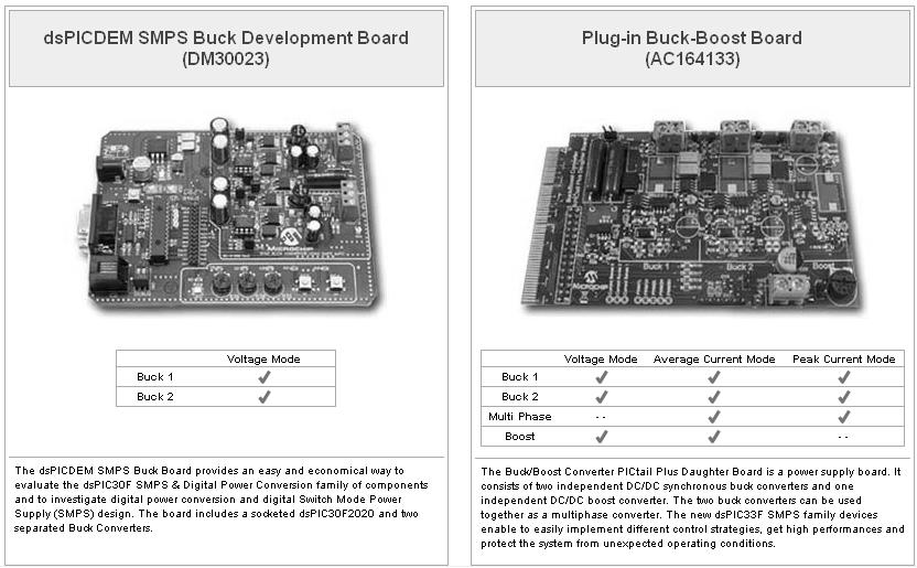
2 Buck/Buck-Boost + Mindi GUI 3 4
3 General Configuration 5 General Configuration Soft Start - Sequencing Header file: Config_General.h 6


4 Design Options Topology 7 Design Options Advanced 8

5 Design Options Schematic 9 Design Options Schematic 10


6 Design Options Schematic BODE PLOT STEADY STATE ANALYSIS TRANSIENT ANALYSIS 11 Design Options Schematic Bode Plot 12


7 Design Options Design Summary 13 My Design DESIGN NAME DESIGN DESCRIPTION SAVE BUTTON 14


8 Downloads BOM 15 AC-DC Reference Design Ac-dc Reference Design We will use it to investigate the following items: 1. PFC implementation 2. Soft Switching 3. Multiphase Implementation 4. Comparator 16
9 Block Diagram Isolation Barrier Vac 45-65Hz EMI Filter And Bridge Rectifier Rectified Sinusoidal Voltage PFC Boost Converter 400 Vdc Full Bridge Converter DC-DC Converter Sync Rectifier and Filter Multi-phase Buck converter Single-phase Buck converter SMPS Controller Opto- Coupler Feedback Signal 17 AC-DC Reference Design PHASE SHIFT DC-DC MULTIPHASE DC-DC PFC CONTROL BOARD DC-DC EMI FILTER Main Building Blocks: EMI Filter PFC Phase shift dc-c Multiphase dc-dc Single phase dc-dc Control board 18

10 Pure Sinewave Inverter Reference Design CD-ROM with documentation and code Offline UPS Reference Design 3x 12V SLA Batteries Battery Input Cable Power Cord 2x Battery Jumper Cables 19 Offline UPS Offline UPS Switches to battery as it detects power failure Few millisecond switchover time at power failure Filter Transfer Switch DC DC DC AC Battery Charger Battery Boost Converter Inverter 20
11 Specifications Microchip s Offline UPS Reference Design: 1kVA Steady-State Power Battery Input Voltage 36V (3X12V) AC Voltage Pure Sine Wave 60Hz 50Hz Efficiency ~ 84% Transfer time < 10ms (from Mains to Battery Power) 21 Block Diagram 390V DC +12V +5V Auxiliary Power Supply Battery (3 x 12V) Boost Stage DC-Link Filter Full Bridge Inverter +3.3V Battery Charger (Flyback) dspic DSC 220Vac, 50Hz LC Filter Relay Logic Load AC Input 22
12 UPS Board Layout: Push-Pull Converter Push-Pull Primary Side Push-Pull Secondary Side DC Link Filter 23 UPS Board Layout: Full-Bridge Inverter Full-Bridge Current Sensor Filter Relay 24
13 UPS Board Layout: Flyback Battery Charger Flyback Battery Charger 25 UPS Board Layout: dspic & Other Circuitry USB Controller Auxiliary Power Supply LCD Controller dspic 26
14 Inverter Operation with Rectifier Loads Inverter Voltage Inverter Current Inverter becomes zero Large Inrush Current causes Driver Fault 27 Inverter Operation with Rectifier Loads Inverter Voltage Inverter Current Driver Fault Recovery Routine increments PWM duty cycle in small steps and charges load capacitor 28
15 Inverter Operation with Rectifier Loads Inverter Control Loop resumes when output voltage matches sine reference Inverter Voltage Inverter Current Edward Lee September Watt Interleaved PFC Edward Lee September
16 Interleaved PFC Operation PWM1 I IN I L1 I D1 I Load PWM1 I C PWM V AC PWM2 I L2 I s1 I s2 I D2 PFC output IL1 IL2 (IL1 + IL2) t When duty cycle is = 50% 31 Interleaved PFC Operation PWM1 I IN I L1 I D1 I Load PWM1 I C PWM2 I s V AC PWM2 I L2 I s2 I D2 PFC output IL1 IL2 (IL1 + IL2) When duty cycle is > 50% t 32
17 Advantages Interleaved PFC Less ripple current on the output capacitor Less ripple current in the input as inductor ripples cancel Total Inductor volume can be reduced (approx. ½ the size of single converter) by tolerating higher ripple current % (ripple cancelling) in individual converters compared to a single stage PFC 33 Basic Block Diagram D1 ~ L2 D2 + ~ PWM1 Q1 Q2 PWM2 DC Bus Voltage - V AC I AC IQ 1 IQ 2 A to D Converter V DC Digital Control System PWM Module PWM1 PWM2 Digital Signal Controller (dspic) 34
18 Control Methodology ACMC (Average Current Mode Control): Contains two PI loops: an inner current loop and an outer voltage loop The inner current loops run much faster than the outer voltage loop (50 khz versus 2 khz) and ensures that the average input current is in phase with the input voltage. The reference current for inductors is closely followed, as in a current controlled source CCM (Continuous Conduction Mode): Current in the inductor never goes to zero except at the input voltage zero crossing points (depending on the inductor values and the amount of load connected to the system) Operating in the continuous conduction region reduces the harmonic content on the input current I L 35 Electrical Specifications Line Input Voltage: 85 to 265 Volts (RMS) Line Frequency: 45 to 66 Hz Power: 350 watts Efficiency: 350 Watts Voltage: 400 Volts PF: 0.99 Regulation: +/- 1.5% output ripple 36
 Inductor Current (I")
19 Simulink Block Diagrams PFC System Model 37 Simulation Results Rectified Input Voltage ( V AC ) Inductor Current (I AC ) 38

20 200W DC/DC Converter 39 Block Diagram Q1 Q3 Tx 1 Q6 Gate Drive Q1- Q6 Q2 Q4 CT1 Q5 L 0 V o GND CMP4 High speed PWM +/- PHASE δphase dspic33fj16gs502 PI Control Phase + δi P Control δi L + I Ave δv PI Control - I Share ADC2 ADC0 + ADC1 - Targeted Voltage V * o 40


21 MATLAB simulations 41 Control System Simulation Voltage variation Settling time 500uSec Load Transient 0A - 9A 42
Digital Control IC for Interleaved PFCs
 Digital Control IC for Interleaved PFCs Rosario Attanasio Applications Manager STMicroelectronics Presentation Outline 2 PFC Basics Interleaved PFC Concept Analog Vs Digital Control The STNRGPF01 Digital
Digital Power Seminar
 Digital Power Seminar Agenda 1.What is Digital Power 2.Benefits of Digital Power 3.Digital Power Applications 4.Levels of Integration 5.Full Digital Control 6.Solutions from Microchip for Digital Power
Designing A Medium-Power Resonant LLC Converter Using The NCP1395
 Designing A Medium-Power Resonant LLC Converter Using The NCP395 Prepared by: Roman Stuler This document describes the design procedure needed to implement a medium-power LLC resonant AC/DC converter using
POWER ISIPO 29 ISIPO 27
 SI NO. TOPICS FIELD ISIPO 01 A Low-Cost Digital Control Scheme for Brushless DC Motor Drives in Domestic Applications ISIPO 02 A Three-Level Full-Bridge Zero-Voltage Zero-Current Switching With a Simplified
Lecture 4 ECEN 4517/5517
 Lecture 4 ECEN 4517/5517 Experiment 3 weeks 2 and 3: interleaved flyback and feedback loop Battery 12 VDC HVDC: 120-200 VDC DC-DC converter Isolated flyback DC-AC inverter H-bridge v ac AC load 120 Vrms
A NEW SINGLE STAGE THREE LEVEL ISOLATED PFC CONVERTER FOR LOW POWER APPLICATIONS
 A NEW SINGLE STAGE THREE LEVEL ISOLATED PFC CONVERTER FOR LOW POWER APPLICATIONS S.R.Venupriya 1, Nithyananthan.K 2, Ranjidharan.G 3, Santhosh.M 4,Sathiyadevan.A 5 1 Assistant professor, 2,3,4,5 Students
Lecture 8 ECEN 4517/5517
 Lecture 8 ECEN 4517/5517 Experiment 4 Lecture 7: Step-up dcdc converter and PWM chip Lecture 8: Design of analog feedback loop Part I Controller IC: Demonstrate operating PWM controller IC (UC 3525) Part
Ripple Minimization through Harmonic Elimination in Asymmetric Interleaved Multiphase dc-dc Converters
 Ripple Minimization through Harmonic Elimination in Asymmetric Interleaved Multiphase dc-dc Converters Abstract Introduction: Current ripple cancellation is an important feature of multiphase switching
Student Department of EEE (M.E-PED), 2 Assitant Professor of EEE Selvam College of Technology Namakkal, India
, 2 Assitant Professor of EEE Selvam College of Technology Namakkal, India") Design and Development of Single Phase Bridgeless Three Stage Interleaved Boost Converter with Fuzzy Logic Control System M.Pradeep kumar 1, M.Ramesh kannan 2 1 Student Department of EEE (M.E-PED), 2 Assitant
Design and Development of Single Phase Bridgeless Three Stage Interleaved Boost Converter with Fuzzy Logic Control System M.Pradeep kumar 1, M.Ramesh kannan 2 1 Student Department of EEE (M.E-PED), 2 Assitant
Design and Simulation of Synchronous Buck Converter for Microprocessor Applications
 Design and Simulation of Synchronous Buck Converter for Microprocessor Applications Lakshmi M Shankreppagol 1 1 Department of EEE, SDMCET,Dharwad, India Abstract: The power requirements for the microprocessor
Chapter 10 Switching DC Power Supplies
 Chapter 10 Switching One of the most important applications of power electronics 10-1 Linear Power Supplies Very poor efficiency and large weight and size 10-2 Switching DC Power Supply: Block Diagram
MAXREFDES116# ISOLATED 24V TO 5V 40W POWER SUPPLY
 System Board 6283 MAXREFDES116# ISOLATED 24V TO 5V 40W POWER SUPPLY Overview Maxim s power supply experts have designed and built a series of isolated, industrial power-supply reference designs. Each of
AN1421. Platinum-rated AC/DC Reference Design Using the dspic DSC ENERGY STAR AND THE CLIMATE SAVERS COMPUTING INITIATIVE (CSCI)
") Using the dspic DSC AN1421 Author: Andreas Reiter and Alex Dumais Microchip Technology Inc. ENERGY STAR AND THE CLIMATE SAVERS COMPUTING INITIATIVE (CSCI) Today, Green Power is one of the hottest topics
Using the dspic DSC AN1421 Author: Andreas Reiter and Alex Dumais Microchip Technology Inc. ENERGY STAR AND THE CLIMATE SAVERS COMPUTING INITIATIVE (CSCI) Today, Green Power is one of the hottest topics
A Single Stage CCM Zeta Micro inverter for Solar Photovoltaic AC Module. Abstract
 Page number 1 A Single Stage CCM Zeta Micro inverter for Solar Photovoltaic AC Module Introduction: Abstract Among various microinverters reported in literature, the most generic are two stage inverters
MODERN switching power converters require many features
 IEEE TRANSACTIONS ON POWER ELECTRONICS, VOL. 19, NO. 1, JANUARY 2004 87 A Parallel-Connected Single Phase Power Factor Correction Approach With Improved Efficiency Sangsun Kim, Member, IEEE, and Prasad
Power Factor Corrected Single Stage AC-DC Full Bridge Resonant Converter
 Power Factor Corrected Single Stage AC-DC Full Bridge Resonant Converter Gokul P H Mar Baselios College of Engineering Mar Ivanios Vidya Nagar, Nalanchira C Sojy Rajan Assisstant Professor Mar Baselios
AC-DC SMPS: Up to 15W Application Solutions
 AC-DC SMPS: Up to 15W Application Solutions Yehui Han Applications Engineer April 2017 Agenda 2 Introduction Flyback Topology Optimization Buck Topology Optimization Layout and EMI Optimization edesignsuite
SPECIFICATION EP 1000/1500/2000 Series
 UNINTERRUPTIBLE POWER SYSTEM SPECIFICATION EP 1000/1500/2000 Series Page 1 of 28 1.0 Revision Summary REVISION SECTION DESCRIPTION Formal Release Page 2 of 28 Table of Contents 1. Introduction. 4 2. Block
Renee Kohl Peter Burrmann Matthew Daly
 Renee Kohl Peter Burrmann Matthew Daly Outline Project Summary Background Detailed Description Functional Description and Requirements Equipment and Parts List Preliminary Lab Work Schedule of Spring Tasks
MAXREFDES121# Isolated 24V to 3.3V 33W Power Supply
 System Board 6309 MAXREFDES121# Isolated 24V to 3.3V 33W Power Supply Maxim s power-supply experts have designed and built a series of isolated, industrial power-supply reference designs. Each of these
PI Controller Based New Soft-Switching Boost Converter With A Coupled Inductor
 PI Controller Based New Soft-Switching Boost Converter With A Coupled Inductor 1 Amala Asokan 1 PG Scholar (Electrical and Electronics Engineering) Nehru College of Engineering and Research Centre Thrissur,
Lecture 6 ECEN 4517/5517
 Lecture 6 ECEN 4517/5517 Experiment 4: inverter system Battery 12 VDC HVDC: 120-200 VDC DC-DC converter Isolated flyback DC-AC inverter H-bridge v ac AC load 120 Vrms 60 Hz d d Feedback controller V ref
AN003. Basic Terms Used for DC Power Supplies. Elaborated by: Marco Geri (R&D Manager - NEXTYS SA.)
") AN003 Elaborated by: Marco Geri (R&D Manager - NEXTYS SA.) Rev.1.0 Page 1/5 1 Introduction DC (Direct Current) power supplies are used in various applications related to automation, telecom, industry,
AN003 Elaborated by: Marco Geri (R&D Manager - NEXTYS SA.) Rev.1.0 Page 1/5 1 Introduction DC (Direct Current) power supplies are used in various applications related to automation, telecom, industry,
Digital Power-Conversion for the Analog Engineer
 Digital Power-Conversion for the Analog Engineer By Bryan Kris Staff Architect, Architecture & Applications Digital Signal Controller Division Microchip Technology Inc. It is no secret that, in the past,
IAP200T120 SixPac 200A / 1200V 3-Phase Bridge IGBT Inverter
 Configurable Power FEATURES INCLUDE Multi-Function Power Assembly Compact Size 9 H X 17.60 W X 11.00 D DC Bus Voltages to 850VDC Snubber-less operation to 650VDC Switching frequencies to over 20kHz Protective
Fundamentals of Power Electronics
 Fundamentals of Power Electronics SECOND EDITION Robert W. Erickson Dragan Maksimovic University of Colorado Boulder, Colorado Preface 1 Introduction 1 1.1 Introduction to Power Processing 1 1.2 Several
Welcome. High Efficiency SMPS with Digital Loop Control
 Welcome High Efficiency SMPS with Digital Loop Control Presenter: Walter Mosa Company: MagneTek IBM Power and Cooling Technology Symposium September 20-21st FE 1U 800-12 High Density AC/DC Front-End Design
IBM Technology Symposium
 IBM Technology Symposium Impact of Input Voltage on Server PSU- Efficiency, Power Density and Cost Design. Build. Ship. Service. Sriram Chandrasekaran November 13, 2012 Presentation Outline Redundant Server
CHAPTER 6 BRIDGELESS PFC CUK CONVERTER FED PMBLDC MOTOR
 105 CHAPTER 6 BRIDGELESS PFC CUK CONVERTER FED PMBLDC MOTOR 6.1 GENERAL The line current drawn by the conventional diode rectifier filter capacitor is peaked pulse current. This results in utility line
1.2 KW, N+1 REDUNDANT, POWER-FACTOR CORRECTED, 12V FRONT END
 PS2379 CHARACTERIZATION 1.2 KW, N+1 REDUNDANT, POWER-FACTOR CORRECTED, 12V FRONT END October 26, 2005 Rev 1 Table of Contents 0. Introduction 4-16 1. Line Current Harmonics 17-18 2. Line Conducted EMI
A Novel Simple Reliability Enhancement Switching Topology for Single Phase Buck-Boost Inverter
 A Novel Simple Reliability Enhancement Switching Topology for Single Phase Buck-Boost Inverter Snehal Balaji Gatkine 1 PG Scholar, 1 Department of Electrical Engineering, 1 Tulsiramji Gaikwad - Patil College
High Power Factor Bridgeless SEPIC Rectifier for Drive Applications
 High Power Factor Bridgeless SEPIC Rectifier for Drive Applications Basheer K 1, Divyalal R K 2 P.G. Student, Dept. of Electrical and Electronics Engineering, Govt. College of Engineering, Kannur, Kerala,
Integrated Power Electronic Converters and Digital Control
 Integrated Power Electronic Converters and Digital Control Ali Emadi * Alireza Khaligh Zhong Nie Young Joo Lee Q\ CRC Press / Taylor &.Francis Group Boca Raton London New York CRC Press is an imprint of
A Combined Buck and Boost Converter for Single-Phase Power-Factor Correction
 2005 IBM Power and Cooling Technology Symposium A Combined Buck and Boost Converter for Single-Phase Power-Factor Correction Kevin Covi Introduction The AC/DC converters in IBM s high-end servers connect
Design and Simulation of PFC Circuit for AC/DC Converter Based on PWM Boost Regulator
 International Journal of Automation and Power Engineering, 2012, 1: 124-128 - 124 - Published Online August 2012 www.ijape.org Design and Simulation of PFC Circuit for AC/DC Converter Based on PWM Boost
CHAPTER 5 MODIFIED SINUSOIDAL PULSE WIDTH MODULATION (SPWM) TECHNIQUE BASED CONTROLLER
 TECHNIQUE BASED CONTROLLER") 74 CHAPTER 5 MODIFIED SINUSOIDAL PULSE WIDTH MODULATION (SPWM) TECHNIQUE BASED CONTROLLER 5.1 INTRODUCTION Pulse Width Modulation method is a fixed dc input voltage is given to the inverters and a controlled
74 CHAPTER 5 MODIFIED SINUSOIDAL PULSE WIDTH MODULATION (SPWM) TECHNIQUE BASED CONTROLLER 5.1 INTRODUCTION Pulse Width Modulation method is a fixed dc input voltage is given to the inverters and a controlled
GESS Industrial UPS System. Overview
 GESS Industrial UPS System Overview Industrial UPS System Rectifier with Isolation Transformer Inverter with Isolation Transformer By-pass line Voltage Stabilizer with Isolation Transformer > Individual
LeMeniz Infotech. 36, 100 Feet Road, Natesan Nagar, Near Indira Gandhi Statue, Pondicherry Call: , ,
 Analysis of the Interleaved Isolated Boost Converter with Coupled Inductors Abstract Introduction: A configuration with many parallel-connected boostflyback converters sharing a single active clamp has
Chapter 1: Introduction
 1.1. Introduction to power processing 1.2. Some applications of power electronics 1.3. Elements of power electronics Summary of the course 2 1.1 Introduction to Power Processing Power input Switching converter
Power Factor Pre-regulator Using Constant Tolerance Band Control Scheme
 Power Factor Pre-regulator Using Constant Tolerance Band Control Scheme Akanksha Mishra, Anamika Upadhyay Akanksha Mishra is a lecturer ABIT, Cuttack, India (Email: misakanksha@gmail.com) Anamika Upadhyay
ST s Solutions for LED General Illumination
 ST s Solutions for LED General Illumination ST LED Lighting Solutions Low Power (75w) Design Software HVLED8XX Controller + MOSFET Embedded with 800V MOSFET
Chapter 3 : Closed Loop Current Mode DC\DC Boost Converter
 Chapter 3 : Closed Loop Current Mode DC\DC Boost Converter 3.1 Introduction DC/DC Converter efficiently converts unregulated DC voltage to a regulated DC voltage with better efficiency and high power density.
Power Management for Computer Systems. Prof. C Wang
 ECE 5990 Power Management for Computer Systems Prof. C Wang Fall 2010 Course Outline Fundamental of Power Electronics cs for Computer Systems, Handheld Devices, Laptops, etc More emphasis in DC DC converter
Single Phase Induction Motor Drive using Modified SEPIC Converter and Three Phase Inverter
 Single Phase Induction Motor Drive using Modified SEPIC Converter and Three Phase Inverter Ajeesh P R PG Student, M. Tech Power Electronics, Mar Athanasius College of Engineering, Kerala, India, Dr. Babu
1A Buck/Boost Charge Pump LED Driver
 1A Buck/Boost Charge Pump LED Driver Description The Buck/Boost charge pump LED driver is designed for powering high brightness white LEDs for camera flash applications. The automatically switches modes
Analysis of Solar PV Inverter based on PIC Microcontroller and Sinusoidal Pulse Width Modulation
 IJSRD - International Journal for Scientific Research & Development Vol. 4, Issue 08, 2016 ISSN (online): 2321-0613 Analysis of Solar PV Inverter based on PIC Microcontroller and Sinusoidal Pulse Width
Reduction of Voltage Stresses in Buck-Boost-Type Power Factor Correctors Operating in Boundary Conduction Mode
 Reduction of oltage Stresses in Buck-Boost-Type Power Factor Correctors Operating in Boundary Conduction Mode ars Petersen Institute of Electric Power Engineering Technical University of Denmark Building
VOLTAGE MODE CONTROL OF SOFT SWITCHED BOOST CONVERTER BY TYPE II & TYPE III COMPENSATOR
 1002 VOLTAGE MODE CONTROL OF SOFT SWITCHED BOOST CONVERTER BY TYPE II & TYPE III COMPENSATOR NIKITA SINGH 1 ELECTRONICS DESIGN AND TECHNOLOGY, M.TECH NATIONAL INSTITUTE OF ELECTRONICS AND INFORMATION TECHNOLOGY
Industrial and Outdoor (>15W)
") Industrial and Outdoor (>15W) AC/DC - PFC+ Flyback or or HB - Multi-String/Single-String - Multi-Transformer for HV LEDs DC/DC - Products and Features 1 Industrial and Outdoor/Infrastructure Lighting LED
Industrial and Outdoor (>15W) AC/DC - PFC+ Flyback or or HB - Multi-String/Single-String - Multi-Transformer for HV LEDs DC/DC - Products and Features 1 Industrial and Outdoor/Infrastructure Lighting LED
COMPARISON OF SIMULATION AND EXPERIMENTAL RESULTS OF ZVS BIDIRECTIONAL DC-DC CONVERTER
 COMPARISON OF SIMULATION AND EXPERIMENTAL RESULTS OF ZVS BIDIRECTIONAL DC-DC CONVERTER G. Themozhi 1, S. Rama Reddy 2 Research Scholar 1, Professor 2 Electrical Engineering Department, Jerusalem College
Circuit Diagrams Of Sinewave Inverter
 Circuit Diagrams Of Sinewave Inverter 1 / 6 2 / 6 3 / 6 Circuit Diagrams Of Sinewave Inverter Bubba Oscillator. The Bubba Oscillator is a circuit that provides a filtered sine wave of any frequency the
A Highly Versatile Laboratory Setup for Teaching Basics of Power Electronics in Industry Related Form
 A Highly Versatile Laboratory Setup for Teaching Basics of Power Electronics in Industry Related Form JOHANN MINIBÖCK power electronics consultant Purgstall 5 A-3752 Walkenstein AUSTRIA Phone: +43-2913-411
Electric Vehicle Charger for Plug-In Hybrid Electric Vehicles
 Electric Vehicle Charger for Plug-In Hybrid Electric Vehicles PROJECT PROPOSAL By: Matt Daly Peter Burrmann Renee Kohl Project Advisers: Dr. Woonki Na Dr. Brian Huggins Date: November 18. 2011 phev 2 INTRODUCTION
POWER DELIVERY SYSTEMS
 www.silabs.com Smart. Connected. Energy-Friendly. CMOS ISOLATED GATE S ENHANCE POWER DELIVERY SYSTEMS CMOS Isolated Gate Drivers (ISOdrivers) Enhance Power Delivery Systems Fully integrated isolated gate
Experiment DC-DC converter
 POWER ELECTRONIC LAB Experiment-7-8-9 DC-DC converter Power Electronics Lab Ali Shafique, Ijhar Khan, Dr. Syed Abdul Rahman Kashif 10/11/2015 This manual needs to be completed before the mid-term examination.
MAXREFDES112#: ISOLATED 24V TO 12V 10W FLYBACK POWER SUPPLY
 System Board 6261 MAXREFDES112#: ISOLATED 24V TO 12V 10W FLYBACK POWER SUPPLY Maxim's power supply experts have designed and built a series of isolated, industrial power-supply reference designs. Each
1. The current-doubler rectifier can be used to double the load capability of isolated dc dc converters with bipolar secondaryside
 Highlights of the Chapter 4 1. The current-doubler rectifier can be used to double the load capability of isolated dc dc converters with bipolar secondaryside voltage. Some industry-generated papers recommend
Bridgeless Cuk Power Factor Corrector with Regulated Output Voltage
 Bridgeless Cuk Power Factor Corrector with Regulated Output Voltage Ajeesh P R 1, Prof. Dinto Mathew 2, Prof. Sera Mathew 3 1 PG Scholar, 2,3 Professors, Department of Electrical and Electronics Engineering,
Power of GaN. Enabling designers to create smaller, more efficient and higher-performing AC/DC power supplies
 Power of GaN Enabling designers to create smaller, more efficient and higher-performing AC/DC power supplies Steve Tom Product Line Manager, GaN Products stom@ti.com Solving power and energy-management
AN1338. Grid-Connected Solar Microinverter Reference Design Using a dspic Digital Signal Controller
 Grid-Connected Solar Microinverter Reference Design Using a dspic Digital Signal Controller Author: INTRODUCTION Mohammad Kamil Microchip Technology Inc. As the world is more and more concerned with fossil
DSP-BASED CURRENT SHARING OF AVERAGE CURRENT CONTROLLED TWO-CELL INTERLEAVED BOOST POWER FACTOR CORRECTION CONVERTER
 DSP-BASED CURRENT SHARING OF AVERAGE CURRENT CONTROLLED TWO-CELL INTERLEAVED BOOST POWER FACTOR CORRECTION CONVERTER P.R.Hujband 1, Dr. B.E.Kushare 2 1 Department of Electrical Engineering, K.K.W.I.E.E.R,
GaN in Practical Applications
 in Practical Applications 1 CCM Totem Pole PFC 2 PFC: applications and topology Typical AC/DC PSU 85-265 V AC 400V DC for industrial, medical, PFC LLC 12, 24, 48V DC telecomm and server applications. PFC
CONTENTS. Chapter 1. Introduction to Power Conversion 1. Basso_FM.qxd 11/20/07 8:39 PM Page v. Foreword xiii Preface xv Nomenclature
 Basso_FM.qxd 11/20/07 8:39 PM Page v Foreword xiii Preface xv Nomenclature xvii Chapter 1. Introduction to Power Conversion 1 1.1. Do You Really Need to Simulate? / 1 1.2. What You Will Find in the Following
SIMULATION WITH THE CUK TOPOLOGY ECE562: Power Electronics I COLORADO STATE UNIVERSITY. Modified in Fall 2011
 SIMULATION WITH THE CUK TOPOLOGY ECE562: Power Electronics I COLORADO STATE UNIVERSITY Modified in Fall 2011 ECE 562 Cuk Converter (NL5 Simulation) Laboratory Page 1 PURPOSE: The purpose of this lab is
CHAPTER 5 POWER QUALITY IMPROVEMENT BY USING POWER ACTIVE FILTERS
 86 CHAPTER 5 POWER QUALITY IMPROVEMENT BY USING POWER ACTIVE FILTERS 5.1 POWER QUALITY IMPROVEMENT This chapter deals with the harmonic elimination in Power System by adopting various methods. Due to the
PE Electrical Machine / Power Electronics. Power Electronics Training System. ufeatures. } List of Experiments
 Electrical Machine / Power Electronics PE-5000 Power Electronics Training System The PE-5000 Power Electronics Training System consists of 28 experimental modules, a three-phase squirrel cage motor, load,
High Frequency Isolated Series Parallel Resonant Converter
 Indian Journal of Science and Technology, Vol 8(15), DOI: 10.17485/ijst/2015/v8i15/52311, July 2015 ISSN (Print) : 0974-6846 ISSN (Online) : 0974-5645 High Frequency Isolated Series Parallel Resonant Converter
Buck-boost converter as power factor correction controller for plug-in electric vehicles and battery charging application
 ISSN 1 746-7233, England, UK World Journal of Modelling and Simulation Vol. 13 (2017) No. 2, pp. 143-150 Buck-boost converter as power factor correction controller for plug-in electric vehicles and battery
Narasimharaju. Balaraju *1, B.Venkateswarlu *2
 Narasimharaju.Balaraju*, et al, [IJRSAE]TM Volume 2, Issue 8, pp:, OCTOBER 2014. A New Design and Development of Step-Down Transformerless Single Stage Single Switch AC/DC Converter Narasimharaju. Balaraju
6. HARDWARE PROTOTYPE AND EXPERIMENTAL RESULTS
 6. HARDWARE PROTOTYPE AND EXPERIMENTAL RESULTS Laboratory based hardware prototype is developed for the z-source inverter based conversion set up in line with control system designed, simulated and discussed
Active Power Factor Correction for AC-DC Converter with PWM Inverter for UPS System
 IJSRD - International Journal for Scientific Research & Development Vol. 3, Issue 02, 2015 ISSN (online): 2321-0613 Active Power Factor Correction for AC-DC Converter with PWM Inverter for UPS System Harish
800 W PFC evaluation board
 800 W PFC evaluation board EVAL_800W_PFC_C7_V2 / SP001647120 / SA001647124 High power density 800 W 130 khz platinum server design with analog & digital control Garcia Rafael (IFAT PMM ACDC AE) Zechner
CHAPTER 3. SINGLE-STAGE PFC TOPOLOGY GENERALIZATION AND VARIATIONS
 CHAPTER 3. SINGLE-STAGE PFC TOPOLOG GENERALIATION AND VARIATIONS 3.1. INTRODUCTION The original DCM S 2 PFC topology offers a simple integration of the DCM boost rectifier and the PWM DC/DC converter.
A Novel Single-Stage Push Pull Electronic Ballast With High Input Power Factor
 770 IEEE TRANSACTIONS ON INDUSTRIAL ELECTRONICS, VOL. 48, NO. 4, AUGUST 2001 A Novel Single-Stage Push Pull Electronic Ballast With High Input Power Factor Chang-Shiarn Lin, Member, IEEE, and Chern-Lin
Application - Power Factor Correction (PFC) with XMC TM. XMC microcontrollers July 2016
 with XMC TM. XMC microcontrollers July 2016") Application - Power Factor Correction (PFC) with XMC TM XMC microcontrollers July 2016 Agenda 1 Key features 2 Specification 3 System block diagram 4 Software overview 5 Highlight MCU features 6 CCM PFC
Application - Power Factor Correction (PFC) with XMC TM XMC microcontrollers July 2016 Agenda 1 Key features 2 Specification 3 System block diagram 4 Software overview 5 Highlight MCU features 6 CCM PFC
A Single Phase Single Stage AC/DC Converter with High Input Power Factor and Tight Output Voltage Regulation
 638 Progress In Electromagnetics Research Symposium 2006, Cambridge, USA, March 26-29 A Single Phase Single Stage AC/DC Converter with High Input Power Factor and Tight Output Voltage Regulation A. K.
CHAPTER 2 DESIGN AND MODELING OF POSITIVE BUCK BOOST CONVERTER WITH CASCADED BUCK BOOST CONVERTER
 17 CHAPTER 2 DESIGN AND MODELING OF POSITIVE BUCK BOOST CONVERTER WITH CASCADED BUCK BOOST CONVERTER 2.1 GENERAL Designing an efficient DC to DC buck-boost converter is very much important for many real-time
Using an automated Excel spreadsheet to compensate a flyback converter operated in current-mode. Christophe Basso, David Sabatié
 Using an automated Excel spreadsheet to compensate a flyback converter operated in current-mode Christophe Basso, David Sabatié ON Semiconductor download Go to ON Semiconductor site and enter flyback in
Power Factor Correction Input Circuit
 Power Factor Correction Input Circuit Written Proposal Paul Glaze, Kevin Wong, Ethan Hotchkiss, Jethro Baliao November 2, 2016 Abstract We are to design and build a circuit that will improve power factor
A new way to PFC and an even better way to LLC Bosheng Sun
 A new way to PFC and an even better way to LLC Bosheng Sun 1 What will I get out of this session? Purpose: To introduce a recently developed advanced PFC + LLC solution with extremely low stand by power,
Thermally enhanced Low V FB Step-Down LED Driver ADT6780
 Thermally enhanced Low V FB Step-Down LED Driver General Description The is a thermally enhanced current mode step down LED driver. That is designed to deliver constant current to high power LEDs. The
2.1 Performance Standards The UPS is designed with the applicable sections of UL, CUL, and ISO The UPS has UL and CUL listing.
 1.0 Scope This document describes the specification for Toshiba 1000 Series On-Line Uninterruptible Power System (UPS). The UPS will supply a computer grade AC output sine wave which is unaffected by the
Topic: New Primary Side Regulation Constant Voltage Solution in LED Driver
 Topic: New Primary Side Regulation Constant Voltage Solution in LED Driver Jin Zhu, Yupu Tao Abstract: A new primary side regulation constant voltage (PSR-CV) two-stage solution is proposed in this paper
Sepic Topology Based High Step-Up Step down Soft Switching Bidirectional DC-DC Converter for Energy Storage Applications
 IOSR Journal of Electrical and Electronics Engineering (IOSR-JEEE) e-issn: 2278-1676,p-ISSN: 2320-3331, Volume 12, Issue 3 Ver. IV (May June 2017), PP 68-76 www.iosrjournals.org Sepic Topology Based High
15 W HVDCP Quick Charge 3.0 Compatible CV/CC Charger
 Design Note 15 W HVDCP Quick Charge 3.0 Compatible CV/CC Charger Device Application Input Voltage NCP4371AAC NCP1361EABAY NCP4305D Quick Charge 3.0, Cell Phone, Laptop Charger Output Voltage Output Ripple
Using the EVM: PFC Design Tips and Techniques
 PFC Design Tips and Techniques Features: Bare die attach with epoxy Gold wire bondable Integral precision resistors Reduced size and weight High temperature operation Solder ready surfaces for flip chips
Analysis and Simulation of Full-Bridge Boost Converter using Matlab
 64 Analysis and Simulation of Full-Bridge Boost Converter using Matlab O. Alavi, and S. Dolatabadi Abstract Improvement of high power and high performance applications causes attention to the DC-DC converter
Enhancing Power Delivery System Designs with CMOS-Based Isolated Gate Drivers
 Enhancing Power Delivery System Designs with CMOS-Based Isolated Gate Drivers Fully-integrated isolated gate drivers can significantly increase the efficiency, performance and reliability of switch-mode
R. W. Erickson. Department of Electrical, Computer, and Energy Engineering University of Colorado, Boulder
 R. W. Erickson Department of Electrical, Computer, and Energy Engineering University of Colorado, Boulder 6.3.5. Boost-derived isolated converters A wide variety of boost-derived isolated dc-dc converters
R. W. Erickson. Department of Electrical, Computer, and Energy Engineering University of Colorado, Boulder
 R. W. Erickson Department of Electrical, Computer, and Energy Engineering University of Colorado, Boulder 18.2.2 DCM flyback converter v ac i ac EMI filter i g v g Flyback converter n : 1 L D 1 i v C R
An Interleaved High-Power Fly back Inverter for Photovoltaic Applications
 An Interleaved High-Power Fly back Inverter for Photovoltaic Applications S.Sudha Merlin PG Scholar, Department of EEE, St.Joseph's College of Engineering, Semmencherry, Chennai, Tamil Nadu, India. ABSTRACT:
Linear Peak Current Mode Controlled Non-inverting Buck-Boost Power-Factor-Correction Converter
 Linear Peak Current Mode Controlled Non-inverting Buck-Boost Power-Factor-Correction Converter Mr.S.Naganjaneyulu M-Tech Student Scholar Department of Electrical & Electronics Engineering, VRS&YRN College
CHAPTER 3 MODIFIED FULL BRIDGE ZERO VOLTAGE SWITCHING DC-DC CONVERTER
 53 CHAPTER 3 MODIFIED FULL BRIDGE ZERO VOLTAGE SWITCHING DC-DC CONVERTER 3.1 INTRODUCTION This chapter introduces the Full Bridge Zero Voltage Switching (FBZVSC) converter. Operation of the circuit is
The First Step to Success Selecting the Optimal Topology Brian King
 The First Step to Success Selecting the Optimal Topology Brian King 1 What will I get out of this session? Purpose: Inside the Box: General Characteristics of Common Topologies Outside the Box: Unique
A Novel Concept in Integrating PFC and DC/DC Converters *
 A Novel Concept in Integrating PFC and DC/DC Converters * Pit-Leong Wong and Fred C. Lee Center for Power Electronics Systems The Bradley Department of Electrical and Computer Engineering Virginia Polytechnic
MW75S single-output AC/DC power supply Power factor corrected Vin, 2 28Vout, 75 watts. I - M3 inserts. Max
 MW7S single-output AC/DC power supply Power factor corrected 9 26Vin, 2 28Vout, 7 watts HOW TO ORDER MW 7 - S M / 28 - I Series Total Output Power(W) Single Output Unscreened (I) or Screened(M) INPUT CHARACTERISTICS
CHAPTER 2 GENERAL STUDY OF INTEGRATED SINGLE-STAGE POWER FACTOR CORRECTION CONVERTERS
 CHAPTER 2 GENERAL STUDY OF INTEGRATED SINGLE-STAGE POWER FACTOR CORRECTION CONVERTERS 2.1 Introduction Conventional diode rectifiers have rich input harmonic current and cannot meet the IEC PFC regulation,
TOSHIBA International Corp
 TOSHIBA International Corp GUIDE SPECIFICATIONS THREE PHASE UNINTERRUPTIBLE POWER SYSTEM TOSHIBA 4200FA 30 kva CT Internal Battery UPS GUIDE SPECIFICATIONS 1 (30 kva CT) 1.0 SCOPE 1.1 System This specification
5V/550mA Battery Charger Solution Using AP3703
 System Engineering Department BCD Semiconductor Manufacturing Limited 01/19/2009 Summary of Report Specifications 85~264Vac, 5V/550mA Applications Key features Cellphone charger or adapter Primary Side
International Journal of Engineering Research and General Science Volume 3, Issue 4, July-August, 2015 ISSN
 A High-Performance Single-Phase Bridgeless Interleaved PFC Converter with Over - Current Protection Edwin Basil Lal 1, Bos Mathew Jos 2,Leena Thomas 3 P.G Student 1, edwinbasil@gmail.com, 9746710546 Abstract-