Low-Voltage Power Distribution and Electrical Installation Technology
|
|
|
- Derek Gilbert
- 5 years ago
- Views:
Transcription


1 Busbar trunking system SIVACON 8PS - Planning with System LR Planning Manual 05/2012 Low-Voltage Power Distribution and Electrical Installation Technology Answers for infrastructure.
2
3 About this documentation 1 System-specific notes 2 Low-voltage power distribution and electrical installation technology Busbar trunking system SIVACON 8PS - Configuring with LR system SIVACON 8PS system description 3 Configuring the LR system 4 Configuration Manual 05/2012 A5E
4 Legal information Warning notice system This manual contains notices you have to observe in order to ensure your personal safety, as well as to prevent damage to property. The notices referring to your personal safety are highlighted in the manual by a safety alert symbol, notices referring only to property damage have no safety alert symbol. These notices shown below are graded according to the degree of danger. DANGER indicates that death or severe personal injury will result if proper precautions are not taken. WARNING indicates that death or severe personal injury may result if proper precautions are not taken. CAUTION with a safety alert symbol, indicates that minor personal injury can result if proper precautions are not taken. CAUTION without a safety alert symbol, indicates that property damage can result if proper precautions are not taken. NOTICE indicates that an unintended result or situation can occur if the relevant information is not taken into account. If more than one degree of danger is present, the warning notice representing the highest degree of danger will be used. A notice warning of injury to persons with a safety alert symbol may also include a warning relating to property damage. Qualified Personnel The product/system described in this documentation may be operated only by personnel qualified for the specific task in accordance with the relevant documentation, in particular its warning notices and safety instructions. Qualified personnel are those who, based on their training and experience, are capable of identifying risks and avoiding potential hazards when working with these products/systems. Proper use of Siemens products Note the following: WARNING Siemens products may only be used for the applications described in the catalog and in the relevant technical documentation. If products and components from other manufacturers are used, these must be recommended or approved by Siemens. Proper transport, storage, installation, assembly, commissioning, operation and maintenance are required to ensure that the products operate safely and without any problems. The permissible ambient conditions must be complied with. The information in the relevant documentation must be observed. Trademarks All names identified by are registered trademarks of Siemens AG. The remaining trademarks in this publication may be trademarks whose use by third parties for their own purposes could violate the rights of the owner. Disclaimer of Liability We have reviewed the contents of this publication to ensure consistency with the hardware and software described. Since variance cannot be precluded entirely, we cannot guarantee full consistency. However, the information in this publication is reviewed regularly and any necessary corrections are included in subsequent editions. Siemens AG Industry Sector Postfach NÜRNBERG GERMANY A5E P 06/2012 Technical data subject to change Copyright Siemens AG All rights reserved
5 Table of contents 1 About this documentation Essential contents of the documentation Structure of the documentation Target group of this documentation Navigation possibilities in this documentation Supplementary documentation System-specific notes Standards and certifications Configuration instructions SIVACON 8PS system description SIVACON 8PS system overview Overview of the SIVACON 8PS busbar trunking system Individual SIVACON 8PS systems Performance capability of the individual SIVACON 8PS systems Application areas of the individual SIVACON 8PS systems LR system LR system overview LR design features LR connection elements Straight LR elements LR junction units LR terminal elements LR outgoing feeder points LR fire protection and functional endurance LR system accessories Configuring the LR system Configuration principles Special aspects when configuring the LR system Phase 1: Preparation of a bid Phase 2: Preconfiguration Phase 3: Detailed configuration Selection and type definition with LR system Type key of the LR system Additional type keys for fire protection kits Selection list for straight elements LR Selection list for LR junction units Selection list for LR terminal elements Selection list for LR accessories Selection list for transformer connection...71 Configuration Manual, 10/2010, A5E
6 Table of contents Selection list for LR system fire protection accessories Type keys of the casting moulds for the LR system Selection list for LR casting moulds Configuring the LR busbar run Configuring LR connections Configuring straight LR busbar elements Configuring LR junction units Configuring LR terminal elements Configuring LR tap-off points Configuring LR system transitions Configuring the LR expansion compensation Configuring LR fixed points Configuring LR fixing elements Configuring fire protection Configuring functional endurance LR phase transition units LR project processing LR bid phase LR configuration example LR configuration example in numbers LR dimension drawings Straight LR elements Straight LR busbar element LR expansion element Adapter element LRA-LXA/LRC-LXC/LRA-LDA/LRC-LDC LR junction units Elbow (dihedral elbow) E Z-element left/right (double dihedral elbow) ZE Knee offset (flat/dihedral double elbow) XR Knee (flat elbow) K Z-element front/rear (flat double elbow) ZK Knee offset (flat/dihedral double elbow) XL T-element TV LR terminal elements TO/TO-F terminal element TJ-F terminal element TG-F terminal element TM-F terminal element TK-F terminal element TX-F terminal element TC/TC-F terminal element TD-F terminal element TE-F terminal element KE cable feeder unit LR accessories Configuration Manual, 10/2010, A5E
7 Table of contents Monobloc Casting moulds Technical data Technical data of the LR system Technical data 4-conductor system LRA Technical data 4-conductor system LRA Technical data 4-conductor system LRA Technical data 5-conductor system LRA Technical data 5-conductor system LRA Technical data 5-conductor system LRA Technical data 4-conductor system LRC Technical data 4-conductor system LRC Technical data 4-conductor system LRC Technical data 5-conductor system LRC Technical data 5-conductor system LRC Technical data 5-conductor system LRC Glossary Index Configuration Manual, 10/2010, A5E
8 Table of contents 6 Configuration Manual, 10/2010, A5E
9 About this documentation Essential contents of the documentation What information will you find in this documentation? This documentation contains all essential information you need to configure SIVACON 8PS LR. In this documentation you will find overview depictions and detailed and reference information. The individual chapters of this documentation offer you detailed information about: Safety specifications Design and tasks of SIVACON 8PS Design and tasks of the LR system Elements of the LR system Configuration phases of the LR system Technical data and dimensions of the LR system Configuring aids Configuration examples Configuration Manual, 10/2010, A5E
10 About this documentation 1.2 Structure of the documentation 1.2 Structure of the documentation What is the structure of this documentation? The following table briefly summarizes the structure and contents of the documentation: Structure Contents Chapter 1 Chapter 2 Chapter 3 Chapter 4 Appendix Glossary Index About this documentation System-specific notes SIVACON 8PS system description Configuring the LR system Contents The table of contents gives you access to subject-specific information. Here you will find information on how to use this documentation. Here you will find information about standards and notes on configuration. Here you will find general information on SIVACON 8PS. This chapter also contains detailed information about the LR system. Here you will find information about what you have to pay attention to when configuring the LR system. The appendix to this documentation contains additional information that will assist you during configuration. The glossary contains definitions of terms that require explanation. The index allows you to search selectively for specific terms. 1.3 Target group of this documentation Target group of this documentation This documentation is for internal use only. It will assist the following persons when configuring an LR system: Planner support persons Project planning engineers 8 Configuration Manual, 10/2010, A5E
11 About this documentation 1.4 Navigation possibilities in this documentation 1.4 Navigation possibilities in this documentation Navigation possibilities in this documentation The navigation possibilities used ensure easy and fast access to the information you need. The navigation aids are listed in the following table according to their occurrence in the documentation: Occurrence in the documentation at the start in the text in the appendix...on the screen Navigation aid Contents Headings Margin notes Glossary Index Page overview (thumbnails) Bookmarks (hyperlinks) 1.5 Supplementary documentation Supplementary information material Further information material can be consulted in addition to this documentation. You can obtain the specified documents free of charge through your contact at the Siemens AG branch office. Catalogs Catalogue LV 70 - SIVACON 8PS busbar trunking systems CD-L, BD01, BD2 (up to 1250 A) Brochure For safe power flows. SIVACON 8PS busbar trunking systems (order number: E10003-E38-1B-D0030) Configuration Manual, 10/2010, A5E
12 About this documentation 1.5 Supplementary documentation 10 Configuration Manual, 10/2010, A5E
13 System-specific notes Standards and certifications Standards The standards listed below are applicable to the Siemens SIVACON 8PS busbar trunking system: Standards IEC/EN and 2 DIN VDE DIN VDE DIN VDE DIN VDE 0108 DIN EN 50274/VDE DIN EN / VDE IEC 364 IEC IEC IEC/EN IEC /DIN VDE EN Standard reference Busbar trunking systems in general Determining loop impedance Maintaining functions in medical locations Guide values for line-frequency magnetic fields in medical locations Requirements for the degree of protection of electrical equipment in fire-hazard operating facilities Maintaining functions of constructions for gatherings of persons Protection against accidental contact Rated insulation voltage Determination of protective measures after selection of electrical equipment according to the network configuration Resistance to extreme climates, damp heat (cyclic) Resistance to extreme climates, damp heat (constant) Degrees of protection of electrical equipment Trunking systems (network configurations) Overvoltage category/degree of fouling Configuration Manual, 10/2010, A5E
14 System-specific notes 2.2 Configuration instructions 2.2 Configuration instructions Overview of the configuration process SIVACON 8PS LR is configured in cooperation with BKS. An example of the configuration process is shown in the following overview: Configuration process Bid Order/customer order Technical clarification/coordination Binding ordering parts list Ordering of components from Siemens Order confirmation Ordering of components from BKS Order confirmation from BKS 12 Configuration Manual, 10/2010, A5E
15 SIVACON 8PS system description SIVACON 8PS system overview Overview of the SIVACON 8PS busbar trunking system SIVACON 8PS systems are of modular design and can be combined flexibly. Refer to the following graphic to get a general idea of the possibilities SIVACON 8PS offers as an overall system. Configuration Manual, 10/2010, A5E
16 B D 0 1 -K B B 0 1 D B D 0 1 -K B SIVACON 8PS system description 3.1 SIVACON 8PS system overview SIVACON 8PS as an overall system 1 System CD-K up to 40 A 4 System LD up to 5000 A 2 System BD01 up to 160 A 5 System LX up to 6300 A 3 System BD2 up to 1250 A 6 System LR up to 6000 A 7 Communication-enabled busbar trunking systems 14 Configuration Manual, 10/2010, A5E
17 SIVACON 8PS system description 3.1 SIVACON 8PS system overview Individual SIVACON 8PS systems Individual SIVACON 8PS systems The SIVACON 8PS busbar trunking system consists of six individual systems. The following description will provide you with an overview of the individual systems' characteristics and application areas. System CD-K (25 and 40 A) The versatile busbar trunking system for an area-wide power supply to lighting systems: Versatile through high standard degree of protection IP54 with standard equipment (IP55 with additional equipment) Lower planning costs thanks to simple configuration Time-saving installation thanks to plug-in quick connector Optimum utilization of the busbar line by fitting tap-off points to both sides Uniform current loading of the conductors by splitting of the subsequent tap blocks among the individual phases Fast and flexible change of load locations thanks to tap blocks System BD01 (40 to 160 A) The busbar trunking system for power distribution in workshops and trade premises: High degree of protection up to IP55 Flexible power supply Easy and quick planning Time-saving assembly Reliable mechanical and electrical connection technology High stability and low weight Small number of basic modules Storage-friendly system Variable changes of direction Versatile tap-off units Positive opening and closing of the tap-off point Configuration Manual, 10/2010, A5E
18 SIVACON 8PS system description 3.1 SIVACON 8PS system overview System BD2 (160 to 1250 A) The busbar trunking system for use in the harsh industrial world: High degree of protection up to IP55 Easy and quick planning Time-saving and economical mounting Reliable and safe operation Flexible modular system with simple solutions for every application Early planning of power distribution system without an exact knowledge of load locations Early readiness for operation thanks to fast and simple mounting Innovative design: Omission of compensation elements to compensate for expansion Tap-off units and tap-off points can be factory-coded and are sealable throughout System LD (1100 to 5000 A) The busbar trunking system for optimum power distribution in industry: High degree of protection up to IP54; please enquire about IP36 and IP56 Easy and quick mounting Reliable and safe operation Space-saving compact design up to 5000 A in one enclosure Load feeders up to 1250 A Type-tested connection to distribution boards and transformers System LX (800 to 6300 A) The busbar trunking system for power conveyance and distribution in buildings: High degree of protection up to IP54 (please enquire about IP55) Easy and quick mounting Reliable and safe operation Load feeders up to 1250 A Type-tested connection to distribution boards and transformers LR system (400 to 6150 A) The busbar trunking system for power conveyance under extreme ambient conditions: High degree of protection IP68 Horizontal and vertical layout Transition to the LXA/LXC, LDC/LDA system 16 Configuration Manual, 10/2010, A5E
19 SIVACON 8PS system description 3.1 SIVACON 8PS system overview Performance capability of the individual SIVACON 8PS systems Performance overview for the CD-K, BD01 and BD2 systems The following tables present an overview of the performance capabilities of the individual SIVACON 8PS systems: Performance data Parameter CD-K BD01 BD2A BD2C Rated current Ie [A] x25 2x Rated operational voltage [V AC] Frequency [Hz] No. of active conductors 2,3,4,2x4 (PE = enclosure) 4 (PE = enclosure) Degree of protection Up to IP55 Up to IP55 Up to IP55 5 Max. ambient temperature [ C] Max. ambient temperature [ C] Mounting position On its edge On its edge, flat (tap-off points pointing down) On its edge, flat and vertical Length [m] 2, 3 2, Single-sided tap-off Every 0.5 m or 1.0 m Every 0.5 m or 1.0 m points Tap-off points, both Every 0.5 m or 1.0 m Offset every 0.25 or 0.5 m sides Tap-off units Up to 16 A Up to 63 A Up to 530 A Conductor material Insulated Cu conductors Insulated AL or CU rails AL or CU rails Enclosure Sheet steel enclosure, painted Sheet steel enclosure, painted Sheet steel enclosure, painted Fire load [kwh / m] (with tap-off points) Special features/communicatio n capability - Lighting control Lighting control Remote switching and signalling Consumption recording Configuration Manual, 10/2010, A5E
20 SIVACON 8PS system description 3.1 SIVACON 8PS system overview Performance overview for the LD, LX, LR systems The following tables present an overview of the performance capabilities of the individual SIVACON 8PS systems: Performance data Parameter LDA1...LDA8 LDC1...LDC8 LXA01...LXA10 LXC01...LXC09 LRA01...LRA29 LRC01...LRC29 Rated current Ie [A] Rated operational voltage [V AC] Frequency [Hz] No. of active conductors 4, 5 3, 4, 5, 6 (PE = enclosure) Degree of protection Up to IP54 Up to IP54 IP68 (please enquire about IP55) Max. ambient temperature [ C] Max. ambient temperature [ C] Mounting position Horizontal, on its edge and vertical Horizontal, on its edge and vertical 4, 5 Horizontal, on its edge and vertical Length [m] Single-sided tap-off points Tap-off points, both sides Every 1 m Every 0.5 m Selectable Every 1 m Every 0.5 m Tap-off units Up to 1250 A Up to 1250 A Up to 630 A Conductor material Insulated AL or CU rails Insulated AL or CU rails AL or CU rails Enclosure Sheet steel enclosure, painted Aluminium enclosure, painted Epoxy resin, cast Fire load [kwh / m] ,83 (without tap-off points) Special features/communicatio n capability Remote switching and signalling Consumption recording ,07 (without tap-off points) Remote switching and signalling Consumption recording 18 Configuration Manual, 10/2010, A5E
21 SIVACON 8PS system description 3.1 SIVACON 8PS system overview Application areas of the individual SIVACON 8PS systems Application areas of the individual SIVACON 8PS systems The individual systems of SIVACON 8PS are designed for the building and industry application areas. They enable flexible power distribution in building construction and a safe power supply to electronic loads. The following table contains information on the application areas: Location of Use Application areas System LX LD LR Public buildings Banks Insurance companies For power distribution in multi-storey buildings with a mainly vertical layout X Internet providers Computer centres Broadcasting stations To avoid neutral conductor overloading due to electronic loads subject to harmonics To prevent interference potentials in the rail enclosure from negatively influencing operability of loads X X If there is a high density of load feeders in the smallest of spaces X If structural conditions permit only a vertical layout for power distribution X Shopping centres Furniture stores Trade fairs Airports To protect loads against negative influences of magnetic field emissions For power distribution with a mainly horizontal layout and IP34 degree of protection X X Hospitals Clinics Office buildings Industrial buildings Industrial buildings Production environments Industrial production with extreme conditions When plug-in load feeders up to 1250 A are required X When load feeders have to have a high short-circuit X resistance, e.g. Icc = 100 ka / Icf = 120 ka When plug-in load feeders up to 630 A are sufficient X When the IP54 degree of protection is sufficient X For power conveyance under extreme production X conditions For power conveyance outside closed buildings X When a horizontal layout and the IP68 degree of X protection are required Configuration Manual, 10/2010, A5E
22 SIVACON 8PS system description 3.2 LR system 3.2 LR system LR system overview Application area The LR system is mainly used as: Power conveyance system for extreme conditions: Power conveyance in unprotected outdoor areas In harsh and aggressive environments such as high levels of humidity and corrosive or saline atmospheres Connecting transformer and switchgear Generator outgoing leads Motor supply cable Alternative to cables laid in parallel 20 Configuration Manual, 10/2010, A5E
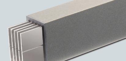
23 SIVACON 8PS system description 3.2 LR system Features The system is distinguished by the following features: Modular system consisting of standard components Combinable with other SIVACON 8PS systems Combinable with non-siemens systems High degree of protection IP68 Suitable for outdoor installation Wide current range (from 400 A to 6150 A) High level of safety Fully insulated Flame retardant Self-extinguishing Resistant to arcing faults Very high short-circuit rating Fire protection Fire resistance class S60 to S90; please enquire about S120 Functional endurance E30 to E120 Maintenance-free Low voltage drop High mechanical strength Resistant to chemicals Conductor material made of copper or aluminium Configuration Manual, 10/2010, A5E
24 SIVACON 8PS system description 3.2 LR system Design The following figure shows the basic design of the LR system: System design Item Description Adapter element LR-LX LR-LD Encapsulated connection element Straight element Junction unit Expansion element Terminal element Fire protection Terminal element to distributor connection Fixing element Tap-off point with outgoing feeder unit Cable feeder unit 22 Configuration Manual, 10/2010, A5E
25 SIVACON 8PS system description 3.2 LR system LR design features Construction types The construction type is dependent on the conductor configuration and on the maximum permissible rated current. Accordingly, the construction types for the LR system are as follows: 4-conductor system Conductor configuration/rated current L1, L2, L3, PEN LRA For maximum rated currents up to 2500 A LRC For maximum rated currents up to 3200 A L1, L2, L3, PEN LRA For maximum rated currents from 3200 A to 4600 A LRC For maximum rated currents from 4000 A to 6150 A Configuration Manual, 10/2010, A5E
26 SIVACON 8PS system description 3.2 LR system 5-conductor system Conductor configuration/rated current L1, L2, L3, N, PE LRA For maximum rated currents up to 2500 A LRC For maximum rated currents up to 3200 A L1, L2, L3, N, PE LRA For maximum rated currents from 3200 A to 4600 A LRC For maximum rated currents from 4000 A to 6150 A Sizes The LR system is available in 10 different sizes. The size is determined by the maximum permissible rated current. Table 3-1 Aluminium system Ie [A] Size Width [mm] Height [mm] 4-conductor system 5-conductor system 4-conductor system 400 LRA LRA LRA LRA LRA LRA LRA LRA LRA LRA LRA LRA Configuration Manual, 10/2010, A5E
27 SIVACON 8PS system description 3.2 LR system Table 3-2 Copper system Ie [A] Size Width [mm] Height [mm] 4-conductor system 5-conductor system 630 LRC LRC LRC LRC LRC LRC LRC LRC LRC LRC LRC LRC Conductor material LRA: Copper-coated aluminium is used exclusively as the conductor material. LRC: Electrolyte copper is used exclusively as the conductor material. The printed circuit boards are rectangular and rounded at the edges. Insulation material The LR system is an encapsulated busbar trunking system. An insulating layer of epoxy resin envelopes the conductors of the LR system. Connection system The electromechanical connection of the individual busbar elements is established using socalled monoblocs. This connection system ensures that only busbar trunking units of an identical size and conductor configuration can be connected to each other. The connection points of the LR system must be encapsulated to achieve the enhanced degree of protection IP68. You require the following accessories for this purpose: Configuration Manual, 10/2010, A5E
28 SIVACON 8PS system description 3.2 LR system Monobloc accessories Casting mould Demoulding agent Cast resin mix Purpose, quantities, definitions Moulding for the cast resin mix Number: one casting mould set is included up to and including 4 monoblocs, i.e. 1 casting mould set is included for every 4 monoblocs. Type definition: BK-S determines the type of the casting mould on the basis of the bar layout in the configuration drawing. The demoulding agent is applied on the inner side of the casting mould. Thus, you ensure that the casting moulds can be reused after hardening of the cast resin mix. Demoulding agent for each connection system: LRA(C)01 to LRA(C)03..: 1 can for 30 busbar connections up to 1000 A Cu/800 A Al LRA(C)04 to LRA(C)06..: 1 can for 25 busbar connections up to 1700 A Cu/1400 A Al LRA(C)07 to LRA(C)09..: 1 can for 20 busbar connections up to 3150 A Cu/2500 A Al LRA(C)27 to LRA(C)29..: 1 can for 15 busbar connections up to 6300 A Cu/5000 A Al The cast resin mix consists of the same material that is used to insulate the busbar elements. Table 3-3 Amount of cast resin for connections Busbar type AL/CU Amount of cast resin for straight connections 4-conductor 5-conductor Buckets LRA/C LRA/C LRA/C LRA/C LRA/C LRA/C LRA/C LRA/C LRA/C LRA/C Buckets Specified volumes include a 5-10% reserve. 26 Configuration Manual, 10/2010, A5E
29 SIVACON 8PS system description 3.2 LR system Table 3-4 Amount of demoulding agent: LRA/C For 1 to 25 connections 1 x 0.5 litres LRA/C For 1 to 20 connections 1 x 0.5 litres LRA/C For 1 to 15 connections 1 x 0.5 litres LRA/C For 1 to 10 connections 1 x 0.5 litres LR connection elements The connection elements for the LR system are referred to as monoblocs. Design The construction type and size of the monoblocs are dependent on the system used. Three construction types are available: 1-bolt monobloc (for 4 and 5-conductor systems) 2-bolt monobloc (for 4 and 5-conductor systems) 4-bolt monobloc (for double busbar trunking systems with 4 and 5 conductors) Design Designation Construction type example 2-bolt monobloc (for 4-conductor systems) Configuration Manual, 10/2010, A5E
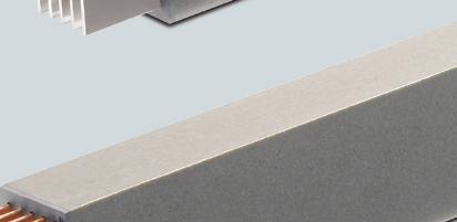
30 SIVACON 8PS system description 3.2 LR system Straight LR elements The following elements are grouped under the term "straight elements": Straight busbar elements Expansion elements Adapter elements LRA-LXA/LRC-LXC/LRA-LDA/LRC-LDC Phase transition units Design and tasks of the straight busbar elements Design Designation Task Straight busbar element Power conveyance along straight runs Unrestricted flat or upright mounting Dimensions of 0.3 m to 3.0 m selectable in lengths that vary by 0.01 m Expansion compensation Compensation of length expansion of the system elements due to heat Unrestricted flat or upright mounting Standard length: 1.0 m 28 Configuration Manual, 10/2010, A5E
31 SIVACON 8PS system description 3.2 LR system Design Designation Task Adapter elements LRA-LDA/LRC-LDC/LRA-L XA/LRC-LXC Transition from LR system to LXA/LXC (LDA/LDC) system Unrestricted flat or upright mounting Standard length: 0.6 m (1.0 m) Connection to SIVACON 8PS/8PT via LX (LD) system Phase transition unit Compensation of line voltage drops in individual conductors Exchange of individual phases LR junction units The following elements are grouped under the term junction units: Elbow (dihedral elbow) Z-element left/right (double dihedral elbow) Knee (flat elbow) Z-element front/rear (flat double elbow) Knee offset (flat/dihedral double elbow) T-element Task Junction units serve to adapt the layout to construction conditions. Configuration Manual, 10/2010, A5E
32 SIVACON 8PS system description 3.2 LR system Design Design Designation Elbow (dihedral elbow) Z-element left/right (double dihedral elbow) Knee (flat elbow) Z-element front/rear (flat double elbow) 30 Configuration Manual, 10/2010, A5E
33 SIVACON 8PS system description 3.2 LR system Design Designation Knee offset (flat/dihedral double elbow) T-element LR terminal elements The following elements are grouped under the term terminal elements: Vertical terminal elements Horizontal terminal elements Cable feeder units Tasks The tasks of the terminal elements are: To connect transformers or distribution boards to the LR system To provide horizontal or vertical busbar trunking systems with current Configuration Manual, 10/2010, A5E
34 SIVACON 8PS system description 3.2 LR system Design of vertical terminal elements Design Designation TO, TO-F terminal element TJ-F terminal element TG-F terminal element TM-F terminal element 32 Configuration Manual, 10/2010, A5E
35 SIVACON 8PS system description 3.2 LR system Design Designation TK-F terminal element TX-F terminal element Configuration Manual, 10/2010, A5E
36 SIVACON 8PS system description 3.2 LR system Design of horizontal terminal elements Design Designation Horizontal TC, TC-F terminal element Horizontal TD-F terminal element Horizontal TE-F terminal element 34 Configuration Manual, 10/2010, A5E
37 SIVACON 8PS system description 3.2 LR system Design of cable feeder unit Design Designation KE cable feeder unit The scope of the cable feeder unit includes: Terminal element, left illustration Casting mould, not illustrated Cast resin mix, not illustrated The cable connection is completely encapsulated during installation LR outgoing feeder points The following elements are grouped under the term outgoing feeder points: Outgoing feeder unit Tap-off unit Configuration Manual, 10/2010, A5E
38 SIVACON 8PS system description 3.2 LR system Design and task Design Designation Task Outgoing feeder unit Provides an encapsulated interface to tap off current up to 630 A Tap-off unit Integration of a power switch-disconnector or customised equipment features 36 Configuration Manual, 10/2010, A5E
39 SIVACON 8PS system description 3.2 LR system LR fire protection and functional endurance Fire protection The LR system covers the requirements of fire resistance ratings S60 to S120 in compliance with EN The LR system features type-tested fire protection that meets the requirements for the fire resistance ratings. For details, see the section entitled "Structural measures" in the chapter entitled Configuring fire protection (Page 96). Please enquire with the product area for details of fire protection versions in compliance with DIN Functional endurance During a fire the electrical systems must retain their functional capability for a defined period of time. "Promatect 200" panels are required for functional endurance classes E30, E60, E90 and E120 of the system. The general test certificate of the construction supervisory authority 1) (abp) applies to production and application of ducts made of "Promatect 200" panels with busbar trunking systems belonging to the "LRC/LRA" type series and the functional endurance class E120 in compliance or accordance with DIN : The functional endurance class E120 can only be issued in accordance with DIN : because only the three functional endurance classes E30, E60 and E90 exist according to DIN : : ) Can be provided on request in product management LR system accessories The following elements are grouped under the term accessories: Casting mould Cast resin mix with curing agent Demoulding agent Transformer connection set Mixer Tool set Torque wrench Fixing sets Configuration Manual, 10/2010, A5E
40 SIVACON 8PS system description 3.2 LR system Design and task Design Designation Task Vertical casting mould Curing and setting container for the cast resin mix Applicable Vertical Horizontal Horizontal casting mould, edgewise busbars Horizontal casting mould, flat busbars Cast resin mix Insulation of the connection point Ensuring the high degree of protection IP68 Demoulding agent Casting mould pre-treatment Prerequisite for dismantling the casting mould 38 Configuration Manual, 10/2010, A5E
41 SIVACON 8PS system description 3.2 LR system Design Designation Task Transformer connection set Fixing with flexible connection straps Mixer Mixing cast resin mix and curing agent Tool set Preparation of the connection points for encapsulation Cleaning the casting point Torque wrench Tightening the clamping bolts on the monoblocs to a defined torque Configuration Manual, 10/2010, A5E
42 SIVACON 8PS system description 3.2 LR system Design Designation Task Horizontal mounting set Suspension of the system Fixing to Ceilings Walls Guarantees correct support Vertical mounting set, fixed point and slip yoke version Vertical mounting set, slip yoke version with spring elements 40 Configuration Manual, 10/2010, A5E
43 4 4.1 Configuration principles Special aspects when configuring the LR system Sequence of configuration phases Configuration of a SIVACON 8PS LR system is broken down into the following phases: Phase 1: preparation of a bid (after a customer enquiry) Phase 2: preconfiguration Phase 3: detailed configuration Configuration work splitting Contrary to the approach adopted for configuration of other SIVACON 8PS systems, LR systems are configured together with BKS. This results in the following work splitting during the configuration process: Siemens Sales takes care of preparation of a bid and preconfiguration BKS takes care of detailed configuration Phase 1: Preparation of a bid Bid preparation The QuotationManager software tool (parts list-based) is used for bid preparation. Data and information stored in the software are accessed during preparation of a bid. This simplifies bid preparation. Components of a bid A bid contains the configured system's technical data and a description of its volume. Configuration Manual, 10/2010, A5E
44 4.1 Configuration principles Necessary technical data/information A bid must contain the following technical data: Rated current I e Rated insulation voltage Vi Rated operational voltage U e Short-circuit resistance I cw Short-circuit resistance I pk Degree of protection Network configuration (4/5-conductor) Conductor material (Al or Cu) Maximum permissible voltage drop (please enquire) Additional information (e.g.: fire protection and functional endurance) Ambient conditions(temperature / relative humidity, etc.) Note Refer to the technical data for the derating conversion factors. See also Technical data Derating (Page 154) Necessary information on description of the volume The following information describes the volume and must be included in the bid: Parts list Sketch of the busbar layout Construction drawing Text description (bill of quantities) 42 Configuration Manual, 10/2010, A5E
45 4.1 Configuration principles Phase 2: Preconfiguration Necessary information During the preconfiguration phase, the following information must be made available and communicated to BKS: Project number Technical data in conformity with the bid Busbar layout (determine with BusbarPlan) Detailed transformer data Detailed distribution box data Hole patterns Phase position Cross-sections of connecting cables Wall positions Positions of tap-off points Implementation data QuotationManager bid Additional information about miscellaneous special aspects Ambient conditions(temperature/chemical conditions, etc.) Rated current, adjusted to the ambient temperatures (derating) Note Refer to the technical data for the derating conversion factors. See also Technical data Derating (Page 154) Configuration Manual, 10/2010, A5E
46 4.1 Configuration principles Phase 3: Detailed configuration Coordination with BKS BKS takes care of detailed configuration. The following points must be coordinated with BKS: Project number Bid number Binding ordering parts list with items Busbar layout with items Fixing elements and their positions Expansion compensation and fixed points Transformer connection details, including copper plating of the terminal lugs Distribution board connection and its position Outgoing feeder points and tap-off units, if necessary Nature and quantity of necessary accessories Single part drawings, if necessary Use of phase transition units 44 Configuration Manual, 10/2010, A5E
47 4.2 Selection and type definition with LR system 4.2 Selection and type definition with LR system Type key of the LR system Overview The illustrated type key serves to determine the order types of the system elements: Type key Configuration Manual, 10/2010, A5E
48 4.2 Selection and type definition with LR system Note Order types that cannot be determined with this type key are: Adapter element LRA-LXA/LRC-LXC/LRA-LDA/LRC-LDC Casting moulds Flexible connection straps Bolting sets Fire protection kits Accessories for fixing and assembly 46 Configuration Manual, 10/2010, A5E
49 4.2 Selection and type definition with LR system Additional type keys for fire protection kits Selectable options With the fire protection kits, busbar elements achieve the fire protection class S90 or S120. The fire protection kits are used for wall or ceiling penetrations. You order the appropriate fire protection kits for straight busbar elements on the basis of the type keys shown below: Type key for fire protection kit 1) S90 Type key for fire protection kit 1) S120 Configuration Manual, 10/2010, A5E
50 4.2 Selection and type definition with LR system Scope of fire protection kits 1) The fire protection kits contain the following components: Fire protection kit Fire protection class S90 Protective coating Sealing material Fire protection class S120 "Promatect 200" panels Scope of the approval set for Germany: Please enquire 1) Fire protection kits in compliance with the requirements of IEC or EN For the requirements of DIN 4102 (valid for use of fire protection on the German market), you must enquire with the product area for details of the fire protection kits. See also Selection list for LR system fire protection accessories (Page 74) 48 Configuration Manual, 10/2010, A5E
51 4.2 Selection and type definition with LR system Selection list for straight elements LR Selection lists The following selection lists serve to determine the order designations for straight elements. Note For the system elements listed below, monoblocs must be ordered separately! Order designations for straight busbar elements Straight busbar element X [m] Configurable length [m] Order designation 0,5 0, ,50-0,5 1,0 0,51 1,0-1,0 1,5 1, ,50-1,5 2,0 1, ,0-2,0 2,5 2, ,50-2,5 3,0 2, ,0-3,0 The individual lengths can be configured freely in cm increments from 0.3 m to 3.0 m. Straight busbar element, conductor material Cu, size 09, 4-conductor, length = 1.7 m: Entry 1: LRC Straight busbar element, conductor material Cu, size 09, 4-conductor, length = 1.7 m, with fire protection kit S120 Entry 1: Entry 2 LRC LRC S120 Configuration Manual, 10/2010, A5E
52 4.2 Selection and type definition with LR system Order designations for expansion elements Expansion element X Order designation [m] 1,0 -D Example: expansion compensation, conductor material Cu, size 09, 4-conductor: Entry 1: LRC D Order designations for LRA -LXA adapter elements for 4-conductor systems Adapter element LRA - LXA X [m] Rated current Ie [A] system transition 0,6 Defined LRA system Order designation Connectable LXA system 800 LRA LXA LRA LXA LRA LXA LRA LXA LRA LXA LRA LXA LRA LXA LRA LXA LRA LXA LRA LXA Configuration Manual, 10/2010, A5E
53 4.2 Selection and type definition with LR system Order designation for LRA - LXA adapter elements for 5-conductor systems Adapter element LRA - LXA X [m] Rated current Ie [A] system transition 0,6 Defined LRA system Order designation Connectable LXA system 800 LRA LXA LRA LXA LRA LXA LRA LXA LRA LXA LRA LXA LRA LXA LRA LXA LRA LXA LRA LXA1051 Order designation for LRA - LXA adapter elements for (5-conductor system) When selecting adapter elements, you only need one entry in the ordering list in addition to the order designation; see the following example: Adapter element, conductor material Al, size 05, 5-conductor Entry: LRA LXA0451 Order designations for LRC - LXC adapter elements for 4-conductor systems Adapter element LRC - LXC X [m] Rated current Ie [A] system transition 0,6 Defined LRC system Order designation Connectable LXC system 1000 LRC LXC LRC LXC LRC LXC LRC LXC LRC LXC LRC LXC LRC LXC LRC LXC LRC LXC LRC LXC0941 Configuration Manual, 10/2010, A5E
54 4.2 Selection and type definition with LR system Order designation for LRC - LXC adapter elements for 5-conductor systems Adapter element LRC - LXC X [m] Rated current Ie [A] system transition 0,6 Defined LRC system Order designation Connectable LXC system 1000 LRC LXC LRC LXC LRC LXC LRC LXC LRC LXC LRC LXC LRC LXC LRC LXC LRC LXC LRC LXC0951 Order designation for LRC-LXC adapter elements for (4-conductor system) When selecting adapter elements, you only need one entry in the ordering list in addition to the order designation; see the following example: adapter element, conductor material Cu, size 04, 4-conductor: Entry: LRC LXC0241 Order designations for LRA-LDA adapter elements for 4-conductor systems Adapter element LRA - LDA X [m] Rated current Ie [A] system transition 1,0 Defined LRA system Order designation Connectable LDA system 1000 LRA LDA LRA LDA LRA LDA LRA LDA LRA LDA LRA LDA LRA LDA LRA LDA LRA LDA LRA LDA LRA LDA LRA LDA Configuration Manual, 10/2010, A5E
55 4.2 Selection and type definition with LR system Order designations for LRA-LDA adapter elements for 5-conductor systems Adapter element LRA - LDA X [m] Rated current Ie [A] system transition 1,0 Defined LRA system Order designation Connectable LDA system 1000 LRA LDA LRA LDA LRA LDA LRA LDA LRA LDA LRA LDA LRA LDA LRA LDA LRA LDA LRA LDA LRA LDA LRA LDA8610 Order designation for LRA - LDA adapter elements for (5-conductor system) When selecting adapter elements, you only need one entry in the ordering list in addition to the order designation; see the following example: Adapter element, conductor material Al, size 05, 5-conductor Entry: LRA LDA2620 Order designations for LRC-LDC adapter elements for 4-conductor systems Adapter element LRC - LDC X [m] Rated current Ie [A] system transition 1,0 Defined LRC system Order designation Connectable LDC system 2000 LRC LDC LRC LDC LRC LDC LRC LDC LRC LDC LRC LDC LRC LDC LRC LDC8410 Configuration Manual, 10/2010, A5E
56 4.2 Selection and type definition with LR system Order designations for LRC-LDC adapter elements for 5-conductor systems Adapter element LRC - LDC X [m] Rated current Ie [A] system transition 0,6 Defined LRC system Order designation Connectable LDC system 2000 LRC LDC LRC LDC LRC LDC LRC LDC LRC LDC LRC LDC LRC LDC LRC LDC8610 Order designation for LRC-LDC adapter elements for (5-conductor system) When selecting adapter elements, you only need one entry in the ordering list in addition to the order designation; see the following example: adapter element, conductor material Cu, size 07, 5-conductor Entry: LRC LDC2620 Order designations for phase transition units Phase transition unit X [m] Order designation 0,5-0,5 -P 1,0-1,0 -P 1,5-1,5 -P 2,0-2,0 -P 2,5-2,5 -P 3,0-3,0 -P 54 Configuration Manual, 10/2010, A5E
57 4.2 Selection and type definition with LR system Example order designation for phase transition units When selecting phase transition units, you need two entries in the ordering list in addition to the order designation; see the following example: Straight busbar element, conductor material Cu, size 03, 4-conductor, standard length = 1.0 m: phase transition unit version Entry 1: Entry 2: LRC LRC P Order designations for outgoing feeder units Straight busbar element X [m] Configurable length [m] Order designation 0,5 0,3... 0,5-0,5 LR-AD 1,0 0,5 1,0-1,0 LR-AD 1,5 1,0... 1,5-1,5 LR-AD 2,0 1,5... 2,0-2,0 LR-AD 2,5 2,0... 2,5-2,5 LR-AD 3,0 2,5... 3,0-3,0 LR-AD The individual lengths can be configured freely in cm increments from 0.3 m to 3.0 m. Example order designation for outgoing feeder units When selecting outgoing feeder units, you need two entries in the ordering list in addition to the order designation; see the following example: Straight busbar element, conductor material Cu, size 03, 4-conductor, standard length = 1.0 m: Outgoing feeder unit version Entry 1: Entry 2: LRC LR-AD Configuration Manual, 10/2010, A5E
58 4.2 Selection and type definition with LR system Selection list for LR junction units Selection lists The following selection lists serve to determine the order designations for junction units. Note For the system elements listed below, monoblocs must be ordered separately! Order designations for elbow (dihedral elbow) Elbow (dihedral elbow) Max. total length X + Y [m] Variable leg lengths X [m] Y [m] Order designation For LRA(C) E from LR...01 to LR E-1.0 from LR...01 to LR E-1.5 from LR...01 to LR...29 The individual leg lengths can be configured freely in cm increments from 0.31 m to 1.2 m. (order designations -E, -E-1.0 and -E-1.5) Both leg lengths together must not exceed the chosen maximum overall length. 56 Configuration Manual, 10/2010, A5E
59 4.2 Selection and type definition with LR system Order designations for Z-element left/right (double dihedral elbow) Z-element left/right (double dihedral elbow) LRA(C) system For sizes LR LR..29 X [m] Y [m] Z [m] Order designation ZE The leg length Z can be configured freely in cm increments from 0.01 m to 0.7 m. Order designations for knee (flat elbow) Knee (flat elbow) LRA(C) system Total length Variable leg lengths X + Y [m] X [m] Y [m] Order designation LR...01 to LR K LR to LR K-1.0 LR to LR LR to LR K-1.5 LR to LR The individual leg lengths can be configured freely in cm increments within the following limits: In the case of single systems, from 0.35 m to 1.15 m In the case of double systems, from 0.5 m to 1 m Both leg lengths together must not exceed the chosen overall length. Configuration Manual, 10/2010, A5E
60 4.2 Selection and type definition with LR system Order designations for Z-element front/rear (flat double elbow) Z-element front/rear (flat double elbow) LRA(C) system For sizes LR...01 to LR...09 For sizes LR...27 to LR...29 X [m] Y [m] Z [m] Order designation ZK ZK Order designations for knee offset (flat/dihedral double elbow) (4-conductor system) Knee offset (flat/dihedral double elbow) LRA(C) system LR LR LR X [m] Y [m] Z [m] LR LR LR LR LR LR LR LR LR Order designation - XL 58 Configuration Manual, 10/2010, A5E
61 4.2 Selection and type definition with LR system Order designations for knee offset (flat/dihedral double elbow) (5-conductor system) Knee offset (flat/dihedral double elbow) LRA(C) system LR LR LR X [m] Y [m] Z [m] LR LR LR LR LR LR LR LR LR Order designation - XL Order designations for knee offset (flat/dihedral double elbow) (4-conductor system) Knee offset (flat/dihedral double elbow) LRA(C) system LR LR LR X [m] Y [m] Z [m] LR LR LR LR LR LR LR LR LR Order designation - XR Configuration Manual, 10/2010, A5E
62 4.2 Selection and type definition with LR system Order designations for knee offset (flat/dihedral double elbow) (5-conductor system) Knee offset (flat/dihedral double elbow) LRA(C) system LR LR LR X [m] Y [m] Z m] LR LR LR LR LR LR LR LR LR Order designation - XR Order designations for T-elements T-element LRA(C) system X [m] Y [m] Z [m] Order designation For sizes LR...01 to LR TV For sizes LR...27 to LR...29 For sizes LR...01 to LR TV TV-2.0 For sizes LR...27 to LR TV Configuration Manual, 10/2010, A5E
63 4.2 Selection and type definition with LR system Selection list for LR terminal elements Selection lists The following selection lists serve to determine the order designations for terminal elements. Note For the system elements listed below, monoblocs must be ordered separately! Exception: Terminal element for KE cable feeder unit Order designations for terminal elements (vertical connection) Note If required, the specified maximum values for the dimension X can be extended in increments of 0.1 m. For all terminal elements, you order the extension by making an additional entry in the ordering parts list. The additional entry is based on the following sample: Example of TO terminal element, conductor material Cu, size 28, 4-conductor, version: extension by X=0.3 m Entry 1: Entry 2: LRC TO-F 3 x LRC ) 1) Example: 3 x LRC corresponds to extension by 3 x 0.1 m! TO terminal element LRA(C) system X [m] Z [m] Order designation 4-conductor conductor TO Configuration Manual, 10/2010, A5E
64 4.2 Selection and type definition with LR system TO-F terminal element LRA(C) system X [m] Z [m] Order designation 4-conductor < TO-F 5-conductor Extension each TJ-F terminal element LRA(C) system X [m] Z [m] Order designation LR...01 to LR...09 < TJ-F LR...27 to < 1.0 LR...29 Extension each TG-F terminal element LRA(C) system X [m] Z [m] Order designation All systems < TG-F Extension each Configuration Manual, 10/2010, A5E
65 4.2 Selection and type definition with LR system TM-F terminal element LRA(C) system X [m] Z [m] Order designation LR.01 - LR.09 < TM-F LR.27 - LR Extension each TK-F terminal element LRA(C) system X [m] Z [m] Order designation LR.01 - LR.09 < TK-F LR.27 - LR.29 < Extension each Configuration Manual, 10/2010, A5E
66 4.2 Selection and type definition with LR system TX-F terminal element LRA(C) system X [m] Z [m] Order designation LR.01 to LR...09 < TX-F LR...27 to LR...29 < Extension each Example of TO-F terminal element, conductor material Cu, size 05, 5-conductor, version: extension by X=0.4 m Entry 1: Entry 2: LRC TO-F 4 x LRC ) 2) Example: 4 x LRC corresponds to extension by 4 x 0.1 m! Order designations for terminal elements (horizontal connection) TC terminal element LRA(C) system X [m] Z [m] Order designation 4-conductor conductor TC 64 Configuration Manual, 10/2010, A5E
67 4.2 Selection and type definition with LR system TC-F terminal element LRA(C) system X [m] Z [m] Order designation 4-conductor 5-conductor < TC-F Extension each TD-F terminal element LRA(C) system X [m] Z [m] Order designation All systems < TD-F Extension each TE-F terminal element LRA(C) system X [m] Z [m] Order designation LR...01 to < TE-F LR...09 LR...27 to LR...29 < 1.0 Extension each Configuration Manual, 10/2010, A5E
68 4.2 Selection and type definition with LR system Note Terminal elements for horizontal connections can be extended in increments of 0.1 m. Two entries must be made for extensions. See the following example Example of TC-F terminal element, conductor material Cu, size 03, 4-conductor, version: extension by X=0.3 m Entry 1: Entry 2: LRC TC-F 3 x LRC ) Example: 4 x LRC corresponds to extension by 3 x 0.1 m! Length selection for cable feeder unit KE cable feeder unit LRA(C) system X [m] 4-conductor conductor 0.55 X1, X2, X3 [m] Y [m] Z [m] Z1 [m] Order designation KE Example of cable feeder unit KE, conductor material Cu, size 09, 4-conductor Entry 1: LRC KE Note Cable feeder unit -KE is delivered from the factory inclusive of the casting mould! 66 Configuration Manual, 10/2010, A5E
69 4.2 Selection and type definition with LR system Selection list for LR accessories Selection lists The following selection lists serve to determine the order designations for accessories: Order designations for horizontal fixing sets Illustration: horizontal fixing Size Order designation Flat On its edge Flat On its edge LR03-BHF LR03-BHH 04 LR04-8-BHF LR04-8-BHH 05 LR05-0-BHF LR05-0-BHH 06 LR06-2-BHF LR06-2-BHH 07 LR07-8-BHF LR07-8-BHH 08 LR08-0-BHF LR08-0-BHH 09 LR09-2-BHF LR09-2-BHH 27 LR27-8-BHF LR27-8-BHH 28 LR28-0-BHF LR28-0-BHH 29 LR29-2-BHF LR29-2-BHH Example order designation: Horizontal fixing, on its edge and flat, sizes 01/02/03: Entry 1: LR03-BHH LR03-BHF Example order designation: Horizontal fixing, on its edge and flat, sizes 09: Entry 1: LR09-2-BHF Configuration Manual, 10/2010, A5E
70 4.2 Selection and type definition with LR system View Designation Size Order designation Horizontal fixing, LR-BHW1 wall LR-BHW2 Horizontal fixing, floor Please enquire Example order designation: Horizontal fixing, wall, size 09: Entry 1: LR-BHW1 68 Configuration Manual, 10/2010, A5E
71 4.2 Selection and type definition with LR system Order designations for vertical fixing sets View Designation Application/scope Size Order designation Fixed point for vertical Fixing the busbar run LR03-BF installation LR...-BF* Fixing the busbar run LR03-BFD on a ceiling LR...-BFD* Vertical fixing, sliding Sliding fixing (without LR03-BG spring elements) LR...-BG* Vertical fixing, ceiling Vertical fixing, wall Fixing with load bearing (with spring elements) Fixing with load bearing (with spring elements) LRA(C)03-BVD LRA(C)...-BVD* LRA(C)03-BVW LRA(C)...-BVW* * The size and the conductor configuration are specified. Note You order the applicable fixing set for size LRC05 by using the order designation 06. Example order designation: Conductor material Al, vertical ceiling fixing, size 06, 4-conductor Entry 1: LRA BVD Configuration Manual, 10/2010, A5E
72 4.2 Selection and type definition with LR system Order designations for assembly accessories View Designation Application/scope Order designation Monobloc Monobloc 1) Cast resin mix LRA(C)...-KB Mixer 750 W/230 V LR-MIX W/230 V LR-MIX2 Cast resin mix 1 tub with: solid (12 kg), can of epoxy resin (1.8 kg), curing agent (0.6 kg) LR-RES Torque wrench Tightening the monobloc clamping bolts LR-DR Tool set Grinding stone, aluminium tape for sealing, spray bottle for demoulding agent, fibre fleece for surface cleaning, spatula, 19 cm ring/open-ended spanner LR-WS 70 Configuration Manual, 10/2010, A5E
73 4.2 Selection and type definition with LR system View Designation Application/scope Order designation Demoulding agent 0.5 kg LR-SEP 1) Casting mould must be ordered separately. 2) Enter the bid number! Transformer adapter Electroplated, Please enquire box Height = 0.15 m Special item LR-SOND 2) Spare part LR-ET/ Selection list for transformer connection Components You need the following components to connect a transformer to the LRA(C) system: Flexible connection straps Bolting set Note Connection straps and bolting sets are ordered separately. Configuration Manual, 10/2010, A5E
74 4.2 Selection and type definition with LR system Selection of flexible connection straps The number of required connection straps depends on the rated current. Select the ordering types on the basis of the following tables: View Designation Description Order designation Flexible connection straps Pressure-welded copper expansion strips with tin-plated contact faces LR-FLEX- 1) 1) The dimensions of the terminal lugs are added to the order designation LR-Flex- to arrive at the ordering type. Ordering type 2) Cross-section Weight Rated current Ie [A] [mm 2 ] [kg] 1-layer 2-layer 3-layer LR-FLEX-50X06X LR-FLEX-50X08X LR-FLEX-50X10X LR-FLEX-50X12X LR-FLEX-60X06X LR-FLEX-60X08X LR-FLEX-60X10X LR-FLEX-60X12X LR-FLEX-80X06X Configuration Manual, 10/2010, A5E
75 4.2 Selection and type definition with LR system Ordering type 2) Cross-section Weight Rated current Ie [A] [mm 2 ] [kg] 1-layer 2-layer 3-layer LR-FLEX-80X08X LR-FLEX-80X10X LR-FLEX-80X12X LR-FLEX-100X06X LR-FLEX-100X08X LR-FLEX-100X10X LR-FLEX-100X12X LR-FLEX-120X10X LR-FLEX-120X12X ) Ordering type with details of the terminal lugs' dimensions! Selection of bolting sets Note The quantity and type of required bolting sets depend on each specific project. Required bolting sets are therefore selected by BKS during the detailed configuration phase. The following table lists the available bolting sets: Designation Description Ordering type Bolting set M12 thread Screw length [mm] All bolting set versions cost the same. The number of required bolting sets depends on the hole pattern. LR-SCREW35M12 LR-SCREW40M12 LR-SCREW45M12 LR-SCREW50M12 LR-SCREW55M12 LR-SCREW60M12 LR-SCREW65M12 LR-SCREW70M12 LR-SCREW80M12 LR-SCREW90M12 LR-SCREW100M12 LR-SCREW110M12 LR-SCREW120M12 LR-SCREW130M12 LR-SCREW140M12 Configuration Manual, 10/2010, A5E
76 4.2 Selection and type definition with LR system Selection list for LR system fire protection accessories Selection list The following fire protection accessories are available in conformity with the differing fire resistance classes 1). Accessories Note Fire resistance class 1) Ordering addresses S60 S90 S120 1 Fire protection mortar Promat Promastop Type S, Art. No Fire protection filling compound Beele Actifoam 3 Sealing compound Beele FIWA 4 Fire protection kit 1) S90 5 Fire protection kit 1) LRA(C)...-S120 6 Approval set 1) (X) (X) (X) Promat GmbH Scheifenkamp 16, D Ratingen Telephone: Fax: mail@promat.de ( ( Alternative to fire protection mortar Sealing gaps after using Actifoam (X) (X) (X) (X) (X) (X) Schulte Strathaus GmbH & Co. KG Runtestrasse 42, D Werl Telephone: +49 (0) / Fax: +49 (0) 29 22/ info@schulte-strathaus.de ( ( LRA(C) X Siemens Sales Ordering type: LRA(C)09-S90 LRA(C) X Siemens Sales Ordering type: LRA(C)29-S90 Including panels, X Siemens Sales type "Promatect 200" Ordering type: LRA(C)...-S120 Required for Germany! X X X Please enquire Note Ordering process The items 1 to 3 are processed locally. They are needed only to seal the wall opening. Order fire protection accessories directly via the specified ordering addresses. There, you will obtain all information about: Container sizes Prices Processing notes 74 Configuration Manual, 10/2010, A5E
77 4.2 Selection and type definition with LR system See also Additional type keys for fire protection kits (Page 47) 1) Please enquire about the version for Germany in compliance with the stipulations of the responsible construction authority. Configuration Manual, 10/2010, A5E
78 4.2 Selection and type definition with LR system Type keys of the casting moulds for the LR system Overview The illustrated type key serves to determine the order types of the casting moulds: Type key 76 Configuration Manual, 10/2010, A5E
79 4.2 Selection and type definition with LR system Note Available LRA(C)01 - LRA(C)03 build-up layers Regardless of the conductor configuration, the LRA(C)01 to LRA(C)03 systems have a square cross-section. Note that only the build-up layer D is available for these systems Selection list for LR casting moulds Selection lists The following selection list serves to determine the types of casting moulds: Determining the types of casting moulds Casting moulds System size Size/type LR 01 8/ / / /13-N 05 13/17-N 06 16/19-N 07 17/20-N 08 20/25-N 09 24/31-N 27 34/40-N 28 40/50-N 29 49/63-N Configuration Manual, 10/2010, A5E
80 4.3 Configuring the LR busbar run Casting mould order designation When selecting casting moulds, you only need one entry in the ordering list in addition to the designation of the order type; see the following example: Example LRC0441-8, casting mould, horizontal, flat Entry: LR-4FF11/13-N 4.3 Configuring the LR busbar run Configuration The following must be configured in connection with the busbar run: Distances from structures Minimum distances for horizontal installation Minimum distances for vertical installation Wall and ceiling openings Busbar end Distances from structures With regard to the layout of LR system busbars, appropriate distances from structures must be observed. Distances from structures Item Description 0.5 m min Monobloc centre LR system Tap-off point at top Tap-off point at bottom Additional space requirement for the tap-off unit 78 Configuration Manual, 10/2010, A5E
81 4.3 Configuring the LR busbar run Minimum distances for horizontal installation Minimum distances from the wall and ceiling must be observed for establishment of the electromechanical connection and the connection point. Minimum distances Item Description 1 2 Wmin = 0.1 m Dmin = 0.1 m Minimum distances for vertical installation Minimum distances from the wall and ceiling must be observed for establishment of the electromechanical connection and the connection point. Minimum distances Item Description LR system: Wmin = 0.1 m 1 2 Front with tap-off points, if necessary: Wzmin = 0.15 m 3 Vertical fixing Configuration Manual, 10/2010, A5E
82 4.3 Configuring the LR busbar run Wall and ceiling penetrations Appropriately large openings must be provided in masonry for the wall and ceiling penetration points of the LR system. Wall penetration Ceiling penetration Item Description a b 1 Wall opening System width +100 mm System height +100 mm Busbar end Note Contrary to the other SIVACON 8PS systems, there is no end flange in the LR system. The last busbar element in the layout is cast at the manufacturer's specifically for the project or order. 80 Configuration Manual, 10/2010, A5E
83 4.4 Configuring LR connections 4.4 Configuring LR connections Configuration The busbar elements are positioned so that there is a distance of approximately 30 mm between the busbar ends. Distance between two elements Item Description 1 Busbar element Additional space requirement must be planned for vertical installation in a flat position with respect to the wall. This is necessary because the monobloc (approximate system height) has to be fitted from the side. Space requirement for vertical installation Item Description (W1min) H 1 W1min = 0.1 m System height Monobloc Configuration Manual, 10/2010, A5E
84 4.4 Configuring LR connections Connecting The monobloc is then inserted and fitted. The monobloc's bolt features a shear-off head that shears off when the required torque is reached. If the shear-off head has already been torn off, the terminal must be tightened to a 3 x torque. (LR LR.03: 40 Nm and LR LR.06: 84 Nm). Mounting position of a monobloc Item Description 1 2 Busbar elements Monobloc 82 Configuration Manual, 10/2010, A5E
85 4.4 Configuring LR connections Casting Note Before the casting mould is fitted, its inside must be greased with the demoulding agent (LR- SEP). This is imperative to be able to detach and reuse the casting moulds again after setting. The casting mould is fitted after fitting of the monobloc. Casting mould installation position Item Description 1 2 Busbar elements Casting mould The prepared cast resin mix can be poured in once the casting mould has been fitted. The cast resin mix requires a setting time of 7-8 h under normal ambient conditions. The cast resin mix is supplied in a tub with the single components (12 kg solids, 1.8 kg can of resin and 0.6 kg curing agent). The cast resin mix must be mixed on the site with an agitator. Configuration Manual, 10/2010, A5E
86 4.4 Configuring LR connections Casting the connection point Item Description 1 2 Busbar elements Cast resin mix After setting, the casting mould must be removed again. The casting mould can be reused. One set of casting moulds can be used for four busbar connections. The following figure shows the dimensions of the encapsulated connection point. Dimensions of an encapsulated connection point Item Description 1 2 Busbar elements Encapsulated connection point 84 Configuration Manual, 10/2010, A5E
87 4.5 Configuring straight LR busbar elements 4.5 Configuring straight LR busbar elements Configuration The configuration dimension for straight busbar elements is always from the monobloc centre to the monobloc centre: Configuration dimensions for straight busbar elements Item Description 1 Monobloc centre 2 Length from monobloc centre to monobloc centre Configuring chosen lengths The configuration dimension for chosen lengths is always from the monobloc centre to the monobloc centre Configuration dimensions for chosen lengths Item Description 1 2 W a Monobloc centre Busbar end Chosen length of busbar element Length with monoblocs Note Configuration dimension: W = a [mm] - 30 mm Configuration Manual, 10/2010, A5E
88 4.6 Configuring LR junction units 4.6 Configuring LR junction units A note in advance The conductors of the LR system are arranged symmetrically to the longitudinal axis. Thanks to the conductor symmetry, the junction units can be used as left or right elbows and as front or rear elbows. This reduces the system's type diversity and configuration complexity. Application methods of junction units Item Description 1 2 Elbow Busbar element Configuration The configuration dimension for junction units is always from the monobloc centre to the monobloc centre. Note This system deviates from the configuration method for the well-known LD, LX or BD2 systems. 86 Configuration Manual, 10/2010, A5E
89 4.6 Configuring LR junction units Configuration dimensions for single elbows Configuration dimensions for double elbows Item Description 1 Monobloc centre Configuration Manual, 10/2010, A5E
90 4.7 Configuring LR terminal elements 4.7 Configuring LR terminal elements Configuration The configuration dimension for terminal elements is always from the monobloc centre to the end of the busbar element. Configuration dimensions for terminal elements Item Description 1 X Z Monobloc centre Length of lug connection zone Height of terminal element Y Distance to monobloc centre The X-dimension of transformer and distribution board terminal elements is defined as a maximum of 0.70 m (1.00 m in the case of double systems). If a large X-dimension should be necessary due to larger lug distances, this is covered by the ordering type LR for every 100 mm of additional length. 88 Configuration Manual, 10/2010, A5E
91 4.7 Configuring LR terminal elements Positioning The terminal element must be positioned as follows above the transformer: Configuration dimensions for determining the position Item Description 1 Transformer connection terminal element Monobloc centre 2 a Dimension data for detailed configuration Connecting The terminal lugs including the hole pattern are dimensioned in relation to each specific order. An additional assembly flange for adaptation to the transformer housing is included for the TO and TC terminal elements Assembly flange for terminal elements Item Description Assembly flange for terminal elements 1 Depending on the system size, a set of flexible straps and screws is available for transformer connection. A set price is available for the bid phase. Within the scope of detailed configuration, during ordering this set is broken down into flexible straps and bolting sets (LR-FLEX*, LR-SCREW*). Configuration Manual, 10/2010, A5E
92 4.8 Configuring LR tap-off points 4.8 Configuring LR tap-off points Configuration If power taps are planned along the busbar layout, the appropriate number and components of the tap-off points must be defined. The maximum permissible rated current of a tap-off point is limited to 630 A. The tap-off point is equipped with a protective device depending on the customer's requirements. The positions and design of the tap-off points in the busbar layout are defined in the detailed configuration phase. 4.9 Configuring LR system transitions Configuration A type-tested connection to the LX or LD system can be implemented for the LR system using an adapter element. Adapter elements for a transition from the LR system to the LX or LD system are available for all LXA/LXC and LDA/LDC system sizes. For use of the LR-LD transition box in the horizontal layout, attention must always be paid to the LD system's standard installation position. This results in edgewise for LD for the horizontal installation position flat for LR for the horizontal installation position Due to expansion of the busbar run in the transition box, it is not possible to use the LR-LD transition box in the vertical busbar run with the standard fastening accessories. If required in special cases, product management must be contacted. Note The dimensions of the LR-LD adapters are specified in accordance with the LR configuration from center of clamp-connection to center of clamp-connection. For the LD configuration, 2 cm must be observed in addition, since the LD metal edge to bolt middle overlaps by 2 cm at the LD bolt side. Note A type-tested connection to the SIVACON 8PV / 8PT and S4 / S8 power distribution boards can also be implemented with the adapter element. The relevant adapter elements are available for all sizes. 90 Configuration Manual, 10/2010, A5E
93 4.10 Configuring the LR expansion compensation 4.10 Configuring the LR expansion compensation Expansion compensation Due to heat dissipation under load, the busbar assembly including the enclosure expand. Length expansion of the busbar assembly depends on: Conductor material of the busbar system Layout of the busbar system (horizontal or vertical) Purpose (power conveyance or distribution) Expansion compensation in practice Expansion compensation is implemented by using a special busbar element with integrated expansion strips. This element absorbs expansion of the busbar run up to the specified maximum busbar run length and must be positioned in conformity with the configuration rules for a horizontal or vertical layout. Within a defined length, expansion compensation can compensate for both tension and compression forces. Configuration cases Three cases must be distinguished during configuration: Configuring horizontal busbar layouts Configuring height changes within horizontal layouts Configuring vertical busbar layouts For preparation of a bid, one expansion compensation element must be calculated for every 35 m 40 m of the total busbar length. Fixed points need not be calculated separately Configuring LR fixed points Fixed points Fixed points are special fixing brackets that permanently fix the busbar element to the fixing material available on site. They therefore ensure expansion compensation in a defined direction. A distinction is made between horizontal and vertical installation fixed points (see selection and ordering data). Configuration Manual, 10/2010, A5E
94 4.12 Configuring LR fixing elements Attachment of fixed points Attachment of a fixed point is necessary on the following busbar components: Distribution board terminal connection elements Cable feeder units (KE) Transformer terminal connection elements Straight busbar elements and junction units depending on the length and course of the busbar run (defined during detailed configuration). Expansion compensation elements and fixed points are configured within the scope of detailed configuration by BKS Configuring LR fixing elements Configuration Generally a maximum permissible fixing distance of 1.5 m between 2 fixing points should be observed. On busbar elements with a length of 2 m to 3 m the use of two fixing elements is recommended. Configuring fixing points Item Description 1 2 Monobloc centre Fixing point The fixing brackets should be placed vertically and horizontally every 1.5 m. The different weights of single and double systems should be considered when choosing the fixing brackets. The fixing brackets feature different C-profiles due to the different system weights. Minimum fixing methods for horizontal installation Three possibilities are provided here: Ceiling: suspended installation Wall: supported installation Floor: elevated installation 92 Configuration Manual, 10/2010, A5E
95 4.12 Configuring LR fixing elements Ceiling fixing example: suspended installation Description 1 Threaded rods 2 C-profiles 3 Dowels (suspension up to 1.0 m under the ceiling), part of the fixing sets LR..-BHH / LR..-BHF Note on the fixing sets LR..-BHH / LR..-BHF. Components are: 2 x M10 threaded rods 2 C-profiles 4 lock nuts with spring washers Wall fixing example: supported installation Description 4-conductor system: LR-BHW1 (illustrated on left) Double system LR-BHW2 (illustrated on right) mounted on a support. Configuration Manual, 10/2010, A5E
96 4.12 Configuring LR fixing elements Floor fixing example: elevated installation Description Double system elevated on the floor (available on request) Possible fixing methods for vertical installation Two possibilities are provided here: Fixing with spring clips Fixing with slip yokes Fixing with fixed point brackets 94 Configuration Manual, 10/2010, A5E
97 4.12 Configuring LR fixing elements Vertical installation fixing examples Description Fixing with spring clips (for weight support) [Type: LR -BVD(W)] Fixing with slip yokes or fixed point brackets [Types: LR -BF(G)(VD)(VW)] Note The spring clips or slip yokes are configured within the scope of detailed configuration by BKS. For the bid, one spring clip and one slip yoke must be planned for every 1.5 m. Configuration Manual, 10/2010, A5E
98 4.13 Configuring fire protection 4.13 Configuring fire protection Fire protection requirements The LR system meets the requirements of the following standards: Fire protection to EN Fire resistance classes S60 to S120 in compliance with EN and DIN for use on the German market. The German state authorities have also stipulated that buildings must be designed so that: "[...] "[...] "The development and spread of fire must be prevented and the rescue of persons and animals as well as fire fighting must be possible". Thus, the requirement is that neither fire nor smoke may cross from one fire sector to another. Note A general construction permit from the German Institute for Construction Technology (Deutsches Institut für Bautechnik) in Berlin (DIBt) is currently not available. Enquire with the product area. Special aspects of LR fire protection By default, LR fire protection fulfils the requirements of fire resistance classes S60, S90 and S120 in compliance with EN Categorisation according to the relevant fire resistance class applies to all kinds of buildings, including high-rise buildings. For use of LR fire protection in compliance with DIN for the German market, you must clarify the fire protection version in advance in the product area. 96 Configuration Manual, 10/2010, A5E
99 4.13 Configuring fire protection Structural measures 1) You can implement the following structural measures to achieve the necessary fire resistance class: Fire resistance class LR system Structural measure 1 S60 S90 S LR to LR Notes 1 Installation material: Installation material: Installation material: Mortar Mortar Mortar Actifoam Actifoam Actifoam 2 Bulkhead material: Paint coating, four-sided Thickness at least 1.0 mm Length at least 200 mm 3 Bulkhead material: 4 panels, "Promatect 200" 20 mm thick 200 mm long Coat the standard system on site with mortar or Actifoam. No further actions are necessary. Coat the standard system on site with mortar or Actifoam. Additional protective coating on the left and right of the wall or ceiling. Coat the standard system on site with mortar or Actifoam. Additional "Promatect 200" panels on the left and right of the wall or ceiling. Selection list for LR system fire protection accessories (Page 74) 1) Structural measures apply to the fire protection version in compliance with IEC or EN Please enquire with the product area for details of additional measures for the German market in compliance with DIN Configuration Manual, 10/2010, A5E
100 4.14 Configuring functional endurance 4.14 Configuring functional endurance Functional endurance Fire prevention devices and fire prevention measures for electrical systems are required for systems installed in buildings, particularly those with special uses. For example, buildings of these types are hospitals or office buildings. During a fire, the electrical systems in these buildings must remain operational for a defined period of time in compliance with the DIN VDE 0108 standard. This applies in particular to: Fire alarm systems Systems for alerting and providing instructions to visitors and employees Emergency lighting Passenger lifts with evacuation circuits that assure functional performance for at least 30 minutes in the incoming cable area under full fire conditions Water pressure boosting systems for the supply of extinguishing water Ventilating systems of safety stairwells, fire department lifts and machine rooms where functioning must be guaranteed for at least 90 minutes. Proof of functional endurance The materials testing laboratory in Braunschweig carried out tests to guarantee compliance with the functional endurance requirements for busbar trunking systems as demanded in the standards. During the test the busbar trunking system concerned is subjected to an external fire load in compliance with the standard temperature curve (STC) for evaluation of functional endurance to DIN 4102 part 12 (01/91). Configuring functional endurance The LRC system 1) only achieves the functional endurance classes E30 to E120 in compliance with DIN when additional measures are implemented. Regardless of the system's size and the installation position, protective housing with "Promatect 200" panels is necessary for this purpose. The "Promatect 200" panels are fitted onto the busbar elements at the factory. The connection points are panelled on the site. Note the following ordering information: Order busbar elements prepared for functional endurance via BKS with the order designation SOND. Fastening of vertically running LRC busbars that have to exhibit functional endurance must be clarified with the product area early on during the planning phase. 1) not applicable to LRA and must be queried with the product area 98 Configuration Manual, 10/2010, A5E
101 4.14 Configuring functional endurance Functional endurance E120 for the LR system The general test certificate of the construction supervisory authority (abp) applies to production and application of ducts made of "Promatect 200" panels with busbar trunking systems belonging to the "LRA(C)" type series and the functional endurance class E120 in compliance or accordance with DIN : The functional endurance class E120 can only be issued in accordance with DIN : because, according to DIN : only the three functional endurance classes E30, E60 and E90 exist. The ducts consisting of "Promatect 200" panels, the ducts with busbar trunking systems may be suspended from solid ceilings or fastened on solid walls. The busbar trunking systems in the duct may be fastened on walls (minimum thickness 120 mm consisting of masonry in compliance with DIN to 4, consisting of concrete or reinforced concrete in compliance with DIN 1045 or aerated concrete building boards in compliance with DIN 4166 or ceilings (minimum thickness 150 mm consisting of concrete or reinforced concrete in compliance with DIN 1045 or aerated concrete in compliance with DIN 4223 or in compliance with a general construction supervisory authority approval of at least the corresponding fire resistance class F 120 of the duct. For connection of the ducts to other structural components, e.g. load-bearing and non-loadbearing light partition walls or wooden components, applicability must be separately verified (e.g. by means of a general construction supervisory authority approval). The busbar trunking systems in the duct may be routed through walls (minimum thickness 120 mm) consisting of masonry in compliance with DIN to 4, consisting of concrete or reinforced concrete in compliance with DIN 1045 or aerated concrete building boards in compliance with DIN 4166 of at least the corresponding fire resistance class F 120 of the duct. For routing of the ducts through other structural components, e.g. load-bearing and nonload-bearing light partition walls or wooden components, applicability must be separately verified (e.g. by means of a general construction supervisory authority approval). Configuration Manual, 10/2010, A5E
102 4.15 LR phase transition units 4.15 LR phase transition units Phase transition When power is conveyed over long distances 1) (> approx. 90 m), extreme voltage drops can occur in the individual conductors due to the conductor configuration. Phase transition units are necessary in order to compensate for this effect. These units change the conductor configuration and are planned on each third of the overall busbar run, in order to re-establish the initial position at the end of the busbar run (see sketch). Conductor configuration for phase transitions Description Phase transition unit on entire busbar run Phase transition unit to change the connection position Phase transition units can be used on the short runs to change the connection positions of the phases for connection to the transformer or distribution board. Configuration dimensions for phase transition units Item Description System width + 40 mm 1 2 Min. length 1.0 m Note An additional phase transition is not necessary for the terminal elements TX and TE because the phase connection position can be chosen freely. 1) The maximum length of the run may also be shorter depending on the maximum permissible voltage drop. Clarification with the product area is necessary. 100 Configuration Manual, 10/2010, A5E
103 4.16 LR project processing 4.16 LR project processing LR bid phase Drawing up a bid This includes: Determination of the system size Draw the busbar run Configure the junction units Define the horizontal/vertical junction units as standard types with standard limb lengths Position the transformer, distribution board connection and cable feeder unit Add straight lengths to the run Determine the number of monoblocs Consider possible expansion elements (or phase transition units) Draw in positions of tap-off points and ask BKS about parallel tap-off units Determine the number of required casting moulds (depending on the installation orientation) Determine the number of required vertical or horizontal fixing brackets Immediately clarifying customised solutions (special solutions) with BKS. Additionally: Plan the wiring of the transformer connection terminal Clarify the transformer connection details with BKS if required Demoulding agent Tool set (recommended) Cast resin mix Drawing up the bid parts list Transfer the types and quantities of the elements and accessory parts determined in the bid phase to a bid parts list. Configuration Manual, 10/2010, A5E
104 4.16 LR project processing LR configuration example Preconfiguration by Siemens AG The following details must be determined in the preconfiguration phase: Project designation Run designation Busbar run Position and design of the transformer and/or distribution board Implementation data Dimensions Figure 4-1 Busbar layout with dimension data 102 Configuration Manual, 10/2010, A5E
105 4.16 LR project processing Detailed configuration by BKS The following details must be determined in the detailed configuration phase: Busbar layout with position designations and dimension data Parts list with types and position designations Figure 4-2 Busbar layout with detailed data Configuration Manual, 10/2010, A5E
106 4.16 LR project processing LR configuration example in numbers The following configuration example shows which data has to go to BKS for detailed configuration. Configuration example Sample Company Ltd. Project: Rated current Ie [A] Network configuration: Busbar run Transformer: Selected system: Sample Company Ltd A TN-C, LRC 4-conductor system Transformer connection Busbar run approx. 25 m 3 junction units 1 wall leadthrough Vertical distribution board connection Lug spacing 3 x 150 mm LRC Parts list for detailed configuration Item No. Number Type designation Description 1 1 LRC TE-F Transformer connection unit 2 3 LRC Straight busbar element 3 1 LRC K Knee (flat elbow) 4 1 LRC (1.8) Straight busbar element 5 1 LRC E Elbow (dihedral elbow) 6 1 LRC E Elbow (dihedral elbow) 7 10 LR-BH1 Horizontal fixing bracket 8 1 LRC TE Distribution board connection unit 9 2 LRC BVW Vertical fixing bracket 10 8 LRC KB Monoblocs 11 1 LR-SCREW, LR-FLEX Screw set and flexible straps 12 1 LR-MIX1 Mixer 13 1 LR-WS Tool set 14 1 LR-SEP Demoulding agent 15 6 LR-RES Cast resin mix 3 casting moulds 1 x LR-6FD11/13-N, 1 x LR-6FF11/13-N and 1 x LR-6FV11/13-N each) and 1 can of demoulding agent are added to the 8 monoblocs as accessories. The types of casting moulds depend on the busbar layout in the configuration drawing. Recommendation for shortening the installation time (Sample Ltd. project size): approx. 2 days installation time when using 5 to 8 casting moulds. 104 Configuration Manual, 10/2010, A5E
107 4.16 LR project processing Further recommendation example Recommendation for: System LRC0441-8, 1350 A Busbar length 80 m monoblocs 4-5 days installation time with 3 persons 8 casting moulds Note Casting moulds and mixer are reusable! Configuration Manual, 10/2010, A5E
108 4.17 LR dimension drawings 4.17 LR dimension drawings Straight LR elements Straight LR busbar element Dimension drawing of the straight busbar element (4-conductor system) Dimension drawing System A [mm] B [mm] X [mm] LR LR LR LR LR LR LR LR LR LR LR LR Configuration Manual, 10/2010, A5E
109 4.17 LR dimension drawings Dimension drawing of the straight busbar element (5-conductor system) Dimension drawing System A [mm] B [mm] X [mm] LR LR LR LR LR LR LR LR LR LR LR LR Configuration Manual, 10/2010, A5E
110 4.17 LR dimension drawings LR expansion element Dimension drawing of the expansion element (4-conductor system) Dimension drawing System Length A in [mm] Length B in [mm] Length G in [mm] Length F in [mm] LR B LR LR LR LR LR LR LR LR LR LR LR Configuration Manual, 10/2010, A5E
111 4.17 LR dimension drawings Dimension drawing of the expansion element D (5-conductor system) Dimension drawing System Length A in [mm] Length B in [mm] Length G in [mm] Length F in [mm] LR LR LR LR LR LR LR LR LR B LR LR LR Configuration Manual, 10/2010, A5E
112 4.17 LR dimension drawings Adapter element LRA-LXA/LRC-LXC/LRA-LDA/LRC-LDC Dimension drawing of the LX adapter element. (4-conductor system) Dimension drawing System transition Dimensions (mm) Max. permissible rated current Ie [A] From LR... to LX. A B (LR) C (LX) 800 LRA LXA LRA LXA LRA LXA LRA LXA LRA LXA LRA LXA LRA LXA LRA LXA LRA LXA LRA LXC Configuration Manual, 10/2010, A5E
113 4.17 LR dimension drawings System transition Dimensions (mm) Max. permissible rated current Ie [A] From LR... to LX. A B (LR) C (LX) 1000 LRC LXC LRC LXC LRC LXC LRC LXC LRC LXA LRC LXA LRC LXA LRC LXA LRC LXA LRC LXC Configuration Manual, 10/2010, A5E
114 4.17 LR dimension drawings Dimension drawing of the adapter element LX (5-conductor system) Dimension drawing System transition Dimensions (mm) Max. permissible current Ie [A] From LR... to LX. A B (LR) C (LX) 800 LRA LXA LRA LXA LRA LXA LRA LXA LRA LXA LRA LXA LRA LXA LRA LXA LRA LXA LRA LXA System transition Dimensions (mm) Max. permissible current Ie [A] From LR... to LX. A B (LR) C (LX) 1000 LRC LXC LRC LXC LRC LXC LRC LXC LRC LXC LRC LXC LRC LXC LRC LXC LRC LXC LRC LXC Configuration Manual, 10/2010, A5E
115 4.17 LR dimension drawings Dimension drawing of the LR-LD adapter element (4-conductor) Dimension drawing System transition Dimensions (mm) A B C D E F Max. From LR... to LD... LR height LR width Transition Transition Transition LD width permissible current Ie (A) 1000 LRA LDA LRA LDA LRA LDA LRA LDA System transition Dimensions (mm) A B C D E F Max. From LR... to LD... LR height LR width Transition Transition Transition LD width permissible current Ie (A) 2000 LRC LDC LRC LDC Configuration Manual, 10/2010, A5E
116 4.17 LR dimension drawings Dimension drawing 40 L A 185 C 1206 System transition Dimensions (mm) A B C D E F Max. permissible current Ie (A) From LR... to LD... LR height LR width Transition Transition Transition LD width 2000 LRA LDA LRA LDA LRA LDA LRA LDA LRA LDA LRA LDA LRA LDA LRA LDA System transition Dimensions (mm) A B C D E F Max. permissible current Ie (A) From LR... to LD... LR height LR width Transition Transition Transition LD width 3200 LRC LDC LRC LDC LRC LDC LRC LDC LRC LDC LRC LDC Configuration Manual, 10/2010, A5E
117 4.17 LR dimension drawings Dimension drawing of the LR-LD adapter element (5-conductor) Dimension drawing System transition Dimensions (mm) A B C D E F Max. permissible current Ie (A) From LR... to LD... LR height LR width Transition Transition Transition LD width 1000 LRA LDA LRA LDA LRA LDA LRA LDA System transition Dimensions (mm) A B C D E F Max. permissible current Ie (A) From LR... to LD... LR height LR width Transition Transition Transition LD width 2000 LRC LDC LRC LDC Configuration Manual, 10/2010, A5E
118 4.17 LR dimension drawings Dimension drawing A 185 C 1206 System transition Dimensions (mm) A B C D E F Max. permissible current Ie (A) From LR... to LD... LR height LR width Transition Transition Transition LD width 2000 LRA LDA LRA LDA LRA LDA LRA LDA LRA LDA LRA LDA LRA LDA LRA LDA System transition Dimensions (mm) A B C D E F Max. permissible current Ie (A) From LR... to LD... LR height LR width Transition Transition Transition LD width 3200 LRC LDC LRC LDC LRC LDC LRC LDC LRC LDC LRC LDC Configuration Manual, 10/2010, A5E
119 4.17 LR dimension drawings LR junction units Elbow (dihedral elbow) E Dimension drawing of the elbow (dihedral elbow) E (4-conductor system) Dimension drawing System A [mm] X [mm] Y [mm] LR LR LR LR LR LR B = system height Configuration Manual, 10/2010, A5E
120 4.17 LR dimension drawings Dimension drawing of the elbow (dihedral elbow) E (5-conductor system) Dimension drawing System A [mm] X [mm] Y [mm] LR LR LR LR LR LR B = system height 118 Configuration Manual, 10/2010, A5E
121 4.17 LR dimension drawings Z-element left/right (double dihedral elbow) ZE Dimension drawing of the Z-element left/right (double dihedral elbow) ZE (4-conductor system) Dimension drawing System A [mm] LR LR LR LR X, Y [mm] Z [mm] LR LR B = system height Configuration Manual, 10/2010, A5E
122 4.17 LR dimension drawings Dimension drawing of the Z-element left/right (double dihedral elbow) ZE (5-conductor system) Dimension drawing System A [mm] LR LR LR LR X, Y [mm] Z [mm] X B LR LR A Z Y B = system height 120 Configuration Manual, 10/2010, A5E
123 4.17 LR dimension drawings Knee offset (flat/dihedral double elbow) XR Dimension drawing of the offset knee (flat/dihedral double elbow) XR (4-conductor system) Dimension drawing LR system X [mm] LR LR LR Y [mm] Z [mm] LR LR LR LR LR LR LR LR LR Length Z [mm] can be chosen freely in cm increments/b = system height Configuration Manual, 10/2010, A5E
124 4.17 LR dimension drawings Dimension drawing of the offset knee (flat/dihedral double elbow) XR (5-conductor system) Dimension drawing LR system X [mm] LR LR LR Y [mm] Z [mm] LR LR LR LR LR LR LR LR LR Length Z [mm] can be chosen freely in cm increments/b = system height 122 Configuration Manual, 10/2010, A5E
125 4.17 LR dimension drawings Knee (flat elbow) K Dimension drawing of the knee (flat elbow) K (4-conductor system) Dimension drawing LR system A [mm] X [mm] Y [mm] LR LR LR LR LR LR B = system height Configuration Manual, 10/2010, A5E
126 4.17 LR dimension drawings Dimension drawing of the knee (flat elbow) K (5-conductor system) Dimension drawing LR system A [mm] X [mm] Y [mm] LR LR LR LR LR LR B = system height 124 Configuration Manual, 10/2010, A5E
127 4.17 LR dimension drawings Z-element front/rear (flat double elbow) ZK Dimension drawing of the Z-element front/rear (flat double elbow) ZK (4-conductor system) Dimension drawing LR system A [mm] X, Y [mm] Z [mm] LR LR LR LR LR LR B = system height Configuration Manual, 10/2010, A5E
128 4.17 LR dimension drawings Dimension drawing of the Z-element front/rear (flat double elbow) ZK (5-conductor system) Dimension drawing LR system A [mm] X, Y [mm] Z [mm] LR LR LR LR LR LR B = system height 126 Configuration Manual, 10/2010, A5E
129 4.17 LR dimension drawings Knee offset (flat/dihedral double elbow) XL Dimension drawing of the offset knee (flat/dihedral double elbow) XL (4-conductor system) Dimension drawing LR system X [mm] LR LR LR Y [mm] Z [mm] LR LR LR LR LR LR LR LR LR Length Z [mm] can be chosen freely in cm increments/b = system height Configuration Manual, 10/2010, A5E
130 4.17 LR dimension drawings Dimension drawing of the offset knee (flat/dihedral double elbow) XL (5-conductor system) Dimension drawing LR system X [mm] LR LR LR Y [mm] Z [mm] LR LR LR LR LR LR LR LR LR Length Z [mm] can be chosen freely in cm increments/b = system height 128 Configuration Manual, 10/2010, A5E
131 4.17 LR dimension drawings T-element TV Dimension drawings of the T-element TV and the TV conductor system Dimension drawings LR system TV TV-2.0 A [mm] X, Y, Z [mm] X, Y [mm] Z [mm] LR LR LR LR LR LR B = system height Configuration Manual, 10/2010, A5E
132 4.17 LR dimension drawings Dimension drawings of the T-element TV and the TV conductor system Dimension drawings LR system TV TV-2.0 A [mm] X, Y, Z [mm] X, Y [mm] Z [mm] LR LR LR LR LR LR B = system height 130 Configuration Manual, 10/2010, A5E
133 4.17 LR dimension drawings LR terminal elements TO/TO-F terminal element Dimension drawings of the TO and TO-F terminal element 4-conductor system/terminal lugs Dimension drawing LR system TO TO-F A (mm) X (mm) Z [mm] X (mm) Z [mm] LR LR LR LR LR LR B h b System height depends on maximum permitted rated current Height of terminal lugs, order-specific See following table for width of terminal lugs No.1 No.2 No.3 No.4 LR LR...03 LR LR...06 LR LR...08 LR...09 LR LR...28 LR...29 Configuration Manual, 10/2010, A5E
134 4.17 LR dimension drawings Dimension drawings of the TO and TO-F terminal element 5-conductor system/terminal lugs Dimension drawing LR system TO TO-F A (mm) X (mm) Z [mm] X (mm) Z [mm] LR LR LRC0451 LRC0951 LRC2751 LRC B h b System height depends on maximum permitted rated current Height of terminal lugs, order-specific See following table for width of terminal lugs No.1 No.2 No.3 No.4 LR LR...03 LR LR...06 LR LR...08 LR LR...28 LR...09 LR Configuration Manual, 10/2010, A5E
135 4.17 LR dimension drawings TJ-F terminal element Dimension drawings of the TJ-F terminal element 4-conductor system/terminal lugs Dimension drawing LR system A mm X mm TJ-F Z mm LR LR LR LR LR LR B h b System height depends on maximum permitted rated current Height of terminal lugs, order-specific Width of terminal lugs, order-specific configuration Configuration Manual, 10/2010, A5E
136 4.17 LR dimension drawings Dimension drawings of the TJ-F terminal element 5-conductor system/terminal lugs Dimension drawing LR system A mm X mm TJ-F Z mm LR LR LR LR LR LR B h b System height depends on maximum permitted rated current Height of terminal lugs, order-specific Width of terminal lugs, order-specific configuration 134 Configuration Manual, 10/2010, A5E
137 4.17 LR dimension drawings TG-F terminal element Dimension drawings TG-F terminal element 4-conductor system/terminal lugs Dimension drawing LR system TG-F A mm X mm Z mm LR LR LR LR LR LR B h b System height depends on maximum permitted rated current Height of terminal lugs, order-specific Width of terminal lugs, order-specific configuration Configuration Manual, 10/2010, A5E
138 4.17 LR dimension drawings Dimension drawings TG-F terminal element 5-conductor system/terminal lugs Dimension drawing LR system TG-F A mm X mm Z mm LR LR LR LR LR LR B h b System height depends on maximum permitted rated current Height of terminal lugs, order-specific Width of terminal lugs, order-specific configuration 136 Configuration Manual, 10/2010, A5E
139 4.17 LR dimension drawings TM-F terminal element Dimension drawings TM-F terminal element 4-conductor system/terminal lugs Dimension drawing LR system A mm X mm Z mm LR LR LR LR LR LR B h b System height depends on maximum permitted rated current Height of terminal lugs, order-specific Width of terminal lugs, order-specific configuration Configuration Manual, 10/2010, A5E
140 4.17 LR dimension drawings Dimension drawings TM-F terminal element 5-conductor system/terminal lugs Dimension drawing LR system A mm X mm Z mm LR LR LR LR LR LR B h b System height depends on maximum permitted rated current Height of terminal lugs, order-specific Width of terminal lugs, order-specific configuration 138 Configuration Manual, 10/2010, A5E
141 4.17 LR dimension drawings TK-F terminal element Dimension drawings TK-F terminal element 4-conductor system/terminal lugs Dimension drawing LR system A mm X mm Z mm LR LR LR LR LR LR B h b System height depends on maximum permitted rated current Height of terminal lugs, order-specific Width of terminal lugs, order-specific configuration Configuration Manual, 10/2010, A5E
142 4.17 LR dimension drawings Dimension drawings TK-F terminal element 5-conductor system/terminal lugs Dimension drawing LR system A mm X mm Z mm LR LR LR LR LR LR B h b System height depends on maximum permitted rated current Height of terminal lugs, order-specific Width of terminal lugs, order-specific configuration 140 Configuration Manual, 10/2010, A5E
143 4.17 LR dimension drawings TX-F terminal element Dimension drawings TX-F terminal element 4-conductor system/terminal lugs Dimension drawing LR system A mm X mm Z mm LR LR LR LR LR LR B h b System height depends on maximum permitted rated current Height of terminal lugs, order-specific Width of terminal lugs, order-specific configuration Configuration Manual, 10/2010, A5E
144 4.17 LR dimension drawings Dimension drawings TX-F terminal element 5-conductor system/terminal lugs Dimension drawing LR system A mm X mm Z mm LR LR LR LR LR LR B h b System height depends on maximum permitted rated current Height of terminal lugs, order-specific Width of terminal lugs, order-specific configuration TC/TC-F terminal element Dimension drawings of TC terminal element 4-conductor system Dimension drawing LR system Length A [mm] Length X [mm] Length Z [mm] LR LR LR LR LR LR Configuration Manual, 10/2010, A5E
145 4.17 LR dimension drawings Dimension drawings of TC terminal element 5-conductor system Dimension drawing LR system Length A [mm] LR LR LR LR LR LR Length X [mm] Length Z [mm] Dimension drawing of assembly flange, TC and TC-F terminal element, 4 and 5-conductor system Dimension drawing Assembly flange for TC terminal element for 4-conductor systems and 5-conductor systems Configuration Manual, 10/2010, A5E
146 4.17 LR dimension drawings Dimension drawings TC-F terminal element 4-conductor system/terminal lugs Dimension drawing LR system A X Z LR LR LR LR LR LR B h b System height depends on maximum permitted rated current Height of terminal lugs, order-specific See following table for width of terminal lugs No.1 No.2 No.3 No.4 LR LR...03 LR LR...06 LR LR...08 LR...09, LR...29 LR LR Configuration Manual, 10/2010, A5E
147 4.17 LR dimension drawings Dimension drawings TC-F terminal element 5-conductor system/terminal lugs Dimension drawing LR system A X Z LR LR LR LR LR LR B h b System height depends on maximum permitted rated current Height of terminal lugs, order-specific See following table for width of terminal lugs No.1 No.2 No.3 No.4 LR LR..03 LR LR..06 LR LR..08 LR..09, LR..29 Dimension drawing of assembly flange, TC-F terminal element, 4 and 5-conductor system Dimension drawing Assembly flange for TC-F terminal element for 4-conductor systems and 5-conductor systems Configuration Manual, 10/2010, A5E
148 4.17 LR dimension drawings TD-F terminal element Dimension drawings TD-F terminal element 4-conductor system/terminal lugs Dimension drawing LR system A mm LR LR LR LR LR LR X mm Z mm B h b System height depends on maximum permitted rated current Height of terminal lugs, order-specific Width of terminal lugs, order-specific configuration 146 Configuration Manual, 10/2010, A5E
149 4.17 LR dimension drawings Dimension drawings TD-F terminal element 5-conductor system/terminal lugs Dimension drawing LR system A mm LR LR LR LR LR LR X mm Z mm B h b System height depends on maximum permitted rated current Height of terminal lugs, order-specific Width of terminal lugs, order-specific configuration Configuration Manual, 10/2010, A5E
150 4.17 LR dimension drawings TE-F terminal element Dimension drawings TE-F terminal element 4-conductor system/terminal lugs Dimension drawing LR system A mm X mm Z mm LR LR LR LR LR LR B h b System height depends on maximum permitted rated current Height of terminal lugs, order-specific Width of terminal lugs, order-specific configuration 148 Configuration Manual, 10/2010, A5E
151 4.17 LR dimension drawings Dimension drawings TE-F terminal element 5-conductor system/terminal lugs Dimension drawing LR system A mm X mm Z mm LR LR LR LR LR LR B h b System height depends on maximum permitted rated current Height of terminal lugs, order-specific Width of terminal lugs, order-specific configuration Configuration Manual, 10/2010, A5E
152 4.17 LR dimension drawings KE cable feeder unit Dimension drawing of KE cable feeder unit 4-conductor system Dimension drawing System A [mm] B [mm] LR LR LR LR LR LR LR LR LR LR LR LR Dimension drawing of KE cable feeder unit 5-conductor system Dimension drawing System A [mm] B [mm] LR LR LR LR LR LR LR LR LR LR LR LR Configuration Manual, 10/2010, A5E
153 4.17 LR dimension drawings Dimension drawings of terminal lugs No.1 No.2 No.3 No.4 LR LR...03 LR LR...06 LR LR...08 LR...09 LR LR...28 LR LR accessories Monobloc Dimension drawing of KB monobloc 4-conductor system Dimension drawing LR system Number A [mm] B [mm] C [mm] of bolts LR LR LR LR LR LR LR LR LR LR LR LR Construction type example 2-bolt monobloc for 4- conductor systems Configuration Manual, 10/2010, A5E


154 4.17 LR dimension drawings Dimension drawing of KB monobloc 5-conductor system Dimension drawing LR system Number of bolts A [mm] B [mm] C [mm] LR LR LR LR LR LR LR LR LR LR LR LR Construction type example 2-bolt monobloc for 5- conductor systems 152 Configuration Manual, 10/2010, A5E
Low-Voltage Power Distribution and Electrical Installation Technology
 Busbar trunking system Configuration Manual 10/2011 Low-Voltage Power Distribution and Electrical Installation Technology Answers for infrastructure. SIVACON 8PS - Configuring with LX system Low-voltage
Busbar Trunking Systems
 Introduction /2 Introduction /4 Features overview / Principles of busbar trunking planning For further information, see Catalog LV 70 For further technical product information: Installation manual SIVACON
SIVACON 8PS Busbar Trunking Systems
 Siemens AG 010 SIVACON 8PS Busbar Trunking Systems Introduction 1) / Introduction /6 Technical overview /8 Principles of busbar trunking planning CD-L System 5... 40 A 1) /9 Introduction /11 Trunking units
SIMATIC Ident RFID systems ANT 3 Compact Operating Instructions
 SIMATIC Ident RFID systems Compact Operating Instructions Legal information Warning notice system This manual contains notices you have to observe in order to ensure your personal safety, as well as to
Low-Voltage Power Distribution and Electrical Installation Technology
 Busbar trunking system Installation Manual 06/2011 Low-Voltage Power Distribution and Electrical Installation Technology Answers for infrastructure. SIVACON 8PS - Installation with LX system Low-voltage
Digital electronic module 4DO DC24V/2A HF (6ES7132-4BD30-0AB0) SIMATIC
 SIMATIC") Digital electronic module 4DO DC24V/2A HF (6ES7132-4BD30-0AB0) SIMATIC Properties 1 Parameters 2 Diagnostics 3 ET 200S distributed I/O Digital electronic module 4DO DC24V/2A HF (6ES7132-4BD30-0AB0) Manual
Digital electronic module 4DO DC24V/2A HF (6ES7132-4BD30-0AB0) SIMATIC Properties 1 Parameters 2 Diagnostics 3 ET 200S distributed I/O Digital electronic module 4DO DC24V/2A HF (6ES7132-4BD30-0AB0) Manual
Siemens AG CD-L, BD01, BD2 Busbar Trunking Systems up to 1250 A. Catalog LV SIVACON 8PS
 CD-L, BD01, BD2 Busbar Trunking Systems up to 120 A Catalog LV 70 2009 SIVACON 8PS Related catalogs Contents Low-Voltage Controls and Distribution SIRIUS SENTRON SIVACON Order No. German/English: Catalog
Electrical Power Distribution Low-Voltage Systems SIVACON 8PS busbar trunking systems Installing with LI system
 Introduction 1 Application planning 2 Electrical Power Distribution Low-Voltage Systems SIVACON 8PS busbar trunking systems Installation Manual Installation 3 Commissioning 4 Service and maintenance 5
SIMATIC Ident. RFID systems SIMATIC RF615A. Characteristics 1. Ordering data. Installing and mounting. Connecting the antenna 4
 Characteristics 1 Ordering data 2 SIMATIC Ident RFID systems Operating Instructions Installing and mounting 3 Connecting the antenna 4 Antenna parameter assignment 5 Antenna patterns 6 Maximum read/write
SINVERT. Technical requirements for medium-voltage transformers for use with SINVERT central inverters. Application manual 04/2012
 Technical requirements for medium-voltage transformers for use with SINVERT central inverters Application manual 04/2012 SINVERT Answers for the environment. Technical requirements for medium- Technical
Totally Integrated Power SIVACON 8PS LI busbar trunking system siemens.com/li-system
 An integrated solution for safe and efficient power supply Totally Integrated Power SIVACON 8PS LI busbar trunking system siemens.com/li-system Contents Totally Integrated Power 2 SIVACON 8PS busbar trunking
Totally Integrated Power SIVACON 8PS LDM busbar trunking system siemens.com/ldm-system
 Safe and efficient power transmission in wind turbines Totally Integrated Power SIVACON 8PS LDM busbar trunking system siemens.com/ldm-system Contents Totally Integrated Power 2 SIVACON 8PS busbar trunking
Siemens AG Safe and Flexible Power Distribution in the Automotive Industry SIVACON. Answers for industry.
 Safe and Flexible Power Distribution in the Automotive Industry SIVACON Answers for industry. 1 On the Fast Track with SIVACON Busbar Trunking Systems Whether press shop, body shop or final assembly every
Safe and efficient power transmission in wind turbines
 Totally Integrated Power SIVACON 8PS Safe and efficient power transmission in wind turbines LDM busbar trunking system www.siemens.com/busbar Contents Totally Integrated Power 2 SIVACON 8PS busbar trunking
RCP IP68 RESIN BUSBAR TRUNKING GLOBAL SPECIALIST IN ELECTRICAL AND DIGITAL BUILDING INFRASTRUCTURE
 RCP IP68 RESIN BUSBAR TRUNKING GLOBAL SPECIALIST IN ELECTRICAL AND DIGITAL BUILDING INFRASTRUCTURE IP68 RCP RESIN BUSBAR TRUNKING New resin busbar RCP ranging from 6 A to A and IP68 degree of protection,
For safe power flows Busbar trunking systems SIVACON 8PS Answers for infrastructure and cities.
 www.siemens.com/busbar For safe power flows Busbar trunking systems SIVACON 8PS Answers for infrastructure and cities. Contents Busbar trunking systems SIVACON 8PS 03 The systems at a glance 05 BD01 system
Safe and Flexible Power Distribution in the Automotive Industry
 Safe and Flexible Power Distribution in the Automotive Industry www.siemens.com/busbar 1 On the Fast Track with SIVACON Busbar Trunking Systems Whether press shop, body shop or final assembly every plant
ZUCCHINI MS - LOW TO MEDIUM POWER BUSBAR
 ZUCCHINI MS - LOW TO MEDIUM POWER BUSBAR The flexibility of the Zucchini MS range during planning and installation makes it ideal for frequently changing requirements in small to medium sized commercial
IBAR (EMEA) LIMITED Castle Mills Aynam Road Kendal Cumbria LA9 7DE UK YEARS+ Established. t. +44 (0) e.
 LIMITED Castle Mills Aynam Road Kendal Cumbria LA9 7DE UK YEARS+ Established. t. +44 (0) e.") IBAR (EMEA) LIMITED Castle Mills Aynam Road Kendal Cumbria LA9 7DE UK 50 YEARS+ Established 966 t. +44 (0) 539 7206 e. sales@mardix.com www.resinbar.com A brand of IP68 Cast Resin Busbar System RESINBAR
IBAR (EMEA) LIMITED Castle Mills Aynam Road Kendal Cumbria LA9 7DE UK 50 YEARS+ Established 966 t. +44 (0) 539 7206 e. sales@mardix.com www.resinbar.com A brand of IP68 Cast Resin Busbar System RESINBAR
SINAMICS drives SINAMICS DCM. DC converters from 6 kw to 2500 kw for variable-speed direct-current drives
 SINAMICS DCM DC converters from 6 kw to 2500 kw for variable-speed direct-current drives Application: Continuous operation in the case of a pulse encoder error Edition 01-12/2010 SINAMICS drives SINAMICS
SINAMICS drives. SINAMICS DCM as a DC voltage source. Application. Answers for industry. Edition 01/2014
 SINAMICS drives SINAMICS DCM as a DC voltage source Application Edition 01/2014 Answers for industry. Compact User Manual Legal information Warning notice system This manual contains notices you have to
Use RH covers when starting with a LH feed unit or when reaching the LH board. HIGH RATING
 Aluminium 1000A 1250A 1600A 2000A 2250A 2500A 3200A 4000A 4500A R 95503111 95503131 95503131 95503141 95513111 95513131 95513131 95513141 95513151 L 95503211 95503231 95503231 95503241 95513211 95513231
SINAMICS drives SINAMICS DCM. Commutation reactors. Operating Instructions. Answers for industry. Edition 11/2013
 SINAMICS drives SINAMICS DCM Commutation reactors Operating Instructions Edition 11/2013 Answers for industry. Safety notes 1 Description 2 SINAMICS SINAMICS DCM commutating reactors Operating Instructions
50 YEARS+ A brand of the. IBAR (EMEA) LIMITED Castle Mills Aynam Road Kendal Cumbria LA9 7DE UK
 LIMITED Castle Mills Aynam Road Kendal Cumbria LA9 7DE UK") IBAR (EMEA) LIMITED Castle Mills Aynam Road Kendal Cumbria LA9 7DE UK 50 EARS+ Established 966 t. +44 (0) 539 706 e. sales@mardix.com www.resinbar.com A brand of the IP68 Cast Resin Busbar System RESINBAR
IBAR (EMEA) LIMITED Castle Mills Aynam Road Kendal Cumbria LA9 7DE UK 50 EARS+ Established 966 t. +44 (0) 539 706 e. sales@mardix.com www.resinbar.com A brand of the IP68 Cast Resin Busbar System RESINBAR
SIMATIC ET 200SP. Digital input module DI 8xNAMUR (6ES7131-6TF00-0CA0) Manual. Answers for industry.
 Manual. Answers for industry.") SIMATIC ET 200SP Digital input module DI 8xNAMUR (6ES7131-6TF00-0CA0) Manual Edition 02/2014 Answers for industry. DI 8xNAMUR HF digital input module (6ES7131-6TF00-0CA0) SIMATIC ET 200SP DI 8xNAMUR HF
SIMATIC ET 200SP Digital input module DI 8xNAMUR (6ES7131-6TF00-0CA0) Manual Edition 02/2014 Answers for industry. DI 8xNAMUR HF digital input module (6ES7131-6TF00-0CA0) SIMATIC ET 200SP DI 8xNAMUR HF
5/2 Introduction. Unequipped Distribution Boards 5/4 Modular distribution boards 5/5 Add-on parts
 ALPHA AS Modular Distribution Boards /2 Introduction Unequipped Distribution Boards /4 Modular distribution boards / Add-on parts Assembly Kits for Unequipped Distribution Boards /6 8GK4 assembly kits
BUSBAR TRUNKING SYSTEMS 25A-63A AB-E SERIES. The smartest way of power distribution.
 BUSBAR TRUNKING SYSTEMS SERIES 25A-63A TABLE OF CONTENTS SERIES General Information 2-4 Project Information 5-6 Fittings Straight Lengths 7-8 Elbow Modules 8-9 Dilatation Module 9 Top Feed Module 10 End
SINAMICS DCM. DC converter Application - 12-pulse parallel connection with decoupled interphase transformer. Introduction 1
 Introduction 1 Description of the application 2 SINAMICS DCM DC converter Application - 12-pulse parallel connection with decoupled interphase transformer Application Manual Commissioning 3 Dimensioning
Consultant Support for Totally Integrated Power. SIMARIS design SIMARIS project. Technical Manual. Answers for infrastructure and cities.
 Consultant Support for Totally Integrated Power SIMARIS design SIMARIS project Technical Manual 1 Answers for infrastructure and cities. Table of Contents 1 Essential and special Information on Network
Totally Integrated Power SIVACON 8PS busbar trunking systems siemens.com/busbar
 Energy: flexible, safe, everywhere! Totally Integrated Power SIVACON 8PS busbar trunking systems siemens.com/busbar Table of contents Totally Integrated Power 2 SIVACON 8PS busbar trunking systems SIVACON
Siemens AG New portfolio for reliable personnel, material and fire protection
 s Siemens AG 2016 SENTRON 5SV9 Compact RCBOs New portfolio for reliable personnel, material and fire protection Reliable personnel/ investment protection This combination of residual current operated circuit
SIMATIC Vision Sensor SIMATIC VS130-2 and VS 130-2vcr
 s SIMATIC Vision Sensor SIMATIC VS130-2 and VS 130-2vcr Getting Started Release 09/2005 First Steps in Commissioning Safety Guidelines This manual contains notices you have to observe in order to ensure
Central Inverter SUNNY CENTRAL 200 / 250 / 250HE / 350
 Central Inverter SUNNY CENTRAL 200 / 250 / 250HE / 350 Installation Guide SC20_25_35-IEN094521 98-4004821 Version 2.1 EN SMA Solar Technology AG Table of Contents Table of Contents 1 Notes on this Manual..............................
SECTION CABLE TRAYS
 SECTION 16139 CABLE TRAYS PART 1 - GENERAL 1.1 RELATED DOCUMENTS A. Drawings and general provisions of the Contract, including General and Supplementary Conditions and Division 1 Specification Sections,
Totally Integrated Power SIVACON 8PS busbar trunking systems siemens.com/busbar
 Energy: flexible, safe, everywhere! Totally Integrated Power SIVACON 8PS busbar trunking systems siemens.com/busbar Table of contents Totally Integrated Power 2 SIVACON 8PS busbar trunking systems SIVACON
Low-Voltage Power Distribution and Electrical Installation Technology
 Busbar trunking system Installation Manual 02/2011 Low-Voltage Power Distribution and Electrical Installation Technology Answers for infrastructure. SIVACON 8PS - Installation with BD2 system Low-voltage
SIMATIC RTLS. Localization systems SIMATIC RTLS PCB OEM AX (6GT2700-8DF00-0AX0) Device manual 10/2018 C79000-G8976-C518-01
 Device manual 10/2018 C79000-G8976-C518-01") SIMATIC RTLS Localization systems (6GT2700-8DF00-0AX0) Device manual 10/2018 C79000-G8976-C518-01 Legal information Warning notice system This manual contains notices you have to observe in order to ensure
SIMATIC RTLS Localization systems (6GT2700-8DF00-0AX0) Device manual 10/2018 C79000-G8976-C518-01 Legal information Warning notice system This manual contains notices you have to observe in order to ensure
SIMARIS design SIMARIS project
 Totally Integrated Power SIMARIS design SIMARIS project Technical Manual siemens.com/simaris Table of Contents 1 Essential and special Information on Network Calculation and System Planning using the SIMARIS
IP68 RCP RESIN BUSBAR TRUNKING FOR POWER DISTRIBUTION POWERED BY SPECIALISTS
 IP68 RCP RESIN BUSBAR TRUNKING FOR POWER DISTRIBUTION POWERED BY SPECIALISTS IP68 RCP RCP RESIN busbar trunking resin busbar is the latest addition to the Zucchini range. With an ingress protection rating
Neutral Earthing. For permanent or temporary neutral earthing in HV systems
 Neutral Earthing Resistors RESISTORS For permanent or temporary neutral earthing in HV systems For continuous or temporary low-resistance neutral grounding in medium voltage systems Neutral point connection
Cast resin transformers HARMONY TM
 Cast resin transformers HARMONY TM HARMONY TM the optimum solution for higher performance At a time when we are all seeking to preserve our way of life, the production of equipment whilst ensuring safety
MINI-PS AC/24DC/1.3
 Power supply unit INTERFACE Data sheet 102894_en_03 1 Description PHOENIX CONTACT 2015-11-17 Features MINI POWER power supplies for MCR technology In measurement and control technology (MCR), modular electronics
Detecting Devices. 8/2 Introduction
 Detecting Devices /2 Introduction /4 General data / 3SE5, plastic enclosures /16 3SE2, plastic enclosures /22 3SE5, metal enclosures /30 3SE2, metal enclosures /39 3SE3, metal enclosures Compact design
6. Internal lightning protection
 6. Internal lightning protection 6.1 Equipotential bonding for metal installations Equipotential bonding according to IEC 60364-4- 41 and IEC 60364-5-54 Equipotential bonding is required for all newly
MISTRAL SYSTEM IMPACT 2
 MISTRAL 25-40A SYSTEM 100-400A IMPACT 2 400-6300A Megabarre Group represents the perfect fusion of a global offer, a highly-qualified service and a great working efficiency. The certificated quality of
10/2 Product overview. 10/3 4AC3 0, 4AC3 1 bell transformers. 10/5 4AC AC3 6 transformers for permanent loads. 10/8 4AC2 4 power supply units
 BETA Switching Transformers, Bells and Socket Outlets /2 Product overview /3 4AC3 0, 4AC3 1 bell transformers /5 4AC3 4... 4AC3 transformers for permanent loads /8 4AC2 4 power supply units / 7LQ2 2 bells
Power Supplies. 11/2 Introduction. 4AV Non-Stabilized. Power Supplies
 Siemens AG 009 Power Supplies / Introduction AV Non-Stabilized Power Supplies Filtered for Supply of Electronic Controls General data / - Overview / - Design / - Function / - Technical specifications AV,
4/2 Introduction. Marshaling Boxes 4/8 8GK1 surface-mounting distribution boards
 ALPHA 630 - DIN Floor- Mounted Distribution Boards /2 Introduction Unequipped Distribution Boards /5 8GK1 surface-mounting distribution boards, IP3 /6 8GK1 surface-mounting distribution boards, IP55 Marshaling
SECTION CABLE TRAYS FOR COMMUNICATIONS SYSTEMS
 SECTION 270536 - CABLE TRAYS FOR COMMUNICATIONS SYSTEMS PART 1 - GENERAL 1.1 RELATED DOCUMENTS A. Drawings and general provisions of the Contract, including General and Supplementary Conditions and Division
Original operating instructions Fail-safe inductive sensor GG507S / / 2013
 Original operating instructions Fail-safe inductive sensor GG507S 80005283 / 00 05 / 2013 Contents 1 Preliminary note...3 1.1 Explanation of symbols...3 2 Safety instructions...4 2.1 Safety-related requirements
Modular equipment. Presentation, standards. Standard contactors TeSys GC
 Presentation, standards Standard contactors TeSys GC Presentation TeSys GC contactors are designed for use in modular panels and enclosures. These contactors feature: b Easy installation v quick clip-on
The series terminals are state of the art based on technical enhancements, changes in power engineering, their applications and properties.
 w TERMINALS SERIES IK6 GENERAL INFORMATION The series terminals are state of the art based on technical enhancements, changes in power engineering, their applications and properties. 402 Since series terminals
Technical Series Edition 5
 Totally Integrated Power Technical Series Edition 5 Load Impact in the Feed-in Circuit on Life Cycle Energy Costs Answers for infrastructure. Contents Introduction 4 Power Loss Calculation 5 Determining
Title Substation Auxiliary Transformer from Rectifier Transformer Secondary. Reference Number PDS 01 (RIC Standard: EP SP)
") Discipline Engineering Standard NSW Category Electrical Title Substation Auxiliary Transformer from Rectifier Transformer Secondary Reference Number PDS 01 (RIC Standard: EP 05 00 00 01 SP) Document Control
Discipline Engineering Standard NSW Category Electrical Title Substation Auxiliary Transformer from Rectifier Transformer Secondary Reference Number PDS 01 (RIC Standard: EP 05 00 00 01 SP) Document Control
Gas-Insulated Medium-Voltage Switchgear siemens.com/8dab12
 8DB 12 blue GIS Gas-Insulated Medium-Voltage Switchgear siemens.com/8dab12 Features Gas-insulated switchgear (GIS) type 8D/B has been an integral part of the medium-voltage portfolio at Siemens for more
Busbar Trunking Assembly
 Busbar Trunking Assembly 00A-600A : 000V Horizontal and Vertical applications Suitable for Reliable Power Distribution to: > industry > highrise buildings - transformer to switchboards - switchboards to
External brake resistor AX2090-BW5x
 Documentation External brake resistor AX2090-BW5x Accessories for Beckhoff servo drive AX5000 Version: Date: 1.3 2018-03-14 Table of content Table of content 1 Foreword... 5 1.1 Notes on the documentation...
Economical power supply for high-rise buildings
 Totally Integrated Power SIVACON 8PS Economical power supply for high-rise buildings LI, BD2 and BD01 busbar trunking systems siemens.com/busbar Totally Integrated Power (TIP) A reliable, highly available,
QUINT-PS-24DC/24DC/10
 QUINT-PS-24/24/10 QUINT - converter, primary switched mode, input: 24 V, output: 24 V /10 A INTERFACE Data Sheet PHOENIX CONTACT - 02/2006 Description The QUINT - converter 24 V/10 A converts the voltage
Siemens AG Allows easy and consistent configuration with one series of overload relays (for small to large loads)
") Overview Features Benefits 3RU11 3RB20/3RB21 3RB22/3RB23 Sizes Are coordinated with the dimensions, connections S00...S3 S00... S12 S00... S12 and technical characteristics of the other devices in the
Overview Features Benefits 3RU11 3RB20/3RB21 3RB22/3RB23 Sizes Are coordinated with the dimensions, connections S00...S3 S00... S12 S00... S12 and technical characteristics of the other devices in the
MULTIBLOC 00.ST8 Size A, 690VAC Bottom Fitting, 1-,2-,4-pole
 MULTIBLOC 00.ST8 IEC FUSE SWITCH DISCONNECTORS NH FUSE SWITCH DISCONNECTOR The production programme of MULTIBLOC series 00.ST8 comprises NH fuse switch disconnectors for 160A. They are designed for bottom
SUNNY BEAM REPEATER Transmission Range Increase for Sunny Beam
 SUNNY BEAM REPEATER Transmission Range Increase for Sunny Beam User Manual SBeamRep-BEN091911 98-0002611 Version 1.1 EN SMA Solar Technology AG Table of Contents Table of Contents 1 Notes on this Manual..............................
Powered by technology...driven by service CURRENT TRANSFORMERS. Multifunction Meters. Transducers & Isolators. Temperature Controllers
 Multifunction Meters Transducers & Isolators Temperature Controllers Converters & Recorders Digital Panel Meters CURRENT TRANSFORMERS Current Transformers Analogue Panel Meters Shunts Digital Multimeters
SensyTemp TSBA (BA R) Resistance thermometer for building automation, machine construction and environmental engineering
 Resistance thermometer for building automation, machine construction and environmental engineering") Change from one to two columns Data Sheet 10/10-3.61-EN Rev. D SensyTemp TSB (B R) Resistance thermometer for building automation, machine construction and environmental engineering Measurement made easy
Change from one to two columns Data Sheet 10/10-3.61-EN Rev. D SensyTemp TSB (B R) Resistance thermometer for building automation, machine construction and environmental engineering Measurement made easy
SRS SEALED ROTARY SENSORS
 SRS SEALED ROTARY SENSORS Innovation In Motion INNOVATION IN MOTION Penny+Giles SRS280 sealed rotary sensors and SRS880 submersible rotary sensors have been specially developed to provide maximum performance
120/240 Watt AC-DC Front End with PFC W Series Convert Select 120 Convert Select 240
 Industrial Environment AC-DC Converters >100 Watt W Series 120/240 Watt AC-DC Front End with PFC W Series Convert Select 120 Convert Select 240 Rugged 35 mm DIN-rail snap-fit design 3000 V AC input to
SPECIFICATION GUIDE. ABB Power Technology, S.A. Zaragoza, SPAIN. ABB Power Technologies Distribution Transformers
 SPECIFICATION GUIDE ABB VACUUM CAST COIL DRY TRANFORMERS CONTENTS 1. General 1.1. Codes and standards 1.2. Service conditions 1.3. System characteristics 1.4. Documentation 2. Design and construction 2.1.
4-Port Antenna Frequency Range Dual Polarization HPBW Adjust. Electr. DT set by
 4-Port Antenna Frequency Range Dual Polarization HPB Adjust. Electr. DT set by R1 698 960 X 65 2 12 R2 698 960 X 65 2 12 4-Port Antenna 698 960/698 960 65 /65 15.5/15.5dBi 2 12 /2 12 T Type No. 80010901
AC Line Rated Ceramic Disc Capacitors Class X1, 400 V AC / Class Y2, 300 V AC / 250 V AC
 AC Line Rated Ceramic Disc Capacitors Class X1, V AC / Class Y, V AC / V AC FEATURES Complying with IEC 638-1 3 rd edition High reliability Complete range of capacitance values Radial leads Singlelayer
METRAClip87 and 88 Clamp Multimeters
 3-349-795-03 1/7.14 Current and frequency measurement via clamp meter: METRAClip87: 1500 A AC TRMS and 1500 A DC METRAClip88: 2000 A AC TRMS and 3000 A DC Multimeter functions via connector sockets: V
2/2 Introduction. Unequipped Distribution Boards 2/5 8GK1 surface and flush-mounting distribution boards
 Siemens AG 010 ALPHA 160 - DIN Wall-Mounted Distribution Boards / Introduction Distribution Boards with Built-In Distribution Board Panels /4 8GK1 surface and flush-mounting with quickassembly kits Unequipped
11/0 IZM circuit-breakers, IN switch-disconnectors
 11/0 IZM circuit-breakers, IN switch-disconnectors Contents IZM circuit-breakers, IN switch-disconnectors 11/1 from 630 A 6300 A Page Description 11/2 Technical overview 11/4 Overview of functions for
Residual Current Operated Circuit-Breakers (RCCBs)
") Product Overview Residual Current Operated Circuit-Breakers (RCCBs) Residual current operated circuit-breakers Number of poles Rated current A Rated residual current ma MW Auxiliary contacts can be mounted
Product Overview Residual Current Operated Circuit-Breakers (RCCBs) Residual current operated circuit-breakers Number of poles Rated current A Rated residual current ma MW Auxiliary contacts can be mounted
AC Line Rated Disc Capacitors Class X1, 400 V AC /Class Y2, 300 V AC
 LV Series AC Line Rated Disc Capacitors Class X1, V AC /Class Y2, V AC FEATURES Complying with IEC 6384-14 3 rd edition High reliability Complete range of capacitance values Radial leads Singlelayer AC
36kV VOLTAGE TRANSFORMERS (OUTDOOR TYPE)
") CEB STANDARD 022 : 1994 Specification for 36kV VOLTAGE TRANSFORMERS (OUTDOOR TYPE) CEYLON ELECTRICITY BOARD SRI LANKA Specification for 36kV VOLTAGE TRANSFORMERS (OUTDOOR TYPE) CEB Standard 022 : 1994
CEB STANDARD 022 : 1994 Specification for 36kV VOLTAGE TRANSFORMERS (OUTDOOR TYPE) CEYLON ELECTRICITY BOARD SRI LANKA Specification for 36kV VOLTAGE TRANSFORMERS (OUTDOOR TYPE) CEB Standard 022 : 1994
QUINT-PS AC/24DC/40
 Power supply unit INTERFACE Data sheet 102315_en_02 1 Description PHOENIX CONTACT 2010-04-23 Features QUINT POWER power supply units for plant and special engineering reliably start heavy loads with high
More flexibility for the manufacturing industry
 Totally Integrated Power SIVACON 8PS More flexibility for the manufacturing industry LI, LD and BD2 busbar trunking systems siemens.com/busbar Totally Integrated Power (TIP) A reliable, highly available,
Motor-protective circuit-breaker, 3p, Ir=40-50A, screw connection. Product range PKZM4 motor protective circuit-breakers up to 65 A
 DATASHEET - PKZM4-50 Delivery program Motor-protective circuit-breaker, 3p, Ir=40-50A, screw connection Part no. PKZM4-50 Catalog No. 222355 Eaton Catalog No. XTPR050DC1NL EL-Nummer 0004355161 (Norway)
2.7. IT system floor-standing distribution cabinet Series -IPS-F/EDS
 Dipl.-Ing. W. Bender GmbH & Co. KG Londorfer Str. 65 35305 Grünberg Tel.: 0640 807-0 Fax: 0640 807-259 IT system floor-standing distribution cabinet Series -IPS-F/EDS for supplying power to medical locations
Earthing of Electrical Devices and Safety
 Earthing of Electrical Devices and Safety JOŽE PIHLER Faculty of Electrical Engineering and Computer Sciences University of Maribor Smetanova 17, 2000 Maribor SLOVENIA joze.pihler@um.si Abstract: - This
Original instructions INCA-1 Tina Emergency stop for enclosure installation INCA-1S Tina Safety stop for enclosure installation
 Original instructions INCA-1 Tina Emergency stop for enclosure installation INCA-1S Tina Safety stop for enclosure installation ABB AB / Jokab Safety Varlabergsvägen 11, SE-434 39 Kungsbacka, Sweden www.abb.com/lowvoltage
SIMATIC Ident RFID systems SIMATIC RF310R special version Scanmode Compact Operating Instructions
 SIMATIC Ident RFID systems Compact Operating Instructions Legal information Warning notice system This manual contains notices you have to observe in order to ensure your personal safety, as well as to
ADC5000 SERIES. AC/DC Switch Mode Power Supplies and Rectifiers for Industrial and Telecom Applications. 60W, 125W and 250 W
 ADC5000 SERIES AC/DC Switch Mode Power Supplies and Rectifiers for Industrial and Telecom Applications 60W, 125W and 250 W Input voltage 230/115 VAC voltages 12, 24, 36 or 48 VDC Statistical MTBF >3 000
GLS A GLS 15
 GLS 25-40-63A GLS 15 GLS Graziadio Busbar Graziadio have been making busbar in Italy since 1959. Originally founded by Antonio Graziadio. The company continued to expand its sales and product ranges within
NOsparc! MHXAC1F120! MHXAC1F240! MHXAC1F480 PATENTS AND PATENTS PENDING. Contact Arc Suppressor
 NOsparc MHXAC1F120 MHXAC1F240 MHXAC1F480 PATENTS AND PATENTS PENDING Contact Arc Suppressor Contact Arc Suppression for AC Power Relays, Contactors, and Snap-Action Switches User Manual 104-0017E 2014,
Product Catalogue CABLE CONNECTION TECHNIQUE. Ring Connectors
 Product Catalogue CABLE CONNECTION TECHNIQUE Ring Connectors 2 Your Partner for Connection Technique Since 1928 the name ARCUS equals quality and reliability in cable connections and safety products. The
T-Line, current transformers
 Type HF, primary current up to 5000 amps, accuracy classes from 0.2S to 3, highest system voltage 720 volt T-Line, current transformers Catalogue 208 . Table for contents...2 2. Description Current transformers
NPS/002/016 Technical Specification for 33 kv Cable Joints and Terminations
 Version: 3.1 Date of Issue: September 2016 Page: 1 of 21 NPS/002/016 Technical Specification for 33 kv Cable Joints and Terminations 1. Purpose The purpose of this document is to detail the technical requirements
KRF EMC Filters Installation, Operation and Maintenance Manual
 KRF EMC Filters Installation, Operation and Maintenance Manual KRF EMC Filters limit high frequency noise, as well as: Reduce interference Protect sensitive equipment Eliminate drive cross-talk Meet FCC
Transformers, Power Supply Units and Socket Outlets
 Transformers, Power Supply Units and Socket Outlets /2 Introduction /3 4AC3 bell transformers /4 4AC3 safety transformers /5 4AC2 power supply units /6 5TE6 REG socket outlets For further technical product
METRAClip85 and 86 Clamp Multimeters
 3-349-794-03 1/8.14 Current and frequency measurement via clamp meter: 600 A AC TRMS and 900 A DC (automatic or manual switching) Multimeter functions via connector sockets: V (AC TRMS and DC) up to 1000
AC Line Rated Ceramic Disc Capacitors Class X1, 440 V AC, Class Y2, 300 V AC
 AC Line Rated Ceramic Disc Capacitors Class X1, 440 V AC, Class Y2, 300 V AC EATURES Complying with IEC 60384-14 4 th edition High reliability Vertical (inline) kinked or straight leads Singlelayer AC
QUINT-PS/ 3AC/24DC/10
 Primary-switched power supply with SFB technology, 3 AC, output current 10 A INTERFACE Data sheet 103131_en_01 1 Description PHOENIX CONTACT - 09/2009 Features QUINT POWER power supply units Maximum system
Characteristics 5 TeSys k contactors and reversing contactors
 90 Characteristics contactors k contactors and reversing contactors Environment characteristics Conforming to standards IEC 60947, NF C 63-110, VDE 0660, BS 424 Product certifications LCp and LPp K06 to
Original operating instructions Fail-safe inductive sensor GM504S / / 2010
 Original operating instructions Fail-safe inductive sensor GM504S 704070 / 01 06 / 2010 Contents 1 Preliminary note 3 1.1 Explanation of symbols 3 2 Safety instructions 4 2.1 Safety-related requirements
Original operating instructions Fail-safe inductive sensor GG507S
 Original operating instructions Fail-safe inductive sensor GG507S 80236827 / 00 09 / 2016 Contents 1 Preliminary note...3 1.1 Symbols used...3 1.2 Warning signs used...3 2 Safety instructions...4 2.1 Safety-related
Convincing technology creates compact performance
 siemens.com/energy Convincing technology creates compact performance The GEAFOL Basic: the optimum foundation for power distribution Answers for energy. Contents The GEAFOL Basic: A true GEAFOL and more
SIMATIC Ident. RFID systems SIMATIC RF200 IO-Link V1.1. Introduction 1. Description. System overview. Planning an RF200 IO-Link system 4
 Introduction 1 Description 2 SIMATIC Ident RFID systems Operating Instructions System overview 3 Planning an RF200 IO-Link system 4 Commissioning and parameter assignment 5 Readers 6 Service and maintenance
Cisco Aironet 2.4-GHz/5-GHz 8-dBi Directional Antenna (AIR-ANT2588P3M-N)
") Cisco Aironet.4-GHz/5-GHz 8-dBi Directional Antenna (AIR-ANT588P3M-N) This document outlines the specifications for the Cisco Aironet AIR-ANT588P3M-N.4/5-GHz 8-dBi 3-Port Directional Antenna with N-connectors
Cisco Aironet.4-GHz/5-GHz 8-dBi Directional Antenna (AIR-ANT588P3M-N) This document outlines the specifications for the Cisco Aironet AIR-ANT588P3M-N.4/5-GHz 8-dBi 3-Port Directional Antenna with N-connectors
12V MINI AUDIO-FREQUENCY INDUCTION LOOP AMPLIFIER
 VL1 12V MINI AUDIO-FREQUENCY INDUCTION LOOP AMPLIFIER The VL1 is a true current mode audio-frequency induction loop amplifier. Its compact design, 12V d.c. operation and availability in a variety of kit