Oscillation in radio receivers is evidenced by unstable operation often accompanied
|
|
|
- Stephany Bethanie Malone
- 5 years ago
- Views:
Transcription

1 ,,.

2 Oscillation in radio receivers is evidenced by unstable operation often accompanied by disturbing squeals and howls. Squeals and howls, however, are not alwa s a sign of oscillation, for they be caused by two stations being received on ad jacent wave lengths with their modulation frequencies interfering and heterodyning. Sometimes oscillation is caused by the use of a very short antenna. The antenna comprises a load on the first R.F. tube, and if this load is too small (antanna is too short), excess regeneration takes place and oscillation results. The remedy, it is evident, is to lengthen the antenna. Oscillation in tuned radio_frequency sets can usually be detected by shifting the tuning dial back and forth, which causes the sounds to rise or drop in pitch. Or, touching the finger to the grid terminals of the R.F. amplifier tubes frequently re- veals oscillation -- when the finger touches the faulty stage, oscillation stops and the stations come through clearly. A very common cause of oscillation in both tuned R.F. and superheterodyne re- ceivers, is a high-resistance contact between a shielding element ( such as a tube or coil shield) and the grounded chassis. Often due to vibration or corrosion, a mount- ing screw or rivet may become loose and interrupt the electrical bonding. Consequently, after the antenna has been eliminated, a mechanical inspection should be made of the chassis before it is removed from the cabinet, for moving or twisting a shielding can, or tightening a set screw, etc., may quickly remedy the condition. Another frequency cause of oscillation in modern tuned R.F. sets, is an open bypass condenser in the plate or screen circuits. To prevent undue or "stray",coupling between the successive stages, each is equipped with a decoupling filter consisting of an R.F choke or resistor connected between the plus B terminal on the R.F. transformer and the high voltage line, and a suitable by-pass condenser from the same B terminal to chassis. If this condenser opens or loses its effectiveness, the radie I 10I47R4901 Page 1

3 frequency impulses get into the B-supply line and interfere with the stable operation of the other stages, causing excess regeneration and resulting in oscillation. Similar results occur if the choke or resistor short-circuits, for then there is no confining restraining element to keep the impulses out of the Bline. In screen grid circuits, both R.F. and I.F., by-pass condensers are similarly employed between the screen ter nals on the sockets and chassis or ground. Also, it is customary to supply the screen circuits through a common voltage dropping resistor. If one of these by-pass condensers opens or becomes ineffective, the screen current disturbance in one stage affects the others, a reaction or interchange of energy occurs between them, and oscillation results. Oscillation in R.F. or I.F. circuits can also be cause by excess plate and screen voltages being applied. One of the voltage control resistors may have deteriorated and changed in value, permitting more energy to be supplied to these tubes. When it appears that oscillation is due to some fault in the circuit system, first check the plate and screen voltages supplied to the R.F. and I.F. tubes. If these measure above normal, check the voltage divide _and voltage dropping resistors. Open or defective bleeder resistors in the plate or screen circuits are very often the cause of excess voltage. If there is any doubt about these resistors, they should be replaced, irresp ctive of how they test. If these elements test good, then check all of the R.F. and I.F. by-pass condensers, or replace them one by one until the faulty one has been located. Hum in an A.C. receiver may be due to external pick-up or may be caused by some faulty condition within the set itself. Hum may also be due to a poor ground. First determine whether the hum is due to external pick-up or originates within the set, by disconnecting the aerial and ground from the receiver. If the hum disappears, no further concern about the set itself is necessary. Reverse the position of the plug in the wall outlet, for this may change the ground on the A.C. line in the set and loi47r4902 Page 2

4 remove the hwn. Hwn will also result if the A.C. supply cord for the set is placed too close to the tubes or if it runs close to the speaker cord. Examine the ground connection to make certain that a good 10\l-resistance contact is had, preferable to a cold water pipe. Too often the importance of a good ground is underestimated, for at times operating a set without a ground affords greater volume but only at the e ense of increased hum and higher noise level. The aerial leadin may be too close to the A.C. line. A shielded lead-in wire may even be necessary. If hum is due to external pick-up and the above steps fail to eliminate it, an in - spection of the electrical system within the house be necessary, or the assistance of some interference locating device may be required. When it is evident that the hum comes from within the set, the trouble may be in one or several poor tubes, more commonly in the rectifier or the detector. A defective pover tube with an open or shorted grid, or a pair of badly unmatched pqwer tubes in the push-pull output stage may cause hum. If one plate of a full wave rectifier tube delivers more current.than the other, an unbalanced condition exists that results in hum. All tubes should, therefore, be tested or replaced. Also, the hwn adjuster, if the set is equipped with one, may need resetting. If adjusting it has no effect on the loudness of the hum, it may be that this adjuster is burned out or othe:rvise defective or disconnected from the circuit and requires examination or replacement. Hum may likewise be caused by a piece of ungrounded shielding or by a shield that has become loose or disconnected. A careful inspection may be necessary to locate such a loose shield. Such conditions are found occasionally when the shielding is held together with screws instead of being riveted. A screw may become loose and a poor grounding contact result. When the above steps fail to disclose the source of.hum, attention should be turned to the power supply and filter system. Some sets employ an input filter 10147R490J Page

5 consisting of two fixed condensers in series and vith the midpoint grounded across the primary of the power transformer. If one of these condensers is open or breaks dovn, hum will result. Both the core and the shield between the primary and secondary of the transformer should be well grounded. An open or ungrounded center tap, or a grounded filament winding that cuts out the grid bias somewhere in the circuit may cause hum trouble. Shorted turns in one or the secondary windings besides causing over-heating will usually also produce hum due to the unbalanced circuit condition. If a hum is noticeable around the power transformer but is not heard in the speaker, it may be caused by loose laminations in the core of the transformer or filter chokes. This condition can often be remedied by clamping the loose laminations more tightly or by coating the core with heavy shellac. If the transformer is in a case.filled with insulating compound, it may possible to remove the unit and heat it slowly, permitting the compound to soften and fill in between the loose parts and then set and harden again. However, this is a very delicate process involving quite an element of danger, for if the unit is heated too much in one spot, the compound may melt and vaporize; and if the pressure gets too great inside, an explosion may result in which the molten compound is thrown outward in all directions. Serious burns may be received from such an accident. Similar care should...be exercised when enclosed condenser or any other unit iinpedded in compound is heated. If any of these attempts do not correct the fault, it may be necessary to discard the transformer or choke and replace it with a new one. In the filter system, a shorted or grounded choke may be the seat of the trouble, although a faulty or punctured filter condenser is more likely to be the cause. The filter condensers should receive first consideration If a tuned choke is employed 10I47R4904 Page 4

6 ) and the tuning condenser breaks dovn or changes in capacity, hum will set in. Electrolytic condensers, especially if there are tvo or three units in one can, have lost their capacity, and if suspected, should be replaced with a substitute to ascertain if the hum originates there. If the hum is of a 120-Cycle frequency, it seems to indicate insufficient.filtering and generally additional filter capacity will eliminate it. If the power supply and filter system all appear in good working order, a thorough inspection of the entire receiver system is needed. An electrolytic filter or by-pass condenser may have dried and stopped functioning as a condenser. Hum in the receiving circuit itself can often be quickly traced to a certain section of the receiver by removing a tube. For example, if the detector tube is pulled out and the hum continues, it is at once evident that the source of the hum must lie somewhere in the audio amplifier or in the speak.er. It might be that one of the by-pass condensers in the B-supply line or voltage divider system has broken down or is too small. Often the use of a larger by-pass condenser will remedy the condition. Sometimes a 25,000 or 50,bOO-ohm filter resistor in series with the plate supply line and a 0.1 MFD by-pass condenser are effective in reducin g or eliminating hum in the A.F. stage. If the hum disappears when the detector tube is removed but is heard again when it is replaced and the last R.F. or I.F. tube removed, the hum originates in the detector stage. If the tube is good, it be caused by an open grid circuit, an open biasing resistor or an open by-pass condenser. Excessive plate voltage also cause hum. If the hum does not come from the detector, one tube at a time should be removed toward the antenna and until it is isolated. All resistors and by-pass condensers should be checked both for open r.ircuits and for grounds. It might be that one of the circuit wires has become grounded, or that a necessary. 10I47R4905 Page 5

7 ground connection has become open. One side of a center-tapped filament resistor have opened or the wire leading to the center tap have become disconnected. Sometimes an audio transformer may not be placed properly, but such faulty design conditions are rare. In the average D.C. dynamic speaker, there is little chance for hum to develop, except in case the hum bucking coil fails or a short circuit develops in the field coil. filtering effect of the field. the field. Such a failure would, of course, reduce the It can be detected by1neasuring _the resistance of In an A.C. dynamic speaker, a 2000 or 4000 MFO condenser connected across the rectifier will help much toward eliminating hum. A.C. line voltage that causes low voltage throughout the entire receiver may produce appreciable hum. A receiver may be encountered in which a prominent hum appears when a station signal is tuned in but disappears again when the station is tuned out. This is known as carrier or modulation hum, and is generally due to a certain amount of modulation occurring in the R.F. amplifier of the set. It can be corrected in most cases by connecting two.01 condensers in series across the A.C. line terminals on the primary of the power transformer, and grounding the middle or connnon connec tion between the two condensers. PRACTICAL SERVICE POINTERS 1. Hum in an output pentode can often be greatly reduced by inserting a 50,000 ohm resistor bypassed by a.5 condenser in the screen grid circuit to reduce the screen voltage somewhat. 2. A temporary audio transformer repair can be_ made Y shunting the primary with a 250,000-ohm resistor and the secondary with a 500,000-ohm resistor and using a.ol-mfd. coupling condenser from grid to plate. 3. A.G. hum that increases as the volume control is turned up and in some cases becomes very loud, may be due to a cathode to heater leak or short in one of the 'tubes. Check the tubes with a good leakage tester. loi47r4906 Page

8 4. The selectivi t;r of IIIBDY 4-tube midgets can be improved by soldering a inch piece of heavy vire to the plate lug on each coil, running it along the length of the coil to within a half inch of the top of the secondary, and encircling the coil vith one open turn. 5. A defective or shorted line voltage regulator may often be the cause or frequent tube hurnouts by impressing 115-volts on the primary of the input transformer instead of the normal 85 volts. 6. An extra magnetic speaker can be operated in addition to the dynamic speaker by connecting it to the plate terminals of the push-pull output transformer vith a.5-mf'd. condenser in series in each line. 7. Microphonic noises in a console receiver may be caused by the vooden chocks or bolts vhich were used to hold the chassis secure in transit and which were not removed by tbe installation man. 8. Mushy tone and low volume from a cone speaker may be due to the apex of the diaphragm having become soft and flexible. Stiffness can generally be restored by painting the soft part with one or two coats of orange shellac. 9. Oscillation in screen grid T.R.F. sets is often due to excessive screen voltage, and if so, can generally be corrected by connecting a 50,000-ohm_resistor from the common screen terminal to ground to act as a bleeder. 10. A D.C. electric set equipped with a line voltage regulator may, at times, refuse to perform. This can remedied by discharging the line filter condenser by pulling out the wall plug and shorting the prongs for an. instant. Loss of volume and distortion may often be due to a poor or dirty contact at the phone switch vhich disconnects the radio frequency tuning system from thñ detector or audio amplifier. 12. Excessive line voltage on radio sets having no taps on primary of power tranafon111r can reduced connecting in series with the A.C. line a 32-volt tungsten lamp. The 25-vatt or 50-Vatt size will take care of most cases. Use size giving correct filament voltage. 10!47R4907 Page 7

9 13. When one pair of tubes in a push-pull stage is replaced, care should taken that both tubes are properly matched, or noticeable hum will result. Both ma.y need replacing. 14. The performance ot many A.C.-D.C. sets can be improved by adding another 25Z5 or similar rectifier tube if the chassis space permits, one rectifier supplying the receiver circuits and the other the speaker field. SERVICE POINTERS.Q!i A.C,-D,C. SETS Due to the compact construction commonly employed in Universal A.C.-D.C. sets, the temperatures generally rise higher than in the larger sets in which there is better opportunity for the heat to be dissipated to the surrounding space. These higher temperatures have harmful effects on all component parts, _especially the resistors and electrolytic condensers. The resistors are usually of the carbon type with a 1/4-watt rating, and on account of the high temperatures they often change in value and hence upset the circuit stability, the result being decreased volume, distortion and, at times, serious hum. Frequently the resistors change greatly in value when hot, but regain their normal value when cold. Resistance measurements should, therefore, be made after the set has been turned on for at least ten minutes and the resistors are at their operating temperaturd. The heat also causes the electrolytic condensers to deteriorate and dry out and hence to lose their capacity rating. This, likewise, results in distortion, low volume, increased hum, and often violent oscillation. Excessive leakage and partial short circuits also develops. Heavy leakage current quickly exhausts the rectifier tube (usually of the 25Z5 or equivalent type), and although the tube light, it may have lost all emission. Hence, at low or no volud19, the rectifier tube should be tested at once or checked by replacing it with a new one. In such cases, the filter condensers should also be tested for high leakage and short circuit; and if they appear questionable, they should replaced, for they will only break down in a short while anyway. A completely shorted condenser loi47r4908 Page 8

10 J generally causes the rectifier tube to burn out, and may also ruin the line resistor or balla8t tube. Always use replacement condensers made by a reliable manufacturer and of at least a 200-volt rating. Avoid any so-called special sale units. Le.rge cathode by-pass condensers are generally used in the detector and audio output stage; and if these lose their capacity, the tone quality goes down and the reproduction sounds thin and mushy. If these condensers are suspected, they should be checked for c apacity values. Where only small condensers are used in these places, replacing them with larger ones of 10 or 25 mfd. capacity (25-volt rating) wili generally greatly improve the tone quality and hence make a more.satisfied cuatomer. Other troubles commonly experience with A.C.-D.C. sets are the following: 1) Tubes do not light - Defective tube or open line resistor. Defective ballast tube. Open contact on high-wattage resistor. Poor or open contact where filament circuit connects chassis. Exhausted Rectifier- Frequently caused by a shorted filter condenser plac Tube ing an excess load on the tube and exhausting it. Always test both plates of a 25Z5 or similar tube, Defective Audie Output Tube only half of a tube may be working and other half not. - Frequency trouble is experience with tubes of the #43 and similar types. Internal short circuits often develop and render the tube inoperative. 4) Audio Plate By-pass- Often a.ol-mfd condenser used from the plate of the Condenser output tube to ground or chassis breaks down and cuts 5) Oscillation off the plate voltage, rendering the set inoperative. - Aerial is not stretched out enough, or aerial lead is broken where it connects to the antenna coil. Filter condenser is open or short-circuited. Some shielding loi47r4909 Page 9
 Hum - May be due to defective filter condenser or may originate in audio output tube.")
11 element may not be grounded well, especially check tube shields. Use larg4r by-pass condenser from detector plate to ground. SetI be out of balance or alignment. Broken down screen grid by-pass condenser. Poor chassis grounds, check all soldered joints on the chassis. 6) Hum - May be due to defective filter condenser or may originate in audio output tube. Modulation hum - connect a.05-mfd condenser from hot side of A.C. line to chassis. Hum can often be cut out by connecting a.01 condenser from one of the rectifier plates to chassis. 7) Defective Audio - May cause lov volume, poor tone, and intermittent op- Coupling Condenser eration. Check carefully with condenser leakage tester. 8) Intermittent Reception 9) Defective Volume Control Lov Volume - Defective by-pass condenser - check with leakage tester. Also defective coupling condenser. Defective carbon resistor. Poorly soldered joint. Loose shielding element. Also see special bulletin on fading. - Control may noisy or not make contact over entire range. - Bias resistor, off value or leaky by-pass condenser. Defective filter condenser. Open speaker field coil or voice coil. Set out of balance. 10I47R4910 Page 10
 Rattles and - These can often be eliminated by slipping small felt Noises washers over the control shafts so that the knobs cannot strike against the panel.")
 Overheated pot,1er transformers are frequently caused by a shorted or othen.")
 The selectivity of many of the older type sets using J or 4-gang condensers can frequently be greatly improved by equipping the condenser sections with suitable trimmer condensers so that the")
12 !l) Poor Tone - May be caused by poor magnetic speaker or speaker being out of adjus tmenb, Also check all causes outlined above. new coupling condenser between 2nd detector and "Ls t audio. 12) Rattles and - These can often be eliminated by slipping small felt Noises washers over the control shafts so that the knobs cannot strike against the panel. Also, the escutcheons may be loose and need tightening. 13) Low volume and poor tone\quality from sets using dual speakers are often due to the speakers being improperly phased. The condition can be corrected by reversing the voice coil leads of one speaker. 14) Overheated pot,1er transformers are frequently caused by a shorted or othen.rise defective rectifier tube, by the tube not being inserted correctly into the socket, or by the rectifier tube socket being charred or cracked and permitting heavy current leakage. 15) The selectivity of many of the older type sets using J or 4-gang condensers can frequently be greatly improved by equipping the condenser sections with suitable trimmer condensers so that the various stages can be more accurately balanced. 16), The audio whistle heard in some midget sets employing a type 43 output tube can often be cleared away be connecting a 5M or lom-ohm resistor in series with the screen grid lead to the tube. 17) Long grid leads will interfere with the proper balancing and aligning of sensitive receivers, and whenever possible, these should be made shorter and direct even though they be more conspicuous than when run in a longer and concealed place. 10I47R4911 Page 11
 To add an antenna trimmer to a receiver not equipped with one, connect a.002 condenser in series with the stator of the first tuning condenser and install a midget trim.")
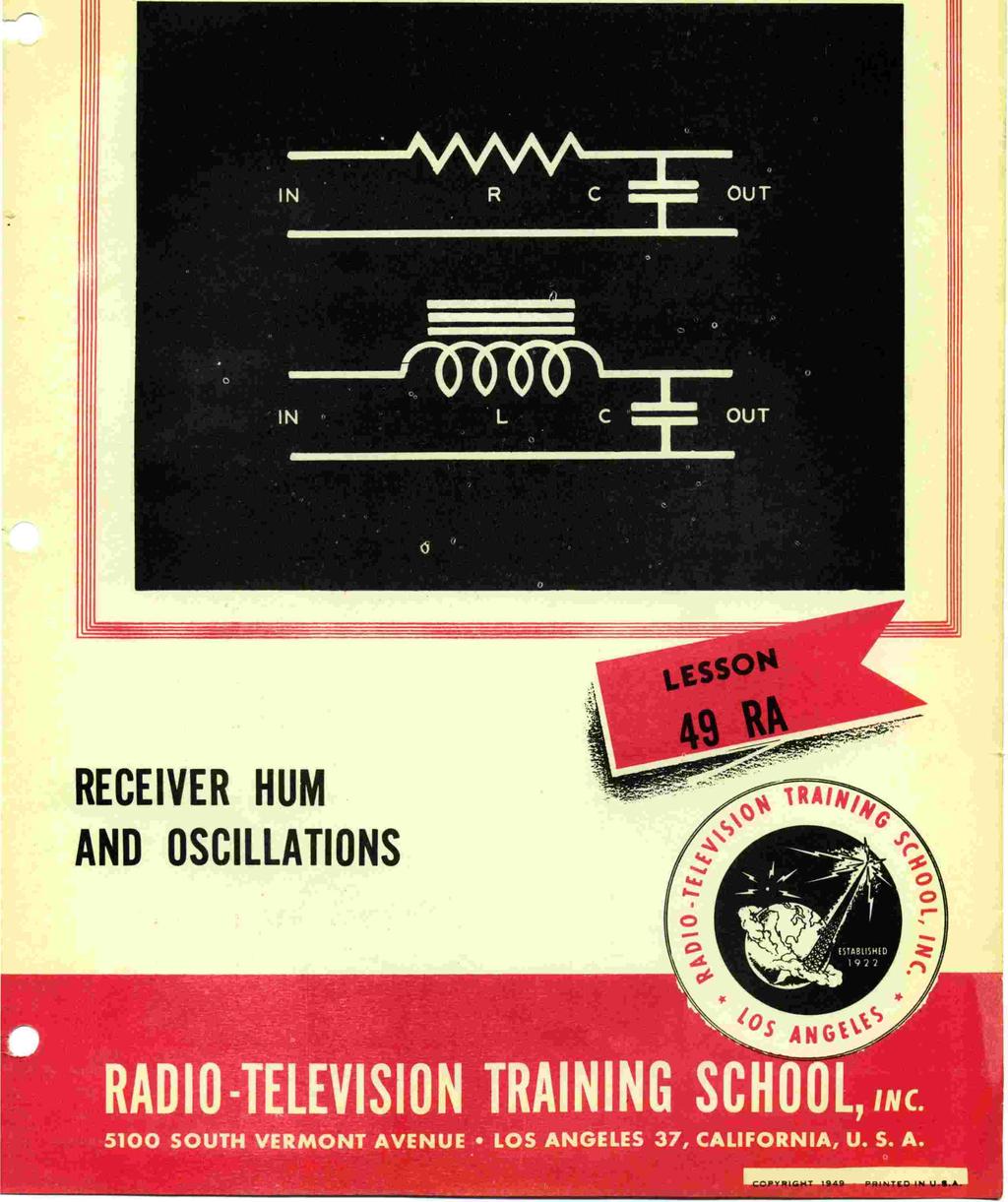
13 18) Distortion in some of the early A.V.C. sets can often be eliminated and the set performance greatly improved at the same tibe by using a smaller grid return condenser. 19) To add an antenna trimmer to a receiver not equipped with one, connect a.002 condenser in series with the stator of the first tuning condenser and install a midget trim.mer condenser connected across the secondary of the first coil. 20) A howl_in the 2nd audio or output tube may be caused by no load being on its grid while the 27 tube in the 1st stage heats up. Shunting a 2-meg resistor across the secondary of the 2nd transformer usually cures this. 21) The sensitivity of many midget sets using a grid bias screen grid detector can often be increased by inserting a mfd. condenser shunted by a 250M-ohm resistor in series with the grid lead of the tube. r 22) volume and poor tone quality from sets using dual speakers are often due to the speakers being improperly phased. The condition can be cor- 23l rected by reversing the voice coil leads of one speaker. Abrupt changes in receiver volume when different light switches in a house are turned on or off, can often be cured by shunting a 0.1-mfd condenser across the switch that is the worst offender. Poor selectivity and low volume, as well as intermittent reception, are often caused by the insulation becoming worn or breaking down on wires where they pass through small holes in the metal chassi. 25) The tinny or harsh tone of an output pentode tube can often be greatly improved and the base response brought out by connecting a high resistor (1/2 to 1 megohm) in series with a.1-mfd condenser across the control grid and plate terminals at the socket. Cover Diagram: Two effective filter circuits shown on the cover of this lesson do not require critical circuit values. Any value of R from 5 to 50,000 ohms, value of L from 6 to 50 henrys of inductance, and any value from 2 to 60 mfd. may be used. The inductor is used in circuits carrying a considerable amount of current. Remember that the large the values of any of the components, the better the filtering action.,, loi47r4912 Page 12
The Vibrator Power Supply
 The Vibrator Power Supply Function: The function of the vibrator power supply is like that of the AC operated supply - to provide the necessary voltages for the receiver. In this case the voltage source
 file:///c /BoatAnchors/Hammarlund/HQ170A/HQ170SVC.TXT Dear OM: This form is being prepared to provide prompt attention to a complaint as a result of trouble that may be experienced in the field. In addition
You Just Brought an Old Radio Home: Now What Do You Do?
 You Just Brought an Old Radio Home: Now What Do You Do? Raymond Cady goldenageradiorestoration.com Whether you are just beginning to collect antique radios or you have been at it for a number of years,
TABLE OF CONTENTS TEST EQUIPMENT R-F Signal Generator... 2 I-F CIRCUITS Page No. INTRODUCTION... 1 BASIC PROCEDURE...
 TABLE OF CONTENTS Page No. INTRODUCTION... 1 BASIC PROCEDURE... 1 TEST EQUIPMENT... 2 Vacuum-Tube Voltmeter... 2 R-F Signal Generator... 2 POWER SUPPLIES... 2 General Function of the Power Supply... 2
A 100-Watt Transmitter Using a Pair of VT1625s
 12/16/2007 6:00 PM VT1625 100 Watt Transmitter A 100-Watt Transmitter Using a Pair of VT1625s FIG. 10.6 A 100-watt transmitter for five bands, using salvaged TV power transformer and surplus 1625 amplifier
UNITED MOTORS SERVICE D IV ISIO N OF GENERAL M O TO RS C O R P O R A T IO N. General Offices - Detroit AUTO RADIO BULLETIN
 UNITED MOTORS SERVICE D IV ISIO N OF GENERAL M O TO RS C O R P O R A T IO N General Offices - Detroit AUTO RADIO BULLETIN Page 1 FIRST ISSUE SUBJECT: SERVICE INSTRUCTIONS - CHEVROLET TRUCK MODEL 987187
THE 1956 ZENITH ROYAL 500 TRANSISTOR OWL S EYES RADIO.
 THE 1956 ZENITH ROYAL 500 TRANSISTOR OWL S EYES RADIO. Dr. H. Holden. Feb. 2018. Introduction: The Zenith Royal 500 radio appeared in 1956, two years later than the Regency TR1 which was the first commercial
RCA Radiola 60 REG. U.S. PAT. OFF.
 RCA Radiola 60 REG. U.S. PAT. OFF. Super-Heterodyne AC Socket-Powered Instructions IB-60-1 Radio Corporation of America 233 Broadway New York City 100 West Monroe Street 235 Montgomery Street Chicago,
Archivist s Note: The plans are mislabeled and are actually for a tube-driven tremolo. See letter to the editor at the end of this document.
 Archivist s Note: The plans are mislabeled and are actually for a tube-driven tremolo. See letter to the editor at the end of this document. Build Your Own Vibrato Make like Elvis with an "electronic"
His Master s Voice SERVICE MANUAL FIVE-VALVE VIBRATOR POWERED BATTERY RECEIVERS. fo r. Model 329 Model 359. Dual - Wave Broadcast
 PRIVATE A N D C O N F ID E N T IA L FOR TRADE USE O N L Y His Master s Voice I f SERVICE MANUAL fo r FIVE-VALVE VIBRATOR POWERED BATTERY RECEIVERS Dual - Wave Broadcast Model 329 Model 359 TECHNICAL SPECIFICATION
A 75-Watt Transmitter for 3 Bands Simplified Shielding and Filtering for TVI BY DONALD H. MIX, W1TS ARRL Handbook 1953 and QST, October 1951
 A 75-Watt Transmitter for 3 Bands Simplified Shielding and Filtering for TVI BY DONALD H. MIX, W1TS ARRL Handbook 1953 and QST, October 1951 The transmitter shown in the photographs is a 3-stage 75-watt
Rodiolo m. Radio Corporation of ~meric Broadway. NewYorkCiiy.
 Rodiolo m Radio Corporation of ~meric4 233 Broadway. NewYorkCiiy. RodiolQ m Radio Corporation of v4mqriccl 233 Broadway. New York City. Fi l1. l --'Radiol III a Radiola III INTRODUCTION The RADIOLA III
D ELCO. electronic parts AUTO RADIO BULLETIN. Connect Signal Generator to
 D ELCO electronic parts AUTO RADIO BULLETIN Bulletin 6D-864 Date 10-15-56 Page 1 FIRST ISSUE SUBJECT: SERVICE INSTRUCTIONS - CHEVROLET CUSTOM DELUXE WITH PUSH BUTTON TUNING - MODEL 987575 GENERAL M O U
REPAIRING THE RM KL400 LINEAR AMPLIFIER.
 REPAIRING THE RM KL400 LINEAR AMPLIFIER. Les Carpenter G4CNH December 2012 Page 1 of 20 The following is a step by step guide to fixing your KL400 amplifier. Each part will be individually tested up to
UNITED MOTORS SERVICE D IV ISIO N OF GENERAL M O TO RS C O R P O R A T IO N. General Offices - Detroit AUTO RADIO BULLETIN
 UNITED MOTORS SERVICE D IV ISIO N OF GENERAL M O TO RS C O R P O R A T IO N General Offices - Detroit AUTO RADIO BULLETIN Bulletin 6D-855 Date 11-1-54 Page 1 FIRST ISSUE SUBJECT: SERVICE INSTRUCTIONS -
A-C/D.0 AND PORTABLE RECEIVERS. fecco't RRT -1 1
 A-C/D.0 AND PORTABLE RECEIVERS fecco't RRT -1 1 Radio Reception and Transmission LESSON RRT -11 A -C /D -C AND PORTABLE RECEIVERS CHRONOLOGICAL HISTORY OF RADIO AND TELEVISION DEVELOPMENTS 1913- Continuous
INSTRUCTIONS FOR INSTALLATION AND OPERATION OF THE MEISSNER SIGNAL SHIFTER MODEL EX
 INSTRUCTIONS FOR INSTALLATION AND OPERATION OF THE MEISSNER SIGNAL SHIFTER MODEL EX I. INTRODUCTION A. The MEISSNER SIGNAL SHIFTER is a variable frequency exciter, with output over the entire ranges of
CHEVROLET RADIO. SERVICE and SHOP MANUAL
 CHEVROLET RADIO SERVICE and SHOP MANUAL 1961 RADIOS 988414-PUSH BUTTON RADIO 988413-MANUAL RADIO 988468-CORVAIR PUSH BUTTON RADIO 988460-CORVAIR MANUAL RADIO 985003-CORVETTE RADIO 985036-MANUAL TRUCK RADIO
Calibration Testing of the Hickok Model 800/800A Tube Testers Version 1.0, September 2006 Daniel Schoo
 Calibration Testing of the Hickok Model 800/800A Tube Testers Version 1.0, September 2006 Daniel Schoo Use this procedure to test and calibrate the Hickok Model 800/800A mutual conductance (AKA transconductance)
UNITED MOTORS SERVICE. DIVISION OF GENERAL MOTORS CORPORATION General Offices - Detroit AUTO RADIO BULLETIN
 UNITED MOTORS SERVICE DIVISION OF GENERAL MOTORS CORPORATION General Offices - Detroit AUTO RADIO BULLETIN Bulletin 6D-848 Chevrolet 986515 Page 1 SUBJECT: SERVICE INSTRUCTIONS CHEVROLET CUSTOM DELUXE
Radar. Radio. Electronics. Television. .104f 4E011 UNITED ELECTRONICS LABORATORIES LOUISVILLE
 Electronics Radio Television.104f Radar UNITED ELECTRONICS LABORATORIES LOUISVILLE KENTUCKY REVISED 1967 4E011 1:1111E111611 COPYRIGHT 1956 UNITED ELECTRONICS LABORATORIES POWER SUPPLIES ASSIGNMENT 23
MODEL PD PEARSON DETECTOR
 MODEL PD PEARSON DETECTOR FIVE SECTIONS of QUICK INFORMATION I. Model PD Functions II. Operation Methods III. Apparatus IV. Instructions for Unpacking & Inspection V. Operating Instructions TINKER & RASOR
! February 9, 1970 GR-78!! Bulletin No: Transistor General Coverage Rcvr!
 ! February 9, 1970 GR-78-1! Rocker Switches [PN 60-45] S.P.S.T. switch is being replaced by [PN 60-48] D.P.D.T. switch with improved contacts. Four of the six lugs are removed when it is used as a S.P.S.T.
Some KWM-2/2A Tricks. January By Georges, F6CER CCAE# 098. Some KWM-2/2A Tricks -
 Some KWM-2/2A Tricks January 2016 By Georges, F6CER CCAE# 098 Some KWM-2/2A Tricks Most of the KWM-2 transceivers that can be found in Europe belong to the first generation manufactured at the beginning
UNITED MOTORS SERVICE AUTO RADIO BULLETIN
 UNITED MOTORS SERVICE DIVISION OF GENERAL MOTORS CORPORATION General Offices - Detroit AUTO RADIO BULLETIN Bulletin 6D-854 Date 11-1-54 Page 1 FIRST ISSUE GENERAL SUBJECT: SERVICE INSTRUCTIONS - 12V CHEVROLET
6 Tube Single Control Set. 5 Tube Tuned Radio Frequency Set. 4 Tube Popular Uncle Sam Set. 3 Tube All Wave Set. (20 to 550M.)
") 6 Tube Single Control Set 5 Tube Tuned Radio Frequency Set 4 Tube Popular Uncle Sam Set 4 Tube Screen Grid Set 3 Tube All Wave Set. (20 to 550M.) 13-Eliminator for A. C. Current It EDITION SIG. N&WMAINI
6 Tube Single Control Set 5 Tube Tuned Radio Frequency Set 4 Tube Popular Uncle Sam Set 4 Tube Screen Grid Set 3 Tube All Wave Set. (20 to 550M.) 13-Eliminator for A. C. Current It EDITION SIG. N&WMAINI
51J-4 COMMUNICATIONS RECEIVER
 51J-4 COMMUNICATIONS RECEIVER Transcribed from 520-5014-00 August 15, 1954 GENERAL DESCRIPTION The Collins 51J-4 Receiver is designed for communication applications where stability and dial accuracy of
COMPONENT LOCATION INDEX
 COMPONENT LOCATION INDEX 2004 ACCESSORIES & EQUIPMENT Audio System - TSX Fig. 1: Locating Audio System Components (1 Of 2) Tuesday, March 11, 2008 3:35:47 3:35:51 PM Page 1 Fig. 2: Locating Audio System
A Simple Electronic Organ. VOL. 16 No. 6 IN THIS ISSUE. Alumni Association News. Analyzing a Typical AC -DC Receiver
 Dec. -Jan. 1954-1955 IN THIS ISSUE Analyzing a Typical AC -DC Receiver A Simple Electronic Organ Alumni Association News VOL. 16 No. 6 :wawr.a=n X 3T gives me great pleasure once again to have the opportunity
The Electro-Magnetic Spectrum
 The Electro-Magnetic Spectrum Part Three In This Issue: All about Tubes How a diode rectifier works How a triode amplifier works How the mixer in your receiver works Dear Friends: For quite some time I
Assembly Instructions for the 1.5 Watt Amplifier Kit
 Assembly Instructions for the 1.5 Watt Amplifier Kit 1.) All of the small parts are attached to a sheet of paper indicating both their value and id. 2.) Leave the parts affixed to the paper until you are
May 23, Diode Leakage In The SB-100, SB-101, HW-100
 May 23, 1974 Diode Leakage In The, SB-101, HW-100-1 The silicon diodes used in the SB100 & SB101 are standard power diodes rated at 500PIV & 750MA. For each condition described, the diodes should be replaced
RangeMaster Trouble-shooting Manual
 RangeMaster Trouble-shooting Manual Page # 2 1. Tools you should have 3 2. What to do first 3 2.1 Most common problems 4 4 5 6 3. Low Range 3.1 Low Range/ Audio 4. Low Range 5. Tracing audio problems 7
Building the Sawdust Regenerative Receiver
 Building the Sawdust Regenerative Receiver Introduction The Sawdust is a super regenerative receiver using the basic Armstrong design architecture. The receiver uses one toroidal transformer to provide
Technical Specifications - Characteristics
 Watt FM TRANSMITTER General Description This is a small but quite powerful FM transmitter having three RF stages incorporating an audio preamplifier for better modulation. t has an output power of 4 Watts
Vintage Radio Alignment: What It Is and How to Do It
 Vintage Radio Alignment: What It Is and How to Do It Copyright 2009 Bret s Old Radios Bret Menassa Member: ARCI, VRPS, OKVRC Presented at Radiofest 2009, Willowbrook,, IL Vibrations A musical instrument
Dynaco ST-70 Input Board
 A u dio L ab s Sheldon Stokes 11811 Island Cove Dr. Fort Wayne, IN 46845 stokes@spinn.net http://www.quadesl.com Dynaco ST-70 Input Board 1 Introduction This board is a drop-in replacement for the original
No.01 Transistor Tester
 Blocks used Tester Circuits No.01 Transistor Tester Electronic components may break down if used or connected improperly. Let s start with a simple tester circuit project designed to teach you how to handle
MC24O OWNER'S MANUAL STEREO POWER AMPLIFIER CONTENTS
 STEREO POWER AMPLIFIER MC24O CONTENTS GENERAL DESCRIPTION 1 TECHNICAL DESCRIPTION 1 PANEL FACILITIES 4 INSTALLATION 5 CONNECTIONS 5 Input Stereo 5 Input Twin Amp 5 Input Mono 6 Output Stereo or Twin Amp
Device Interconnection
 Device Interconnection An important, if less than glamorous, aspect of audio signal handling is the connection of one device to another. Of course, a primary concern is the matching of signal levels and
Troubleshooting Tutorial Page 1 Tech Note 4
 Page 1 Tech Note 4 Tools Required: RCA shorting plugs (Fabricate using Radio Shack # 274-339) Digital Voltmeter Soldering Iron & Associated items Screw drivers, Pliers (including needle nose), wire cutters
Current Draw (Circuit breakers and fuses blow. Burning smell or smoke)
") T r o u b l e s h o o t i n g Current Draw (Circuit breakers and fuses blow. Burning smell or smoke) Excessive current without signal present Fast current draw Medium current draw Slow current draw Runaway
T r o u b l e s h o o t i n g Current Draw (Circuit breakers and fuses blow. Burning smell or smoke) Excessive current without signal present Fast current draw Medium current draw Slow current draw Runaway
The 21st Century R-390A/URR Reference Y2K-R3 Edited 7/09: No Technical Changes Chapter 2 - Operation. Page Table Of Contents 2-1
 Edited 7/09: No Technical Changes Chapter 2 - Operation Page Table Of Contents 2-1 2.1 Introduction. 2-2 2.2 Controls and Indicators 2-2 2.3 Operating Instructions And Control Settings 2-9 2.3.1 Pre-operational
Building the Sawdust Regenerative Receiver
 Building the Sawdust Regenerative Receiver Introduction The Sawdust is a super regenerative receiver using the basic Armstrong design architecture. The receiver uses one toroidal transformer to provide
sb401-eco.txt Engineering change orders or Service Bulletions (all) [No date on fiche] LMO Change
![sb401-eco.txt Engineering change orders or Service Bulletions (all) [No date on fiche] LMO Change](/thumbs/95/124083994.jpg "sb401-eco.txt Engineering change orders or Service Bulletions (all) [No date on fiche] LMO Change") Engineering change orders or Service Bulletions (all) [No date on fiche] LMO Change -1D The [PN 110-32] is no longer available. In order to use [PN 100-40-LMO] it is necessary to add decoupling capacitors
Engineering change orders or Service Bulletions (all) [No date on fiche] LMO Change -1D The [PN 110-32] is no longer available. In order to use [PN 100-40-LMO] it is necessary to add decoupling capacitors
GRID CONTROLLED POWER SUPPLY IS A VERSATILE UNIT Uses Pair of RCA-2050 s for Wide Voltage Range
 10/30/07 11:55 PM Thyratrons GRID CONTROLLED POWER SUPPLY IS A VERSATILE UNIT Uses Pair of RCA-2050 s for Wide Voltage Range By J. H. OWENS, W2FTW and G. D. HANCHETT, W1AK/2 RCA Ham Tips Volume 6, Number
2 5 1 A Va c u u m T u b e
 251A 2 5 1 A Va c u u m T u b e P L A T E L E A D INSULATORS W SPRING CONNECTOR - P L A T E L E A D -FILAMENT LEADS CONNECTOR GRID LEAD Classification The 251A Vacuum Tube is a three element, air-cooled,
The 6LE8 One Tube Broadcaster
 The 6LE8 One Tube Broadcaster Introduction The purpose of this broadcaster is to transmit your favorite music to every AM radio in your home. The transmitting power is so low that it should not bother
22A3 Monaural Amplifier Owner s Manual
 22A3 Monaural Amplifier Owner s Manual www.bandwidthaudio.com sales@bandwidthaudio.com WARNING Never power on the amplifier without connecting a proper load Failure to do so will result in permanent damage
WA3RNC 30 METER CRYSTALPLEXER TRANSMITTER KIT ASSEMBLY INSTRUCTIONS
 WA3RNC 30 METER CRYSTALPLEXER TRANSMITTER KIT ASSEMBLY INSTRUCTIONS Description The WA3RNC 30 Meter Crystalplexer is a low power crystal controlled QRP transmitter offering a significantly improved tuning
MFJ-203 Bandswitched Dip Meter
 MFJ-203 Bandswitched Dip Meter Thank you for purchasing the MFJ-203 Bandswitched Dip Meter. The MFJ-203 Bandswitched Dip Meter is a solid state bandswitched adaptation of the traditional grid dip meter.
Grounded Grid Plus Vacuum Tube Preamplifier User Manual. Analog Metric
 Grounded Grid Plus Vacuum Tube Preamplifier User Manual Analog Metric Page 2 INTRODUCTION This Grounded Grid Plus preamplifier provides enhanced performance out of the original Grounded Grid design. This
DD 1 INSTRUCTION BOOKLET CONTENTS PAGE
 DD 1 INSTRUCTION BOOKLET CONTENTS PAGE 1 Discussion of Diversity Action 2 Antenna Recommendations 3 4 5 Operating Suggestions 6 7 8 9 Rejecter Theory and Operation 10 11 12 Four Curves on Rejecter Operation
PET1606J2F. Pilani Electron Tubes & Devices Pvt. Ltd. Water Cooled Triode. For Industrial RF Heating. Drop in equivalent of BW1606J2F
 Water Cooled Triode For Industrial RF Heating Drop in equivalent of BW1606J2F Output Power: 30 kw Anode voltage: 10 kv max Anode dissipation: 15 kw max Frequency up to 30 MHz Manufactured in India, in
D. Gillespie Designs. SCA-35 Capacitor Board. Installation Manual. D. Gillespie Designs with EFB TM
 D. Gillespie Designs SCA-5 Capacitor Board with EFB TM Installation Manual D. Gillespie Designs www.tronola.com Thank you for choosing our SCA-5 Capacitor Board with *EFB. We feel it is the single most
Western Electric 106 -A AMPLIFIER INSTRUCTION BULLETIN NO. 880, ISSUE NO. 2
 Western Electric 106 -A AMPLIFIER INSTRUCTION BULLETIN NO. 880, ISSUE NO. 2 Western Electric 106 -A AMPLIFIER Type Two -stage line or main Amplifier with bridging or matching input. A complete self -contained
CON NEX HP. OWNER'S MANUAL Full Channel AM/FM Amateur Mobile Transceiver TABLE OF CONTENTS TUNING THE ANTENNA FOR OPTIMUM S.W.R..
 TABLE OF CONTENTS PAGE SPECIFICATIONS... 2 INSTALLATION... 3 LOCATION... 3 CON NEX - 4300HP MOUNTING THE RADIO... 3 IGNITION NOISE INTERFERENCE... 4 ANTENNA... 4 TUNING THE ANTENNA FOR OPTIMUM S.W.R..
Western E/ectrk A V a c u u m T u b e
 295A Western E/ectrk 2 9 5 A V a c u u m T u b e Classification Filamentary air- cooled triode May be used as an audio-frequency amplifier or as a radio-frequency amplifier, modulator o r o s c i l l a
RADIO RECEIVERS BC-224-F BC-224-K BC-348-H BC-348-K BC-348-L BC-348-R
 T.O 12R2-2BC-112 HANDBOOK MAINTENANCE INSTRUCTIONS RADIO RECEIVERS BC-224-F BC-224-K BC-348-H BC-348-K BC-348-L BC-348-R PUBLISHED UNDER AUTHORITY OF THE SECRETARY OF THE AIR FORCE AF-WP-O-16 MAY 57 5,510
Filament Thoriated tungsten. Filament voltage...14 volts Nominal filament current... 6 amperes Average thermionic emission...
 Classification Filamentary Air-cooled Triode. Application May be used as an audio-frequency amplifier or modulator; or as a radiofrequency oscillator or amplifier. Dimensions Large four-pin bayonet base
Manual AMERITRON QSK-5PC T/R SWITCH PC BOARD INTRODUCTION
 Manual Instruction AMERITRON QSK-5PC T/R SWITCH PC BOARD INTRODUCTION The Ameritron QSK-5PC is a PIN diode QSK circuit board designed for use in Ameritron's AL-80A, AL-80B, AL-82, AL-1500 and AL- 1200
KWM-2/2A Transceiver THE COLLINS KWM-2/2A TRANSCEIVER
 KWM-2/2A Transceiver Click the photo to see a larger photo Click "Back" button on browser to return Courtesy of Norm - WA3KEY THE COLLINS KWM-2/2A TRANSCEIVER Unmatched for versatility, dependability and
Practical Tricks with Transformers. Larry Weinstein K0NA
 Practical Tricks with Transformers Larry Weinstein K0NA Practical Tricks with Transformers Quick review of inductance and magnetics Switching inductive loads How many voltages can we get out of a $10 Home
Receiver Operation at the Component Level
 Receiver Operation at the Component Level Unit 9. Activity 9.4. How a Receiver Works Purpose: The objective of this lesson is to allow the student to explore how a receiver works at the component level.
- have been successfully combined in the RCA -developed insulated -gate metal -oxide -
 A PUBLICATION OF RCA ELECTRONIC COMPONENTS AND DEVICES VOL. 27, NO. 3 1967, RADIO CORPORATION OF AMERICA OCTOBER, 1967 Using the MOS Field -Effect Transistor As a Product Detector and AGC Gate By W. M.
The KW 76A MOBILE RECEIVER
 The KW 76A MOBILE RECEIVER The KW 76A Receiver is designed primarily for mobile operation. The compact layout makes it particularly suitable for under dash mounting in a vehicle. When used at a Home station
Step 3. Remove the strings from your guitar.
 VSTK-1 Vintage Stratocaster Kit Please Read All Instructions Before Beginning. Tools you will need: Soldering Iron (35 watt preferably) Solder Wet Sponge Wire Clippers Electric Drill 3/16 Drill Bit 11/64
SUPERHETERODYNE RECEIVERS. fesso 14 RRT N. Ashland Ave., Chicago 14, Illinois
 SUPERHETERODYNE RECEIVERS fesso 14 RRT -9 2533 N. Ashland Ave., Chicago 14, Illinois Radio Reception and Transmission LESSON RRT -9 SUPERHETERODYNE RECEIVERS CHRONOLOGICAL HISTORY OF RADIO AND TELEVISION
L A B O R A T O R I E S 9740 COZYCROFT AVENUE * CHATSWORTH * CALIFORNIA (800) * (818) * FAX: (818)
 * (818) * FAX: (818)") 3CPX800A7 Hi-Mu Power Triode The Penta Laboratories 3CPX800A7 is a ceramic and metal power triode intended for use as a radiofrequency amplifi er in FM broadcast applications. Operation with zero grid
3CPX800A7 Hi-Mu Power Triode The Penta Laboratories 3CPX800A7 is a ceramic and metal power triode intended for use as a radiofrequency amplifi er in FM broadcast applications. Operation with zero grid
1 TRANSISTOR CIRCUITS
 FM TRANSMITTERS The first group of circuits we will discuss are FM TRANSMITTERS. They can be called SPY TRANSMITTERS, FM BUGS, or a number of other interesting names. They all do the same thing. They transmit
AM Radio Lab. How Stuff Works. Mission College. Brad #1 Brad #2 Brad #3 Brad #4. Introduction:
 How Stuff Works Hope College Mission College Name: AM Radio Lab Brad #1 Brad #2 Brad #3 Brad #4 Introduction: In this lab you will construct an AM radio receiver that operates without a battery. The energy
FarmPS-1 Table of Contents
 Copyright 2004 Grandad s Electronics Seattle, Washington, USA INSTRUCTION MANUAL Model FarmPS-1, 1.5V/90V Farm Radio Power Supply A- A+ FarmPS-1 Table of Contents Section Page Contents 1.0.............................
R` R. 1 BOX FOh:TVILLE IND. Vol. 14 DECEMBER, 1949 No. 12 PAID. .Ft MARSH AL '^ W COLE. Permit No. I. So. Plainfield, N. J.
 Vol. 14 DECEMBER, 1949 No. 12 CORNELL-DUBILIER ELECTRIC CORP. Hamilton Boulevard, South Plainfield, N. J. I-OSTMASTER: If undeliverable for any reason. notify stating reason, on Form. 3547 postage for
Section 10.3 Telephones
 Section 10.3 Telephones Telephones allow you to talk to friends over great distances by measuring the sound of one person's voice and recreating that sound in another person's ear. Telephones perform this
Assembly Instructions
 Assembly Instructions For the SSQ-2F 3.1 MHz Rife Controller Board Kit v1.41 Manual v1.00 2012 by Ralph Hartwell Spectrotek Services GENERAL ASSEMBLY INSTRUCTIONS Arrange for a clean work surface with
555 Morse Code Practice Oscillator Kit (draft 1.1)
") This kit was designed to be assembled in about 30 minutes and accomplish the following learning goals: 1. Learn to associate schematic symbols with actual electronic components; 2. Provide a little experience
This kit was designed to be assembled in about 30 minutes and accomplish the following learning goals: 1. Learn to associate schematic symbols with actual electronic components; 2. Provide a little experience
PAC-12 Kit Contents. Tools Needed Soldering iron Phillips screwdriver Wire stripper Wrenches, 7/16 and 1/2 Terminal crimp tool Pliers Solder
 PAC-2 Kit Contents Part Quantity Screws: 8/32 x 3/8 Screws: 8-32 x 5/6 Screw: 8-32 x /4 #8 internal tooth washers #8 solder lug ring terminals Bolt: Aluminum, /4-20 x.5 /4 internal tooth washer Nut: Aluminum
Central Electronics Model 600L Linear Amplifier
 INTRODUCTION This manual has been reproduced by James Lawrence, NA5RC, a 600L owner. Text no longer applicable such as insurance claim with the carrier has been deleted. Some capitalization and grammar
Electronic Pipeline Technology
 Pipe and Cable Locator Pearson Holiday Detector Model EPT- 1000 Electronic Pipeline Technology Electronic Pipeline Technology 26 Palomino Drive, Richmond Hill, Ontario, Canada, L4C 0P8 Tel: (905) 918-0025
ELECRAFT Application Note
 ELECRAFT Application Note Front Panel Microphone Circuit Modification Revision A, November 12, 2008 Copyright 2008, Elecraft, Inc., All Rights Reserved Background Some K3 owners have noted distorted transmit
Assembly Instructions for the FRB FET FM 70 Watt Amp
 Assembly Instructions for the FRB FET FM 70 Watt Amp 1.) Orient the circuit board with the diagram 2.) Use a narrow chisel tip 25-30 watt soldering iron for assembly 3.) All the small parts are taped onto
Hallicrafters SX-88 Owners Manual
 Hallicrafters SX-88 Owners Manual Images and text excerpted from original Hallicrafters literature. Section 1. General Description The Hallicrafters SX-88 represents the ultimate in precision communications
LBI-4938C. Mobile Communications MASTR II POWER AMPLIFIER MODELS 4EF4A1,2,3. Printed in U.S.A. Maintenance Manual
 C Mobile Communications MASTR II POWER AMPLIFIER MODELS 4EF4A1,2,3 Printed in U.S.A. Maintenance Manual TABLE OF CONTENTS DESCRIPTION.................................................... 1 CIRCUIT ANALYSIS.................................................
servicing radio made easy LEONARD C. LANE VOLUME 2 gernsback library inc. new york 11, n. y. How to Fix Transistor Radios and Printed Circuits
 VOLUME 2 radio servicing made easy LEONARD C. LANE AUTHOR OF How to Fix Transistor Radios and Printed Circuits New Shortcuts to TV Servicing gernsback library inc. new york 11, n. y. To my Father, a gentle
SELECTION OF LOCATIONS FOR ELECTRONICS PANEL AND SPEAKER CABINET
 peterson LOW NOTE FLUTE GENERATOR INSTALLATION INSTRUCTIONS SELECTION OF LOCATIONS FOR ELECTRONICS PANEL AND SPEAKER CABINET Before beginning the installation select a location to mount the electronics
NTX-30 TRANSMITTER. Circuit Description
 General Description: The National NTX-30 is an extremely flexible crystal-controlled transmitter having an RF output of 30 watts on the 10-, 20-, 40- and 80-meter amateur bands. It is complete and self-contained
NATIONAL. rfr1. Radio.Trician. Lesson Text No. 13. (2nd Edition) RADIO FREQUENCY AMPLIFICATION
 RADIO FREQUENCY AMPLIFICATION") NATIONAL RADIO institute Complete Cour s è in PRACTICAL RADIO IIII rfr1 á IIIIIIIIIIIIIIUIIIIIIIIIIIIt1I111IUIit111 II',_ Radio.Trician (Trade Mark Reg. U. S. Patent GRìce) Lesson Text No. 13 (2nd Edition)
NATIONAL RADIO institute Complete Cour s è in PRACTICAL RADIO IIII rfr1 á IIIIIIIIIIIIIIUIIIIIIIIIIIIt1I111IUIit111 II',_ Radio.Trician (Trade Mark Reg. U. S. Patent GRìce) Lesson Text No. 13 (2nd Edition)
RITEK RIT for Collins KWM-2/2A 10/01/2002
 RITEK RIT for Collins KWM-2/2A 10/01/2002 The RITEK RIT (receiver incremental tuning) control was developed for KWM-2/2A in 1992 to "clarify" received signals differing from the transmit frequency indicated
Warnings. Elite Series Waterproof Amplifiers
 Warnings Read these instructions and keep them for future reference. Carefully follow instructions and follow directions carefully. Keep the amplifier dry, as some liquids may contain minerals that corrode
How to use your antenna tuner.
 How to use your antenna tuner. There's more to it than what is in your manual or on most how to do it websites! http://www.arrl.org/tis/info/ant-tuner-op.html Here is a neat site with a "T" network simulator.
Western Electric D V a c u u m T u b e
 284D Western Electric 2 8 4 D V a c u u m T u b e Classification Fiiamentary air-cooied triode The tube is designed primarily for use as an audio-frequency amplifier or modulator and may be used as a replacement
The Walford Electronics Ford Receiver Kit Project Construction Manual
 The Walford Electronics Ford Receiver Kit Project Construction Manual Walford Electronics Ford Receiver construction manual V1.5 Page 1 of 22 Introduction The Ford receiver has four stages: The first stage
Austin AUSTIN ISOLATION TRANSFORMER (DUAL WINDING SERIES) Installation Instructions for
 Installation Instructions for") Austin Installation Instructions for AUSTIN ISOLATION TRANSFORMER (DUAL WINDING SERIES) Austin Insulators Inc. 70 Airport Road Mississauga, Ontario LT H, CANADA tel: (90) 0-; fax: (90) 0-0 e-mail: support@austin-insulators.com
Austin Installation Instructions for AUSTIN ISOLATION TRANSFORMER (DUAL WINDING SERIES) Austin Insulators Inc. 70 Airport Road Mississauga, Ontario LT H, CANADA tel: (90) 0-; fax: (90) 0-0 e-mail: support@austin-insulators.com
Transformer Protection
 Transformer Protection Nature of transformer faults TXs, being static, totally enclosed and oil immersed develop faults only rarely but consequences large. Three main classes of faults. 1) Faults in Auxiliary
Custom Pendant- Hardwire Assembly and Installation Instructions
 Custom Pendant- Hardwire Assembly and Installation Instructions CAUTION: BEFORE INSTALLING FIXTURE, MAKE SURE THE POWER TO THE CIRCUIT IS TURNED OFF AT THE MAIN FUSE BOX / CIRCUIT BREAKER UTILITY BOX.
A GOOD REGENERATIVE RECEIVER WITH SIMPLE FINE TUNING (2008)
") A GOOD REGENERATIVE RECEIVER WITH SIMPLE FINE TUNING (2008) A good SSB-CW-AM regenerative receiver with a fine tuning by moving the wooden stick with a grounded piece of PCB towards the coil. A good regenerative
A GOOD REGENERATIVE RECEIVER WITH SIMPLE FINE TUNING (2008) A good SSB-CW-AM regenerative receiver with a fine tuning by moving the wooden stick with a grounded piece of PCB towards the coil. A good regenerative
CHASING ELECTRICAL NOISE. The single most vexing challenge in troubleshooting..
 CHASING ELECTRICAL NOISE The single most vexing challenge in troubleshooting.. The Goal Here To give you the tools you need to methodically troubleshoot electrical noise. Why do we care? YOU CAN CRASH
DIY Tube Stereo 70 Board - TubeZone Assembled -Instructions - Page 1
 DIY Tube Stereo 70 Board - TubeZone Assembled -Instructions - Page 1 Board and portions of manual, (c) 2006 Shannon Parks & DIYtube.com. Version specific instructions (c) 2006 Ned Carlson and Tubezone.net
TM-800 Main Station. Instruction Manual. TELIKOU Systems All Rights Reserved
 Intercom System TM-800 Main Station Instruction Manual TELIKOU Systems All Rights Reserved I. Introduction Thank you for choosing TELIKOU intercom product. TM-800 main station is suitable for television
Interference & Suppression Page 59
 INTERFERENCE Interference & Suppression Page 59 Front-End Overload, Cross-Modulation What is meant by receiver overload? Interference caused by strong signals from a nearby transmitter What is one way