Electronic Pipeline Technology
|
|
|
- Lisa Gaines
- 5 years ago
- Views:
Transcription


 918-0033 www.ep-tech.")
1 Pipe and Cable Locator Pearson Holiday Detector Model EPT Electronic Pipeline Technology Electronic Pipeline Technology 26 Palomino Drive, Richmond Hill, Ontario, Canada, L4C 0P8 Tel: (905) Fax: (905)
2 2 Table of contents: 1) Theory of Operation 2) Receiver 3) Transmitter 4) Charge the Batteries 5) Start Operation 6) How to trace the pipeline and measure the depth. 7) How to start Pearson Holiday Detector Survey
3 3 Theory of operation: Dr. Pearson from the United States of America for the first time discovered that electromagnetic waves can be stored in a pipeline and create a circular electromagnetic field around the pipe. The receiver with a search coil is able to detect this magnetic field. This is the principle theory as to why most pipe and cable locators work. The Model EPT operates on what is known as the Conductive Principle. The Transmitter provides a distinctive electrical signal current and by doing proper application and installation, the current causes a flow to a loop which is the pipe and cable being investigated. An electrical current flowing in a pipe or Cable creates a circular Magnetic field. If an antenna coil is placed within that field, an electric current is induced in the antenna. This current can be amplified and heard on headphones, loudspeakers, or by visible meter. The relative loudness of the signal, with the position of the antenna coil, enables the operator to determine with precision the location of the pipe or cable and its depth below the ground surface. By understanding these principles, and the use of this equipment, it enables the operator to find out many factors such as; location of extension, open, or grounded. The Receiver has a high gain amplifier that employs Transistors and active filters for 750 HZ. The filter rejects interference of any AC and DC current except the pipe magnetic field. The search coil has low Impedance and has a gauge for 45 degree angle.. The pipeline locator is equipped with loud speakers and it is possible to connect it to earphones. There is a switch to test the Battery condition before operating. The audio frequency current causes a current flow in a Pipeline, creating an Electrical field around the pipeline. The Intensity of the electrical field depends upon the amount of current flowing in the pipeline.
4 4 This electrical field can be measured by placing a search coil in the same plane as the pipeline. As the coil moves back and forth making a right angle with the pipeline, the electrical field will be cancelled directly over the pipeline. A null will be noted as long as a relatively large amount of audio current is flowing in the pipeline. Using the null method, it is possible to follow the pipeline while a large amount of audio current is flowing in it. When a large amount of audio signal can be applied to a pipeline, and a suitable receiver is used, the practical depth of the pipeline locating can be extended to much greater depths. Pipeline at depths exceeding 35 feet have been accurately located by employing this equipment and method, and depths greatly exceeding this may be possible, depending on the condition of protecting coating. To locate deeply buried or submerged pipelines, the audio oscillators electrically connect to the pipeline at a convent location at either ends of the line, but properly at a terminus so the audio current will flow in one direction only. If the pipeline is well coated, the audio oscillator may be made though the water in the immediate vicinity of the pipeline terminus. If the pipeline is poorly coated or has no protective coating, the audio oscillate ground should be made through a well insulated cable to a point several hundred feet away from the oscillator and a right angle to the pipeline. After Audio frequency current is properly applied to the pipeline, the locating survey is conducted from a boat. The operator should place the search coil in a horizontal position with reference to the pipeline and as the boat makes am oblique traverse over the pipeline, a sharp null effect will be noted. By audible observation, the operator will notice a gradual rise in tones as the location of the pipeline is approached and the null effect should occur when the search coil is directly over the pipeline. This method and equipment can be used in locating pipelines in almost any situation. With well coated pipelines, the operator can advance away from the audio oscillator for several miles. Another positive aspect of this method is the tracing of an individual pipeline through a mass of pipelines, provided the one under study is isolated.
5 5 Receiver Model: EPT Specifications: 1) 8 step sensitivity selector start with A up to H 2) High and low switch gain for long distance tracing 3) Power ON and OFF selector and Battery condition tester 4) Search coil with an extra cable to connect to the Receiver 5) Audio Volume for loudspeakers or headphones 6) Nickel Cadmium rechargeable 7.2 volt Battery 7) Analog meter 100uv full scale is a rugged sealed meter, properly damped to visually display and follow the receiver signal. 8) Audio or Headphone alarm when receiving signal 9) Low consumption rate current max 25 mil amp. 10) Filtered input for only for 745 HZ and 4 HZ Audio Frequency with automatic gain Control AGC. 11) Ability to find exact pipe location point by using null method theory and find the approximately depth by the using 45 degree Rule.

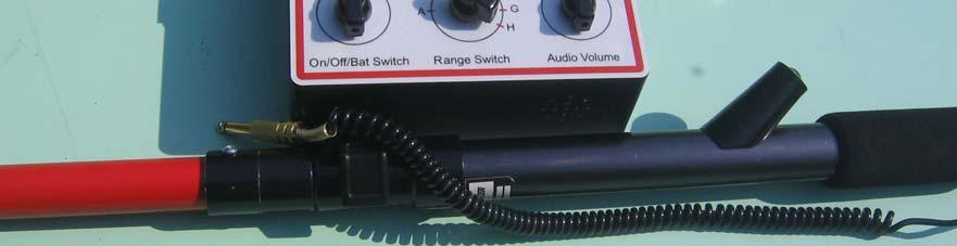

6 EPT RECEIVER 6
7 7 Transmitter Model: EPT The transmitter is designed to operate from a 12 DC volt External power sources. It contains a circuit that generates a distinctive AC 745 HZ signal. The signal is accompanied by an interruption signal 4 HZ to make the signal more distinctive. An operator has to connect the signal to the conductor and ground. Specifications: 1) Crystal Control Oscillator 2) Dual Transmitter Frequency 745 HZ and 4 HZ 3) Temperature Frequency Stabilized 4) Selectable output voltage from 2-75 volt to match the unit impedance with conductor with a visual meter indicator. 5) Enable and Disable Interruption Switch 6) Battery Test LED indicator 7) Heavy duty Pelican case Model 1350 and weight approximately 6.9 Lb.
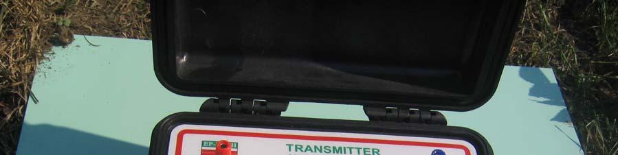

8 EPT Transmitter 8
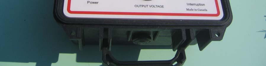
9 9 Transmitter (30 W) 1- Power selector: to match the output with pipeline impedance and has five steps. 2- Interruption switch: to distinguish transmitter from other sources. It has three steps. The first and second for matching the impedance with the pipeline and the third one is the interruption mode which disconnects the meter from the output power. 3- Output terminals for connecting it to the pipeline with two alligator connectors 4- Input Battery terminals: for connecting extra Battery or to charge the internal Battery 5- Battery condition LED tester 6- Switching charger for work from 90 up to 260 volt
10 10 How to start operation and trace the pipeline: Charge the Batteries of the Receiver and Transmitter. The receiver Battery is good if it is over the 80 Receiver scale meter. Connect the output of the transmitter to the pipeline and a remote ground wire perpendicular to the pipeline. Turn it on and Put the power selector on step A. Then select Interruption switch OFF. By changing the selector you have to find the Max voltage on the Meter. If the Meter is a full scale (scale =1 for output voltage) then select the middle state of interruption switch (scale = ½ output voltage) and then find the max voltage on the Meter. When you find the Max power step, you can change the Interruption switch ON and automatically the Meter will turn OFF. Normally when there is a big pipe and bad coating it, will start from low voltage and high Current up to a small pipe with good coating and will be in the end of the power selection with higher voltage. Connect the search coil to the Receiver. Put the Gain switch on low and Range switch on step A. Stay on the assumed pipeline, go back and forth to hear the interruption beep alarm, otherwise step by step increase the range switch to hear the beep. When the hearing the beep, the operator will approximately find the pipeline. Please put your volume very low on the red line. To find the pipeline location accurately, put the search coil in a vertical position to the ground and go back and forth suddenly. Only in one location the beep will stop and you have a null and if you continue the beep will start again. This null point is the exact location of the pipeline.

11 11
12 12 How to find the depth of the pipeline: When you find the exact location of the Pipeline, put your search coil in 45 degree angle by using the gauge on the top and perpendicular to pipe gently move back until the beep stop. The distance from the pipeline to this point is the depth of the pipe.
13 13 Pearson Holiday Detector: EPT detector is designed to locate discontinuities, flaws or breaks in the coating of buried pipelines. This method makes it possible to locate the exact location of coating breaks in buried lines without access to the surface of the coated pipe. Locating electrical discontinuities aids in evaluating the application of a coating and also these discontinuities can be repaired to eliminate corrosion and to reduce the amount of current required for cathodic protection. The method used to locate discontinuities is that of applying audio frequency A.C. energy between the coated pipe and ground. A traverse along the pipeline is made in with the difference in potential is indicated across approximately twenty to thirty feet of soil above the line. This potential difference is noted in the Receiver. When an area is reached where the difference in potential is considerably greater than the average potential over the pipe, a discontinuity is assumed to lie under this area. A loudspeaker is built into the Receiver, eliminating the need for earphones except in noisy areas. Plugging the earphones into the jack marked PHONES disables the loud speaker. Both operators have a pair of pogo sticks; both pogo sticks of an operator are parallel running the cables inside their pant legs. The key operator connects with wires from both of his Pogo sticks to the one input Receiver terminal. The secondary operator connects the

14 14 wires from both of his pogo sticks to the other input Receiver terminal. The Receive is turned "ON", and the apparatus is ready for use. The traverse along the pipeline is made by walking over the pipe at a slow speed. Beginning adjacent to the transmitter set the Receiver Selector so that the signal from the Transmitter can be heard at a very low level. As progress away from the Transmitter is made, the signal may drop and the level can be raised again by increasing the Selector level. A discontinuity is indicated by an increase in average signal level, followed by a relatively sharp decrease, and then another increase and then back to normal level as progress is made over the discontinuity.
15 15 The exact point of discontinuity lies under the point of decreased signal or null. This, then, is the point halfway between the two operators. If a series of discontinuities exist in close proximity to each other, the null effect may not be heard, or very difficult to observe. In this case, one man walks along the line and the other walks at right angles to the line and a discontinuity is noted by an increase in signal of voltage Gradient directly over the fault.
MODEL PD PEARSON DETECTOR
 MODEL PD PEARSON DETECTOR FIVE SECTIONS of QUICK INFORMATION I. Model PD Functions II. Operation Methods III. Apparatus IV. Instructions for Unpacking & Inspection V. Operating Instructions TINKER & RASOR
CIPS, DCVG & GPCM Pipeline Surveyor. Corrosion Control Equipment
 CIPS, DCVG & GPCM Pipeline Surveyor Corrosion Control Equipment Electronic Pipeline Technology 153 Milos Road Richmond Hill, Ontario, Canada, L4C 0P8 Tel: (905) 918-0025 Fax: (905) 918-0033 www.ep-tech.ca
Electronic Pipeline Technology Ltd
 Electronic Pipeline Technology Ltd www.ep-tech.ca E-mail: sales@ep-tech.ca Dear valued customers, Corrosion is a serious problem for pipelines and costs money. As you well know, cathodic protection is
ELECTRICAL SURVEY METHODS OF UNDERGROUND COATED PIPELINES
 R & SO R ELETRIL SURVEY METHOS OF UNERGROUN OTE LINES (Locating and Identifying Holidays and able reaks) y arrel. yerley Tinker & Rasor P.O. ox 281 San Gabriel, 91778 US www.tinker-rasor.com Info@tinker-rasor.com
Dynatel 2250E/2273E Advanced Cable and Fault Locator
 Dynatel 2250E/2273E Advanced Cable and Fault Locator Operators Manual September 1999 78-8097-6500-7-B TABLE OF CONTENTS Introduction... 2 Installing or Replacing the Batteries... 2 Initial Receiver Configuration...
Armada Technologies Pro800D Hi-Power Wire and Valve Locator. Operating Instructions
 Test Equipment Depot - 800.517.8431-99 Washington Street Melrose, MA 02176 TestEquipmentDepot.com Armada Technologies Pro800D Hi-Power Wire and Valve Locator Armada T echnologies Operating P ro800d Instructions
Armada Technologies Pro900 Advanced Underground Locator USER GUIDE
 Pro900 Advanced Underground Locator USER GUIDE WARNING Read and understand the instructions before operating this unit. Failure to do so could lead to injury or death. The Armada Technologies Pro900 Advanced
Armada Technologies Pro900 Advanced Underground Locator USER GUIDE
 Pro900 Advanced Underground Locator USER GUIDE WARNING Read and understand the instructions before operating this unit. Failure to do so could lead to injury or death. The Armada Technologies Pro900 Advanced
INDEX. Accessories and Components System Unit and Joystick Assembly and Charging the Battery Using with LED System...
 USER GUIDE INDEX Accessories and Components... 4 System Unit and Joystick... 6 Assembly and Charging the Battery... 9 Using with LED System... 11 What is Ground Setting and How It Is Done... 14 Ground
UNITED STATES PATENT OFFICE
 Patented Jan., 1937 2,066,61 UNITED STATES PATENT OFFICE 2,066,61 METALLOSCOPE Gerhard R. Fisher, Palo Alto, Calif. Application January 16, 1933, Serial No. 61,974 Renewed August 6, 1936 3 Claims. (Cl.
UTILITY LOCATING EQUIPMENT
 RIDGID SEEKTECH LOCATING RECEIVERS RIDGID locating receivers feature an easy-to-use visual mapping display that allows you to locate utility lines and sondes/beacons with confidence. Use with a SeeSnake
MODEL CI-5120 SEWER & CAMERA LOCATING RECEIVER
 Underground Detection Equipment OPE R A T IING MA NUA L MODEL CI-5120 SEWER & CAMERA LOCATING RECEIVER GOLDAK INC. 547 WEST ARDEN AVE. GLENDALE, CA 91203 PHONE: (818) 240-2666 FAX: (818) 244-6818 WEBSITE:
Pro871C Cable Locator Operating Instructions
 Pro871C Cable Locator Operating Instructions WARNING Read and understand the instructions before operating this unit. Failure to do so could lead to injury or death. The Armada Technologies Pro871C wire
Device Interconnection
 Device Interconnection An important, if less than glamorous, aspect of audio signal handling is the connection of one device to another. Of course, a primary concern is the matching of signal levels and
This manual applies to the WT-RC-Ex receiver when used to locate all makes and models of 22 Hz and Wavetrak coded transmitters.
 This manual applies to the WT-RC-Ex receiver when used to locate all makes and models of 22 Hz and Wavetrak coded transmitters. The Wavetrak WT-RC-Ex receiver kit comes with the following pieces of equipment:
PART E SPECIFICATIONS
 PART E SPECIFICATIONS Page 1 of 10 PART E - SPECIFICATIONS E1. GENERAL E1.1 These shall apply to the Work. E2. SCOPE E2.1 The City of Winnipeg Fire Paramedic Service is wishing to acquire new mobile and
PT-1. Pipe Tracker OPERATION MANUAL 1010 JW FISHERS MFG INC 1953 COUNTY ST. E. TAUNTON, MA USA
 Pipe Tracker OPERATION MANUAL 1010 JW FISHERS MFG INC 1953 COUNTY ST. E. TAUNTON, MA 02718 USA (508) 822-7330; (800) 822-4744; FAX (508) 880-8949 Email: jwfishers@aol.com WEB: www.jwfishers.com MAINTENANCE
UAT-600 Series. amprobe.com
 UAT-600 Series Underground Utilities Locator Accurately and safely pinpoint underground utilities before you dig Accidentally hitting a utility line during a project can lead to costly repairs and create
FIELD INTENSITY METER MODEL FIM-41 OPERATING INSTRUCTIONS
 FIELD INTENSITY METER MODEL FIM-41 OPERATING INSTRUCTIONS POTOMAC INSTRUMENTS, INC. 932 Philadelphia Ave. Silver Spring, MD 20910 Phone (301) 589-2662 Fax (301) 589-2665 www.pi-usa.com 2.1 General SECTION
CALRAD 25 series - potentiometers
 25 series - potentiometers audio /linear SUB-MINIATURE VOLUME CONTROLS Linear taper, extremely smooth for quiet operation. 1 2" dia. fits into 1 4" hole. Shaft 3 16" dia. Thread length 7 32", shaft length
CON NEX HP. OWNER'S MANUAL Full Channel AM/FM Amateur Mobile Transceiver TABLE OF CONTENTS TUNING THE ANTENNA FOR OPTIMUM S.W.R..
 TABLE OF CONTENTS PAGE SPECIFICATIONS... 2 INSTALLATION... 3 LOCATION... 3 CON NEX - 4300HP MOUNTING THE RADIO... 3 IGNITION NOISE INTERFERENCE... 4 ANTENNA... 4 TUNING THE ANTENNA FOR OPTIMUM S.W.R..
R E L I C S C A N Professional pulse induction metal detector
 REX TM Metal Detectors R E L I C S C A N Professional pulse induction metal detector User s guide www.rexmetaldetectors.com made in Bulgaria 1 In order to use the device for a maximum long time and without
pipeline integrity PCM + Pipeline Current Mapper
 pipeline integrity PCM + Pipeline Current Mapper Fast locate and effective measurement of pipeline coating defects. The location and measurement of pipeline corrosion using electromagnetic detection devices
BANDITO-GOLDEN MASK Bandito Impulse GOLDEN MASK METAL DETECTOR BANDITO PULSE INDUCTION USER S GUIDE
 GOLDEN MASK METAL DETECTOR BANDITO PULSE INDUCTION USER S GUIDE MADE BY GOLDEN MASK BULGARIA 2006 INSTRUCTION MANUAL THE DEVICE.. 3 TECHNICAL CHARACTERISTICS...3 METAL DETECTOR OPERATORS ETHICS......3
FX-3. Operating Manual. Q U A L I T Y Fisher detectors are renowned for their quality. Each detector is hand crafted in the USA with pride
 Q U A L I T Y Fisher detectors are renowned for their quality. Each detector is hand crafted in the USA with pride P E R F O R M A N C E The worldwide underground utility industry relys on Fisher. Our
CMA-100. Counter Measures Amplifier. Owner s Guide
 CMA-100 Counter Measures Amplifier Owner s Guide INTRODUCTION: Thank you for purchasing the CMA-100 Countermeasures Amplifier. When doing a Counter-surveillance investigation, it is important to analyze
AM Radio Lab. How Stuff Works. Mission College. Brad #1 Brad #2 Brad #3 Brad #4. Introduction:
 How Stuff Works Hope College Mission College Name: AM Radio Lab Brad #1 Brad #2 Brad #3 Brad #4 Introduction: In this lab you will construct an AM radio receiver that operates without a battery. The energy
GROUND TESTERS For all of your Ground Testing needs...
 GROUND TESTERS For all of your Ground Testing needs... An array of Ground Testers to choose from Whether you are doing a simplified 2-Point, a more complete 3- or 4-Point Fall-of-Potential test, a soil
INDEX PREFACE... 1 CAUTIONS... 2 OPERATION ON SITE(9) STANDARD INSTRUMENT... 3 OPTIONAL ACCESSORIES... 4 OPERATION OF TRANSMITTER(3)...
 STANDARD INSTRUMENT... 3 OPTIONAL ACCESSORIES... 4 OPERATION OF TRANSMITTER(3)...") INDEX PREFACE... 1 CAUTIONS... 2 STANDARD INSTRUMENT... 3 OPTIONAL ACCESSORIES... 4 OPERATION OF TRANSMITTER(1)... 5 (Transmitter Unit.) OPERATION OF TRANSMITTER(2)... 6 (Operation Panel, LCD Display of
INDEX PREFACE... 1 CAUTIONS... 2 STANDARD INSTRUMENT... 3 OPTIONAL ACCESSORIES... 4 OPERATION OF TRANSMITTER(1)... 5 (Transmitter Unit.) OPERATION OF TRANSMITTER(2)... 6 (Operation Panel, LCD Display of
AT-4000 Advanced Tracer User s Manual
 AT-4000 Advanced Tracer User s Manual Amprobe thanks you for purchasing the AT-4000 Advanced Tracer. For your safety, please read this instruction manual in its entirety. LIMITED WARRANTY VÉÇzÜtàâÄtà ÉÇá4
SEARCH LITE OPERATION MANUAL
 SEARCH LITE OPERATION MANUAL Corporate Profile Trilithic, Inc. was founded in 1986 as an engineering and assembly company providing customized communications and routing systems for business and government
Dynatel. 2273M Cable/Pipe and Fault Locators 2273M-iD Cable/Pipe/Fault and Marker Locators with id Read/Write
 3 Dynatel 2273M Cable/Pipe and Fault Locators 2273M-iD Cable/Pipe/Fault and Marker Locators with id Read/Write Designed to be more accurate, faster and more integrated than any other locator on the market,
ZT-30 ZeroTEM TRANSMITTER MANUAL
 ZT-30 ZeroTEM TRANSMITTER MANUAL 06 September, 2000 Zonge Engineering and Research Organization, Inc. 3322 East Fort Lowell Road, Tucson, AZ 85716 USA Tel:(520)327-5501 Fax:(520)325-1588 Email:zonge@zonge.com
User Manual 8880 Series Fault Finding & Locating Kit
 User Manual 8880 Series Fault Finding & Locating Kit Model 8880PLS STAFF Model 8880PLS HVDFF Manual Part # 030-00085-00 Rev E Table of Contents General Information Introduction...............................................
STAFF User Manual. Manual Part #
 STAFF User Manual Manual Part # 030-00085-00 Introduction Congratulations on the purchase of your new STAFF Secondary Fault Locator. The STAFF is specially designed to detect conductor to earth/ground
ReSound Micro and Multi Mic
 Tip for use of FAQ: Click on questions to go to answer. Setup & Configuration How do I pair the hearing aids to the Micro and Multi Mic?... 3 How many hearing aids can the Micro/Multi Mic be paired with?...
Report. Mearns Consulting LLC. Former Gas Station 237 E. Las Tunas Drive San Gabriel, California Project # E
 Mearns Consulting LLC Report Former Gas Station 237 E. Las Tunas Drive San Gabriel, California Project #1705261E Charles Carter California Professional Geophysicist 20434 Corisco Street Chatsworth, CA
Pipeline Current Mapper
 Pipeline Current Mapper Locate Accurately find buried pipes, establish centerline depth, then troubleshoot coating defects Record Stores up to 1000 measured PCM and location data in memory within the receiver
Operation Manual for CTL-3000
 CATH-TECH CORROSION CONTROL EQUIPMENT Operation Manual for CTL-3000 DCVG Survey Instrument Cathodic Technology Ltd. 15-1 Marconi Court Bolton, Ontario Canada L7E 1E2 Ph: ++1-905-857-1050 ctl@cath-tech.com
CMA-100. User Manual. Counter Measures Amplifier
 CMA-100 Counter Measures Amplifier User Manual Research Electronics International, LLC 455 Security Drive, Cookeville, TN 38506 U.S.A. (800) 824-3190 (US Only) +1 931-537-6032 www.reiusa.net Copyright
WMD Wired microphone detector. Manufactured by SOLITON-TRON Ltd. HUNGARY
 WMD-2000 Wired microphone detector Manufactured by SOLITON-TRON Ltd. HUNGARY The WMD-2000 Acoustically Stimulated Microphone Detector is an electronic system for use by TSCM Inspectors for detecting audio
GC-1032 Metal Detector OWNER S MANUAL
 GC-1032 Metal Detector OWNER S MANUAL 1 With your GC-1032 metal detector, you can hunt for coins, relics, jewelry, gold, and silver just about anywhere. The detector comes with high sensitivity and strong
Boulder W Class A Stereo Power Amplifier
 Boulder 2060 600 W Class A Stereo Power Amplifier Owners Manual V1.0 10/10/97 TABLE OF CONTENTS GETTING STARTED Placement of the 2050 Power amplifier......................................... 1-1 Connecting
Instruction Manual. Model XTpc-33 khz Pipe & Cable Locator
 Instruction Manual Model XTpc-33 khz Pipe & Cable Locator Manufactured By Schonstedt Instrument Company Made in USA Preface The Model XTpc Pipe & Cable Locator is a product of over fifty years experience
PS 19 AM SINGLE CHANNEL BELTPACK IN METAL CASE WITH PGM (AUX) INPUT
 INPUT") PS 19 AM SINGLE CHANNEL BELTPACK IN METAL CASE WITH PGM (AUX) INPUT USER MANUAL August 2016 This product is designed and manufactured by: ASL Intercom BV Zonnebaan 42 3542 EG Utrecht The Netherlands Phone:
PS 19 AM SINGLE CHANNEL BELTPACK IN METAL CASE WITH PGM (AUX) INPUT USER MANUAL August 2016 This product is designed and manufactured by: ASL Intercom BV Zonnebaan 42 3542 EG Utrecht The Netherlands Phone:
PR-216. High Performance Personal Receiver PR-216 OPERATOR S MANUAL
 PR-216 OPERATOR S MANUAL PR-216 High Performance Personal Receiver 357 West 2700 South Salt Lake City, Utah 84115 Phone: (800) 496-3463 Fax: (801) 484-6906 http://www.comtek.com TABLE OF CONTENTS Introduction...
Fault Mapper Cable Length Meter & Fault Locator Alphanumeric TDR Model CA7024
 Fault Mapper Cable Length Meter & Fault Locator Alphanumeric TDR Model CA7024 The Fault Mapper Model CA7024 is a hand-held, alphanumeric, TDR (Time Domain Reflectometer) Cable Length Meter and Fault Locator,
Massachusetts Institute of Technology MIT
 Massachusetts Institute of Technology MIT Real Time Wireless Electrocardiogram (ECG) Monitoring System Introductory Analog Electronics Laboratory Guilherme K. Kolotelo, Rogers G. Reichert Cambridge, MA
Pathfinder. Instruction Manual for: PF620 Circuit Tracer Kit
 Pathfinder Instruction Manual for: PF620 Circuit Tracer Kit Table of Contents Page Safety Considerations...3 Introduction...4 Specifications...5 Theory of Operation...6 Single Phase Circuits Locating Circuit
Amateur Wireless Station Operators License Exam
 Amateur Wireless Station Operators License Exam Study material 2017 South India Amateur Radio Society, Chennai CHAPTER 5 1 Chapter 5 Amateur Wireless Station Operators License Exam Study Material Chapter
Golden Mask DEEP HUNTER Pro3
 Golden Mask DEEP HUNTER Pro3 Golden Mask Deep Hunter Pro3 is a professional metal detector designed to detect deeply buried large metal objects (larger than 8 cm). It has the ability to indicate the type
CALRAD MINIATURE MULTI-CLICK DUAL CONTROLS 40 STEP P.C. MOUNT 11
 25 Series - Potentiometers Audio & Linear SUB-MINIATURE VOLUME CONTROLS Linear taper, extremely smooth for quiet operation. 1 /2" dia. fits into 1 /4 hole. Shaft 3 /16" dia. Thread length 7 /32", shaft
GFL-1000 User Manual Ground Fault Locator
 GFL-Series User Manual V1.1 GFL-1000 User Manual Ground Fault Locator Contents Contents... 1 1 Declaration of Conformity... 3 2 Introduction... 3 3 Equipment Information... 3 3.1 Safety Precautions...
DUNHAM & MORROW By Schonstedt Instrument Company Tel: Fax:
 DUNHAM & MORROW By Schonstedt Instrument Company Tel: 304-724-4790 Fax: 304-724-4725 dml@schonstedt.com www.magneticlocator.com 1 Quick Start Instructions 1. Make yourself magnetically clean. Typical items
DX AM FM SSB CW PA Amateur Base Station Transceiver OWNER S MANUAL RX / TX 2 4 POWER NF CHANNEL MODE RF POWER OFF CAL OFF OFF CALIBRATE
 1 2 3 6 4050 ULA 6070 TI 80 90 100 9 DX 2517 2517 RX / TX 0 2 4 SWR WATTS SET 81012 22 1 010 3 2030 5 MOD 7 ON dbover 9 SIGNAL +20 +40+60 PA FM AM USB LSB CW POWER ON SWR NB / ANL R.BEEP +10KHz NF CHANNEL
.2 Section Waste Management and Disposal..4 Section Electrical General Requirements.
 Issued 2006/08/01 Section 16724 Public Address System Page 1 of 8 PART 1 GENERAL 1.1 RELATED SECTIONS.1 Section 01330 Submittal Procedures..2 Section 01355 Waste Management and Disposal..3 Section 01780
PROFESSIONAL POWER AMPLIFIERS. User Instructions. American DJ V3000 LIMITER. American DJ LIMITER I LIMITER. ON channel 2
 & PROFESSIONAL POWER AMPLIFIERS User Instructions American DJ SIG 20 10 5 CLIP PROTECT POWER PROTECT CLIP 5 10 20 SIG PROformer Series V3000 channel 1 ON ON channel 2 I O Professional Stereo Amplifier
2011 / Circuit Tracer
 INSTRUCTION MANUAL 2011 / 00521 Circuit Tracer Read and understand all of the instructions and safety information in this manual before operating or servicing this tool. 52044992 2008 Greenlee Textron
PLA-240. Small Room Loop Amplifier System. USER Manual MAN 211A
 PLA-240 Small Room Loop Amplifier System USER Manual MAN 211A Overview Thank you for purchasing the PLA 240 Small Room Loop Amplifier System. The PLA 240 Loop System provides a practical solution for hearing
Telephone Cable Locating Techniques
 Chapter 2 Telephone Cable Locating Techniques Introduction Read Chapter One of this manual to learn more general information about each of the following signal application methods. The following paragraphs
DCVG Coating Survey Data Sheet
 DCVG Coating Survey Data Sheet DCVG COATING DEFECT SURVEYS Today, DC voltage gradient surveys have evolved as an accurate and economic means of locating coating defects. When a DC current is applied to
MFJ-208 VHF SWR Analyzer
 MFJ-208 VHF SWR Analyzer Thank you for purchasing the MFJ-208 VHF SWR Analyzer. The MFJ-208 gives you a direct readout of your antenna's SWR without the need for formulas or indirect readings. The MFJ-
TW-82 DIGITAL LINE TRACER. Operating Manual
 TW-82 DIGITAL LINE TRACER Operating Manual CONTENTS Introduction... pg. 3 Transmitter...pg. 4-6 Receiver...pg. 7-9 Specifications...pg. 10 Warranty...pg. 11 Accessories...pg. 12 INTRODUCTION The TW-82
Radio and Electronics Fundamentals
 Amateur Radio License Class Radio and Electronics Fundamentals Presented by Steve Gallafent September 26, 2007 Radio and Electronics Fundamentals Voltage, Current, and Resistance Electric current is the
Owner s manual & Installation manual Mode d emploi et manuel d installation Manual de instrucciones y de instalación XC6210 XC6410
 Owner s manual & Installation manual Mode d emploi et manuel d installation Manual de instrucciones y de instalación XC6210 XC6410 XC AMPLIFIERS AMPLIFICATEURS XC AMPLIFICADORES XC INTRODUCTION The Clarion
F I S H E R R E S E A R C H L A B O R A T O R Y
 TW-82 DIGITAL LINE TRACER Operating Manual F I S H E R R E S E A R C H L A B O R A T O R Y CONTENTS Introduction...pg. 3 Transmitter...pg. 4-5 Receiver...pg. 6-8 Operating Instructions...pg. 9 Specifications...pg.
BUILDING INSTALLATIONS AND ELECTRICAL SYSTEMS
 BUILDING INSTALLATIONS AND ELECTRICAL SYSTEMS The right electrical tester for all applications. The user guide provides an overview of electrical test segments and working ranges. Working ranges AC-tiveFinder
CHANCE Proximity Voltage Indicator
 Revision D 10/16 CHANCE Proximity Voltage Indicator Operating Instructions Model No. PSC4033737 For use with Capacitive Test Point through 500 kv AC NOTICE: Before operating a Chance Proximity Voltage
Instruction Manual. Model GA 92 XTd Magnetic Locator
 Instruction Manual Model GA 92 XTd Magnetic Locator Manufactured By Schonstedt Instrument Company 100 Edmond Road Kearneysville, WV 25430 (304) 725 1050 Fax (304) 725 1095 Web: www.schonstedt.com E mail:
Handy dandy little circuit #17 #17
 Handy dandy little circuit #17 #17 Download # 17 in PDF There are a lot of alarm systems on the market but you might be inclined to build your own. This little project can be put together using inexpensive
Technical Equipment Specification
 STATE OF CALIFORNIA Office of the State Chief Information Officer Public Safety Communications Division Technical Equipment Specification Equipment Type: Transmitter/Receiver Mobile Relay/Base/Control
TW-82 TW-82 ACCESSORIES. Operating Manual DIGITAL LINE TRACER F I S H E R R E S E A R C H L A B O R A T O R Y
 TW-82 ACCESSORIES 3 Inch Coupling Clamp CCLAMP-3 Useful for in-service and electrical power line tracing when a metal-to-metal hookup is not possible TW-82 DIGITAL LINE TRACER 5 Inch Coupling Clamp CCLAMP-5
SI-125 Power Amplifier Manual 6205 Kestrel Road; Mississauga, Ontario; Canada; L5T 2A1 November 2016, Rev 0.5
 SI-125 Power Amplifier Manual 6205 Kestrel Road; Mississauga, Ontario; Canada; L5T 2A1 November 2016, Rev 0.5 Phone: (905) 564-0801 Fax: (905) 564-0806 www.telecor.com E:\T2-108\T2-M108-ABC\T2-M108-B.doc/AD
Magnetic Loop Antenna - Top Bands
 Magnetic Loop Antenna - Top Bands Instruction Manual Thank you for purchasing this new product small Magnetic Loop Antenna Top Bands. Manual contains important information. Please read all instructions
5. The Eureka Gold Controls
 Page 1 The Minelab Eureka Gold 5. The Eureka Gold Controls This section gives detailed descriptions of the controls of the Eureka Gold detector and their functionality. Having knowledge of these controls
REDSUN PF2100 PLL RADIO OPERATING MANUAL
 REDSUN PF2100 PLL RADIO OPERATING MANUAL TRANSLATED BY LIYPN ALL RIGHTS RESERVED JUNE 2006 (We are the copyright holder of this manual in English. Please do NOT distribute this manual in any form nor post
PDWM4400 VHF WIRELESS SYSTEM PDWM4400 VHF WIRELESS SYSTEM OPERATION MANUAL
 A.Overall system Oscillation mode: Quartz controlled Carrier Frequency Range: VHF 169-270MHz Stability: 0.005% Max Deviation: 56KHz with level limiting Dynamic Range: 100dB S/N Ratio: 80dB T.H.D: 0.5%
How Radio Works by Marshall Brain
 How Radio Works by Marshall Brain "Radio waves" transmit music, conversations, pictures and data invisibly through the air, often over millions of miles -- it happens every day in thousands of different
User Manual Pathfinder Precision Locating System
 User Manual Pathfinder Precision Locating System Manual Part # 030-00113-00 Copyright Copyright 2017 RYCOM Instruments, Inc. All rights reserved. No part of this manual may be reproduced, copied, modified
3 Tone Slope FINAL TEST using manual meter mode process 5 Point Test and COT Assistance
 3 Tone Slope FINAL TEST using manual meter mode process 5 Point Test and COT Assistance These test results will not be captured in the EXP manager, but are the minimum requirements to close a ticket or
Cable Fault Location System User Manual Version 1.0.4
 Cable Fault Location System User Manual Version 1.0.4 Allied Analogic. Inc. 132 Redtail Ct. Weatherford, TX 76088 (817) 599-0272 2018, AALogic Inc., All rights reserved TABLE OF CONTENTS Table of Contents...
TW-82 TW-82 ACCESSORIES. Operating Manual Revision Level 1 DIGITAL LINE TRACER
 TW-82 ACCESSORIES 3-Inch Coupling Clamp CCLAMP-3 Useful for in-service and electrical power line tracing when a metal-to-metal hookup is not possible TW-82 DIGITAL LINE TRACER 5-Inch Coupling Clamp CCLAMP-5
TW-82. Operating Manual DIGITAL LINE TRACER. Revision Level 1
 TW-82 DIGITAL LINE TRACER Operating Manual Revision Level 1 CONTENTS Introduction... 3 Transmitter... 4-6 Receiver... 7-13 Power-On...7 Lateral Mode... 8-10 Unit Of Measure... 11 Display... 11-13 Auto
CONTENTS. Accessories and Components System Unit and Joystick Assembly and Charging the Battery Jeotech Using Phases...
 CONTENTS Accessories and Components... 3 System Unit and Joystick... 4 Assembly and Charging the Battery... 6 Jeotech Using Phases... 9 What is ground setting and how it is done?... 11 Steps for the Ground
How Radio Works By Marshall Brain
 How Radio Works By Marshall Brain Excerpted from the excellent resource http://electronics.howstuffworks.com/radio.htm Radio waves transmit music, conversations, pictures and data invisibly through the
CABLE TRACER & PHONE TESTER / GENERATOR
 CABLE TRACER & PHONE TESTER / GENERATOR 183 CB-A Amplifier Probe INSTRUCTION MANUAL Amplifier Probe Amplifier Probe 183 CB-A Figure 1 Amplifier Probe 183 CB-A Figure 2 Features The Amplifier Probe is designed
SeekTech SR-60 SeekTech SR-20 NaviTrack Scout
 Locating Equipment RIDGID Receivers RIDGID locating receivers feature an easy to use visual mapping display that allows you to locate utility lines and sondes/ beacons with confidence. Use with a SeeSnake
Instruction Manual. Model GA-52Cx Magnetic Locator
 Instruction Manual Model GA-52Cx Magnetic Locator Manufactured By Schonstedt Instrument Company 100 Edmond Road Kearneysville, WV 25430 (304) 725-1050 Fax (304) 725-1095 Made in USA April 2013 Preface
Assistive Listening Systems. RX-6 User s Guide
 Assistive Listening Systems RX-6 User s Guide Page ii RX-6 User s Guide Copyright Information Contents Introduction 1 Controls 2 Installing Batteries 3 Operation 3 Tuning the RX-6 4 Changing Preset Channels
Single Channel Radio Mic System USER MANUAL. WMU-116-H (Hand Held) WMU-116-B (Belt Pack) Single Channel Radio Mic System
 WMU-116-B (Belt Pack) Single Channel Radio Mic System") Single Channel Radio Mic System USER MANUAL WMU-116-H (Hand Held) WMU-116-B (Belt Pack) Single Channel Radio Mic System Welcome Thank you for choosing Hill Audio for your sound system. To make sure that
Single Channel Radio Mic System USER MANUAL WMU-116-H (Hand Held) WMU-116-B (Belt Pack) Single Channel Radio Mic System Welcome Thank you for choosing Hill Audio for your sound system. To make sure that
Model WM1000/WM2000. Wall Mount Intercom Stations. User Instructions
 Model WM1000/WM2000 Wall Mount Intercom Stations User Instructions 9350-7621-000 Rev G 04/2009 Proprietary Notice The product information and design disclosed herein were originative by and are the property
MAKERS OF THE ORIGINAL HOT SPOT PERSONAL MONITOR
 CRICKET POLARITY TEST SET OWNERS MANUAL GALAXY AUDIO MAKERS OF THE ORIGINAL HOT SPOT PERSONAL MONITOR Table of Contents How the Cricket works...1 Battery Installation...3 How to Set Units for Testing...
CRICKET POLARITY TEST SET OWNERS MANUAL GALAXY AUDIO. 601 E. Pawnee Wichita, KS 67211
 CRICKET GALAXY AUDIO MAKERS OF THE ORIGINAL HOT SPOT PERSONAL MONITOR POLARITY TEST SET GALAXY AUDIO 601 E. Pawnee Wichita, KS 67211 OWNERS MANUAL (316) 263-2852 (800) 369-7768 Fax: (316) 263-0642 www.galaxyaudio.com
Instruction Manual. Model GA-52Cx
 Instruction Manual Model GA-52Cx Manufactured By Schonstedt Instrument Company 100 Edmond Road Kearneysville, WV 25430 (304) 725-1050 Fax (304) 725-1095 Web: http://www.schonstedt.com E-mail: info@schonstedt.com
Todd Hubing. Clemson Vehicular Electronics Laboratory Clemson University
 Todd Hubing Clemson Vehicular Electronics Laboratory Clemson University FCC Emissions Test Radiation from a shielded commercial product with attached cables May 28 2 Typical Field Strengths FCC Class A
RF Generators. Requirements:
 Requirements: RF Generators to deliver a requested forward power (adjustable) level into an RF system power level is adjusted manually, or power level is controlled by a digital or analog input signal
ELECTROMAGNETIC INDUCTION AND ALTERNATING CURRENT (Assignment)
") ELECTROMAGNETIC INDUCTION AND ALTERNATING CURRENT (Assignment) 1. In an A.C. circuit A ; the current leads the voltage by 30 0 and in circuit B, the current lags behind the voltage by 30 0. What is the
ELECTROMAGNETIC INDUCTION AND ALTERNATING CURRENT (Assignment) 1. In an A.C. circuit A ; the current leads the voltage by 30 0 and in circuit B, the current lags behind the voltage by 30 0. What is the
TRANSDUCER INTERFACE APPLICATIONS
 TRANSDUCER INTERFACE APPLICATIONS Instrumentation amplifiers have long been used as preamplifiers in transducer applications. High quality transducers typically provide a highly linear output, but at a
BS 17 SINGLE CHANNEL BELTPACK. User Manual. January 2017 V1.0
 BS 17 SINGLE CHANNEL BELTPACK User Manual January 2017 V1.0 Table of contents 1.0 GENERAL DESCRIPTION... 3 2.0 INSTALLATION... 3 3.0 TOP PANEL CONTROLS... 4 4.0 SIDE PANEL CONTROLS... 4 5.0 BOTTOM PANEL
DELUXE 18CHANNEL SSB/AM CB TRANSCEIVER OWNER'S GUIDE
 DELUXE 18CHANNEL SSB/AM CB TRANSCEIVER OWNER'S GUIDE General Description The Bush Ranger is a combination transmitter and receiver designed for use in the Australian 27 MHz Citizens radio service. It is