EMC Crosstalk between PCB Traces
|
|
|
- Julia Houston
- 5 years ago
- Views:
Transcription
1 EMC Crosstalk between PCB Traces West Michigan EMC Chapter Meeting - May 30, 2013 Bogdan Adamczyk, Ph.D., in.c.e. Grand alley State University
2 Outline 1. Electromagnetic fields and crosstalk 2. Inductive and capacitive coupling 3. Circuit model 4. Circuit analysis 5. PCB measurements 6. Conclusions and design implications 2
3 PCB Crosstalk Crosstalk - unintended electromagnetic coupling between PCB traces. oltage (or current) from one circuit, called the generator or aggressor circuit, induces voltage (or current) at the terminals of another circuit, called the receptor or victim circuit. Important EMC concern: design the product that does not interfere with itself. 3


4 PCB Geometry and Fields Coupling PCB Geometry 4


5 Fields Coupling vs. Inductive and Capacitive Coupling 5
6 PCB Geometry and Circuit Model PCB Geometry Generator and eceptor Circuit Model EMC problem to solve: Given: S (t), S,,, Determine: (t), (t) 6
7 Crosstalk Model in eceptor Circuit Generator and eceptor Circuit Model Crosstalk Model in eceptor Circuit 7
8 Principle of Superposition eceptor circuit with both sources present 8
9 Partial Induced oltages t m di dt G t m di dt G t C m d dt G t C m d dt G 9
10 Total Induced oltages eceptor circuit t m di dt G C m d dt G Total induced voltage at near end. t m di dt G C m d dt G Total induced voltage at far end. 10
11 Total Induced oltages Generator Circuit elationship between the generator signals and the source signals, valid for electrically short traces: G t S S t I G t S 1 S t t 1 m S InductiveCoupling Cm S CapacitiveCoupling d S dt t Total induced voltage at near end. t 1 m C S InductiveCoupling ds dt m S EMC Chapter Meeting May 30, 2013 CapacitiveCoupling t Total induced voltage at far end. 11

12 PCB Board 12

13 PCB Board ayout 13
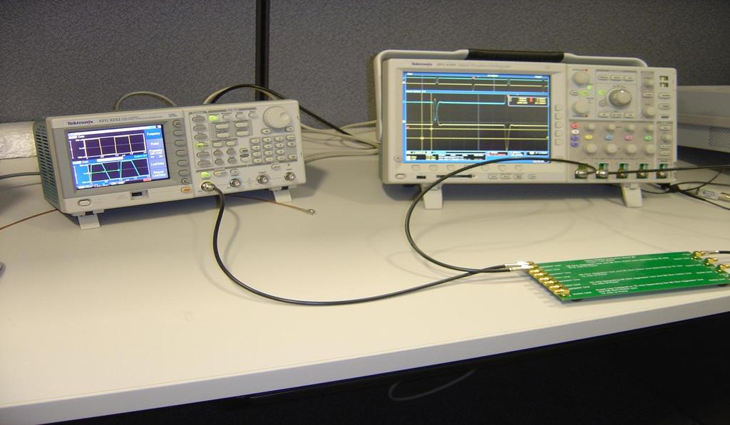
14 Experimental Set-Up 14
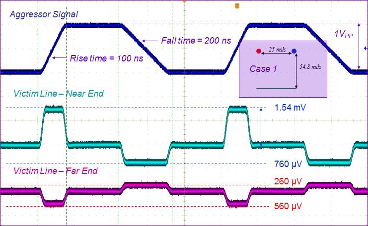
15 Case 1 15
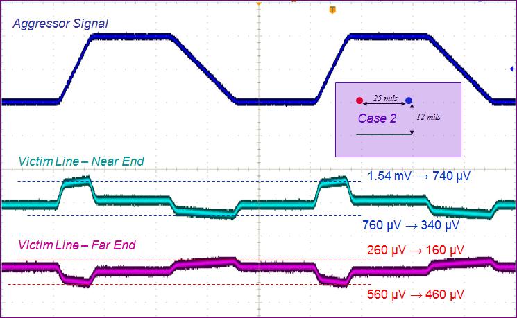
16 Case 2 16
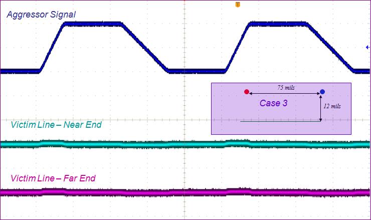
17 Case 3 17
18 Design Implications Induced crosstalk voltage is proportional to d/dt and board geometry. To reduce crosstalk: - Increase the rise and fall times - Move ground plane closer to the signal plane - Move signal traces in the signal plane farther apart 18
19 Crosstalk in Frequency Domain 1 jm S S inductivecoupling jcm S S capacitivecoupling 1 jm S jcm S S S inductivecoupling capacitivecoupling 19
20 Transfer Function esponse 1 jm S S inductivecoupling jcm S S capacitivecoupling jm S jcm S S S 1 inductivecoupling capacitivecoupling S S j j IND CAP M M jm IND CAP M M jm Crosstalk increases 20 db/decade. 20
21 Crosstalk at 1 MHz Case 1 21
22 Crosstalk at 10 MHz Case 1 22
23 eferences and Acknowledgements B. Adamczyk, J. Teune EMC Hardware Demonstration PCB Crosstalk 2008 IEEE International EMC Symposium, Detroit, MI Bill Spence and Pete ander Wel, Gentex Corp. Board Design C.. Paul, Introduction to Electromagnetic Compatibility, 2 nd Ed,, 2006 H. W. Ott, Electromagnetic Compatibility Engineering 2009 B. Adamczyk, ecture Notes, GSU,
24 Next EMC Chapter Meeting Wed, June 19, 2013 Dennis M. ewis Associate Technical Fellow, Boeing The Impact of Cables and Connectors on adio Frequency and Microwave Measurement Uncertainties More details at: 24
Common Impedance Coupling Effect on Video and Audio Circuitry. Prof. Bogdan Adamczyk Grand Valley State University
 Common Impedance Coupling Effect on Video and Audio Circuitry Prof. Bogdan Adamczyk rand Valley State University Outline 1. Signal ground (signal return path) 2. Objectives of grounding 3. Single- vs.
ECE 528 Understanding Power Quality
 ECE 528 Understanding Power Quality http://www.ece.uidaho.edu/ee/power/ece528/ Paul Ortmann portmann@uidaho.edu 208-733-7972 (voice) Lecture 41 1 Today Wiring for communications Decibels Coupling Avoiding
Verifying Simulation Results with Measurements. Scott Piper General Motors
 Verifying Simulation Results with Measurements Scott Piper General Motors EM Simulation Software Can be easy to justify the purchase of software packages even costing tens of thousands of dollars Upper
Keywords Signal Integrity, micro-strip, crosstalk, NEXT, FEXT.
 Volume 6, Issue 4, April 2016 ISSN: 2277 128X International Journal of Advanced Research in Computer Science and Software Engineering Research Paper Available online at: www.ijarcsse.com Effect of Vias
Suppression Techniques using X2Y as a Broadband EMI Filter IEEE International Symposium on EMC, Boston, MA
 Suppression Techniques using X2Y as a Broadband EMI Filter Jim Muccioli Tony Anthony Dave Anthony Dale Sanders X2Y Attenuators, LLC Erie, PA 16506-2972 www.x2y.com Email: x2y@x2y.com Bart Bouma Yageo/Phycomp
Objectives of transmission lines
 Introduction to Transmission Lines Applications Telephone Cable TV (CATV, or Community Antenna Television) Broadband network High frequency (RF) circuits, e.g., circuit board, RF circuits, etc. Microwave
Signal and Noise Measurement Techniques Using Magnetic Field Probes
 Signal and Noise Measurement Techniques Using Magnetic Field Probes Abstract: Magnetic loops have long been used by EMC personnel to sniff out sources of emissions in circuits and equipment. Additional
Investigation of Cavity Resonances in an Automobile
 Investigation of Cavity Resonances in an Automobile Haixiao Weng, Daryl G. Beetner, Todd H. Hubing, and Xiaopeng Dong Electromagnetic Compatibility Laboratory University of Missouri-Rolla Rolla, MO 65409,
Heat sink. Insulator. µp Package. Heatsink is shown with parasitic coupling.
 X2Y Heatsink EMI Reduction Solution Summary Many OEM s have EMI problems caused by fast switching gates of IC devices. For end products sold to consumers, products must meet FCC Class B regulations for
Chapter 12 Digital Circuit Radiation. Electromagnetic Compatibility Engineering. by Henry W. Ott
 Chapter 12 Digital Circuit Radiation Electromagnetic Compatibility Engineering by Henry W. Ott Forward Emission control should be treated as a design problem from the start, it should receive the necessary
Predicting and Controlling Common Mode Noise from High Speed Differential Signals
 Predicting and Controlling Common Mode Noise from High Speed Differential Signals Bruce Archambeault, Ph.D. IEEE Fellow, inarte Certified Master EMC Design Engineer, Missouri University of Science & Technology
Engineering the Power Delivery Network
 C HAPTER 1 Engineering the Power Delivery Network 1.1 What Is the Power Delivery Network (PDN) and Why Should I Care? The power delivery network consists of all the interconnects in the power supply path
AN IMPROVED MODEL FOR ESTIMATING RADIATED EMISSIONS FROM A PCB WITH ATTACHED CABLE
 Progress In Electromagnetics Research M, Vol. 33, 17 29, 2013 AN IMPROVED MODEL FOR ESTIMATING RADIATED EMISSIONS FROM A PCB WITH ATTACHED CABLE Jia-Haw Goh, Boon-Kuan Chung *, Eng-Hock Lim, and Sheng-Chyan
Long Range Connector Via Coupling Effects for High Speed Signals
 Long Range Connector Via Coupling Effects for High Speed Signals Dr. Roland Frech 2), Dr. Thomas Winkel 2), Dr. Thomas Gneiting 1) 1) AdMOS GmbH, 2) IBM Entwicklungs GmbH thomas.gneiting@admos.de Abstract
Simulation and Design of Printed Circuit Boards Utilizing Novel Embedded Capacitance Material
 Simulation and Design of Printed Circuit Boards Utilizing Novel Embedded Capacitance Material April 28, 2010 Yu Xuequan, Yanhang, Zhang Gezi, Wang Haisan Huawei Technologies CO., LTD. Shanghai, China Tony_yu@huawei.com
Crosstalk Coupling between Cable Pairs
 Crosstalk Coupling between Cable Pairs By: Mohammed M Al-Asadi and Alistair P. Duffy - De Montfort University, UK and Kenneth G Hodge, and Arthur J Willis - Brand-Rex Ltd, UK Abstract A new approach to
Ensuring Signal and Power Integrity for High-Speed Digital Systems
 Ensuring Signal and Power Integrity for High-Speed Digital Systems An EMC Perspective Christian Schuster Institut für Theoretische Elektrotechnik Technische Universität Hamburg-Harburg (TUHH) Invited Presentation
10 Safety earthing/grounding does not help EMC at RF
 1of 6 series Webinar #3 of 3, August 28, 2013 Grounding, Immunity, Overviews of Emissions and Immunity, and Crosstalk Contents of Webinar #3 Topics 1 through 9 were covered by the previous two webinars
Test and Measurement for EMC
 Test and Measurement for EMC Bogdan Adamczyk, Ph.D., in.c.e. Professor of Engineering Director of the Electromagnetic Compatibility Center Grand Valley State University, Michigan, USA Ottawa, Canada July
TECHNICAL REPORT: CVEL Maximum Radiated Emission Calculator: Common-mode EMI Algorithm. Chentian Zhu and Dr. Todd Hubing. Clemson University
 TECHNICAL REPORT: CVEL-13-051 Maximum Radiated Emission Calculator: Common-mode EMI Algorithm Chentian Zhu and Dr. Todd Hubing Clemson University December 23, 2013 Table of Contents Abstract... 3 1. Introduction...
Chapter 16 PCB Layout and Stackup
 Chapter 16 PCB Layout and Stackup Electromagnetic Compatibility Engineering by Henry W. Ott Foreword The PCB represents the physical implementation of the schematic. The proper design and layout of a printed
Experimental Investigation of High-Speed Digital Circuit s Return Current on Electromagnetic Emission
 Proceedings of MUCEET2009 Malaysian Technical Universities Conference on Engineering and Technology June 20-22, 2009, MS Garden,Kuantan, Pahang, Malaysia MUCEET2009 Experimental Investigation of High-Speed
Design for EMI & ESD compliance DESIGN FOR EMI & ESD COMPLIANCE
 DESIGN FOR EMI & ESD COMPLIANCE All of we know the causes & impacts of EMI & ESD on our boards & also on our final product. In this article, we will discuss some useful design procedures that can be followed
VLSI is scaling faster than number of interface pins
 High Speed Digital Signals Why Study High Speed Digital Signals Speeds of processors and signaling Doubled with last few years Already at 1-3 GHz microprocessors Early stages of terahertz Higher speeds
150Hz to 1MHz magnetic field coupling to a typical shielded cable above a ground plane configuration
 150Hz to 1MHz magnetic field coupling to a typical shielded cable above a ground plane configuration D. A. Weston Lowfreqcablecoupling.doc 7-9-2005 The data and information contained within this report
MEASUREMENTS OF COUPLING THROUGH BRAIDED SHIELD VIA NEW CONDUCTED IMMUNITY TECH- NIQUE
 Progress In Electromagnetics Research C, Vol. 11, 61 68, 2009 MEASUREMENTS OF COUPLING THROUGH BRAIDED SHIELD VIA NEW CONDUCTED IMMUNITY TECH- NIQUE M. Ghassempouri College of Electrical Engineering Iran
Understanding the Unintended Antenna Behavior of a Product
 Understanding the Unintended Antenna Behavior of a Product Colin E. Brench Southwest Research Institute Electromagnetic Compatibility Research and Testing colin.brench@swri.org Radiating System Source
ELECTROMAGNETIC COMPATIBILITY HANDBOOK 1. Chapter 8: Cable Modeling
 ELECTROMAGNETIC COMPATIBILITY HANDBOOK 1 Chapter 8: Cable Modeling Related to the topic in section 8.14, sometimes when an RF transmitter is connected to an unbalanced antenna fed against earth ground
An Analysis of the Fields on the Horizontal Coupling Plane in ESD testing
 An Analysis of the Fields on the Horizontal Coupling Plane in ESD testing Stephan Frei David Pommerenke Technical University Berlin, Einsteinufer 11, 10597 Berlin, Germany Hewlett Packard, 8000 Foothills
Investigation of a Voltage Probe in Microstrip Technology
 Investigation of a Voltage Probe in Microstrip Technology (Specifically in 7-tesla MRI System) By : Mona ParsaMoghadam Supervisor : Prof. Dr. Ing- Klaus Solbach April 2015 Introduction - Thesis work scope
External Drive Hardware
 US1086e_External Drive Hardware, 08/2010 External Drive Hardware Selection and Application Answers Answers to external hardware questions A soup to nuts list of questions with installation / application
PCB Design Guidelines for Reduced EMI
 PCB Design Guidelines for Reduced EMI Guided By: Prof. Ruchi Gajjar Prepared By: Shukla Jay (13MECE17) Outline Power Distribution for Two-Layer Boards Gridding Power Traces on Two-Layer Boards Ferrite
Alternative Coupling Method for Immunity Testing of Power Grid Protection Equipment
 Alternative Coupling Method for Immunity Testing of Power Grid Protection Equipment Christian Suttner*, Stefan Tenbohlen Institute of Power Transmission and High Voltage Technology (IEH), University of
Todd H. Hubing Michelin Professor of Vehicular Electronics Clemson University
 Essential New Tools for EMC Diagnostics and Testing Todd H. Hubing Michelin Professor of Vehicular Electronics Clemson University Where is Clemson University? Clemson, South Carolina, USA Santa Clara Valley
EM Noise Mitigation in Electronic Circuit Boards and Enclosures
 EM Noise Mitigation in Electronic Circuit Boards and Enclosures Omar M. Ramahi, Lin Li, Xin Wu, Vijaya Chebolu, Vinay Subramanian, Telesphor Kamgaing, Tom Antonsen, Ed Ott, and Steve Anlage A. James Clark
An Investigation of the Effect of Chassis Connections on Radiated EMI from PCBs
 An Investigation of the Effect of Chassis Connections on Radiated EMI from PCBs N. Kobayashi and T. Harada Jisso and Production Technologies Research Laboratories NEC Corporation Sagamihara City, Japan
Technology in Balance
 Technology in Balance A G1 G2 B Basic Structure Comparison Regular capacitors have two plates or electrodes surrounded by a dielectric material. There is capacitance between the two conductive plates within
Frequently Asked EMC Questions (and Answers)
") Frequently Asked EMC Questions (and Answers) Elya B. Joffe President Elect IEEE EMC Society e-mail: eb.joffe@ieee.org December 2, 2006 1 I think I know what the problem is 2 Top 10 EMC Questions 10, 9
Frequently Asked EMC Questions (and Answers) Elya B. Joffe President Elect IEEE EMC Society e-mail: eb.joffe@ieee.org December 2, 2006 1 I think I know what the problem is 2 Top 10 EMC Questions 10, 9
How the Braid Impedance of Instrumentation Cables Impact PI and SI Measurements
 How the Braid Impedance of Instrumentation Cables Impact PI and SI Measurements Istvan Novak (*), Jim Nadolny (*), Gary Biddle (*), Ethan Koether (**), Brandon Wong (*) (*) Samtec, (**) Oracle This session
FDTD and Experimental Investigation of EMI from Stacked-Card PCB Configurations
 IEEE TRANSACTIONS ON ELECTROMAGNETIC COMPATABILITY, VOL. 43, NO. 1, FEBRUARY 2001 1 FDTD and Experimental Investigation of EMI from Stacked-Card PCB Configurations David M. Hockanson, Member, IEEE, Xiaoning
Internal Model of X2Y Chip Technology
 Internal Model of X2Y Chip Technology Summary At high frequencies, traditional discrete components are significantly limited in performance by their parasitics, which are inherent in the design. For example,
Analysis of a PCB-Chassis System Including Different Sizes of Multiple Planes Based on SPICE
 Analysis of a PCB-Chassis System Including Different Sizes of Multiple Planes Based on SPICE Naoki Kobayashi (1), Todd Hubing (2) and Takashi Harada (1) (1) NEC, System Jisso Research Laboratories, Kanagawa,
Solutions for EMC Issues in Automotive System Transmission Lines
 June 23, 2010 Solutions for EMC Issues in Automotive System Transmission Lines FTF-ENT-F0174 Todd Hubing Clemson University and VortiQa are trademarks of Freescale Semiconductor, Inc. All other product
Optimization of Wafer Level Test Hardware using Signal Integrity Simulation
 June 7-10, 2009 San Diego, CA Optimization of Wafer Level Test Hardware using Signal Integrity Simulation Jason Mroczkowski Ryan Satrom Agenda Industry Drivers Wafer Scale Test Interface Simulation Simulation
EMC cases study. Antonio Ciccomancini Scogna, CST of America CST COMPUTER SIMULATION TECHNOLOGY
 EMC cases study Antonio Ciccomancini Scogna, CST of America antonio.ciccomancini@cst.com Introduction Legal Compliance with EMC Standards without compliance products can not be released to the market Failure
Comparison of IC Conducted Emission Measurement Methods
 IEEE TRANSACTIONS ON INSTRUMENTATION AND MEASUREMENT, VOL. 52, NO. 3, JUNE 2003 839 Comparison of IC Conducted Emission Measurement Methods Franco Fiori, Member, IEEE, and Francesco Musolino, Member, IEEE
BIRD 74 - recap. April 7, Minor revisions Jan. 22, 2009
 BIRD 74 - recap April 7, 2003 Minor revisions Jan. 22, 2009 Please direct comments, questions to the author listed below: Guy de Burgh, EM Integrity mail to: gdeburgh@nc.rr.com (919) 457-6050 Copyright
Freescale Semiconductor, I
 Order this document by /D Noise Reduction Techniques for Microcontroller-Based Systems By Imad Kobeissi Introduction With today s advancements in semiconductor technology and the push toward faster microcontroller
High-speed Serial Interface
 High-speed Serial Interface Lect. 9 Noises 1 Block diagram Where are we today? Serializer Tx Driver Channel Rx Equalizer Sampler Deserializer PLL Clock Recovery Tx Rx 2 Sampling in Rx Interface applications
Cross Coupling Between Power and Signal Traces on Printed Circuit Boards
 Cross Coupling Between Power and Signal Traces on Printed Circuit Boards Dr. Zorica Pantic-Tanner Edwin Salgado Franz Gisin San Francisco State University Silicon Graphics Inc. Silicon Graphics Inc. 1600
Test Results #TR 4012, v1.0
 ITT Industries, Electronic Components/X2Y Attenuators Case Study of Filtered Connector Application in Blower Motor to Meet EMC Requirements Test Results #TR 4012, v1.0 DISCLAIMER: Information and suggestions
PROTECTING SIGNALS FROM EMI - CROSSTALK ANALYSIS. Snežana ČUNDEVA 1
 Invited paper POTECTING SIGNALS FOM EMI - COSSTALK ANALYSIS Snežana ČUNDEVA 1 Abstract: The paper treats a very important aspect of the design of an electromagnetically compatible product - the crosstalk.
Designing Your EMI Filter
 The Engineer s Guide to Designing Your EMI Filter TABLE OF CONTENTS Introduction Filter Classifications Why Do We Need EMI Filters Filter Configurations 2 2 3 3 How to Determine Which Configuration to
Digital Systems Power, Speed and Packages II CMPE 650
 Speed VLSI focuses on propagation delay, in contrast to digital systems design which focuses on switching time: A B A B rise time propagation delay Faster switching times introduce problems independent
Reconstruction of Current Distribution and Termination Impedances of PCB-Traces by Magnetic Near-Field Data and Transmission-Line Theory
 Reconstruction of Current Distribution and Termination Impedances of PCB-Traces by Magnetic Near-Field Data and Transmission-Line Theory Robert Nowak, Stephan Frei TU Dortmund University Dortmund, Germany
3d System Integration Simulation
 3d System Integration Simulation Dr. Thomas Fischer Siemens Audiology Solutions fischerthomas@siemens.com CST Usergroup Conference, May 2012 T. Fischer, CST User Conference 2012, Page 1 Copyright Siemens
Applications of 3D Electromagnetic Modeling in Magnetic Recording: ESD and Signal Integrity
 Applications of 3D Electromagnetic Modeling in Magnetic Recording: ESD and Signal Integrity CST NORTH AMERICAN USERS FORUM John Contreras 1 and Al Wallash 2 Hitachi Global Storage Technologies 1. San Jose
Use and abuse of screened cables
 December 2016 Use and abuse of screened cables Tim Williams Elmac Services 1 of 21 Outline How does a screened cable work? electric fields, magnetic fields, low versus high frequency Types of screen Transfer
Investigation of Electromagnetic Field Coupling from DC-DC Buck Converters to Automobile AM/FM Antennas
 CST North American Automotive Workshop Investigation of Electromagnetic Field Coupling from DC-DC Buck Converters to Automobile AM/FM Antennas Patrick DeRoy, CST of America, Framingham, Massachusetts,
Understanding and Optimizing Electromagnetic Compatibility in Switchmode Power Supplies
 Understanding and Optimizing Electromagnetic Compatibility in Switchmode Power Supplies 1 Definitions EMI = Electro Magnetic Interference EMC = Electro Magnetic Compatibility (No EMI) Three Components
Transfer Functions in EMC Shielding Design
 Transfer Functions in EMC Shielding Design Transfer Functions Definition Overview of Theory Shielding Effectiveness Definition & Test Anomalies George Kunkel CEO, Spira Manufacturing Corporation www.spira-emi.com
TECHNICAL REPORT: CVEL Investigation of the Imbalance Difference Model and its Application to Various Circuit Board and Cable Geometries
 TECHNICAL REPORT: CVEL-0-07.0 Investigation of the Imbalance Difference Model and its Application to Various Circuit Board and Cable Geometries Hocheol Kwak and Dr. Todd Hubing Clemson University May.
Using TEM Cell Measurements to Estimate the Maximum Radiation From PCBs With Cables Due to Magnetic Field Coupling
 IEEE TRANSACTIONS ON ELECTROMAGNETIC COMPATIBILITY, VOL. 50, NO. 2, MAY 2008 419 from TEM mode to higher order modes is not affected. Thus, the energy converted from TEM mode to higher order modes is still
"Natural" Antennas. Mr. Robert Marcus, PE, NCE Dr. Bruce C. Gabrielson, NCE. Security Engineering Services, Inc. PO Box 550 Chesapeake Beach, MD 20732
 Published and presented: AFCEA TEMPEST Training Course, Burke, VA, 1992 Introduction "Natural" Antennas Mr. Robert Marcus, PE, NCE Dr. Bruce C. Gabrielson, NCE Security Engineering Services, Inc. PO Box
ELECTROMAGNETIC SHIELDING HANDBOOK FOR WIRED AND WIRELESS EMC APPLICATIONS
 ELECTROMAGNETIC SHIELDING HANDBOOK FOR WIRED AND WIRELESS EMC APPLICATIONS by Anatoly Tsaliovich Kluwer Academic Publishers Boston / London / Dordrecht Contents Foreword Preface xiii xvii 1. INTRODUCTION
Common myths, fallacies and misconceptions in Electromagnetic Compatibility and their correction.
 Common myths, fallacies and misconceptions in Electromagnetic Compatibility and their correction. D. A. Weston EMC Consulting Inc 22-3-2010 These are some of the commonly held beliefs about EMC which are
Analysis of Laddering Wave in Double Layer Serpentine Delay Line
 International Journal of Applied Science and Engineering 2008. 6, 1: 47-52 Analysis of Laddering Wave in Double Layer Serpentine Delay Line Fang-Lin Chao * Chaoyang University of Technology Taichung, Taiwan
Todd Hubing. Clemson University. Cabin Environment Communication System. Controls Airbag Entertainment Systems Deployment
 Automotive Component Measurements for Determining Vehicle-Level Radiated Emissions Todd Hubing Michelin Professor of Vehicular Electronics Clemson University Automobiles are Complex Electronic Systems
EMI AND BEL MAGNETIC ICM
 EMI AND BEL MAGNETIC ICM ABSTRACT Electromagnetic interference (EMI) in a local area network (LAN) system is a common problem that every LAN system designer faces, and it is a growing problem because the
Signal Integrity, Part 1 of 3
 by Barry Olney feature column BEYOND DESIGN Signal Integrity, Part 1 of 3 As system performance increases, the PCB designer s challenges become more complex. The impact of lower core voltages, high frequencies
Understanding Electromagnetic Effects using Printed Circuit Board Demos Frits Buesink, Frank Leferink 1,2
 Understanding Electromagnetic Effects using Printed Circuit Board Demos Frits Buesink, Frank Leferink 1,2 1 University of Twente, P.O. Box 217, 75 AE Enschede, The Netherlands 2 THALES, P.O. Box 42, 755
Measurement of Laddering Wave in Lossy Serpentine Delay Line
 International Journal of Applied Science and Engineering 2006.4, 3: 291-295 Measurement of Laddering Wave in Lossy Serpentine Delay Line Fang-Lin Chao * Department of industrial Design, Chaoyang University
AN1705. Motorola Semiconductor Application Note. Noise Reduction Techniques for Microcontroller-Based Systems. Introduction
 Order this document by /D Motorola Semiconductor Application Note Noise Reduction Techniques for Microcontroller-Based Systems By Imad Kobeissi Introduction With today s advancements in semiconductor technology
LISN UP Application Note
 LISN UP Application Note What is the LISN UP? The LISN UP is a passive device that enables the EMC Engineer to easily distinguish between differential mode noise and common mode noise. This will enable
Resonance Analysis Focusing on Stray Inductance and Capacitance of Laminated Bus Bars
 IEEJ Journal of Industry Applications Vol.5 No.6 pp.407 42 DOI: 0.54/ieejjia.5.407 Paper Resonance Analysis Focusing on Stray Inductance and Capacitance of Laminated Bus Bars Akihiro Hino Member, Keiji
Modeling and Practical Suggestions to Improve ESD Immunity Test Repeatability
 17 th Symposium IMEKO TC, 3 rd Symposium IMEKO TC 19 and 15 th IWDC Workshop Sept. -1, 1, Kosice, Slovakia Modeling and Practical Suggestions to Improve ESD Immunity Test Repeatability. Morando 1, M. Borsero,.
A Complete Simulation of a Radiated Emission Test according to IEC
 34 PIERS Proceedings, August 27-30, Prague, Czech Republic, 2007 A Complete Simulation of a Radiated Emission Test according to IEC 61000-4-20 X. T. I Ngu, A. Nothofer, D. W. P. Thomas, and C. Christopoulos
Technical Report Printed Circuit Board Decoupling Capacitor Performance For Optimum EMC Design
 Technical Report Printed Circuit Board Decoupling Capacitor Performance For Optimum EMC Design Bruce Archambeault, Ph.D. Doug White Personal Systems Group Electromagnetic Compatibility Center of Competency
TECHNICAL REPORT: CVEL Parasitic Inductance Cancellation for Filtering to Chassis Ground Using Surface Mount Capacitors
 TECHNICAL REPORT: CVEL-14-059 Parasitic Inductance Cancellation for Filtering to Chassis Ground Using Surface Mount Capacitors Andrew J. McDowell and Dr. Todd H. Hubing Clemson University April 30, 2014
Chapter 12: Transmission Lines. EET-223: RF Communication Circuits Walter Lara
 Chapter 12: Transmission Lines EET-223: RF Communication Circuits Walter Lara Introduction A transmission line can be defined as the conductive connections between system elements that carry signal power.
EE 521: Instrumentation and Measurements
 Aly El-Osery Electrical Engineering Department, New Mexico Tech Socorro, New Mexico, USA October 18, 2009 1 / 18 1 Sources of Coherent Interference Capacitive Coupling Inductive Coupling Ground Loops Power
3 GHz Wide Frequency Model of Surface Mount Technology (SMT) Ferrite Bead for Power/Ground and I/O Line Noise Simulation of High-speed PCB
 Ferrite Bead for Power/Ground and I/O Line Noise Simulation of High-speed PCB") 3 GHz Wide Frequency Model of Surface Mount Technology (SMT) Ferrite Bead for Power/Ground and I/O Line Noise Simulation of High-speed PCB Tae Hong Kim, Hyungsoo Kim, Jun So Pak, and Joungho Kim Terahertz
3 GHz Wide Frequency Model of Surface Mount Technology (SMT) Ferrite Bead for Power/Ground and I/O Line Noise Simulation of High-speed PCB Tae Hong Kim, Hyungsoo Kim, Jun So Pak, and Joungho Kim Terahertz
Non-Ideal Behavior of Components
 Non-Ideal Behavior of Components Todd H. Hubing Dept. of Electrical and Computer Engineering Clemson, University Clemson, SC 29634 USA email: hubing@clemson.edu Telephone: 1-864-656-7219 Circuit Schematics
EFFECT OF INTEGRATION ERROR ON PARTIAL DISCHARGE MEASUREMENTS ON CAST RESIN TRANSFORMERS. C. Ceretta, R. Gobbo, G. Pesavento
 Sept. 22-24, 28, Florence, Italy EFFECT OF INTEGRATION ERROR ON PARTIAL DISCHARGE MEASUREMENTS ON CAST RESIN TRANSFORMERS C. Ceretta, R. Gobbo, G. Pesavento Dept. of Electrical Engineering University of
Modeling of Power Planes for Improving EMC in High Speed Medical System
 Modeling of Power Planes for Improving EMC in High Speed Medical System Surender Singh, Dr. Ravinder Agarwal* *Prof : Dept of Instrumentation Engineering Thapar University, Patiala, India Dr. V. R. Singh
Heat Sink Design Flow for EMC
 DesignCon 2008 Heat Sink Design Flow for EMC Philippe Sochoux, Cisco Systems, Inc. psochoux@cisco.com Jinghan Yu, Cisco Systems, Inc. jinyu@cisco.com Alpesh U. Bhobe, Cisco Systems, Inc. abhobe@cisco.com
Resonant EBG-Based Common Mode Filter for LTCC Substrates
 UAq EMC Laboratory Resonant EBG-Based Common Mode Filter for LTCC Substrates C. Olivieri, F. De Paulis, A. Orlandi S. Connor, B.Archambeault UAq EMC Laboratory, University of L'Aquila, L'Aquila, Italy
Anthony A. Anthony X2Y Attenuators, LLC 2700 West 21 st. Street, Suite 11 Erie, PA , USA
 Published in ITEM TM 2 Issue Page 12 by Robar Industries April 17, 2 Dynamic Testing Of A Dual Line Filter For Common And Differential Mode Attenuation using a Spectrum Analyzer James P. Muccioli, IEEE-Fellow
A review of shielding performance By Albert R. Martin
 A review of shielding performance By Albert R. Martin INTRODUCTION What determines how effective a cable shield is going to be? And how does the decision to ground or not ground a shield impact its effectiveness?
MINIMIZING EMI EFFECTS DURING PCB LAYOUT OF Z8/Z8PLUS CIRCUITS
 APPLICATION NOTE MINIMIZING EMI EFFECTS DURING PCB LAYOUT OF Z8/Z8PLUS CIRCUITS INTRODUCTION The Z8/Z8Plus families have redefined ease-of-use by being the simplest 8-bit microcontrollers to program. Combined
EMI. Chris Herrick. Applications Engineer
 Fundamentals of EMI Chris Herrick Ansoft Applications Engineer Three Basic Elements of EMC Conduction Coupling process EMI source Emission Space & Field Conductive Capacitive Inductive Radiative Low, Middle
Debugging EMI Using a Digital Oscilloscope. Dave Rishavy Product Manager - Oscilloscopes
 Debugging EMI Using a Digital Oscilloscope Dave Rishavy Product Manager - Oscilloscopes 06/2009 Nov 2010 Fundamentals Scope Seminar of DSOs Signal Fidelity 1 1 1 Debugging EMI Using a Digital Oscilloscope
Electromagnetic Compatibility
 Electromagnetic Compatibility Introduction to EMC International Standards Measurement Setups Emissions Applications for Switch-Mode Power Supplies Filters 1 What is EMC? A system is electromagnetic compatible
Advanced Topics in EMC Design. Issue 1: The ground plane to split or not to split?
 NEEDS 2006 workshop Advanced Topics in EMC Design Tim Williams Elmac Services C o n s u l t a n c y a n d t r a i n i n g i n e l e c t r o m a g n e t i c c o m p a t i b i l i t y e-mail timw@elmac.co.uk
EMC review for Belle II (Grounding & shielding plans) PXD DEPFET system
 PXD DEPFET system") EMC review for Belle II (Grounding & shielding plans) PXD DEPFET system Outline 1. Introduction 2. Grounding strategy Implementation aspects 3. Noise emission issues Test plans 4. Noise immunity issues
EMC review for Belle II (Grounding & shielding plans) PXD DEPFET system Outline 1. Introduction 2. Grounding strategy Implementation aspects 3. Noise emission issues Test plans 4. Noise immunity issues
Class-D Audio Power Amplifiers: PCB Layout For Audio Quality, EMC & Thermal Success (Home Entertainment Devices)
") Class-D Audio Power Amplifiers: PCB Layout For Audio Quality, EMC & Thermal Success (Home Entertainment Devices) Stephen Crump http://e2e.ti.com Audio Power Amplifier Applications Audio and Imaging Products
Class-D Audio Power Amplifiers: PCB Layout For Audio Quality, EMC & Thermal Success (Home Entertainment Devices) Stephen Crump http://e2e.ti.com Audio Power Amplifier Applications Audio and Imaging Products
WE05MF. 2 SOT-553 (Top View) Features IEC COMPATIBILITY (EN ) Tel: Transient Voltage Suppressor SOT-553
 Features IEC COMPATIBILITY (EN ) Tel: Transient Voltage Suppressor SOT-553") Document: W030044, Rev: A Transient Voltage Suppressor Features Solid-state silicon-avalanche technology 30 Watts Peak Pulse Power per Line (t p =8/20μs) Low operating and clamping voltages Up to Four
Document: W030044, Rev: A Transient Voltage Suppressor Features Solid-state silicon-avalanche technology 30 Watts Peak Pulse Power per Line (t p =8/20μs) Low operating and clamping voltages Up to Four
Electrical Characterization of a 64 Ball Grid Array Package
 EMC Europe - Hamburg, 8 th September 008 Summary Electrical Characterization of a 64 Ball Grid Array A. Boyer (), E. Sicard (), M. Fer (), L. Courau () () LATTIS - INSA of Toulouse - France () ST-Microelectronics
OPEN SOURCE CABLE MODELS FOR EMI SIMULATIONS
 OPEN SOURCE CABLE MODELS FOR EMI SIMULATIONS S. Greedy 1, C. Smartt 1, D. W. P. Thomas 1. 1 : George Green Institute for Electromagnetics Research, Department of Electrical and Electronic Engineering,
Modelling electromagnetic field coupling from an ESD gun to an IC
 Modelling electromagnetic field coupling from an ESD gun to an IC Ji Zhang #1, Daryl G Beetner #2, Richard Moseley *3, Scott Herrin *4 and David Pommerenke #5 # EMC Laboratory, Missouri University of Science