Advanced Measurements
|
|
|
- Raymond Hensley
- 6 years ago
- Views:
Transcription

1 Albaha University Faculty of Engineering Mechanical Engineering Department Lecture 5: Displacement measurement Ossama Abouelatta Mechanical Engineering Department Faculty of Engineering Albaha University 2012 Aims This lecture aims: This lecture first reviews the state of sensor technology for manufacturing process monitoring in general. Methods of measuring pressure Electrical pressure measuring equipment Strain gauge and pressure transducers General information Principle of piezo-electric sensors Absolute and differential pressure sensors Experiment - Absolute pressure sensor.. Assoc. Prof. Ossama Abouelatta, Mechanical Engineering Department, Faculty of Engineering, Albaha University (2)
2 Outline Introduction Absolute sensors Principle of inductive sensors Design of inductive sensors Functioning of a differential inductor Inductive proximity sensors Inductive proximity switch 'Inductive displacement sensor' card SO4203-5U General Principle of inductive sensors Experiments - Inductive displacement Zero-point calibration of the measuring bridge Assoc. Prof. Ossama Abouelatta, Mechanical Engineering Department, Faculty of Engineering, Albaha University (3) Introduction In the sphere of electrical instrumentation, a distinction is made between analog and digital measuring techniques. An analog technique is when a display method is used that shows the value continuously. A digital technique is one where the measured variable is detected in a quantized form with a discrete minimum resolution. Frequent characteristics of digital methods are a numerical procedure or a coded enumeration of the measured values. Familiar examples of these two differing techniques are the speed sensors (speedometers) or distance measuring devices (odometers) in cars. To measure variables, appropriate sensors are required to provide an analog or digital electrical signal. The nature of the signal can be changed from one kind to another by means of analog-to-digital or digital-to-analog converters. Assoc. Prof. Ossama Abouelatta, Mechanical Engineering Department, Faculty of Engineering, Albaha University (4)
 or in combination with strain gauges.")
3 Introduction Displacement and angle sensors are suitable for measuring distance, length, position and angle of rotation. Analog versions are mainly used as passive resistance sensors with potentiometers (e.g. with face-plate or helical structures) or in combination with strain gauges. They may also be manufactured as inductive sensors. Inductive immersion armature measuring system for oil-based hydraulics Assoc. Prof. Ossama Abouelatta, Mechanical Engineering Department, Faculty of Engineering, Albaha University (5) Introduction For industrial measurement of displacement or angle analog sensors are very often used in spite of the modern trend towards digitalization. This is always the case when continuous resolution is essential or when transitions in the signal need to be continuous rather than occurring in steps, for example. Usually such sensors operate without contact using optical, inductive or magnetic measurement techniques. The inductive and magnetic systems are usually enormously superior to optical systems in terms of robustness and resistance to dirt. In industry the trends are leading increasingly towards digital processing of measurements. This means that either a measuring system that intrinsically provides a digital signal must be used or an analog-to-digital converter is needed to simply convert analog signals into digital form. Assoc. Prof. Ossama Abouelatta, Mechanical Engineering Department, Faculty of Engineering, Albaha University (6)
4 Introduction The group of analog sensors, includingsine and cosine potentiometers, continues to play a key role alongside purely digital methods since it is easy to digitalize the signals from them. Digital displacement and angle converters include incremental sensors that, although they may be built on the basis of resistive or inductive sensors, may also involve electrodynamics and electro-optical devices. Quantizing the sensor can be a means of generating a discontinuous or discrete signal from the initial analog signal. Each of the elements, i.e. quantized displacement unit, produces a pulse that can be input to a counter. The counter status represents the measured displacement. These two steps, quantization and counter display characterize the incremental method as a digital sensor technique. Assoc. Prof. Ossama Abouelatta, Mechanical Engineering Department, Faculty of Engineering, Albaha University (7) Introduction a) Fine-wire rotary voltage divider b) Curved disc d) Toothed disc with passive inductive (left) or active electrodynamics measuring technique (right). e) Perforated or slotted disc with photo-electric measuring technique α) Angle of rotation a) b) Speed and angle transducer c) d) e) Analog systems with characteristic f) Digital systems with logic analyzer trace Assoc. Prof. Ossama Abouelatta, Mechanical Engineering Department, Faculty of Engineering, Albaha University (8)
5 Introduction The disadvantage of the simple technique is obvious. Since each individual value is dependent on the previous one, any faulty reading means that all subsequent results are erroneous. In the event of a power failure the current measured value is lost entirely. A relative technique of this kind does, however, have the advantage that its zero point can easily be set to be at any point. For example, in order to detect the direction of motion using positional methods, incremental methods require two sensors separated by half of one quantization unit, the signals from which can then be evaluated by a logical network before being fed to an up/down counter. It is not sufficient to detect the static signal from each track of the pattern and to link them together, but the edges where the signal changes (e.g. light-dark transitions of elements) must also be detected. This requires quite a complicated circuit. Assoc. Prof. Ossama Abouelatta, Mechanical Engineering Department, Faculty of Engineering, Albaha University (9) Introduction Further refinements such as reference marks on a third track of the quantized pattern, enable an immediate and well-defined usage of the counter after a power failure. With special opto-electronic systems errors can even be detected by means of external disturbance pulses or by the loss of certain pattern markings. (Moiré strip technique). Electro-optical methods have become widespread due their lack of wearing components being entirely contactless and due to their relative lack of susceptibility to electrical interference. There are versions where the light passes right through the components (transmission) or others where light is reflected (reflection). This applies to both incremental and absolute sensors. Assoc. Prof. Ossama Abouelatta, Mechanical Engineering Department, Faculty of Engineering, Albaha University (10)
6 Absolute sensors For sensors detecting absolute displacement,the entiremeasuringrangeneeds to be divided into discrete, numbered, quantized regions - as for all digital methods. In contrast to incremental methods, these quantized regions are not simply counted by are all provided with unique markings, e.g. by means of distinct quantized codes of a ruler. These markings and thus each position correspond to a distinct and fixed numeric value. The practical display of these numbers is achieved by means of suitable coding. Absolute displacement and angle sensors are thus called decoded displacement sensors (encoders). Typical applications include digital displacement and angle sensors used for numerically controlled tools (NC or CNC). Incremental systems currently cover about 80% of this market. Assoc. Prof. Ossama Abouelatta, Mechanical Engineering Department, Faculty of Engineering, Albaha University (11) Absolute sensors Position sensing for machine control a) Direct measurement of position b) Indirect measurement of position Assoc. Prof. Ossama Abouelatta, Mechanical Engineering Department, Faculty of Engineering, Albaha University (12)
 Principle of inductive")


. The change in inductance can be detected using a suitable measuring bridge.")
7 Absolute sensors Incremental measurement of position Absolute measurement of position Assoc. Prof. Ossama Abouelatta, Mechanical Engineering Department, Faculty of Engineering, Albaha University (13) Principle of inductive sensors Design of inductive sensors Inductive sensors usually consist of one or more coils with variable inductance. The figure to the above-right shows an example of a cylindrical coil and the formula for determining its inductance L, where l is the length of the coil, A is the surface area of the coil, N is the number of windings μ 0 is the field constant and μ r is the relative permeability of the medium inside the oil. The principle of the sensor involves the influence that the quantity to be measured (distance or displacement) has over the inductance of the coil(s). The change in inductance can be detected using a suitable measuring bridge. Industrial displacement sensor for the range mm Assoc. Prof. Ossama Abouelatta, Mechanical Engineering Department, Faculty of Engineering, Albaha University (14)

 Principle of inductive sensors Functioning of a differential inductor The")

8 Principle of inductive sensors Functioning of a differential inductor The following animation shows how a so-called differential inductor for displacement measurement works. Two identical coils L 1 und L 2 are located within a cylindrical housing. The core of the coil is a armature that moves along the axis and detects the displacement. When the armature moves, the permeability of its material causes the inductance of one coil to increase while the inductance of the other decreases by the same amount. Assoc. Prof. Ossama Abouelatta, Mechanical Engineering Department, Faculty of Engineering, Albaha University (15) Principle of inductive sensors Functioning of a differential inductor The following graphic shows the measuring circuit used. The circuit is supplied with an AC voltage U ~. The resistors R 1 and R 2 form a full bridge along with the two inductors. The measured voltage U M is then directly proportional to the displacement of the armature. Assoc. Prof. Ossama Abouelatta, Mechanical Engineering Department, Faculty of Engineering, Albaha University (16)
. The principle of this type of sensor involves the degree of damping by the detected object of a magnetic field produced by an oscillator.")

9 Principle of inductive sensors Inductive proximity sensors Inductive proximity sensors detect the distance between the sensor and an approaching object and can be used for distance measurement or for metal detectors, for example (see right). The principle of this type of sensor involves the degree of damping by the detected object of a magnetic field produced by an oscillator. The object must therefore be made of conducting material. The operating range is usually no more than a few millimeters. The animation alongside illustrates the principle of an inductive proximity sensor. The magnetic field produced by the oscillator spreads into the surrounding space due to the open shell core. If an object made of conducting material comes within the field, eddy currents are induced within it that result in damping of the field due to the law of induction and therefore to a reduction in the amplitude of the voltage. The voltage amplitude is therefore a measure of the distance between the object and the sensor. Assoc. Prof. Ossama Abouelatta, Mechanical Engineering Department, Faculty of Engineering, Albaha University (17) Principle of inductive sensors Inductive proximity switch The inductive proximity sensor described above can easily be used as a proximity switch (proximity initiator), where the voltage amplitude is processed via a Schmitt trigger. This is configured so that the switch goes "on" or "off" when the distance between the sensor and the object is below a certain threshold, which can be calibrated. Assoc. Prof. Ossama Abouelatta, Mechanical Engineering Department, Faculty of Engineering, Albaha University (18)
10 'Inductive displacement sensor' card SO4203-5U Assoc. Prof. Ossama Abouelatta, Mechanical Engineering Department, Faculty of Engineering, Albaha University (19) General The UNI-TRAIN Inductive displacement sensor card contains an inductive displacement sensor in the form of a differential inductor and the appropriate circuit. Displacementisdetectedbythemotionofanironcore inside the inductor coils. The motion causes the two inductances L 1 and L 2 to change, which can be detected by means of an AC powered measuring bridge. The circuit for an inductive displacement sensor. Assoc. Prof. Ossama Abouelatta, Mechanical Engineering Department, Faculty of Engineering, Albaha University (20)
 powered by relatively high frequency AC voltage.")
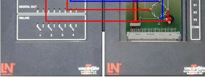
11 Principle of inductive sensors The sensor consists of a differential inductor with movable iron core. A voltage u D is generated via a measuring bridge (1) powered by relatively high frequency AC voltage. The amplitude and phase of the voltage (either 0 odder 180 ) depends on the position of the iron core. The null point of the bridge can be calibrated by means of potentiometer R 2. The bridge voltage is converted by a differential amplifier (2) into ground referenced voltage. The output of the differential amplifier is tapped via a 2-mm socket. The AC voltage measured is converted into DC by means of a sample-and-hold circuit (4). The pulse is supplied to the sampling circuit via a pulse generator (3) that shapes a short square pulse from the supply voltage. The phase ϕ of the pulse can be adjusted by a potentiometer to between 0 and 90 with respect to the input voltage. For the best results, the phase should be set to about 90. The output of the sample-and-hold circuit is then a DC voltage u out proportional to the motion of the iron core. Assoc. Prof. Ossama Abouelatta, Mechanical Engineering Department, Faculty of Engineering, Albaha University (21) Experiments - Inductive displacement Zero-point calibration of the measuring bridge The following experiment starts by setting the zero point of the measuring bridge to be at the center point of the coil core. The input voltage to the bridge is set using the Function generator virtual instrument and the output is measured on the Oscilloscope virtual instrument. The following diagram shows the appropriate measurement circuit. Assoc. Prof. Ossama Abouelatta, Mechanical Engineering Department, Faculty of Engineering, Albaha University (22)

12 Experiments - Inductive displacement Assoc. Prof. Ossama Abouelatta, Mechanical Engineering Department, Faculty of Engineering, Albaha University (23) Experiments - Inductive displacement Assoc. Prof. Ossama Abouelatta, Mechanical Engineering Department, Faculty of Engineering, Albaha University (24)


 Experiments - Inductive")
")
13 Experiments - Inductive displacement First open the function generator and set the following parameters: Assoc. Prof. Ossama Abouelatta, Mechanical Engineering Department, Faculty of Engineering, Albaha University (25) Experiments - Inductive displacement Now open the oscilloscope and set the following parameters: Assoc. Prof. Ossama Abouelatta, Mechanical Engineering Department, Faculty of Engineering, Albaha University (26)

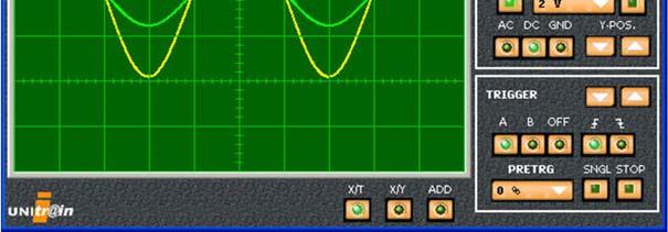
14 Experiments - Inductive displacement Now move the core of the coil to its centre position (i.e. to scale division 20). Set the potentiometer for setting the zero point so that the amplitude of the bridge voltage reaches its minimum value. Copy the resulting oscilloscope trace into the placeholder below. Assoc. Prof. Ossama Abouelatta, Mechanical Engineering Department, Faculty of Engineering, Albaha University (27) Experiments - Inductive displacement What are the amplitude and frequency of the bridge voltage after the calibration has been successfully completed? Enter your answer into the text box below. Assoc. Prof. Ossama Abouelatta, Mechanical Engineering Department, Faculty of Engineering, Albaha University (28)

.")
")

15 Experiments - Inductive displacement Parameters for the differential amplifier The following experiment investigates how the differential amplifier functions. Expand the set-up for the previous experiment so that channel B of the oscilloscope shows the output from the differential amplifier (see following graphic). Change the settings for the oscilloscope as follows: Assoc. Prof. Ossama Abouelatta, Mechanical Engineering Department, Faculty of Engineering, Albaha University (29) Experiments - Inductive displacement Now move the core of the coil to its lower limit (i.e. to scale division 0) and perform the experiment again. Copy the resulting oscilloscope trace into the placeholder below. Assoc. Prof. Ossama Abouelatta, Mechanical Engineering Department, Faculty of Engineering, Albaha University (30)


16 Experiments - Inductive displacement Now move the core to its upper limit (i.e. to scale division 40) and repeat the experiment again. Copy the resulting oscilloscope trace into the placeholder below. Assoc. Prof. Ossama Abouelatta, Mechanical Engineering Department, Faculty of Engineering, Albaha University (31) Experiments - Inductive displacement What is the phase difference between the bridge voltage and the output of the differential amplifier? What is the gain of the differential amplifier? Enter your answers into the text box below. Assoc. Prof. Ossama Abouelatta, Mechanical Engineering Department, Faculty of Engineering, Albaha University (32)
17 Thank You Ossama Abouelatta Mechanical Engineering Department Faculty of Engineering Albaha University Albaha, KSA Assoc. Prof. Ossama Abouelatta, Mechanical Engineering Department, Faculty of Engineering, Albaha University (33)
Advanced Measurements
 Albaha University Faculty of Engineering Mechanical Engineering Department Lecture 3: Position, Displacement, and Level Ossama Abouelatta o_abouelatta@yahoo.com Mechanical Engineering Department Faculty
Advanced Measurements
 Albaha University Faculty of Engineering Mechanical Engineering Department Lecture 9: Wheatstone Bridge and Filters Ossama Abouelatta o_abouelatta@yahoo.com Mechanical Engineering Department Faculty of
Position Sensors. The Potentiometer.
 Position Sensors In this tutorial we will look at a variety of devices which are classed as Input Devices and are therefore called "Sensors" and in particular those sensors which are Positional in nature
09-2 EE 4770 Lecture Transparency. Formatted 12:49, 19 February 1998 from lsli
 09-1 09-1 Displacement and Proximity Displacement transducers measure the location of an object. Proximity transducers determine when an object is near. Criteria Used in Selection of Transducer How much
5. Transducers Definition and General Concept of Transducer Classification of Transducers
 5.1. Definition and General Concept of Definition The transducer is a device which converts one form of energy into another form. Examples: Mechanical transducer and Electrical transducer Electrical A
Sensors. Chapter 3. Storey: Electrical & Electronic Systems Pearson Education Limited 2004 OHT 3.1
 Sensors Chapter 3 Introduction Describing Sensor Performance Temperature Sensors Light Sensors Force Sensors Displacement Sensors Motion Sensors Sound Sensors Sensor Interfacing Storey: Electrical & Electronic
Electronic Systems - B1 23/04/ /04/ SisElnB DDC. Chapter 2
 Politecnico di Torino - ICT school Goup B - goals ELECTRONIC SYSTEMS B INFORMATION PROCESSING B.1 Systems, sensors, and actuators» System block diagram» Analog and digital signals» Examples of sensors»
ELECTRONIC SYSTEMS. Introduction. B1 - Sensors and actuators. Introduction
 Politecnico di Torino - ICT school Goup B - goals ELECTRONIC SYSTEMS B INFORMATION PROCESSING B.1 Systems, sensors, and actuators» System block diagram» Analog and digital signals» Examples of sensors»
Length and Position Measurement
 Length and Position Measurement Primary standards were once based on the length of a bar of metal at a given temperature. The present standard is: 1 meter = distance traveled by light in a vacuum in 3.335641
As before, the speed resolution is given by the change in speed corresponding to a unity change in the count. Hence, for the pulse-counting method
 Velocity Resolution with Step-Up Gearing: As before, the speed resolution is given by the change in speed corresponding to a unity change in the count. Hence, for the pulse-counting method It follows that
Synchronous Machines Study Material
 Synchronous machines: The machines generating alternating emf from the mechanical input are called alternators or synchronous generators. They are also known as AC generators. All modern power stations
PART A. 1. List the types of DC Motors. Give any difference between them. BTL 1 Remembering
 UNIT I DC MACHINES Three phase circuits, a review. Construction of DC machines Theory of operation of DC generators Characteristics of DC generators Operating principle of DC motors Types of DC motors
PVA Sensor Specifications
 Position, Velocity, and Acceleration Sensors 24.1 Sections 8.2-8.5 Position, Velocity, and Acceleration (PVA) Sensors PVA Sensor Specifications Good website to start your search for sensor specifications:
Sensors (Transducer) Introduction By Sintayehu Challa
 Introduction By Sintayehu Challa") Sensors (Transducer) Introduction What are Sensors? Basically the quantities to be measured are Non-Electrical quantities such as temperature, pressure,displacement,humidity, fluid flow, speed etc, but
Sensors (Transducer) Introduction What are Sensors? Basically the quantities to be measured are Non-Electrical quantities such as temperature, pressure,displacement,humidity, fluid flow, speed etc, but
VARIABLE INDUCTANCE TRANSDUCER
 VARIABLE INDUCTANCE TRANSDUCER These are based on a change in the magnetic characteristic of an electrical circuit in response to a measurand which may be displacement, velocity, acceleration, etc. 1.
MEASUREMENT AND INSTRUMENTATION QUESTION BANK UNIT I INTRODUCTION. Part A
 MEASUREMENT AND INSTRUMENTATION QUESTION BANK UNIT I INTRODUCTION Part A 1. Define Standard deviation. 2. Why calibration of instrument is important? 3. What are the different calibration methodologies?
Industrial Sensors. Proximity Mechanical Optical Inductive/Capacitive. Position/Velocity Potentiometer LVDT Encoders Tachogenerator
 Proximity Mechanical Optical Inductive/Capacitive Position/Velocity Potentiometer LVDT Encoders Tachogenerator Force/Pressure Vibration/acceleration Industrial Sensors 1 Definitions Accuracy: The agreement
Introduction. ELCT903, Sensor Technology Electronics and Electrical Engineering Department 1. Dr.-Eng. Hisham El-Sherif
 Introduction In automation industry every mechatronic system has some sensors to measure the status of the process variables. The analogy between the human controlled system and a computer controlled system
Electronic Instrumentation and Measurements
 Electronic Instrumentation and Measurements A fundamental part of many electromechanical systems is a measurement system that composed of four basic parts: Sensors Signal Conditioning Analog-to-Digital-Conversion
Principles of operation 5
 Principles of operation 5 The following section explains the fundamental principles upon which Solartron Metrology s linear measurement products are based. > Inductive technology (gauging and displacement)
Ultrasonic. Advantages
 Ultrasonic Advantages Non-Contact: Nothing touches the target object Measures Distance: The distance to the target is measured, not just its presence Long and Short Range: Objects can be sensed from 2
Question Paper Code : B.E./B.Tech. DEGREE EXAMINATION, NOVEMBER/DECEMBER Third Semester. Electrical and Electronics Engineering
 Question Paper Code : 31391 B.E./B.Tech. DEGREE EXAMINATION, NOVEMBER/DECEMBER 2013. Third Semester Electrical and Electronics Engineering EE 2201/EE 33/EI 1202/10133 EE 302/080280016 MEASUREMENTS AND
 VIDYARTHIPLUS - ANNA UNIVERSITY ONLINE STUDENTS COMMUNITY UNIT 1 DC MACHINES PART A 1. State Faraday s law of Electro magnetic induction and Lenz law. 2. Mention the following functions in DC Machine (i)
IT.MLD900 SENSORS AND TRANSDUCERS TRAINER. Signal Conditioning
 SENSORS AND TRANSDUCERS TRAINER IT.MLD900 The s and Instrumentation Trainer introduces students to input sensors, output actuators, signal conditioning circuits, and display devices through a wide range
Sensors and Sensing Motors, Encoders and Motor Control
 Sensors and Sensing Motors, Encoders and Motor Control Todor Stoyanov Mobile Robotics and Olfaction Lab Center for Applied Autonomous Sensor Systems Örebro University, Sweden todor.stoyanov@oru.se 13.11.2014
Computer Numeric Control
 Computer Numeric Control TA202A 2017-18(2 nd ) Semester Prof. J. Ramkumar Department of Mechanical Engineering IIT Kanpur Computer Numeric Control A system in which actions are controlled by the direct
Mechatronics System Design - Sensors
 Mechatronics System Design - Sensors Aim of this class 1. The functional role of the sensor? 2. Displacement, velocity and visual sensors? 3. An integrated example-smart car with visual and displacement
Syllabus Recording Devices
 Syllabus Recording Devices Introduction, Strip chart recorders, Galvanometer recorders, Null balance recorders, Potentiometer type recorders, Bridge type recorders, LVDT type recorders, Circular chart
Introduction to Measurement Systems
 MFE 3004 Mechatronics I Measurement Systems Dr Conrad Pace Page 4.1 Introduction to Measurement Systems Role of Measurement Systems Detection receive an external stimulus (ex. Displacement) Selection measurement
MECE 3320 Measurements & Instrumentation. Data Acquisition
 MECE 3320 Measurements & Instrumentation Data Acquisition Dr. Isaac Choutapalli Department of Mechanical Engineering University of Texas Pan American Sampling Concepts 1 f s t Sampling Rate f s 2 f m or
How to Select the Right Positioning Sensor Solution A WHITE PAPER
 How to Select the Right Positioning Sensor Solution A WHITE PAPER Published 10/1/2012 Today s machinery and equipment are continuously evolving, designed to enhance efficiency and built to withstand harsher
PRESENTED BY HUMANOID IIT KANPUR
 SENSORS & ACTUATORS Robotics Club (Science and Technology Council, IITK) PRESENTED BY HUMANOID IIT KANPUR October 11th, 2017 WHAT ARE WE GOING TO LEARN!! COMPARISON between Transducers Sensors And Actuators.
1. Position detection on a spindle drive unit by means of a linear potentiometer
 Displacement measurements 1. Position detection on a spindle drive unit by means of a linear potentiometer Learning contents: Mechanical assembly and electrical connection of a spindle drive unit Mechanical
Inductance. Chapter 30. PowerPoint Lectures for University Physics, Thirteenth Edition Hugh D. Young and Roger A. Freedman. Lectures by Wayne Anderson
 Chapter 30 Inductance PowerPoint Lectures for University Physics, Thirteenth Edition Hugh D. Young and Roger A. Freedman Lectures by Wayne Anderson Goals for Chapter 30 To learn how current in one coil
Instrumentation (ch. 4 in Lecture notes)
") TMR7 Experimental methods in Marine Hydrodynamics week 35 Instrumentation (ch. 4 in Lecture notes) Measurement systems short introduction Measurement using strain gauges Calibration Data acquisition Different
TMR7 Experimental methods in Marine Hydrodynamics week 35 Instrumentation (ch. 4 in Lecture notes) Measurement systems short introduction Measurement using strain gauges Calibration Data acquisition Different
UNIT 10 INTRODUCTION TO TRANSDUCERS AND SENSORS
 UNIT 10 INTRODUCTION TO TRANSDUCERS AND SENSORS Structure 10.1 Introduction Objectives 10.2 Active and Passive Sensors 10.3 Basic Requirements of a Sensor/Transducer 10.4 Discrete Event Sensors 10.4.1
FMCET UNIT I - INTRODUCTION
 UNIT I - INTRODUCTION 1. Write the main static characteristics? (April/may 2008) The main static characteristics are: Accuracy Sensitivity Reproducibility Drift Static error Dead zone Resolution Precision
Sensors and Actuators Introduction to sensors
 Sensors and Actuators Introduction to sensors Sander Stuijk (s.stuijk@tue.nl) Department of Electrical Engineering Electronic Systems INDUCTIVE SENSORS (Chapter 3.4, 7.3) 3 Inductive sensors 4 Inductive
Chapter 7: Instrumentation systems
 Chapter 7: Instrumentation systems Learning Objectives: At the end of this topic you will be able to: describe the use of the following analogue sensors: thermistors strain gauge describe the use of the
SERVO MOTOR CONTROL TRAINER
 SERVO MOTOR CONTROL TRAINER UC-1780A FEATURES Open & closed loop speed and position control. Analog and digital control techniques. PC based instrumentation include oscilloscope, multimeter and etc. PC
A. K. Sawhney - A course in Electrical and electronics measurement and Instrumentation, Dhanpatrai & Sons
 Ruchi Gajjar A. K. Sawhney - A course in Electrical and electronics measurement and Instrumentation, Dhanpatrai & Sons It is necessary to have a permanent record or state of a phenomenon being investigated
ACTUATORS AND SENSORS. Joint actuating system. Servomotors. Sensors
 ACTUATORS AND SENSORS Joint actuating system Servomotors Sensors JOINT ACTUATING SYSTEM Transmissions Joint motion low speeds high torques Spur gears change axis of rotation and/or translate application
Module 1. Introduction. Version 2 EE IIT, Kharagpur
 Module 1 Introduction Lesson 1 Introducing the Course on Basic Electrical Contents 1 Introducing the course (Lesson-1) 4 Introduction... 4 Module-1 Introduction... 4 Module-2 D.C. circuits.. 4 Module-3
TAMIL NADU PUBLIC SERVICE COMMISSION. Post of Principal / Assistant Director (Training) Included in the Tamil Nadu Employment and Training Service
 Included in the Tamil Nadu Employment and Training Service") Code No.207 TAMIL NADU PUBLIC SERVICE COMMISSION Post of Principal / Assistant Director (Training) Included in the Tamil Nadu Employment and Training Service Electronics and Instrumentation Engineering
Code No.207 TAMIL NADU PUBLIC SERVICE COMMISSION Post of Principal / Assistant Director (Training) Included in the Tamil Nadu Employment and Training Service Electronics and Instrumentation Engineering
Lab 2A: Introduction to Sensing and Data Acquisition
 Lab 2A: Introduction to Sensing and Data Acquisition Prof. R.G. Longoria Department of Mechanical Engineering The University of Texas at Austin June 12, 2014 1 Lab 2A 2 Sensors 3 DAQ 4 Experimentation
Automatic Control System
 Sensor types Automatic Control System Automatic Control System Construction Material or Power Object Output Signal Sensor Disturbances Converter Measuring Device Controller Industry Controller Executive
Measurement, Sensors, and Data Acquisition in the Two-Can System
 Measurement, Sensors, and Data Acquisition in the Two-Can System Prof. R.G. Longoria Updated Fall 2010 Goal of this week s lab Gain familiarity with using sensors Gain familiarity with using DAQ hardware
System-on-Chip for Rotation Detection
 System-on-Chip for Rotation Detection Author: Christian Hernitscheck Rotation detection has to be done in several applications. Such end-equipments are a bike computer, motor control applications, general
1. A transducer converts
 1. A transducer converts a. temperature to resistance b. force into current c. position into voltage d. one form of energy to another 2. Whose of the following transducers the output is a change in resistance?
Ch 5 Hardware Components for Automation
 Ch 5 Hardware Components for Automation Sections: 1. Sensors 2. Actuators 3. Analog-to-Digital Conversion 4. Digital-to-Analog Conversion 5. Input/Output Devices for Discrete Data Computer-Process Interface
Water Meter Basics Incremental encoders
 Water Meter Basics Measuring flow can be accomplished in a number of ways. For residential applications, the two most common approaches are turbine and positive displacement technologies. The turbine meters
Shaft encoders are digital transducers that are used for measuring angular displacements and angular velocities.
 Shaft Encoders: Shaft encoders are digital transducers that are used for measuring angular displacements and angular velocities. Encoder Types: Shaft encoders can be classified into two categories depending
The AD620 Instrumentation Amplifier and the Strain Gauge Building the Electronic Scale
 BE 209 Group BEW6 Jocelyn Poruthur, Justin Tannir Alice Wu, & Jeffrey Wu October 29, 1999 The AD620 Instrumentation Amplifier and the Strain Gauge Building the Electronic Scale INTRODUCTION: In this experiment,
INDEX IEC:
 60050-300 IEC:2001 173 INDEX A absolute absolute error... 311-01-05 (absolute) frequency deviation... 314-08-07 accessory accessory (of a measuring instrument)... 312-03-01 accessory of limited interchangeability...
 Code No: M0326 /R07 Set No. 1 1. Define Mechatronics and explain the application of Mechatronics in CNC Machine tools and Computer Integrated Manufacturing (CIM). 2. (a) What are the various Filters that
AERO2705 Space Engineering 1 Week 7 The University of Sydney
 AERO2705 Space Engineering 1 Week 7 The University of Sydney Presenter Mr. Warwick Holmes Executive Director Space Engineering School of Aerospace, Mechanical and Mechatronic Engineering The University
Table of Contents...2. About the Tutorial...6. Audience...6. Prerequisites...6. Copyright & Disclaimer EMI INTRODUCTION Voltmeter...
 1 Table of Contents Table of Contents...2 About the Tutorial...6 Audience...6 Prerequisites...6 Copyright & Disclaimer...6 1. EMI INTRODUCTION... 7 Voltmeter...7 Ammeter...8 Ohmmeter...8 Multimeter...9
Actuator Components 2
 Actuator Components 2 Term project midterm review Bearings Seals Sensors 1 Actuator Components Term Project Midterm Review Details of term project are contained in first lecture of the term Should be using
Filters And Waveform Shaping
 Physics 3330 Experiment #3 Fall 2001 Purpose Filters And Waveform Shaping The aim of this experiment is to study the frequency filtering properties of passive (R, C, and L) circuits for sine waves, and
Lecture 5. In The Name of Allah. Instrumentation. Dr. Ali Karimpour Associate Professor Ferdowsi University of Mashhad
 In The Name of Allah Instrumentation Dr. Ali Karimpour Associate Professor Ferdowsi University of Mashhad Position Sensors Topics to be covered include: v v v v v v Introduction Resistive Displacement
Sensors and Sensing Motors, Encoders and Motor Control
 Sensors and Sensing Motors, Encoders and Motor Control Todor Stoyanov Mobile Robotics and Olfaction Lab Center for Applied Autonomous Sensor Systems Örebro University, Sweden todor.stoyanov@oru.se 05.11.2015
CS545 Contents XIV. Components of a Robotic System. Signal Processing. Reading Assignment for Next Class
 CS545 Contents XIV Components of a Robotic System Power Supplies and Power Amplifiers Actuators Transmission Sensors Signal Processing Linear filtering Simple filtering Optimal filtering Reading Assignment
9/28/2010. Chapter , The McGraw-Hill Companies, Inc.
 Chapter 4 Sensors are are used to detect, and often to measure, the magnitude of something. They basically operate by converting mechanical, magnetic, thermal, optical, and chemical variations into electric
Sensors for Mechatronics
 Sensors for Mechatronics Paul P.L Regtien Hertgelo The Netherlands AMSTERDAM BOSTON HEIDELBERG LONDON NEW YORK' OXFORD ELSEVIER PARIS SAN DIEGO SAN FRANCISCO SINGAPORE SYDNEY TOKYO Contents Preface xi
Curriculum. Technology Education ELECTRONICS
 Curriculum Technology Education ELECTRONICS Supports Academic Learning Expectation # 3 Students and graduates of Ledyard High School will employ problem-solving skills effectively Approved by Instructional
USE OF INDUCTIVE PROXIMITY SENSORS IN VITAL SIGNAL APPLICATIONS
 Union Switch & Signal Inc., an Ansaldo Signal company www.switch.com 1000 Technology Drive, Pittsburgh, PA 15219? 645 Russell Street, Batesburg, SC 29006 412-688-2400 USE OF INDUCTIVE PROXIMITY SENSORS
MEP 382: Design of Applied Measurement Systems Lecture 5: Signal Conditioning
 Faculty of Engineering MEP 382: Design of Applied Measurement Systems Lecture 5: Signal Conditioning Transducer Last Week - Sensors Bridge Completion Excitation Amplification Signal Conditioner Low Pass
Robot Sensors Introduction to Robotics Lecture Handout September 20, H. Harry Asada Massachusetts Institute of Technology
 Robot Sensors 2.12 Introduction to Robotics Lecture Handout September 20, 2004 H. Harry Asada Massachusetts Institute of Technology Touch Sensor CCD Camera Vision System Ultrasonic Sensor Photo removed
INSTITUTE OF AERONAUTICAL ENGINEERING (AUTONOMOUS) Dundigal, Hyderabad
 Dundigal, Hyderabad") INSTITUTE OF AERONAUTICAL ENGINEERING (AUTONOMOUS) Dundigal, Hyderabad - 500 043 CIVIL ENGINEERING ASSIGNMENT Name : Electrical and Electronics Engineering Code : A30203 Class : II B. Tech I Semester Branch
INSTITUTE OF AERONAUTICAL ENGINEERING (AUTONOMOUS) Dundigal, Hyderabad - 500 043 CIVIL ENGINEERING ASSIGNMENT Name : Electrical and Electronics Engineering Code : A30203 Class : II B. Tech I Semester Branch
Introduction to Internet of Things Prof. Sudip Misra Department of Computer Science & Engineering Indian Institute of Technology, Kharagpur
 Introduction to Internet of Things Prof. Sudip Misra Department of Computer Science & Engineering Indian Institute of Technology, Kharagpur Lecture - 03 Sensing So, we have already understood the basics
Where: (J LM ) is the load inertia referred to the motor shaft. 8.0 CONSIDERATIONS FOR THE CONTROL OF DC MICROMOTORS. 8.
 is the load inertia referred to the motor shaft. 8.0 CONSIDERATIONS FOR THE CONTROL OF DC MICROMOTORS. 8.") Where: (J LM ) is the load inertia referred to the motor shaft. 8.0 CONSIDERATIONS FOR THE CONTROL OF DC MICROMOTORS 8.1 General Comments Due to its inherent qualities the Escap micromotor is very suitable
Where: (J LM ) is the load inertia referred to the motor shaft. 8.0 CONSIDERATIONS FOR THE CONTROL OF DC MICROMOTORS 8.1 General Comments Due to its inherent qualities the Escap micromotor is very suitable
Electromagnetic Oscillations and Currents. March 23, 2014 Chapter 30 1
 Electromagnetic Oscillations and Currents March 23, 2014 Chapter 30 1 Driven LC Circuit! The voltage V can be thought of as the projection of the vertical axis of the phasor V m representing the time-varying
MAGNETIC LEVITATION SUSPENSION CONTROL SYSTEM FOR REACTION WHEEL
 IMPACT: International Journal of Research in Engineering & Technology (IMPACT: IJRET) ISSN 2321-8843 Vol. 1, Issue 4, Sep 2013, 1-6 Impact Journals MAGNETIC LEVITATION SUSPENSION CONTROL SYSTEM FOR REACTION
Inductive Sensors. Fig. 1: Geophone
 Inductive Sensors A voltage is induced in the loop whenever it moves laterally. In this case, we assume it is confined to motion left and right in the figure, and that the flux at any moment is given by
Course of Instrumentation. and Measurement. National School of Engineers of Tunis ENIT. Karim Bourouni. Dipl.Dr-Ing.
 1 Course of Instrumentation and Measurement Karim Bourouni National School of Engineers of Tunis ENIT Dipl.Dr-Ing. (R.U. Energetic of Buildings and Solar Systems) Industrial Engineering Department 2 Plan
Fatigue testing. Fatigue design
 Fatigue testing Lecture at SP Technical Research Institute of Sweden April 14, 2008 Gunnar Kjell SP Building Technology and Mechanics E-mail: gunnar.kjell@sp.se Fatigue design Need for material data (Distribution
Inductance. Chapter 30. PowerPoint Lectures for University Physics, Thirteenth Edition Hugh D. Young and Roger A. Freedman. Lectures by Wayne Anderson
 Chapter 30 Inductance PowerPoint Lectures for University Physics, Thirteenth Edition Hugh D. Young and Roger A. Freedman Lectures by Wayne Anderson Goals for Chapter 30 To learn how current in one coil
White Paper. Balluff SmartLevel Technology Accurate, Reliable Level Detection
 White Paper Balluff SmartLevel Technology Accurate, Reliable Level Detection 1 Level detection applications of dipolar or heavily foaming liquids are a difficult task for standard capacitive sensors today:
The University of New South Wales. School of Electrical Engineering and Telecommunications. High Voltage Systems ELEC9712. Appendix Partial Discharge
 The University of New South Wales School of Electrical Engineering and Telecommunications High Voltage Systems ELEC9712 Appendix Partial Discharge Content Introduction Quantities measured Test circuits
Lecture 36 Measurements of High Voltages (cont) (Refer Slide Time: 00:14)
 (Refer Slide Time: 00:14)") Advances in UHV Transmission and Distribution Prof. B Subba Reddy Department of High Voltage Engg (Electrical Engineering) Indian Institute of Science, Bangalore Lecture 36 Measurements of High Voltages
Advances in UHV Transmission and Distribution Prof. B Subba Reddy Department of High Voltage Engg (Electrical Engineering) Indian Institute of Science, Bangalore Lecture 36 Measurements of High Voltages
System Inputs, Physical Modeling, and Time & Frequency Domains
 System Inputs, Physical Modeling, and Time & Frequency Domains There are three topics that require more discussion at this point of our study. They are: Classification of System Inputs, Physical Modeling,
Gurley Model HR2A High-resolution Interpolator. High resolution - Industrial ruggedness
 Gurley Model High-resolution Interpolator Application: Selected linear and rotary incremental encoders Output: Compatible with virtually all counter circuits, dedicated encoder interface cards and PLCs
DSC Lab 2: Force and Displacement Measurement Page 1
 DSC Lab 2: Force and Displacement Measurement Page 1 Overview of Laboratory on Force and Displacement Measurement This lab course introduces concepts in force and motion measurement using strain-gauge
A High Precision Electronic Scale Based on STM32. Jiahui Chen
 2nd International Conference on Automation, Mechanical Control and Computational Engineering (AMCCE 2017) A High Precision Electronic Scale Based on STM32 Jiahui Chen Department of Electronic and Communication
FLAW DETECTION USING ENCIRCLING COIL EDDY CURRENT SYSTEMS
 DATA SHEET NO GI-2 Magnetic Analysis Corporation FLAW DETECTION USING ENCIRCLING COIL EDDY CURRENT SYSTEMS PRINCIPLES OF OPERATION The detection of flaws such as seams, cracks, pits, slivers, weld-line
1. Explain in detail the constructional details and working of DC motor.
 DHANALAKSHMI SRINIVASAN INSTITUTE OF RESEARCH AND TECHNOLOGY, PERAMBALUR DEPT OF ECE EC6352-ELECTRICAL ENGINEERING AND INSTRUMENTATION UNIT 1 PART B 1. Explain in detail the constructional details and
EE T55 MEASUREMENTS AND INSTRUMENTATION
 EE T55 MEASUREMENTS AND INSTRUMENTATION UNIT V: TRANSDUCERS Temperature transducers-rtd, thermistor, Thermocouple-Displacement transducer-inductive, capacitive, LVDT, Pressure transducer Bourdon tube,
Power and Energy Measurements. MYcsvtu Notes
 Power and Energy Measurements Contest Power measurements DC circuits AC circuits Three-phase systems High-frequency power measurements Energy measurements DC circuits AC circuits Example: Power and energy
Application Note # 5438
 Application Note # 5438 Electrical Noise in Motion Control Circuits 1. Origins of Electrical Noise Electrical noise appears in an electrical circuit through one of four routes: a. Impedance (Ground Loop)
Load Cells, LVDTs and Thermocouples
 Load Cells, LVDTs and Thermocouples Introduction Load cells are utilized in nearly every electronic weighing system while LVDTs are used to measure the displacement of a moving object. Thermocouples have
Motor Repair Electrical Engineering Maintenance
 46 Motor Repair Electrical Engineering Maintenance The -Class Facilitate complicated things Tester for checking shaft encoders... 48 www.schleich.com 47 The -Class Tester for checking shaft encoders Ethernet
2.5D Finite Element Simulation Eddy Current Heat Exchanger Tube Inspection using FEMM
 Vol.20 No.7 (July 2015) - The e-journal of Nondestructive Testing - ISSN 1435-4934 www.ndt.net/?id=18011 2.5D Finite Element Simulation Eddy Current Heat Exchanger Tube Inspection using FEMM Ashley L.
M.D. Singh J.G. Joshi MECHATRONICS
 M.D. Singh J.G. Joshi MECHATRONICS MECHATRONICS MECHATRONICS M.D. SINGH Formerly Principal Sagar Institute of Technology and Research Bhopal J.G. JOSHI Lecturer Department of Electronics and Telecommunication
Incremental encoders, absolute encoders & pseudo-absolute encoders
 T E C H N I C A L W H I T E P A P E R Incremental encoders, absolute encoders & pseudo-absolute encoders Author: Mark Howard, General Manager, Zettlex UK Ltd File ref: technical articles/incremental encoders
An Instrumentation System
 Transducer As Input Elements to Instrumentation System An Instrumentation System Input signal (measurand) electrical or non-electrical Input Device Signal Conditioning Circuit Output Device? -amplifier
CAPACITIVE FOR WINDING ELECTRIC MOTORS, TRANSFORMERS AND ELECTRO-MAGNETS
 CAPACITIVE FOR WINDING ELECTRIC MOTORS, TRANSFORMERS AND ELECTRO-MAGNETS The invention relates to a capacitive coil of copper wire that can be used for all electromagnetic energy converters and their inductive
MEASUREMENT AND STANDARDS
 MEASUREMENT AND STANDARDS I. MEASUREMENT PRINCIPLES 1. MEASUREMENT SYSTEMS Measurement is a process of associating a number with a quantity by comparing the quantity to a standard Instrument refers to
XTS: Significantly higher performance and simplified engineering with TwinCAT. products PC Control
 products PC Control 04 2012 Position calculation Velocity calculation Position control Velocity control Phase transformation Position sensor signals Complete lt control cycle for all movers in 250 μs Set
An induced emf is the negative of a changing magnetic field. Similarly, a self-induced emf would be found by
 This is a study guide for Exam 4. You are expected to understand and be able to answer mathematical questions on the following topics. Chapter 32 Self-Induction and Induction While a battery creates an
Basic NC and CNC. Dr. J. Ramkumar Professor, Department of Mechanical Engineering Micro machining Lab, I.I.T. Kanpur
 Basic NC and CNC Dr. J. Ramkumar Professor, Department of Mechanical Engineering Micro machining Lab, I.I.T. Kanpur Micro machining Lab, I.I.T. Kanpur Outline 1. Introduction to CNC machine 2. Component