INTRODUCTION TOOLS AND SUPPLIES
|
|
|
- Jeremy Wiggins
- 6 years ago
- Views:
Transcription
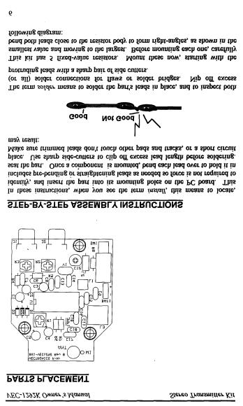
1 INTRODUCTION General Information: This nifty little transmitter will send your favorite tunes with you--throughout the house or out in the yard. Wish your Walkman TM had a CD player? No problem! Connect the VEC-1292K to your stereo's CD player and broadcast it to where you are. Can't pick up that distant FM station down in your basement shop? Simple! Connect the VEC-1292K to your stereo's FM tuner (the one with the big antenna), and rebroadcast the program on a clear channel. Thanks to the transmitter's specialized IC, you get true stereo with outstanding signal quality--just like FM radio stations generate from their studios. The uses are endless! Circuitry: The VEC-1292K uses a sophisticated IC containing all of the circuitry needed for a miniature FM broadcast station. The audio stages, multiplex-stereo modulator, and transmitter RF section are all there--on one chip! The transmitter's sub-carrier oscillator is crystal controlled for rock-steady stereo lock-up on receivers. A channel balance control ensures perfect symmetry. It's even pre-emphasized for the 75 us US-broadcast standard. The IC has everything you need to put a broadcast-quality stereo signal on the air in your own home. Operating frequency is internally adjustable, and a tuned output network matches the transmitter to a built-in collapsible antenna. TOOLS AND SUPPLIES Construction Area: Kit construction requires a clean, smooth, and well-lighted area where you can easily organize and handle small parts without losing them. An inexpensive sheet of white poster board makes an excellent construction surface, while providing protection for the underlying table or desk. Diffused overhead lighting is a plus, and a supplemental high-intensity desk lamp is especially helpful for close-up work. Safety is always important! Use a suitable high-temperature stand for your soldering iron, and keep the work area free of clutter. Universal Kit-building Tools: No special tools are required to complete this kit beyond common items normally used for bench construction. We recommend the following:! Soldering iron (grounded-tip and temperature-controlled preferred)! High-temperature iron holder with cleaning sponge! Solder, 60/40 or 37/63 with rosin or "no-clean" flux (.031" dia. is good size).! Needle nose pliers or surgical hemostats 1
2 ! Diagonal cutters or "nippy cutters"! Solder sucker (squeeze or vacuum pump type), or desoldering braid! Bright desk lamp! Magnifying glass! Insulated tuning tool set BEFORE YOU START BUILDING Experience shows there are four common mistakes builders make. Avoid these, and your kit will probably work on the first try! Here's what they are: 1. Installing the Wrong Part: It always pays to double-check each step. A 1K and a 10K resistor may look almost the same, but they may act very differently in an electronic circuit! Same for capacitors--a device marked 102 (or.001 uf) may have very different operating characteristics from one marked 103 (or.01uf). 2. Installing Parts Backwards: Always check the polarity of electrolytic capacitors to make sure the positive (+) lead goes in the (+) hole on the circuit board. ICs have a notch or dot at one end indicating the correct direction of insertion. Always double-check--especially before applying power to the circuit! 3. Faulty Solder Connections: Inspect for cold-solder joints and solder bridges. Cold solder joints happen when you don't fully heat the connection-- or when metallic corrosion and oxide contaminate a component lead or pad. Solder bridges form when a trail of excess solder shorts pads or tracks together (see solder tips below). 4. Omitting or Misreading a Part: This is easier to do than you might think! Always double-check to make sure you completed each step in an assembly sequence. Soldering Tips: Cleanliness and good heat distribution are the two secrets of professional soldering. Before you install and solder each part, inspect leads or pins for oxidation. If the metal surface is dull, sand with fine emery paper until shiny. Allow the tip of your iron to contact both the lead and pad for about one second (count "one-thousand-one") before feeding solder to the connection. Surfaces must become hot enough for solder to flow smoothly. Feed solder to the opposite side of the lead from your iron tip--solder will wick around the lead toward the tip, wetting all exposed surfaces. Apply solder sparingly, and do not touch solder directly to the hot iron tip to promote rapid melting. Keep a damp sponge handy to wipe your soldering tip on. This removes excess solder, and 2
3 keeps the tip properly tinned. If the iron is going to sit idling for long periods, wipe the tip, add some fresh solder, and unplug the iron. Desoldering Tips: If you make a mistake and need to remove a part, follow these instructions carefully! First, grasp the component with hemostats, needlenose pliers, or your fingers. Heat the pad beneath the lead you intend to extract, and pull gently. The lead should come out. Repeat for the other lead. Solder may fill in behind the lead as you extract it--especially if you are working on a double-sided board with plate-through holes. Should this happen, try heating the pad again and inserting a common pin into the hole. Solder won't stick to the pin's chromium plating. When the pad cools, remove the pin and insert the correct component. For ICs or multiple-pin parts, use desoldering braid to remove excess solder before attempting to extract the part. Alternatively, a lowcost vacuum-bulb or spring-loaded solder sucker may be used. Parts damaged or severely overheated during extraction should be replaced rather than reinstalled. Work Habits: Kit construction requires the ability to follow detailed instructions and, in many cases, to perform new and unfamiliar tasks. To avoid making needless mistakes, work for short periods when you're fresh and alert. Recreational construction project are more informative and more fun when you take your time. Enjoy! Sorting and Reading Resistors: The electrical value of resistors is indicated by a color code (shown below). You don't have to memorize this code to work with resistors, but you do need to understand how it works: 1st Digit 2nd Digit Multiplier Tolerence (gold or silver) Resistor Color Code Black = 0 (tens) Brown = 1 (hundreds) Red = 2 (K) Orange = 3 (10K) Yellow = 4 (100K) Green = 5 (1Meg) Blue = 6 Violet = 7 Gray = 8 White = 9 Silver = 10% Gold = 5% When you look at a resistor, check its multiplier code first. Any resistor with a black multiplier band falls between 10 and 99 ohms in value. Brown designates a value between 100 and 999 ohms. Red indicates a value from 1000 to 9999 ohms, which is also expressed as 1.0K to 9.9K. An orange multiplier band designates 10K to 99K, etc. To inventory resistors, first separate them into groups by multiplier band (make a pile of 10s, 100s, 1Ks, 10Ks, etc.). Next, sort each group by specific value (1K, 2.2K, 4.7K, etc). This procedure makes the inventory easier, and also makes locating specific parts more convenient later on during construction. Some builders find it especially helpful to arrange resistors in ascending order along a strip of double-sided tape. 3
4 Reading Capacitors: Unlike resistors, capacitors no longer use a color code for value identification. Instead, the value, or a 3-number code, is printed on the body. Value Code 10 pf = 100 Multilayer 100 pf = 101 (270 pf) 1000 pf = uf = 102* uf = uf = 104 Ceramic Discs (.001 uf) (.1 uf) Electrolytic 1 uf 1uF 35V - + As with resistors, it's helpful to sort capacitors by type, and then to arrange them in ascending order of value. Small-value capacitors are characterized in pf (or pico-farads), while larger values are labeled in uf (or micro-farads). The transition from pf to uf occurs at 1000 pf (or.001 uf)*. Today, most monolithic and disc-ceramic capacitors are marked with a three-number code. The first two digits indicate a numerical value, while the last digit indicates a multiplier (same as resistors). Electrolytic capacitors are always marked in uf. Electrolytics are polarized devices and must be oriented correctly during installation. If you become confused by markings on the case, remember the uncut negative lead is slightly shorter than the positive lead. Integrated Circuits: Proper IC positioning is indicated by a dot or square marking located on one end of the device. A corresponding mark will be silkscreened on the PC board and printed on the kit's parts-placement diagram. To identify specific IC pin numbers for testing purposes, see the diagram below. Pin numbers always begin at "1" at the keyed end of the case and progress along the device, as shown: Installation Key PARTS LIST Pin Numbers Installation Key Your kit should contain all of the parts listed below. Please identify and inventory each item on the checklist before you start building. If any parts are missing or damaged, refer to the manual's warranty section for replacement 4
5 instructions. If you can't positively identify an unfamiliar item on the basis of the information given, set it aside until all other items are checked off. You may then be able to identify it by process of elimination. Finally, your kit will go together more smoothly if parts are organized by type and arranged by value ahead of time. Use this inventory as an opportunity to sort and arrange parts so you can identify and find them quickly. " Qty Part Description Designation VEC P/N! ohm resistor (yellow-violet-brown) R ! 1 4.7K ohm resistor (yellow-violet-red) R ! 2 75K ohm resistor (violet-green-orange) R4,R ! 1 150K ohm resistor (brown-greenyellow) R ! 2 1K trimpot (102) R2,R ! 1 100K trimpot (104) R ! 2 10 pf multilayer capacitor (10 or 100) C13,C ! 2 15 pf multilayer capacitor (15 or 150) C15,C ! 1 22 pf multilayer capacitor (22 or 220) C18* ! 1 27 pf multilayer capacitor (27 or 270) C18* ! 1 33 pf multilayer capacitor (33 or 330) C18* ! pf multilayer capacitor (221) C ! uf multilayer capacitor (102) C6-C ! 2 10 uf electrolytic capacitor C3,C ! 2 22 uf electrolytic capacitor C1,C ! uf electrolytic capacitor C ! 1 50 pf trimmer capacitor C ! uh variable inductor L S! 1 1 uh molded choke L ! 1 6 piece of magnet wire for L ! 3 1N4148 diode D1-D ! 1 BA1404 FM transmitter IC U ! 1 38 khz crystal (small cylinder, 2 leads) Y ! 1 Miniature power switch, DPDT SW ! 2 RCA jack J1,J ! 1 18 pin socket for U ! 1 9V battery snap ! 1 2 piece of insulated wire xx-0300! 1 Telescoping antenna ! 1 12mm metric screw ! 1 Metric nut ! 1 VEC-1292 printed circuit board 862-VEC1292 *One of these three values will be selected for use at C18--depending on desired frequency range. PARTS PLACEMENT 5
6
7 !! 1. Find a 470 ohm resistor (yellow-violet-brown). Install at R8 and solder.!! 2. Find a 4.7K ohm resistor (yellow-violet-red). Install at R6 and solder. Locate the two 75K ohm resistors (violet-green-orange).!! 3. Install a 75K at R4 and solder.!! 4. Install a 75K at R5 and solder.!! 5. Find the 150K ohm resistor (brown-green-yellow). Install at R7. Next, install the kit's 12 multilayer capacitors. Avoid using force or excessive heat when installing these. If the spacing isn't right, pre-form leads to the correct spacing before inserting into the PC board. Incorrect Ooops! Correct Locate two (2) 10 pf multilayer capacitors (marked 10 or 100).!! 6. Install a 10 pf at C13.!! 7. Install a 10 pf at C14. Locate two (2) 15 pf multilayer capacitors (15 or 150).!! 8. Install a 15 pf at C15.!! 9. Install a 15 pf at C16. The next capacitor determines the frequency-tuning range of your FM transmitter. For the low end of the band, or MHz, find the 33 pf capacitor (33 or 330). For the middle portion of the band, or MHz, find the 27 pf capacitor (27 or 270). For 102 MHz and up, use the 22 pf capacitor (22 or 220).!! 10. Install the capacitor you've selected at C18 and solder.!! 11. Find a 220 pf multilayer capacitor (221). Install at C17 and solder. Locate six (6).001 uf multilayer capacitors (102).!! 12. Install a.001 uf at C6 and solder.!! 13. Install a.001 uf at C7 and solder.!! 14. Install a.001 uf at C8 and solder. 7
8 !! 15. Install a.001 uf at C9 and solder.!! 16. Install a.001 uf at C10 and solder.!! 17. Install a.001 uf at C11 and solder. The last 5 fixed-value capacitors in your kit are electrolytic. Electrolytic caps are polarized and must be installed the correct way in order to work. Each capacitor's plus (+) mounting hole is marked on both the circuit board and parts placement diagram. If the markings on the capacitor body are unclear, the plus (+) lead is always the longer of the two. + Plus Lead Locate the two (2) 10 uf electrolytic capacitors.!! 18. Install a 10 uf at C3 and solder.!! 19. Install a 10 uf at C4 and solder. Locate the two (2) 22 uf electrolytic capacitors.!! 20. Install a 22 uf at C1 and solder.!! 21. Install a 22 uf at C2 and solder.!! 22. Find the 100 uf electrolytic capacitor. Install at C5 and solder. This completes fixed capacitor installation. Before moving on, check each electrolytic for correct polarity. Locate the three (3) 1N4148 diodes (glass body). Like electrolytics, diodes are polarized devices that must be installed correctly. Always look for the banded end when installing.!! 23. Install a 1N4148 at D1 and solder.!! 24. Install a 1N4148 at D2 and solder. 8
9 !! 25. Install a 1N4148 at D3 and solder. There are three small trimpots in your kit. Find the two (2) 1K trimpots (marked 102). When installing these, make sure they remain seated firmly against the board during soldering.!! 26. Install a 1K pot (102) R2 and solder.!! 27. Install a 1K pot (102) R3 and solder.!! 28. Find the remaining 100K trimpot (marked 104). Install at R1 and solder.!! 29. Find the 50 pf trimcap (orange, screwdriver adjust). Install at C12 with the flat side toward L1 and solder. Trimcap Install with the "round to ground" Locate the 38 khz crystal. This is a small metal tube-shaped package with two leads protruding from one end. 38 khz digital watch crystal!! 30. Install the 38 khz crystal at Y1. Locate the.089 uh slug-tuned coil (red plastic coil form, metal shield can). Before installing, make sure the coil's two pins and shield-can tabs are straight.!! 31. Position the.089 uh coil over the silkscreen legend for L3 and insert carefully. Bend the two shield-can tabs over and solder in place. Solder the two wire pins in place.!! 32. Find the 1 uh molded choke (brown-black-gold-silver). Install at L2 and solder. The transmitter's output coil, L1, is a small 5-turn air-wound inductor. Use a screw shaft to make this coil. Ensure there are five complete turns on the coil. After forming the coil, position as shown in the following: 9
10 L1 Note: Separate the turns evenly so the coil fits between the two mounting holes. Y1 L2 R8 SW1 C12 Antenna Lead!! 33. Install the 5-turn coil at L1 and solder. L1 requires the addition of a center tap. If your coil has enamel insulation, locate the center turn and scrape a patch of insulation off with a hobby knife to expose the copper beneath. If the coil has tin plating, disregard this instruction and solder directly to the plating.!! 34. Get the 2" length of insulated wire and strip 1/4" of insulation from both ends (if necessary).!! 35. Tack-solder one end of the insulated wire to the middle turn of L1.!! 36. Place the other end of the insulated into W1 and solder. Your kit contains a miniature DPDT switch. Some versions require installation of a plastic clip-on support at the front of the switch body. This piece relieves stress on the pins and ensures level seating. If your parts kit contains this piece, install as shown: Once the switch is prepared for installation:!! 37. Install the DPDT mini power switch at SW1 The Stereo Transmitter ICs in your kit will be installed using a IC socket. Like the IC itself, the socket is keyed at one end to indicate proper positioning. 10
11 During installation, orient the socket so the notch corresponds to the key on the PC layout. Key Key When installing sockets, make sure all pins enter the mounting holes and appear on the opposite side of the PC board (it's easy to fold one or more under the socket). Also, when soldering, make sure the socket remains flat against the board surface.!! 38. Find a 18 pin IC socket. Orient to U1, install, and solder all pins. Next, align the BA-1404 IC with the socket, matching its key with the socket key. When you install, press in slowly--making sure all pins go into the socket holes and none fold over under the device. Locate the 9-V battery snap clip, and note the red+ lead and black- lead.!! 39. Install the red lead at (+) on the PC board and solder.!! 40. Install the black lead at (-) on the PC board and solder. Locate the two (2) RCA jacks. When installing, make sure all tabs are firmly seated in place and the jack is level prior to soldering.!! 41. Install a RCA jack at J1.!! 42. Install a RCA jack at J2.!! 43. Locate the 12mm meter screw and nut. Place the screw through the ant hole (from the solder side of the PCB) and tighten with the nut.!! 44. Install the antenna by threading it onto the screw. This concludes wiring of your VEC-1292 FM. Before moving on to the next section, perform a thorough QC (quality control) inspection. This will uncover any assembly errors that might prevent it from working properly--or that could damage sensitive parts when you apply power. Follow this procedure: 1. Compare parts locations with the parts-placement diagram. Was each part installed where it is supposed to be? Was the correct value used? Start at one side of the board and work your way across in an organized pattern. 2. Inspect the solder side of the board for cold-solder joints and solder bridges between tracks or pads. Use a magnifying glass to obtain a clear view of the 11
12 track area. If you suspect a solder bridge, hold the board in front of a bright light for a better view. All joints should be smooth and shiny, indicating good solder wetting and flow. Resolder any beaded or dull-appearing connections. Also, check the front-panel jacks, switches, and connectors for defective solder connections. 3. Finally, check electrolytic capacitors and diodes for correct polarity. Does the plus (+) polarity symbol on the part agree with the pictorial and with the pattern on the PC board? Is the banded end of each diode positioned correctly? Were all ICs installed correctly? Be sure to correct all errors before moving on. 12
13 TESTING AND ALIGNMENT To set up your FM transmitter, you'll need a line-level stereo-audio source such as a tape cassette or CD player. You'll also need a FM stereo receiver-- preferably one with digital frequency readout--to monitor the transmitter's signal. Your kit has five internal controls that optimize its operation. No sophisticated test equipment is required to make these adjustments. The set-up for alignment is shown in the following diagram: Audio Source Stereo Balance Frequency Adjust FM-Stero Receiver Input Gain Transmit Peak Power On/Off 20" Antenna To begin alignment: #$Set all three transmitter potentiometers at mid-range (R1, R2, R3). #$Confirm the power switch is Off (button out). #$Install a fresh 9V alkaline battery on the battery clip. #$Turn the power switch on. #$Turn on the FM receiver and tune to locate the transmitter's un-modulated signal. If you are unable to find the signal, your kit may be transmitting "out-of-band". Using an insulated tuning tool, adjust L3 until the signal is picked up (listen near the low-frequency end of the FM band if C18 is 33 pf, and near the high end if it's 22 pf). If you still can't locate the signal, review assembly instructions and look for an assembly error. If you do locate it, proceed as follows: #$Activate your audio source and listen for modulation on the FM receiver. #$Adjust Gain controls R2, R3 for volume levels slightly below average off-air signals. Be sure to make your trimpot settings equal for both channels (we'll adjust the transmitter for channel balance next). Note that commercial FM stations use 13
14 sophisticated audio limiters to boost their average modulation level. Your transmitter doesn't have this feature, so it's best to set the gain trimpots for modulation that's slightly below commercial broadcast levels to prevent overmodulation. Once a modulation level is set, adjust for channel balance. You may find it helpful to wear stereo headphones for this particular adjustment: #$Listen to the signal on your FM receiver. Is the signal undistorted and clear? #$Look at your FM-receiver's stereo pilot--is it "locked up" to a stereo signal? #$Switch between mono and stereo--is there audible channel separation? #$Set the FM receiver's balance control to its center position. #$Adjust the transmitter's balance (R1) for equal volume from both channels. If you don't have a good FM stereo monitor receiver or a well-balanced audio source available, you may simply set the transmitter balance trimpot to its midpoint. In most cases, this will yield satisfactory results. If you have a specific transmitter operating frequency in mind, a FM receiver with digital frequency readout will help you set the transmitter's oscillator accurately (simply tune to that channel). If you merely wish to find a clear channel, tune around for a good one that falls within the tuning range of the transmitter's oscillator. Note that the FCC assigns FM channels for 200 khz spacing, starting 100 khz above the band edge. Channel numbers progress from 88.1, 88.3, etc up to MHz. You may find it beneficial to comply with this standard, since some low-cost synthesized FM receivers tune in 200 khz steps. Begin the frequency-setting procedure by tuning your FM receiver to the desired channel. #$Using an insulated tuning tool, adjust L3 until your transmitter is on frequency. If you have a discriminator indicator (or tuning meter) on your stereo receiver, use this when fine-tuning L3. If this feature isn't available, set L3 for leastdistorted audio--making sure the receiver's stereo pilot illuminates. This indicates the FM receiver is locked onto the transmitter's stereo sub-carrier. Note that some frequency drift is normal for simple L/C tuned oscillator circuits, so you should expect some variation in transmit frequency over time. To adjust the transmitter's output peaking control, use your FM receiver's signalstrength meter. If the meter deflects full scale during this operation, remove the receiver's antenna to reduce sensitivity. #$Using an insulated tuning tool, set C12 for maximum meter deflection. 14
15 This completes alignment of your transmitter. Note that readjustment of the transmitter's gain controls R2, R3 may be necessary if you substitute an audio source with significantly higher or lower output level. Always re-check your modulation level against a commercial station when connecting to a new audio source. Important Warning: As the builder and operator of this transmitter circuit, you are solely responsible for its legal use. Please note that connecting a transmitter of this type to a full-sized outdoor FM band antenna for the purpose of "neighborhood broadcasting" constitutes a clear violation of FCC Rules under Part 95. It is also a violation of FCC rules to cause willful or harmful interference to the normal reception of commercial FM broadcast signals. Verctronics cannot be held responsible for the misuse or illicit modification of this product. If you have purchased the matching case for your VEC-1292K, now is a good time to install it. 15
16 OPERATING INSTRUCTIONS Once your VEC-1292K is set up, its operation is relatively simple. A typical setup is illustrated below: Antenna Audio Connections VEC-1292 Power CD Player Power: Press the unit's power switch "in" to activate the transmitter. Press to the "out" position to turn the transmitter off. Always check the switch before storing to ensure that the unit wasn't inadvertently left "on". Audio Connections: Accepts standard RCA type stereo patch cords. Audio Levels: Accepts industry-standard accessory audio levels (100 mvrms to 1 Vrms). Antenna: Extend, only as needed, to provide adequate reception. The antenna need not be extended fully for the unit to operate. Battery: Use a 9V flat-pack alkaline-type battery. Check periodically for battery condition. Frequency: To change operating frequency or adjust modulation level, refer to the Testing and Alignment section of this manual for detailed instructions. Sudden changes in temperature or excessive heating of the case may cause a shift in the transmitter operating frequency. To avoid excessive frequency drift, avoid operating in direct sunlight. Also, avoid operation on local in-use FM broadcast channels, as your transmitter may cause "harmful interference" to normal reception in violation of FCC rules. 16
17 IN CASE OF DIFFICULTY Before seeking outside assistance, check below for a possible solution: Does not turn on: Check battery condition, snap clip, and power leads. Also, make sure lead polarity is correct (red to +, black to GND). Make sure power switch is "on". Drifts off Frequency: Check battery condition. Also, check to see if the unit is exposed to direct sunlight--or near heating/cooling source such as a radiator or air conditioner. High audio level, distortion: Check gain settings and output rating of audio source. Transmitter may be over-modulated. Low audio level: Check gain settings and output rating of audio source. Transmitter may be under-modulated. Note that "microphone level" signals aren't sufficiently powerful to modulate the transmitter. Operation off frequency: Unit may have been bumped or jolted causing movement to the tuning slug in L3. Readjust. Weak signal: Check condition and extension of antenna. Re-tune C12 if needed. No Stereo: Check your program source--is it in stereo? Also, confirm your receiver is indicating stereo signal "lock-up". Transmitter (or receiver) may have drifted off frequency causing the stereo detector to unlock. If this check fails to uncover the problem, repeat the "QC" check one more time. Service records show that, for most malfunctioning kits, outright component failure is relatively rare. In most cases, the culprit is a misplaced part, reversepolarized capacitor, improperly installed IC, or a faulty solder connection. If, despite your best effort, you cannot solve the problem, kit repair services are available through Vectronics. See the warranty on the inside front cover for complete instructions. 17
18 THEORY OF OPERATION The BA1404 transmitter IC contains a number of specialized circuits for generating the on-air FM stereo signal. Independent left and right audio inputs are pre-emphasized for 75 us (US standard) and buffered through identical amplifiers. The L and R signals are then fed into the multiplexer section, along with 38 khz LO from crystal-controlled oscillator Y1. Here, the two audio channels are combined to produce a monaural-compatible L+R signal. Samples are also subtracted to generate a second L-R difference signal. The difference signal is superimposed over the LO in a balanced modulator circuit to generate a 38 khz suppressed-carrier DSB signal. Unmodulated 38 khz LO is also sampled through a frequency-divider stage to generate a 19 khz stereo-pilot signal. Carrier Frequency L+R Signal 19-kHz Pilot L-R Signal 38-kHz Suppressed Subcarrier Multiplex Stereo FM Signal A L/C-tuned VHF-range oscillator generates the transmitter's primary carrier signal. This stage is user-adjustable to cover the MHz band. To generate a multiplex stereo signal, the IC's FM modulator stage superimposes the L+R audio signal, the 19 khz stereo pilot, and the 38 khz DSB L-R signal onto the fundamental carrier. This signal is then fed through a buffer/low-level amplifier connected to the transmitter's RF output network. 18
19
20 ENCLOSURE To install your transmitter in the VEC-1292KC matching enclosure follow these instructions (read all instructions before beginning... take your time): 1. Find the front panel decal and rear panel decal; separate using scissors. Be sure to leave excess decal material around the edges. Put the front panel decal on first. This is done by: a.) Remove all debris and oil from the chassis. b.) Remove the crack and peel to expose the adhesive. c.) Place the decal on the front panel without securing it completely. d.) Gently rub the alignment circles with your finger--if the circles are centered in the enclosure holes (also check the corner alignment marks) secure the decal by rubbing and removing all air bubbles. e.) If the alignment circles are not centered, adjust the decal accordingly then secure. f.) Use a penknife, or small Exacto TM knife, to cut away the unused edges and cut out the component holes (cut from the description side). g.) Repeat this procedure for the rear panel using the corner alignment marks. 2. Next, install the two L-brackets on the chassis using two of the 3/16" screws. The longer side of the L-bracket must be connected to the chassis using the two holes centered on each edge of the enclosure. Refer to the diagram on the next page for location and orientation. 3. Install the three 1/2" mounting screws next. Insert the screws, from the bottom, through the three holes in the chassis. 4. Place the three 3/16" round spacers on the mounting screws. 5. Now insert the PC board. This must be done by: a.) Insert the front of the PC board at an angle so the controls enter their respective holes. b.) Push down on the rear of the board. Make sure the mounting screws align with the mounting holes in the PC board before pushing. 6. Use the three hex nuts to secure the PC board. Be certain all appropriate components are centered with the enclosure holes before tightening. 7. Find the switch cap. Align the switch cap with SW1 and push it on. If it is difficult to push on, then rotate it 90 and try again. 8. Locate the piece of double-sided tape. This is to be used for holding the 9-volt battery clip in place. Locate a place on the underside of the top cover where the battery will not interfere with any components. Peel off the backing of the tape and stick it to the chosen location. 9. The top should be installed next. Use the two remaining 3/16" screws for securing the top to the L-brackets. Make sure the L-brackets are aligned properly. 10. Place the small round bushing into the hole on the top of the box. Press the bushing down until it snaps in. Then slide the antenna through the hole and screw onto the ANT screw until tight. 11. Finally, place the four rubber feet on the bottom of the enclosure at the corners. 20


21
INTRODUCTION TOOLS AND SUPPLIES
 INTRODUCTION General Information: Despite lurid tales of the FBI using electronic olives to spy on private citizens, most of us feel pretty safe from electronic surveillance in our homes and offices. But,
Read This Page First
 Read This Page First If you are reading this you know the manuals are always available at QRPKITS.com. This is version 8.0 of the manual dated 4/27/2016. There is no need to print out the whole assembly
Building the Sawdust Regenerative Receiver
 Building the Sawdust Regenerative Receiver Introduction The Sawdust is a super regenerative receiver using the basic Armstrong design architecture. The receiver uses one toroidal transformer to provide
Easy Transmitter. Support ETX_REV5_Manual V2.7 Revised
 Easy Transmitter Introduction The Easy Transmitter kit from qrpkits.com provides a basic, crystal controlled transmitter with VXO tuning to provide a small tuning range around the crystal frequency. It
Xkitz.com XLO-5CP Control Panel for Five Channel Color Light Organ
 Xkitz.com XLO-5CP Control Panel for Five Channel Color Light Organ Rev 1.15 An Optional accessory for the Xkitz XLO-5 or XLO-5DC 5 Channel Color Light Organs Introduction This kit contains all the electronics
DIODE / TRANSISTOR TESTER KIT
 DIODE / TRANSISTOR TESTER KIT MODEL DT-100K Assembly and Instruction Manual Elenco Electronics, Inc. Copyright 1988 Elenco Electronics, Inc. Revised 2002 REV-K 753110 DT-100 PARTS LIST If you are a student,
Technical Specifications - Characteristics
 Watt FM TRANSMITTER General Description This is a small but quite powerful FM transmitter having three RF stages incorporating an audio preamplifier for better modulation. t has an output power of 4 Watts
IMPORTANT WARRANTY INFORMATION! PLEASE READ
 IMPORTANT WARRANTY INFORMATION! PLEASE READ Return Policy on Kits When Not Purchased Directly From Vectronics: Before continuing any further with your VEC kit check with your Dealer about their return
IMPORTANT WARRANTY INFORMATION! PLEASE READ
 IMPORTANT WARRANTY INFORMATION! PLEASE READ Return Policy on Kits When Not Purchased Directly From Vectronics: Before continuing any further with your VEC kit check with your Dealer about their return
IMPORTANT WARRANTY INFORMATION! PLEASE READ
 IMPORTANT WARRANTY INFORMATION! PLEASE READ Return Policy on Kits When Not Purchased Directly From Vectronics: Before continuing any further with your VEC kit check with your Dealer about their return
DIODE / TRANSISTOR TESTER KIT
 DIODE / TRANSISTOR TESTER KIT MODEL DT-100K 99 Washington Street Melrose, MA 02176 Phone 781-665-1400 Toll Free 1-800-517-8431 Visit us at www.testequipmentdepot.com Assembly and Instruction Manual Elenco
IMPORTANT WARRANTY INFORMATION! PLEASE READ
 IMPORTANT WARRANTY INFORMATION! PLEASE READ Return Policy on Kits When Not Purchased Directly From Vectronics: Before continuing any further with your VEC kit check with your Dealer about their return
Cricket 80a Assembly Manual v Copyright David Cripe NM0S The 4 State QRP Group
 Cricket 80a Assembly Manual v. 1.0 Copyright 2017 David Cripe NM0S The 4 State QRP Group Introduction Thank you for purchasing a CRICKET 80a Transceiver. We hope you will enjoy building it and find it
Pacific Antenna Easy Transmitter Kit
 Pacific Antenna Easy Transmitter Kit Introduction The Easy Transmitter kit from qrpkits.com provides a crystal controlled transmitter with VXO tuning. The circuit consists of a N3904 based crystal oscillator
Building the Sawdust Regenerative Receiver
 Building the Sawdust Regenerative Receiver Introduction The Sawdust is a super regenerative receiver using the basic Armstrong design architecture. The receiver uses one toroidal transformer to provide
Pacific Antenna Field Strength Indicator Kit
 Pacific Antenna Field Strength Indicator Kit Description The Field Strength Indicator kit from Pacific Antenna provides a visual way to monitor the presence and relative strength RF fields through the
IMPORTANT WARRANTY INFORMATION! PLEASE READ
 IMPORTANT WARRANTY INFORMATION! PLEASE READ Return Policy on Kits When Not Purchased Directly From Vectronics: Before continuing any further with your VEC kit check with your Dealer about their return
Assembly Instructions for the 1.5 Watt Amplifier Kit
 Assembly Instructions for the 1.5 Watt Amplifier Kit 1.) All of the small parts are attached to a sheet of paper indicating both their value and id. 2.) Leave the parts affixed to the paper until you are
INTRODUCTION TOOLS AND SUPPLIES
 INTRODUCTION This easy-to-build professional grade function generator kit provides precision sine, square, and triangle waveforms from 1 Hz to 1 MHz in six decade ranges. Waveform amplitude is continuously
S-Pixie QRP Kit. Student Manual. Revision V 1-0
 S-Pixie QRP Kit Student Manual Revision V 1-0 Introduction The Pixie 2 is a small, versatile radio transceiver that is very popular with QRP (low power) amateur radio operators the world over. It reflects
Assembly Instructions
 Assembly Instructions For the SSQ-2F 3.1 MHz Rife Controller Board Kit v1.41 Manual v1.00 2012 by Ralph Hartwell Spectrotek Services GENERAL ASSEMBLY INSTRUCTIONS Arrange for a clean work surface with
WA3RNC 30 METER CRYSTALPLEXER TRANSMITTER KIT ASSEMBLY INSTRUCTIONS
 WA3RNC 30 METER CRYSTALPLEXER TRANSMITTER KIT ASSEMBLY INSTRUCTIONS Description The WA3RNC 30 Meter Crystalplexer is a low power crystal controlled QRP transmitter offering a significantly improved tuning
The Walford Electronics Ford Receiver Kit Project Construction Manual
 The Walford Electronics Ford Receiver Kit Project Construction Manual Walford Electronics Ford Receiver construction manual V1.5 Page 1 of 22 Introduction The Ford receiver has four stages: The first stage
Assembly Manual V1R2B-Rev1.0D
 Assembly Manual V1R2B-Rev1.0D for 4 State QRP MagicBox - Solid State Transmit/Receive System Designed by: Jim Kortge, K8IQY Copyright 2009-2012 - All rights reserved This system is the result of some brainstorming
LED Field Strength Indicator Kit
 LED Field Strength Indicator Kit Description The Field Strength Indicator kit from Qrpkits.com provides a visual way to monitor RF fields through the brightness of an LED. It will respond to RF fields
MINI FM PHONE TRANSMITTER KIT
 MINI FM PHONE TRANSMITTER KIT Description: This is a subminiature FM telephone transmitter capable of transmitting both sides of a telephone conversation to most any FM receiver up to 1/4 mile away. When
Starving Student II. Starving Student II. SS2 guide. Written By: 6L guides.diyaudio.com/ Page 1 of 24
 SS2 guide Written By: 6L6 2019 guides.diyaudio.com/ Page 1 of 24 INTRODUCTION This is a build guide for the hybrid headphone/pre-amplifier. You can buy a kit at the SSII product listing on the diyaudio
Building the Toothpick Audio CW Filter
 Building the Toothpick Audio CW Filter Introduction The toothpick is a simple variable bandpass audio filter designed to compliment the Splinter QRPp Trans-Receiver. The filter also contains an audio amplifier
IMPORTANT WARRANTY INFORMATION! PLEASE READ
 IMPORTANT WARRANTY INFORMATION! PLEASE READ Return Policy on Kits When Not Purchased Directly From Vectronics: Before continuing any further with your VEC kit check with your Dealer about their return
Value Location Qty Potentiometers C1M Distortion 1 A10k Volume 1. Footswitch 3PDT SW1 1. Jacks 1/4 Mono 2 DC Power 1
 Distortion BUILD INSTRUCTIONS Thank you for your purchase of our Distortion+ kit! We have completely redesigned our entire line of kits to be the most user friendly, while still maintaining their same
Ozark Patrol Assembly Manual
 Ozark Patrol Assembly Manual Copyright 2014 David Cripe NM0S The 4 State QRP Group Thank you for purchasing a Ozark Patrol kit. We hope you will enjoy building it and and find it a fun addition to your
Balanced Modulator. Model 9748 Assembly and Using Manual PAiA Corporation
 Balanced Modulator Model 9748 Assembly and Using Manual This second-generation 9700-series processing element for modular sound synthesizers is designed to provide great sound and excellent value. Audio
THE THUNDERDRIVE (K-950)
") THE THUNDERDRIVE (K-950) OUTPUT DISTORTION Unplug when not in use to save battery life. TO AMP IN The Thunderdrive Modkitsdiy.com FROM GUITAR OUT Use these instructions to learn: How to build an effects
THE THUNDERDRIVE (K-950) OUTPUT DISTORTION Unplug when not in use to save battery life. TO AMP IN The Thunderdrive Modkitsdiy.com FROM GUITAR OUT Use these instructions to learn: How to build an effects
AM RADIO KIT MODEL AM-780K. Assembly and Instruction Manual
 AM RADIO KIT MODEL AM-780K Assembly and Instruction Manual Elenco Electronics, Inc. Copyright 2007, 1999 by Elenco Electronics, Inc. All rights reserved. Revised 2007 REV-F 753108 No part of this book
LDB-1 Kit Instructions Page 1 of 8
 LDB-1 Kit Instructions Page 1 of 8 Important Information Congratulations and thank you for your purchase of the LDB-1 Little Drummer Boy Analog Drum Machine Kit! Before you start, please read the enclosed
THE RING RESONATOR (K-975)
") THE RING RESONATOR (K-975) OUTPUT BOOST The Ring Resonator An Octave Up Fuzz Modkitsdiy.com 9 VDC CENTER (-) ADAPTER TO AMP IN FROM GUITAR OUT Unplug when not in use to save battery life. Use these instructions
THE RING RESONATOR (K-975) OUTPUT BOOST The Ring Resonator An Octave Up Fuzz Modkitsdiy.com 9 VDC CENTER (-) ADAPTER TO AMP IN FROM GUITAR OUT Unplug when not in use to save battery life. Use these instructions
N3ZI Kits General Coverage Receiver, Assembly & Operations Manual (For Jun 2011 PCB ) Version 3.33, Jan 2012
 Version 3.33, Jan 2012") N3ZI Kits General Coverage Receiver, Assembly & Operations Manual (For Jun 2011 PCB ) Version 3.33, Jan 2012 Thank you for purchasing my general coverage receiver kit. You can use the photo above as a
N3ZI Kits General Coverage Receiver, Assembly & Operations Manual (For Jun 2011 PCB ) Version 3.33, Jan 2012 Thank you for purchasing my general coverage receiver kit. You can use the photo above as a
5W Mono Amplifier Kit
 5W Mono Amplifier Kit Kit Construction Before you start assembling your kit there are a couple of important things you must do. FIRST read through these instructions entirely before you start construction
Pacific Antenna Low Pass Filter Kit
 Pacific Antenna Low Pass Filter Kit Description Many basic transmitter and/or transceiver designs have minimal filtering on their output and frequently have significant harmonic content in their signals.
AM RADIO KIT MODEL AM-780K. Assembly and Instruction Manual ELENCO
 AM-780K_REV-K_050416.qxp_AM-780K_REV-K_050416 5/10/16 8:13 AM Page 1 AM RADIO KIT MODEL AM-780K Assembly and Instruction Manual ELENCO Copyright 2016, 1999 by Elenco Electronics, Inc. All rights reserved.
CW-ADD. Universal CW Adapter for SSB Transceivers. Assembly manual. Last updated: October 1,
 CW-ADD Universal CW Adapter for SSB Transceivers Assembly manual Last updated: October 1, 2017 ea3gcy@gmail.com Updates and news at: www.ea3gcy.com Thanks for building the Universal CW Adapter kit CW-ADD
TELEPHONE BUG KIT MODEL K-35. Assembly and Instruction Manual
 TELEPHONE BUG KIT MODEL K-35 Assembly and Instruction Manual Elenco Electronics, Inc. Copyright 2010, 1989 by Elenco Electronics, Inc. All rights reserved. Revised 2010 REV-L 753235 No part of this book
Pacific Antenna Easy TR Switch
 Pacific Antenna Easy TR Switch Kit Description The Easy TR Switch is an RF sensing circuit with a double pole double throw relay that can be used to automatically switch an antenna between a separate receiver
Pacific Antenna - Easy TR Switch
 Pacific Antenna - Easy TR Switch Kit Description The Easy TR Switch is an RF sensing switch that can be used to switch an antenna between a receiver and transmitter. It also has a second switched pair
Assembly Instructions
 Assembly Instructions for the PA3 v2.0 Amplifier Kit PA3 Amplifier shown mounted on HS2 Heat Sink (The HS2 shown here is not included with this kit.) 27 February 2016 2013-2016 by Ralph Hartwell Spectrotek
Hendricks QRP Kits The Twofer Rev
 Hendricks QRP Kits The Twofer Rev 1 11-15-06 1. Description The Twofer is a classic QRP transmitter that s easy to assemble and operate. It uses a JFET VXO (variable crystal oscillator), driver stage and
Circuit Board Assembly Instructions for Babuinobot 1.0
 Circuit Board Assembly Instructions for Babuinobot 1.0 Brett Nelson January 2010 1 Features Sensor4 input Sensor3 input Sensor2 input 5v power bus Sensor1 input Do not exceed 5v Ground power bus Programming
Value Location Qty Transistors 2N5485 Q1, Q2, 4 Q3, Q4 2N5087 Q5 1. Trim Pots 250k VTRIM 1. Potentiometers C500k Speed 1. Toggle Switch On/On Vibe 1
 P-90 BUILD INSTRUCTIONS Thank you for your purchase of our P-90 kit! We have completely redesigned our entire line of kits to be the most user friendly, while still maintaining their same great sound!
Assembly Instructions for the FRB FET FM 70 Watt Amp
 Assembly Instructions for the FRB FET FM 70 Watt Amp 1.) Orient the circuit board with the diagram 2.) Use a narrow chisel tip 25-30 watt soldering iron for assembly 3.) All the small parts are taped onto
Guitarpedalkits.com Overdrive Pedal Build Instructions
 Page 1 Guitarpedalkits.com Overdrive Pedal Build Instructions Follow the instructions in this guide to build your very own DIY overdrive pedal from GuitarPedalKits.com. If you re a first time builder,
HW-8-TR V3 PARTS LIST
 HW-8-TR V3 PARTS LIST Qty Ref Description Markings 4C2 C3 C4 C5 Capacitor Disc.1ls.1uF 104 1 C1 Capacitor Disc.2ls.1uF 100V 104 1 QSKMOD-C92 Capacitor Electrolytic 1uF 50V 1 QSKMOD Capacitor Mylar.47uF
INSPIRE VLF-3 Rev #1C Receiver Kit ASSEMBLY INSTRUCTIONS
 INSPIRE VLF-3 Rev #1C Receiver Kit ASSEMBLY INSTRUCTIONS The following assembly instructions should be followed carefully. The INSPIRE VLF-3 receiver kit is NOT a simple electronic assembly. If you follow
SPACE WAR GUN KIT MODEL K-10. Assembly and Instruction Manual. Elenco Electronics, Inc.
 SPACE WAR GUN KIT MODEL K-10 Assembly and Instruction Manual Elenco Electronics, Inc. Copyright 1989 Elenco Electronics, Inc. Revised 2001 REV-H 753210A PARTS LIST Contact Elenco Electronics (address/phone/e-mail
Geiger Counter Kit Assembly Instructions ( )
") Geiger Counter Kit Assembly Instructions (2012-05-11) To build this kit, you should know how to solder. And it will be much easier if you have made other kits before. But even if this is your first kit,
Geiger Counter Kit Assembly Instructions (2012-05-11) To build this kit, you should know how to solder. And it will be much easier if you have made other kits before. But even if this is your first kit,
FUNCTION GENERATOR KIT
 FUNCTION GENERATOR KIT MODEL FG-500K Assembly and Instruction Manual Elenco Electronics, Inc. Copyright 2005 by Elenco Electronics, Inc. All rights reserved. Revised 2005 REV-B 753069 No part of this book
THE AGGRESSOR (K-995)
") THE AGGRESSOR (K-99) TONE VOLUME DISTORTION MID-SHIFT SWITCH LED The Aggressor Distortion Pedal Modkitsdiy.com 9 VDC CENTER (-) ADAPTER TO AMP IN FROM GUITAR OUT Unplug when not in use to save battery
THE AGGRESSOR (K-99) TONE VOLUME DISTORTION MID-SHIFT SWITCH LED The Aggressor Distortion Pedal Modkitsdiy.com 9 VDC CENTER (-) ADAPTER TO AMP IN FROM GUITAR OUT Unplug when not in use to save battery
Pingable Envelope Generator
 Pingable Envelope Generator Kit Builder's Guide for PCB v1.0.3 4mspedals.com PEG This guide is for building a Pingable Envelope Generator (PEG), which is an intermediate-level kit. You should be confident
Penrose Quantizer Assembly Guide
 Penrose Quantizer Assembly Guide Schematic and BOM The schematic can be found here: www.sonic-potions.com/public/penrosequantizerschematic.pdf The BOM is available at google docs: Link to BOM Prepare the
SoftRock v6.0 Builder s Notes. May 22, 2006
 SoftRock v6.0 Builder s Notes May 22, 2006 Be sure to use a grounded tip soldering iron in building the v6.0 SoftRock circuit board. The soldering iron needs to have a small tip, (0.05-0.1 inch diameter),
Building a Bitx20 Version 3
 Building a Bitx20 Version 3 The board can be broken into sections and then built and tested one section at a time. This will make troubleshooting easier as any problems will be confined to one small section.
SoftRock v6.0 Builder s Notes. April 6, 2006
 SoftRock v6.0 Builder s Notes April 6, 006 Be sure to use a grounded tip soldering iron in building the v6.0 SoftRock circuit board. The soldering iron needs to have a small tip, (0.05-0. inch diameter),
Assembly and Installation Instructions for White Oak Audio Design TM-1001 LED board
 Thank you for purchasing White Oak Audio Design s TM-1001 Upgrade LED Light Board. White Oak Audio Design products are meticulously engineered and tested to ensure a direct drop in fit with your tuner.
Bill of Materials: General Purpose Alarm, Pulsed PART NO
 General Purpose Alarm, Pulsed PART NO. 2190207 I hate alarms that sound continuously - unless they are smoke alarms. Smoke alarms should be annoying, but others should not. I wanted an alarm for a function
THE STEP LADDER (K-978)
") THE STEP LADDER (K-978) Footswitch True-bypass = 0 db OUTPUT INPUT Ground shunt switching on the input jack keeps the amp quiet when unplugged from the Step Ladder. Attenuator Pot Full clockwise = 0 db
THE STEP LADDER (K-978) Footswitch True-bypass = 0 db OUTPUT INPUT Ground shunt switching on the input jack keeps the amp quiet when unplugged from the Step Ladder. Attenuator Pot Full clockwise = 0 db
4ms SCM Breakout. Kit Builder's Guide for PCB v2.1 4mspedals.com
 4ms SCM Breakout Kit Builder's Guide for PCB v2.1 4mspedals.com Shuffling Clock Multiplier Breakout This guide is for building a Shuffling Clock Multiplier Breakout module (SCMBO) version 2.1 from the
Pacific Antenna Easy SWR Indicator Kit
 Pacific Antenna Easy SWR Indicator Kit Description Monitoring the match of an antenna to your transmitter or adjusting an antenna tuner for best match requires an indicator of the reflected power as an
SoftRock v5.0 Builder s Notes. December 12, Building a QSD Kit
 SoftRock v5.0 Builder s Notes December 12, 2005 Building a QSD Kit Be sure to use a grounded tip soldering iron in building the QSD board. The soldering iron needs to have a small tip, (0.05-0.1 inch diameter),
SUPER Tuna ][+ Builder s Guide
![SUPER Tuna ][+ Builder s Guide](/thumbs/72/66369453.jpg "SUPER Tuna ][+ Builder s Guide") SUPER Tuna ][+ Builder s Guide Ver2.3 Rex Harper W1REX 3/25/2015 The first thing you should do is to familiarize yourself with what you are going to build. The previous 3 pages are schematics of the
SUPER Tuna ][+ Builder s Guide Ver2.3 Rex Harper W1REX 3/25/2015 The first thing you should do is to familiarize yourself with what you are going to build. The previous 3 pages are schematics of the
LA502 Assembly guide Main PCB Resistors - (2)
") LA502 Assembly guide Safety warning The kits are main powered and use potentially lethal voltages. Under no circumstance should someone undertake the realisation of a kit unless he has full knowledge about
LA502 Assembly guide Safety warning The kits are main powered and use potentially lethal voltages. Under no circumstance should someone undertake the realisation of a kit unless he has full knowledge about
THE TRILL TREMOLO (K-960)
") THE TRILL TREMOLO (K-60) DEPTH SPEED The Trill Tremolo Modkitsdiy.com Unplug when not in use to save battery life. TO AMP IN FROM GUITAR OUT Use these instructions to learn: How to build an effects pedal
THE TRILL TREMOLO (K-60) DEPTH SPEED The Trill Tremolo Modkitsdiy.com Unplug when not in use to save battery life. TO AMP IN FROM GUITAR OUT Use these instructions to learn: How to build an effects pedal
INTRODUCTION BEFORE YOU START BUILDING
 INTRODUCTION This manual contains the information you need to build your kit. The cub is unique because it uses both surface-mount (SMD) and conventional electronic components. From an electrical standpoint,
SDR Cube Transceiver Online Assembly Guide
 SDR Cube Transceiver Online Assembly Guide Detailed construction notes for building and testing each of the SDR Cube kit modules Home Bill of Materials I/O Board Controls Board DSP Board Softrock SR-Base
INTRODUCTION TOOLS AND
 I IMPORTANT WARRANTY INFORMATIONI PLEASE READ Return Policy on Kits When Not Purchased Directly From Vectronics: Before continuing any further with your VEC kit check with your Dealer about their return
Pacific Antenna SLT+ Switched Long wire Tuner
 Pacific Antenna SLT+ Switched Long wire Tuner The SLT+ is designed to match the high impedance load of an end feed, half wave antenna wire to a 50 ohm transmitter using manually switched inductors and
MICROGRANNY v2.1 - Assembly Guide
 last update: 9. 5. 2017 MICROGRANNY v2.1 - Assembly Guide bastl-instruments.com INTRODUCTION Welcome to the assembly guide for the MicroGranny kit. MicroGranny is a monophonic granular sampler by Bastl
BAT DETECTOR A project of the Service Kring JOTA-JOTI.
 Manual Bat Detector kit Page 1 of 12 A project of the. Do you like the Bat Detector, do you have great ideas? Tell us, please see how on the last page. Manual Bat Detector kit... 1 Remarks... 2 Introduction...
Arizona ScQRPion QRP Club. Ft Tuthill w DC CW Transceiver for 80m Part 1 of 2. by Dan Tayloe, N7VE. Ft Tuthill Page 1 of 31
 Arizona ScQRPion QRP Club Ft Tuthill 80 2.5w DC CW Transceiver for 80m Part 1 of 2 by Dan Tayloe, N7VE Page 1 of 31 Table of Contents Specifications... 4 Specifications... 4 Receiver... 4 Transmitter...
Dual CV Source + Attenuator/Mixer
 Dual CV Source + Attenuator/Mixer Model 9744 Assembly and Using Manual This second-generation 9700-series processing element for modular sound synthesizers is designed to provide great sound and excellent
Stand Alone VXO (SAVXO) Assembly Manual Manual Version 1.0B_
 Assembly Manual Manual Version 1.0B_") Stand Alone VXO (SAVXO) Assembly Manual Manual Version.0B_0-6-0 Designed by: Jim Kortge, K8IQY Kitted & Sold by: 4 State QRP Group Copyright: 0 Forward Thank you for purchasing a 4 State QRP Group Stand
Stand Alone VXO (SAVXO) Assembly Manual Manual Version.0B_0-6-0 Designed by: Jim Kortge, K8IQY Kitted & Sold by: 4 State QRP Group Copyright: 0 Forward Thank you for purchasing a 4 State QRP Group Stand
SPECIFICATIONS: Subcarrier Frequency 5.5MHz adjustable, FM Modulated +/- 50KHz. 2nd 11MHz >40dB down from 5.5MHz
 Mini-kits AUDIO / SUBCARRIER KIT EME75 Version4 SPECIFICATIONS: Subcarrier Frequency 5.5MHz adjustable, FM Modulated +/- 50KHz Subcarrier Output 1.5v p-p Output @ 5.5MHz DESCRIPTION & FEATURES: The Notes
V6.2 SoftRock Lite Builder s Notes. November 17, 2006
 V6.2 SoftRock Lite Builder s Notes November 17, 2006 Be sure to use a grounded tip soldering iron in building the v6.2 SoftRock circuit board. The soldering iron needs to have a small tip, (0.05-0.1 inch
LED ROBOT BLINKER KIT
 LED ROBOT BLINKER KIT MODEL K-17 Assembly and Instruction Manual Elenco Electronics, Inc. Copyright 1989, 1998 Elenco Electronics, Inc. Revised 2001 REV-J 753217 PARTS LIST If any parts are missing or
Electronics Merit Badge Class 4. 12/30/2010 Electronics Merit Badge Class 4 1
 Electronics Merit Badge Class 4 12/30/2010 Electronics Merit Badge Class 4 1 Soldering Safety Note: A Soldering Iron gets hotter than 374 F. Do not touch the soldering iron s metal parts or you will receive
METAL DETECTOR KIT MODEL K-26. Assembly and Instruction Manual ELENCO
 METAL DETECTOR KIT MODEL K-26 Assembly and Instruction Manual ELENCO Copyright 2012, 1989 by Elenco Electronics, Inc. All rights reserved. Revised 2012 REV-F 753226 No part of this book shall be reproduced
FM RADIO KIT ESSENTIAL INFORMATION. Version 2.0 GET IN TUNE WITH THIS
 ESSENTIAL INFORMATION BUILD INSTRUCTIONS CHECKING YOUR PCB & FAULT-FINDING MECHANICAL DETAILS HOW THE KIT WORKS GET IN TUNE WITH THIS FM RADIO KIT Version 2.0 Build Instructions Before you start, take
Wiring Manual NEScaf April 2010 (August 2006)
") Wiring Manual NEScaf April 2010 (August 2006) Switched Capacitor Audio Filter The NEScaf is a switched capacitor audio filter (acronym SCAF) built around a building-block type filter chip. The NEScaf will
Wiring Manual NEScaf April 2010 (August 2006) Switched Capacitor Audio Filter The NEScaf is a switched capacitor audio filter (acronym SCAF) built around a building-block type filter chip. The NEScaf will
The Wave (K-MOD103) GUITAR DWELL REVERB REVERB SWITCH ON OUT OFF
 GUITAR DWELL REVERB REVERB SWITCH ON OUT OFF") The Wave (K-MOD103) OUT IN GUITAR IN DWELL REVERB REVERB SWITCH ON GUITAR OUT POWER ON OFF OFF Please note, there are no labels for this kit. The controls, switches and connectors have only been labeled
The Wave (K-MOD103) OUT IN GUITAR IN DWELL REVERB REVERB SWITCH ON GUITAR OUT POWER ON OFF OFF Please note, there are no labels for this kit. The controls, switches and connectors have only been labeled
Blue Ring Tester Kit Assembly & User Manual
 Blue Ring Tester Kit Assembly & User Manual Alltronics LLC/AnaTek Instruments 2761 Scott Blvd, Santa Clara, CA, 95050, USA March 2015 Edition Tel: 408-778-3868, Fax: 408-778-2558, E mail : tech@alltronics.com
Assembly and Installation Instructions for White Oak Audio Design PL400 Series 1 LED board
 Thank you for purchasing White Oak Audio Design s Phase Linear PL400 Upgrade LED Light Board. White Oak Audio Design products are meticulously engineered and tested to ensure a direct drop in fit with
Congratulations on your purchase of the SparkFun Arduino ProtoShield Kit!
 Congratulations on your purchase of the SparkFun Arduino ProtoShield Kit! Well, now what? The focus of this guide is to aid you in turning that box of parts in front of you into a fully functional prototyping
Read This Page First
 Read This Page First If you are reading this you know the manuals are always available at QRPKITS.com. If you have questions contact qrpkits.com@gmail.com There is no need to print out the whole assembly
RF Current Meter Kit
 Kit When assembled, this kit provides you with a simple but effective means of measuring the current in antenna wires, and of looking for braid currents on coax feeders. The more current you can get flowing
Repairing your Porsche 928 Central Warning System (CWS) controller
 controller") Repairing your Porsche 928 Central Warning System (CWS) controller Disclaimer: This procedure is for a 1984 Porsche 928 S controller. Overview: Under the left foot pedal (dead pedal) of the Porsche 928
Repairing your Porsche 928 Central Warning System (CWS) controller Disclaimer: This procedure is for a 1984 Porsche 928 S controller. Overview: Under the left foot pedal (dead pedal) of the Porsche 928
ArduTouch Music Synthesizer
 ArduTouch Music Synthesizer Assembly Instructions rev C Learn To Solder download for free at: http://mightyohm.com/soldercomic The following photos will show you how to solder. But feel free to download
HT-1A Dual Band CW QRP Transceiver. Kit Building Instructions
 HT-A Dual Band CW QRP Transceiver Kit Building Instructions Rev B, July 8, 08 Designed by BD4RG Exclusively distributed by CRKITS.COM and its worldwide distributors Join the group http://groups.io/g/crkits
Find a place where you can work through completion, without disturbing your
 Scan by Manual Manor ARIES SYSTEM 300 MUSIC SYNTHESIZER Page I of 4 MODULE AR-334 SEQUENCER ASSEMBLY INSTRUCTIONS It is recommended that you do the following before you proceed: Find a place where you
BP-1A. Band-Pass variable filter continuous tuning from 3 to 30MHz. For analogue or software-defined receivers (SDR) Assembly manual
 Assembly manual") BP-1A Band-Pass variable filter continuous tuning from 3 to 30MHz. For analogue or software-defined receivers (SDR) Assembly manual Last updated: December 1, 2017 ea3gcy@gmail.com Updates and news at:
BP-1A Band-Pass variable filter continuous tuning from 3 to 30MHz. For analogue or software-defined receivers (SDR) Assembly manual Last updated: December 1, 2017 ea3gcy@gmail.com Updates and news at:
The Switched Longwire Tuner SLT
 The Switched Longwire Tuner SLT Thank you for purchasing the SLT kit from Hendricks QRP Kits. This kit is a very high quality kit that you will find easy to build, yet when you finish, you will have a
QUASAR ELECTRONICS KIT No DRILL SPEED CONTROLLER
 QUASAR ELECTRONICS KIT No. 1074 DRILL SPEED CONTROLLER General Description If you work with an electric drill and unless you are lucky enough to own one of the most sophisticated models with speed control,
FREQUENCY AGILE FM MODULATOR INSTRUCTION BOOK IB
 FMT615C FREQUENCY AGILE FM MODULATOR INSTRUCTION BOOK IB1215-02 TABLE OF CONTENTS SECTION SUBJECT 1.0 Introduction 2.0 Installation & Operating Instructions 3.0 Specification 4.0 Functional Description