UTK Component CATALOGO GENERALE GENERAL CATALOGUE. High quality inductive components. Componenti induttivi alta qualità
|
|
|
- Piers Palmer
- 6 years ago
- Views:
Transcription
1 UNI EN ISO 9001:2015 GENERAL CATALOGUE CATALOGO GENERALE UTK Component High quality inductive components Pulse transformers Low power switch mode transformers High power switch mode transformers Drive transformers Current sense transformers Switching inductors 50-60Hz Current transformers Custom designed inductive components Componenti induttivi alta qualità Trasformatori impulsi Trasformatori switching Trasformatori potenza Trasformatori pilotaggio Sensori corrente Induttori switching Trasformatori corrente 50/60Hz Componenti induttivi su specifica
2
3

4

5


6


7


8


9
10 Pulse transformers pag.2 Low power switch mode transformers pag.5 High power switch mode transformers pag.10 Drive transformers pag.15 Current sense transformers pag.18 Switching inductors pag Hz Current transformers pag.23 Custom designed inductive components pag.26 Index
11 Notes
12 Presentation of the company UTK component UTK Component has been designing and producing standard or customer specific inductive components for industrial or professional purposes, operating on the national and international market, since UTK Component develops in close co-operation with the customer the design and the production of the inductive components, and offers at the same time well established production techniques and innovative technological solutions. The steady and rapid evolution in the semiconductor technology, the more and more advanced integration, the availability of powerful electronic components, require the use of inductive components of higher performance. The recent introduction of international safety standards establishes also strict quality standards. Thanks to the constant research for new technical and technological solutions, UTK Component offers a wide range of inductive components in order to satisfy even the most demanding designers. The products on the catalogue include pulse and drive transformers, current sense transformers, switching transformers and inductors, EMI filters. UTK Component designs, develops and produces special components as well, offering the customers its experience and technological competence and a high qualified designing staff. UTK inductive components are at the present time appreciated and used in several different industrial applications: motor control, power conversion, UPS, welding power supplies, battery chargers, telecom, and so on.. From the very beginning UTK Component could keep in the forefront in its branch by developing a highly specialised know-how and pursuing with coherence and determination the corporate aims. Customer's satisfaction - thanks to a reliable and professional commercial relation with the customer, based on mutual satisfaction and communication, and then to the highest flexibility and sensibility in satisfying all customers needs in the development of new specific products or in the supply of standard products. Total Quality - through the continuous updating and improvement of the company organisational structures and the utmost attention to the production process, the approval testing, the respect of the international standards and to the different aspects connected with regulations and certifications. Technological growth - through the sensibility to the technological improvement and thanks to constant updating of the production and testing instruments and machinery. Nowadays UTK Component operates successfully on the national and international market both directly and through a network of agents and distributors, and counts among its customers some of the most important companies of many different industrial sectors. The efficiency of the production system allows the achievement of a turnover of more than one million pieces per year at an almost null reject and defect rate. UTK Component invests regularly a share of its turnover in the technological research in order to introduce new components and to develop new and even more efficient production systems, for granting high quality products to a more and more competitive price. The production lines are automated and equipped with numerical control devices, which provide high production capacity and a constant respect and preservation of the production standards. The automated testing system located at the end of each line allows to test 100% of the production with the utmost flexibility and adaptability. Of same importance are the human resources. UTK Component invests on people, in order to create a motivated and responsible staff, professionally reliable and quality oriented. As further confirmation of the interest of the company owners and top management in the quality system, UTK Component is certificated since 1996 according to UNI EN ISO This is an important acknowledgement, obtained through the efforts and the contribution of all the company levels, which grants the quality in all the internal procedures. The results of this policy are nowadays clear. The perfect balance between human experience and the utilisation of the most modern technologies, make UTK Component an industrial entity of undoubted professionality and value. The present catalogue contains exhaustive and comprehensive technical information on UTK Component products and on the related applications. Don t hesitate to contact UTK Component for further information or explanations. Our commercial and technical departments are at Your disposal. UTK component pag. 1
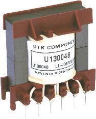
13 Pulse transformers Features Used in SCR and TRIAC starting circuits of low, medium and high powers. Wide range of standard products available. Special versions according to customers requirements Manufactured according to EN61558 and EN60950 standards Compact size Visual inspection Pinout and polarity check Value of the reference parameters ( n, Lp, Ld, Ck, Rp, Rs) Dielectric strength Applications Technical description UTK pulse transformers, normally used to drive semiconductors as thyristors and triacs, can transfer a square wave or a pulse with very short rise and fall times without appreciable distortion of the waveform. In such applications they provide both the firing pulse to the semiconductor s gate, and the isolation between the low power control circuit and the power semiconductors, according to the international standards for the safety of the transformers. UTK pulse transformers have the following characteristics. Compact construction. They are vacuum-filled and encapsulated in plastic box made with self extinguishing material UL94-HB, suitable for the application on high density PCBs. Availability in a standard temperature range ( 0+80 ) or an extended range Safe and reliable galvanic insulation Excellent magnetic coupling between the primary and secondary winding, which provides high fidelity in the transmission of the pulse having the shortest propagation times, and a low magnetizing current. Transmission of high instantaneous power values High degree of immunity from noise and interference, thanks to the low coupling capacitance between primary and secondary. Low losses. Maximum working voltage up to 1KV. Dielectric strength tests are conducted according to the international standards EN61558 and EN A wide range of standard products is available for the driving of low to high power devices. In order to satisfy specific requirements UTK Component can develop special products according to the customers' needs. Firing circuit for SCR. Resistance R2 and capacitor C1 improve the noise immunity of the driving circuit and prevent spurious triggering. Resistance R1 limits the gate current. D2 and D3 allow fast core recovery in the transformer. D1 inhibits the gate current during the demagnetization. Through the addition of the resistance R3 and capacitor C2 a double level driving pulse is obtained: a higher starting peak in order to optimise the firing of the thyristor, followed by a fall of the driving current for lower dissipation. UTK Component controls closely the production during the process and at the end of it, granting the quality and reliability of the product. The carried out tests include: UTK component pag. 2

14 Pulse transformers Reference parameters Winding ratio n Turns ratio of the primary winding to the secondary. Voltage time area udt Voltage time Integral on the secondary winding, or voltage time area. In case of application of unipolar pulse to the primary winding, udt shows the maximum permitted value for the integral of secondary voltage, to avoid saturation of the magnetic core. Expressed in Vµs. Rise time Ts Time interval calculated on the rising slope of the secondary waveform, between 10% and 90% of the peak value, with resistive load equal to Rn and driving voltage 12V with duty cycle 50%. This parameter is mainly related to the quality of the magnetic coupling between the primary and the secondary winding and with the value of the leakage inductance Ld. Pulse Peak current Maximum permitted secondary current Load Resistance Nominal load resistance Inductance Ip Rn Lp Equivalent circuit of the pulse transformer. Nominal value of inductance on primary winding. The maximum deviation from the nominal value ( tolerance) is +\-30%. Measured with LCR meter at the primary winding (Ambient temp 25 C, frequency 10KHz, drive UAC,rms=250mV). Coupling capacitance Ck Coupling capacitance between primary and secondary winding, depending on electric coupling of the coils. Low Ck values provide a high level of noise immunity to the firing circuit, preventing transmission of voltage spikes or high frequency noise coupling to the secondary and avoiding spurious triggering. Measured with LCR meter between the primary and secondary windings, with both windings shorted (frequency 10KHz, drive UAC,rms=250mV). Winding resistance Rp,Rs Resistance measured with LCR meter at the primary and secondary windings. UTK component pag. 3
15 Code n udt (µvs) Ts (µs) Ip (ma) Rn (Ω) Lp (mh) Ck (pf) Rp (Ω) Rs (Ω) Model Pin Out TI :1 300 <0, ,2 25 0,7 0,7 TI-120 A TI :1:1 300 <0, ,2 23 0,7 0,7 TI-120 B TI :1 250 <0, ,3 28 0,5 0,25 TI-120 A TI :1:1 250 <0, ,3 31 0,5 0,25 TI-120 B TI :1 150 <0, ,3 22 0,5 0,15 TI-120 A TI :1 500 < ,3 35 0,45 0,45 TI-125 A TI :1:1 500 < ,3 35 0,45 0,45 TI-125 B TI :1:1 500 < ,9 0,45 TI-125 B TI : < ,6 45 0,8 0,8 TI-125 A TI :1: < ,9 0,9 TI-125 B TI :1 300 <0, ,3 40 0,6 0,2 TI-125 A TI :1:1 300 <0, ,3 40 0,6 0,2 TI-125 B Modello Model TI-120 View pin-side ,5 3x5 ø 0,8 8 5 uscite pin out A uscite pin out B 20, , Modello Model TI-125 View pin-side 28, ,5 4x5,08 0,8x0,8 5 7 Uscite pin out A Uscite pin out B UTK component pag. 4
16 Low power switch mode transformers Features Transformers for low power and high frequency switch mode power supplies (flyback,forward and pushpull circuits) Special versions according to customers requirements Manufactured according to EN61558 and EN60950 standards Compact size Technical description If linear regulators are still predominant in low power applications (lower than 10W), where no high efficiency, low weight or volume are required, the switch mode power supply circuits have become more and more popular in the last years thanks to the many advantages they offer and to the wide availability and application of single chip control circuits at a low cost. The reduction of the weight and dimensions, the higher efficiency and the lower thermal dissipation bring to an almost unavoidable utilisation of switching circuits in portable battery applications and generally in all applications where particularly restricted weights and dimensions are required for powers up to few hundreds Watts. Other applications, becoming more and more popular, include small standby power supplies and off-line switching circuits for electronic PCBs. The most commonly used circuits topologies for such applications include flyback, forward and pushpull, which provide galvanic insulation from the mains, availability of multiple outputs and powers till few hundreds Watts. UTK produces transformers for low power switching power supplies according to the customer requirements, using standard configurations and well established methodologies to guarantee the high quality of the result. UTK can also provide qualified technical support in the design phase of the transformer, offering its competence in the selection of the materials and the most suitable production techniques. Transformers for single chip switching converters are also available. National Semiconductor SIMPLE SWITCHER ST Microelectronics VIPER 50/100 Power Integrations TOPSWITCH e TINYSWITCH UTK Component switching transformers have the following characteristics. Compact construction. They are vacuum-filled and encapsulated in plastic box made with self extinguishing material UL94-HB, suitable for the application on high density PCBs. Availability in a standard temperature range ( 0+80 ) or an extended range Multiple secondary windings Safe and reliable galvanic insulation Output power up to 200/300W Working frequency up to 500KHz UTK Component controls closely the production during the process and at the end of it, granting the quality and reliability of the product. The carried out tests include: Visual inspection Pinout and polarity check Value of the reference parameters Dielectric strength Applications Flyback circuit Forward circuit Push-Pull circuit Core selection In the following we give a table to help the designer in the core selection phase, showing the theoretical power output of a switching stage depending on the circuit topology and working frequency. Actual values may differ from the theoretical values since other factors, for example the number of the secondary windings, working voltages, circuit details, temperature rise limits, etc, are not taken into consideration. UTK component pag. 5
17 Low power switch mode transformers Theoretical power output [Watt] of a Forward converter at the frequency shown [KHz] Core Ae Ab EFD15/8/5 0,150 0,148 0,9 1,8 2,7 3,6 4,4 5,3 6,2 7,1 EFD20/10/7 0,310 0,264 3,3 6, EFD25/13/9 0,580 0, EFD30/15/9 0,690 0, EE13/7/4 0,130 0,116 0,6 1,2 1,8 2,4 3,0 3,6 4,2 4,8 EE16/8/5 0,201 0,216 1,7 3,5 5,2 6,9 8, EE20/10/6 0,335 0,350 4,7 9, EE25/13/7 0,525 0, EE30/15/7 0,600 0, EE32/16/9 0,830 0, ETD29/16/10 0,760 0, ETD34/17/11 0,971 1, ETD39/20/13 1,250 1, Theoretical power output [Watt] of a PushPull converter at the frequency shown [KHz] Core Ae Ab EFD15/8/5 0,150 0,148 1,8 3,6 5,3 7,1 8, EFD20/10/7 0,310 0,264 6, EFD25/13/9 0,580 0, EFD30/15/9 0,690 0, EE13/7/4 0,130 0,116 1,2 2,4 3,6 4,8 6,0 7,2 8,4 10 EE16/8/5 0,201 0,216 3,5 6, EE20/10/6 0,335 0,350 9, EE25/13/7 0,525 0, EE30/15/7 0,600 0, EE32/16/9 0,830 0, ETD29/16/10 0,760 0, ETD34/17/11 0,971 1, ETD39/20/13 1,250 1, Theoretical power output [Watt] of a Flyback converter at the frequency shown [KHz] Core Ae Ab EFD15/8/5 0,150 0,148 0,6 1,3 1,9 2,5 3,1 3,7 4,3 5,0 EFD20/10/7 0,310 0,264 2,3 4,6 6,9 9, EFD25/13/9 0,580 0,402 6, EFD30/15/9 0,690 0, EE13/7/4 0,130 0,116 0,4 0,8 1,3 1,7 2,1 2,5 2,9 3,4 EE16/8/5 0,201 0,216 1,2 2,5 3,6 4,8 6,1 7,3 8,5 9,7 EE20/10/6 0,335 0,350 3,3 6, EE25/13/7 0,525 0,560 8, EE30/15/7 0,600 0, EE32/16/9 0,830 0, ETD29/16/10 0,760 0, ETD34/17/11 0,971 1, NOTES 1- The table gives the theoretical power output of a converter depending on the working frequency and the circuit topology. 2- Ae and Ab respectively show the cross sectional area of the core and the winding area [cm2]. 3- Theoretical values are calculated for a peak flux density Bmax=0.16T, and a coil current density of 4A/mmq. 4 Actual values of output power differ from theoretical values as core gets larger and for higher frequencies and power. Other factors, for example skin effect and proximity effect, are not taken into consideration. At frequencies over 50/100KHz the core losses of some materials require also a reduction of the peak flux density Bmax. UTK component pag. 6
18 STANDARD BOBBINS HORIZONTAL VERSION HOLE ARRANGEMENT VIEW PIN - SIDE DIMENSIONS OPEN VERSION (AxBxH) BOX VERSION (AxBxH) VERTICAL VERSION HOLE ARRANGEMENT VIEW PIN - SIDE DIMENSIONS OPEN VERSION (AxBxH) BOX VERSION (AxBxH) EFD15/8/ ,75 3x3,75 A= 16,5 B= 15 H= 8,5 EFD20/10/ ,5 3x5 A= 21 B= 21 H= 10 EFD25/13/ ,5 4x5 A= 26 B= 26 H= EFD30/15/ x5 A= 32 B= 31 H= 13 27,5 A B H UTK component pag. 7
19 STANDARD BOBBINS HORIZONTAL VERSION HOLE ARRANGEMENT VIEW PIN - SIDE DIMENSIONS OPEN VERSION (AxBxH) BOX VERSION (AxBxH) VERTICAL VERSION HOLE ARRANGEMENT VIEW PIN - SIDE DIMENSIONS OPEN VERSION (AxBxH) BOX VERSION (AxBxH) EE13/7/4 (EF12,6) ,16 4x2,54 A= 16,5 B= 13 H= 10,5 EE16/8/5 (EF16) , x5 3x5 A= 17 B= 17 H= 12,5 A= 17,5 B= 17 H= 11,5 A= 19,5 B= 19,5 H= 15 A= 19,5 B= 19,5 H= ,89 3x3,81 A= 13 B= 18 H= 18,5 A= 14 B= 19 H= 19,5 15 EE20/10/6 (EF20) , x3,81 3x5 A= 22 B= 22 H= 17 A= 21 B= 20 H= 14 A= 24,5 B= 23 H= ,16 4x3,81 A= 17 B= 22 H= 22,5 A= 18 B= 22 H= EE25/13/7 (EF25) ,32 4x5,08 A= 25 B= 25 H= 18 A= 28,5 B= 28,5 H= 20, ,7 4x5,08 A= 19,5 B= 27,5 H= 28 A= 21 B= 28 H= 32 UTK component pag. 8
20 STANDARD BOBBINS HORIZONTAL VERSION HOLE ARRANGEMENT VIEW PIN - SIDE DIMENSIONS OPEN VERSION (AxBxH) BOX VERSION (AxBxH) VERTICAL VERSION HOLE ARRANGEMENT VIEW PIN - SIDE DIMENSIONS OPEN VERSION (AxBxH) BOX VERSION (AxBxH) EE30/15/ x5,08 A= 32 B= 34 H= x5,08 A= 20 B= 36 H= 35 22,86 15,24 EE32/16/9 (EF132) ,4 5x5,08 A= 31,5 B= 33 H= ETD29/16/ x5,08 A= 36 B= 36 H= 26 A= 38 B= 38 H= x5,08 A= 24 B= 35 H= 41 25,4 20,32 ETD34/17/ x5,08 A= 43 B= 40 H= 35 A= 45 B= 42 H= x5,08 A= 30 B= 40 H= 46 25,4 22,86 ETD39/20/13 A= 48 B= 45 H= 38 A= 51 B= 48 H= 40 A= 33 B= 45 H= 50 UTK component pag. 9
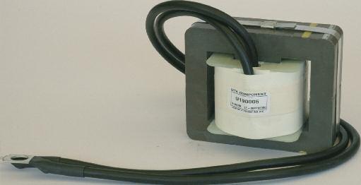
21 High power switch mode transformers Features High power transformers for high frequency inverter circuits. Special versions according to customers requirements Manufactured according to EN61558 and EN60950 standards Wounded with standard copper insulated wire, copper strip or Litz wire Applications include UPS, welding power sources, battery chargers, electric vehicles, industrial power supplies. Value of the reference parameters Dielectric strength Applications Technical description The electrical energy conversion process in high frequency inverters requires the use of power transformers in order to provide an insulating barrier from the input to the output and to raise or lower the input signal and adjust it to the required output values. These components seem to be the heaviest and bulkiest of the whole equipment. The characteristics of the power transformers often affect also the efficiency, the volume, the weight, the cost and the performance of the whole system. The design and development of power transformers consequently require a specific know how and experience. UTK produces power transformers, using standard configurations and well established methodologies to guarantee the high quality of the result. UTK can also provide qualified technical support in the design phase of the transformer, offering its competence in the selection of the materials and the most suitable production techniques. UTK Component power transformers have the following characteristics. Open construction with standard bobbins and cores, for vertical and horizontal mounting; vacuum-filled and encapsulated in plastic box for higher isolation voltage. Availability in a standard temperature range ( 0+80 ) or an extended range Wound with standard copper insulated wire, copper strip or Litz wire Low leakage inductance and low primary to secondary coupling capacitance Safe and reliable galvanic insulation Output power up to 10KW Working frequency up to 200KHz Manufactured according to the international standards EN61558 and EN UTK Component controls closely the production during the process and at the end of it, granting the quality and reliability of the product. The carried out tests include: Visual inspection Pinout and polarity check Half Bridge power converter circuit Full-Bridge power converter circuit Push-Pull power converter circuit Double ended Forward power converter circuit UTK component pag. 10
22 High power switch mode transformers Core selection In the following we give a table to help the designer in the core selection phase, showing the theoretical power output of a switching stage depending on the circuit topology and working frequency. Actual values may differ from the theoretical values since other factors, for example the number of the secondary windings, working voltages, circuit details, temperature rise limits, etc, are not taken into consideration. Theoretical power output [Watt] of a Forward converter at the frequency shown [KHz] Core Ae Ab ETD39/20/13 1,250 1, ETD44/22/15 1,740 2, ETD49/25/16 2,110 2, EE42/21/15 1,780 1, EE42/21/20 2,340 1, EE55/28/21 3,540 2, EE55/28/25 4,200 3, EE65/32/27 5,320 4, EE70/33/32 6,830 4, Theoretical power output [Watt] of a PushPull converter at the frequency shown [KHz] Core Ae Ab ETD39/20/13 1,250 1, ETD44/22/15 1,740 2, ETD49/25/16 2,110 2, EE42/21/15 1,780 1, EE42/21/20 2,340 1, EE55/28/21 3,540 2, EE55/28/25 4,200 3, EE65/32/27 5,320 4, EE70/33/32 6,830 4, Theoretical power output [Watt] of a Half/full Bridge converter at the frequency shown [KHz] Core Ae Ab ETD39/20/13 1,250 1,740 2, ETD44/22/15 1,740 2, ETD49/25/16 2,110 2, EE42/21/15 1,780 1, EE42/21/20 2,340 1, EE55/28/21 3,540 2, EE55/28/25 4,200 3, EE65/32/27 5,320 4, EE70/33/32 6,830 4, NOTES 1- The table gives the theoretical power output of a converter depending on the working frequency and the circuit topology. 2- Ae and Ab respectively show the cross sectional area of the core and the winding area [cm2]. 3- Theoretical values are calculated for a peak flux density Bmax=0.16T, and a coil current density of 4A/mmq. 4- Actual values of output power differ from theoretical values as core gets larger and for higher frequencies and power. Other factors, for example skin effect and proximity effect, are not taken into consideration. At frequencies over 50/100KHz the core losses of some materials require also a reduction of the peak flux density Bmax. UTK component pag. 11
23 STANDARD BOBBINS HORIZONTAL VERSION HOLE ARRANGEMENT VIEW PIN - SIDE DIMENSIONS OPEN VERSION (AxBxH) BOX VERSION (AxBxH) VERTICAL VERSION HOLE ARRANGEMENT VIEW PIN - SIDE DIMENSIONS OPEN VERSION (AxBxH) BOX VERSION (AxBxH) A= 48 B= 45 H= 38 A= 51 B= 48 H= 40 A= 33 B= 45 H= 50 ETD49/25/16 ETD44/22/15 ETD39/20/13 A= 52 B= 50 H= 40 A= 55 B= 53 H= 43 A= 35 B= 50 H= 55 A= 57 B= 54 H= 43 A= 60 B= 57 H= 46 A= 36 B= 55 H= 59 UTK component pag. 12
24 STANDARD BOBBINS HORIZONTAL VERSION HOLE ARRANGEMENT VIEW PIN - SIDE DIMENSIONS OPEN VERSION (AxBxH) VERTICAL VERSION HOLE ARRANGEMENT VIEW PIN - SIDE DIMENSIONS OPEN VERSION (AxBxH) 9 10 EE42/21/ x5 A= 45 B= 43 H= x5 A= 33 B= 46 H= , EE42/21/ x5 A= 45 B= 43 H= x5 A= 38 B= 48 H= 46 27,5 7 8 EE55/28/ x5 A= 56 B= 56 H= A B H UTK component pag. 13
25 STANDARD BOBBINS HORIZONTAL VERSION HOLE ARRANGEMENT VIEW PIN - SIDE DIMENSIONS OPEN VERSION (AxBxH) VERTICAL VERSION HOLE ARRANGEMENT VIEW PIN - SIDE DIMENSIONS OPEN VERSION (AxBxH) 7 8 EE55/28/ x5 A= 56 B= 56 H= EE65/32/ x5 A= 66 B= 66 H= EE70/33/ x5 A= 66 B= 71 H= UTK component pag. 14
26 Drive transformers Features Used in high frequency drive circuits for MOSFETs and IGBTs. Wide range of standard products available. Special versions according to customers requirements Manufactured according to EN61558 and EN60950 standards Compact size Technical description Following the fast growth of the semiconductor technology, power electronic devices like MOSFETs and IGBTs have seen big changes during the past years. Modern semiconductor components allow switching of high powers with higher working voltages, higher operating frequencies and lower losses. At the same time they require complex and performing new driving circuits. UTK Component drive transformer are an outgrowth of the standard pulse transformers, optimised in the choice of the materials and manufacturing techniques to give superior performance in terms of switching speed, low transition times and form fidelity, in MOSFET and IGBT drive circuits. They give also safe and reliable galvanic isolation, according to international standards, with high working voltages. UTK drive transformers have the following characteristics. Compact construction. They are vacuum-filled and encapsulated in plastic box made with self extinguishing material UL94-HB, suitable for the application on high density PCBs. Availability in a standard temperature range ( 0+80 ) or an extended range Safe and reliable galvanic insulation Excellent magnetic coupling between the primary and secondary winding, which provides high fidelity in the transmission of the driving pulse Low magnetising current. Transmission of high instantaneous power values Working frequencies up to 200 KHz, with near-zero propagation times Low losses. Maximum working voltage up to 1KV. Dielectric strength tests are conducted according to the international standards EN61558 and EN A wide range of standard products is available for the driving of low to high power devices. In order to satisfy specific requirements UTK Component can develop special products according to the customers' needs. UTK Component controls closely the production during the process and at the end of it, granting the quality and reliability of the product. The carried out tests include: Visual inspection Pinout and polarity check Value of the reference parameters ( n, Lp, Ld, Ck, Rp, Rs) Dielectric strength Applications Transformer coupled BJT driving circuit. Transformer coupled MOSFET driving circuit. Transformer coupled MOSFET driving circuit, with a low impedance path for fast gate turn-off. UTK component pag. 15


. Lp Pulse Leakage inductance Ld Leakage inductance measured at the primary winding.")
27 Drive transformers avoiding spurious triggering. Measured with LCR meter between the primary and secondary windings, with both windings shorted (frequency 10KHz, drive UAC,rms=250mV). Winding resistance Rp,Rs Resistance measured with LCR meter at the primary and secondary windings. Dual output gate drive circuit for MOSFETs and IGBTs. Reference parameters Winding ratio n Turns ratio of the primary winding to the secondary. Voltage time area udt Voltage time Integral on the secondary winding, or voltage time area. In case of application of unipolar pulse to the primary winding, udt shows the maximum permitted value for the integral of secondary voltage, to avoid saturation of the magnetic core. Expressed in Vµs. Inductance Nominal value of inductance on primary winding. The maximum deviation from the nominal value ( tolerance) is +\-30%. Measured with LCR meter at the primary winding (Ambient temp 25 C, frequency 10KHz, drive UAC,rms=250mV). Lp Pulse Leakage inductance Ld Leakage inductance measured at the primary winding. It gives indications concerning the quality of the magnetic coupling between primary and secondary winding. A low value of leakage inductance provides high fidelity in the pulse transmission with short transition and propagation times. Measured with LCR meter at the primary winding, with secondary windings shorted (Ambient temp 25 C, frequency 10KHz, drive UAC,rms=250mV). Equivalent circuit. Coupling capacitance Ck Coupling capacitance between primary and secondary winding, depending on electric coupling of the coils. Low Ck values provide a high level of noise immunity to the driving circuit, preventing transmission of voltage spikes or high frequency noise coupling to the secondary and UTK component pag. 16
28 Code n udt (µvs) Lp (µh) Ld (µh) Ck (pf) Rp (mω) Rs (mω) Model Pin Out TI :1: , TI-116 C TI : , TI-116 A TI :1,2:1, , TI-116 C TI :1, , TI-116 A TI : , TI-116 A TI :1: , TI-116 B TI : , TI-116 A TI :1: , TI-116 C TI :1, , TI-116 A TI :1,3:1, , TI-116 C TI :1: , TI-116 C TI : , TI-116 A TI ,4: , TI-116 A TI ,4:1: , TI-116 B TI :1,36:1, , TI-116 C TI :1, , TI-116 A TI :1,7:1, , TI-116 C TI :1: , TI-116 B TI : , TI-116 A TI :1, , TI-116 A TI ,3:1, , TI-116 B TI :1, , TI-116 A TI :1: TI-116 C TI ,4: , TI-116 A TI ,4:1: , TI-116 C TI : TI-120 A TI :1: , TI-120 B TI : , TI-120 A TI :1: TI-120 B TI :1, TI-120 A TI :1,2:1, TI-120 B TI : TI-120 A TI :1: TI-120 B TI : , TI-120 A TI :1: TI-120 B TI :4: , TI-120 B TI : , TI-120 C TI :2,2:2, , TI-120 B TI : , TI-120 A TI :1: , TI-120 B TI : , TI-120 A TI :1: , TI-120 B 12, Modello Model TI ,5 View pin-side ,5 15 3x5 ø 0, uscite pin out A uscite pin out B uscite pin out C 8 1 Modello Model TI View pin-side ,5 3x5 ø 0,8 8 5 uscite pin out A uscite pin out B 5 3 uscite pin out C UTK component pag. 17
29 Current sense transformers Features Current sense transformers used to detect switching currents in power semiconductors for control and monitoring functions or in current limiting circuits. Wide range of standard products available. Special versions according to customers requirements Manufactured according to EN61558 and EN60950 standards Compact size A wide range of standard products is available for the most common applications. In order to satisfy specific requirements UTK Component can develop special products according to the customers' needs. UTK Component controls closely the production during the process and at the end of it, granting the quality and reliability of the product. The carried out tests include: Visual inspection Pinout and polarity check Value of the reference parameters Dielectric strength Technical description UTK current sense transformers are normally used to detect switching currents in power semiconductors, for control, monitoring and protection purposes or to read the current in current mode control circuits. They are necessary in all applications where a galvanic insulation between the measured current and the measuring circuit is required. Unlike the current transformers used for measurement application, these devices don t give very high accuracy. Their main application concerns in fact other factors, as for example cost and circuit simplicity, since they have to detect peak values or current trends rather than absolute values with the utmost precision. In addition to the galvanic insulation between the power line and the control circuit, the current sensors give many advantages compared with resistive current sensing. The lower power dissipation of a current sense transformer allows a much higher signal level, improving the signal to noise environment of the control system. Unlike resistive shunts, where the resistance to inductance ratio is very poor, they also allow high working frequencies. UTK Component current transformers have the following characteristics. Compact construction. They are vacuum-filled and encapsulated in plastic box made with self extinguishing material UL94-HB, suitable for the application on high density PCBs. Availability in a standard temperature range ( 0+80 ) or an extended range High turns ratio, from 1:50 to 1:800 Primary current from 20 to 100A High working frequency (from 40 KHz to 200KHz) Safe and reliable galvanic insulation Maximum working voltage up to 1KV. Dielectric strength tests are conducted according to the international standards EN61558 and EN Low losses. Applications Current sense transformer and secondary circuit for the measure of unipolar pulses. Voltage on resistor R2 gives a good measure of the primary current. Diode D1 blocks inverse voltage during core demagnetization. Resistor R1, with its high value, allows a fast core recovery to detect very closely spaced pulses without core saturation. Current sense transformer and secondary circuit for the measure of bipolar pulses. The circuit can detect positive and negative current pulses thanks to diode bridge. UTK component pag. 18
30 Current sense transformers Primary current Ip Nominal value of the primary current, mainly related to the cross sectional area of the windings. Voltage time area udt Current measure circuit in a single-ended forward power conversion stage. Voltage time Integral on the secondary winding, or voltage time area. In case of measure of unipolar pulses, udt shows the maximum permitted value for the integral of secondary voltage, to avoid saturation of the magnetic core. Expressed in Vµs. Measuring circuits should provide adequate mechanisms for core demagnetization, also with very closely spaced pulses. Secondary Inductance Ls Current measure circuit in a full-bridge power conversion stage. Reference parameters Winding ratio Turns ratio of the primary winding to the secondary. The primary winding is usually a single turn of high cross sectional area supplied by the user. A high winding ratio provides high secondary inductance, more accurate measures and lower insertion losses on the primary circuit. n Nominal value of inductance on secondary winding. The maximum deviation from the nominal value ( tolerance) is +\-25%. Measured with LCR meter at the primary winding (Ambient temp 25 C, frequency 10KHz, drive UAC,rms=250mV). The higher the inductance value, the lower the magnetizing current and more accurate the measure. Usually a magnetizing current equal to 10% of the primary current at the end of on time, gives a high quality measure in most applications. Winding resistance Resistance measured with LCR meter at the secondary winding. Rs Code n Ip (A) udt (µvs) Ls (mh) Rs (Ω) Model Pin Out TA : ,16 TA-314 A TA : ,63 TA-314 A TA : ,85 TA-314 A TA : ,16 TA-316 A TA : ,63 TA-316 A TA : ,85 TA-316 A TA : ,46 TA-326 A-Pin TA : ,46 TA-326 A-faston TA : ,00 TA-326 A-Pin TA : ,00 TA-326 A-faston TA : ,35 TA-331 A-Pin TA : ,35 TA-331 A-faston TA : ,10 TA-331 A-Pin TA : ,10 TA-331 A-faston TA * 1: ,95 TA-116 A TA * 1: ,50 TA-116 A TA * 1: TA-116 A TA * 1: TA-116 A TA * 1: ,5 0,6 TA-120 A TA * 1: ,1 TA-120 A UTK component pag. 19
31 Current sense transformers UTK component pag. 20
32 Switching inductors Features Storage and filter chokes for low power switch mode power supplies. Wide range of standard products available. Wound on toroidal core, for vertical and horizontal PCB mounting. Compact size Applications Output choke in a Forward converter. Technical description Linear storage chokes are widely used in switching power supply circuits which operate in forward mode. Their task is to level the output current by storing the energy during the conduction time of the power semiconductors and by releasing it during the off time. The filter inductors are normally used in output circuits of the switching power supplies in order to reduce the voltage and current ripple. In both cases the inductors operate with high DC currents. Buck DC/DC power conversion stage. UTK switching inductors are designed for high storage energy values and low losses at high switching frequencies. In order to minimize the physical dimensions they are wound on iron powder toroidal cores and operate with flux density close to saturation. The windings on a single layer provide low interwinding capacitance and good noise immunity up to high frequencies. A wide range of standard products is available for the most common applications. In order to satisfy specific requirements UTK Component can develop special products according to the customers' needs. Storage and filter chokes for single-chip DC/DC converters of the National Semiconductor SIMPLE SWITCHER family (LM259X e LM267X) are also available. UTK Component switching inductors have the following characteristics. Compact size, wound on iron powder toroidal cores, for vertical and horizontal PCB mounting. Nominal currents from 0.25A to 10 A. Inductance values from 15µH to 10000mH High working frequency, up to 100KHz Low losses UTK Component controls closely the production during the process and at the end of it, granting the quality and reliability of the product. The carried out tests include: Visual inspection Value of the reference parameters Boost DC/DC power conversion stage. Reference parameters Inductance Nominal value of the inductance without DC current. Measured with LCR meter (Ambient temp 25 C, frequency 10KHz, drive UAC,rms=0.5Vac). Tolerance +/- 25%. Nominal current Nominal DC offset current. Winding resistance Winding resistance measured with LCR meter. Frequency Maximum working frequency. Ln In R Fmax UTK component pag. 21
33 Code In (A) Ln (µh) f max (KHz) Dimension (De x Di x H) Terminals (ø) B x6.5x B x6.5x B x10x B x6.5x B x10x B x11x B x7x B x9.5x B x11x B x11.5x B x18.5x B x6.8x B x11x B x12.5x B x12.8x B x18x B x20x B x22.5x B x6.5x B x10.5x B x11.5x B x12.5x B x18x B x19.5x B x22.5x B x20x B x10x B x11.5x B x12x B x17x B x19x B x22x B x19x B x19x B x9.5x B x11x B x11.5x B x B x19x B x21x B x21x UTK component pag. 22
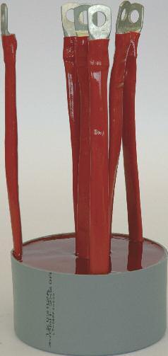
34 50-60Hz Current transformers Features Current sense transformers used to detect 50-60Hz alternating currents up to 600A Wide range of standard products available. Special versions according to customers requirements Manufactured according to EN61558 and EN60950 standards Pinout and polarity check Value of the reference parameters Dielectric strength Reference parameters Primary and secondary current Ip/Is RMS value of the alternating current on the primary (Ip) and secondary (Is) windings. Technical description Current transformers intended for measuring alternating currents at 50-60Hz, for overcurrent detection and protection in industrial applications. Load resistance Nominal load resistance on the secondary circuit. Output voltage Ru Vu The standard products range include transformers from 25A to 600A. Their toroidal structure makes them easy to insert into cables or other parts of the circuits without having to interrupt or modify the circuit itself. The conductor carrying the current to be measured serves as the one turn primary while the secondary is wound around the core. The voltage at the load resistor is proportional to the current flowing in the primary winding. Sensitivity can be enhanced by increasing the number of primary turns. Voltage measured at the load, proportional to the primary current value. UTK current transformers provide the galvanic insulation and dielectric strength adequate for separation from a.c. mains potentials. UTK Component current transformers have the following characteristics. Compact construction. They are vacuum-filled and encapsulated in plastic box made with self extinguishing material UL94-HB, suitable for the application on high density PCBs. Availability in a standard temperature range ( 0+85 ) or an extended range Wound on toroidal cores Primary current from 25 to 600A Working frequency 50-60Hz Safe and reliable galvanic insulation (4KV) Low losses. A wide range of standard products is available for the most common applications. In order to satisfy specific requirements UTK Component can develop special products according to the customers' needs. UTK Component controls closely the production during the process and at the end of it, granting the quality and reliability of the product. The carried out tests include: Visual inspection UTK component pag. 23

35 50-60Hz Current transformers IP c.a. 1 IP c.a. 1 IP c.a. 1 2 IP 3 IS Ru Vu Circuit 1 Circuit 2 Circuit 3 Connection diagram Code Ip/Is Circuit Model Output Ru Test Voltage Vu Accuracy TA /0,05 A 1 TA-526 PIN 40 Ω 4 KVac 2 Vac 2,1 % TA /0,05 A 1 TA Ω 4 KVac 2 Vac 2,1 % TA /0,05 A 1 TA Ω 4KVac 2 Vac 2,0 % TA /0,05 A 1 TA-531 PIN 40 Ω 4KVac 2 Vac 2,0 % TA /0,05 A 1 TA-531 PIN 80 Ω 4 KVac 4 Vac 1,0 % TA /0,05 A 1 TA Ω 4 KVac 4 Vac 1,0 % TA /0,2 A 2 TA Ω 4 KVac 4 Vac 0,8 % TA /0,2 A Ω 4 KVac 4 Vac 2,5 % 50/0,2 A 3 TA Ω 4 KVac 4 Vac 1,5 % 100/0,2 A Ω 4 KVac 4 Vac 0,8 % TA /0,1 A 2 TA Ω 4 KVac 2 Vac 0,4 % TA /0,2 A 2 TA Ω 4 KVac 2 Vac 0,4 % TA /0,4 A 2 TA Ω 4 KVac 8 Vac 0,4 % TA /0,4 A Ω 4 KVac 8 Vac 1,0 % 400/0,4 A 3 TA Ω 4 KVac 8 Vac 0,4 % 600/0,4 A Ω 4 KVac 8 Vac 0,2 % TA /0,2 A 2 TA Ω 4 KVac 4 Vac 0,2 % TA /0,2 A Ω 4 KVac 4 Vac 0,5 % 300/0,2 A 3 TA Ω 4 KVac 4 Vac 0,3 % 400/0,2 A Ω 4 KVac 4 Vac 0,2 % TA /0,6 A 2 TA Ω 4 KVac 6 Vac 0,2 % TA /0,2 A 2 TA Ω 4 KVac 4 Vac 0,5 % UTK component pag. 24
36 50-60Hz Current transformers UTK component pag. 25
37 Custom designed inductive components To meet customer's special requirements, UTK Component designs, develops and produces special inductive components, offering its experience and technological competence and a high qualified designing staff. In the following you can find a technical data sheet including reference parameters useful for the design of pulse and drive transformers, current sense transformers, switching inductors and transformers for low and high power. To request the design of a special product, please fill in the form and sketch the application circuit diagram. Power conversion transformers Data sheet Switching power supply circuit used Primary voltage (Vdc) min.: max.: Primary inductance (mh) Tolerance on inductance (%) Primary current r.m.s. (ma) Max primary over current (ma) Working frequency (khz) Switching time (µs) ton max.: ton min.: Rated power (W) For each secondary Peak voltage (V) Peak current (A) RMS current (A) Turns ratio Output power (W) Working voltage between different windings (V) Test voltage between different windings (V) Operating temperature ( C) Open construction or box version Size limitations (mm) Standards to comply with Quantity Target price UTK component pag. 26
38 50/60 Hz Current transformers Data sheet Primary current r.m.s. (ma) Max primary over current (ma) Working frequency (khz) Secondary inductance (mh) Load resistance (Ω) Accuracy (%) Working voltage between primay and secondary (V) Test voltage between primay and secondary (V) Operating temperature ( C) Size limitations (mm) Passing through hole model (show the dimensions) Inside primary wire model Standards to comply with Quantity Target price HF Current sense transformers Data sheet Primary current r.m.s. (ma) Max primary over current (ma) Working frequency (khz) Secondary inductance (mh) Load resistance (Ω) Primary vs. secondary current linearity (%) Working voltage between primay and secondary (V) Test voltage between primay and secondary (V) Operating temperature ( C) Size limitations (mm) Passing through hole model (show the dimensions) Inside primary wire model Standards to comply with Quantity Target price UTK component pag. 27
39 Pulse and drive transformers Data sheet Turns ratio Min. voltage time area at winding (µvs) Primary inductance (mh) Tollerance on inductance (%) Primary current r.m.s. (ma) Max. primary over current (ma) Working frequency (khz) Max. coupling capacity between windings (pf) Max. admitted value of leakage inductance (µh) Working voltage between different windings (V) Test voltage between different windings (V) Operating temperature ( C) Size limitations (mm) Standards to comply with Quantity Target price Inductors Data sheet Inductance value at nominal rated current (µh) Tollerance on inductance (%) Rated current r.m.s. (ma) Max. over current (ma) Working voltage (V) Working frequency (khz) Rated power (W) Operating temperature ( C) Open construction or box version Size limitations (mm) Standards to comply with Quantity Target price UTK component pag. 28
40 Circuit
41 Rapresentatives UTK component Info: Sales department: Purchase department: Technical department: Quality department:
 - Italy Tel.")
42 w w w. u t k c o m p o n e n t. c o m Via del Progresso, 35/ Noventa Vicentina - (Vicenza) - Italy Tel. 0039(0) Fax 0039(0)
COMPLIANT Common Mode Chokes - UU9.8 & UU10.5 Series
 Document FR00 COMPLIANT Common Mode Chokes - UU9.8 & UU0.5 Series Order Code MCU 000 MCU 0002 Core Mounting Inductance mh (Min) UU9.8 Series Current Rating ma (steady state) 350 350 Leakage DC Inductance
Ph: +1 (919) Page 1 OTHER PRODUCTS
 Page 1 OTHER PRODUCTS") POWER CONVERTERS CLAMPS OTHER PRODUCTS ELECTRONIC BOARDS HEATSINKS TRIGGERING BOARDS The image cannot be displayed. Your computer may not have enough memory to open the image, or the image may have been
POWER CONVERTERS CLAMPS OTHER PRODUCTS ELECTRONIC BOARDS HEATSINKS TRIGGERING BOARDS The image cannot be displayed. Your computer may not have enough memory to open the image, or the image may have been
TRANSFORMERS & INDUCTORS MYRRA....Of course!
 TRANSFORMERS & INDUCTORS...Of course! COMPANY PROFILE Myrra is a major supplier in high quality for electronics components. Myrra has established a worldwide reputation. Myrra design and manufacture high-quality
CONTENTS 2/ /7 8/9 10/11 12/13 14/15 16/17 18/19 20/21 22/23 24/25 26/27 28/29 30/31 32/ Contact Us 38
 CONTENTS Market Sectors Company Profile Planar Technology Product Range Overview Size 10 MAX 1kW Size 195 MAX 1.5kW Size 225 MAX 2kW Size 20 MAX 2kW Size 50 MAX 6.5kW Size 500 MAX 10kW Size 510 MAX 10kW
Data Sheet. Hall effect transducers, current and voltage
 Data Pack E Issued March 200 232-20 Data Sheet Hall effect transducers, current and voltage This data sheet covers the following products: RS stock no. Type of transducer 28-3 Multi-range current, PCB
Filters and Ring Core Chokes
 Filters and Ring Core Chokes Description FP Series L Series LP Series These Filters and chokes are designed to reduce input interference and/or output ripple voltages occurring in applications with switched
TRANSFORMERS CHASSIS TANSFORMERS FERRITE ROD 2328 LIGHTING TRANSFORMERS 2328 TOROIDAL TRANSFORMERS 2327 TRANSFORMERS
 TRANSFORMERS PULSE TRANSFORMER DAVID USE PHOTO SD0010 AUDIO TRANSFORMER CHASSIS TRANSFORMER TOROIDAL TRANSFORMER LIGHTING TRANSFORMER DAVID USE PHOTO SD0010 CHASSIS TANSFORMERS 2325-2328 FERRITE ROD 2328
A New Concept of Power Quality Monitoring
 A New Concept of Power Quality Monitoring Victor Anunciada 1, Hugo Ribeiro 2 1 Instituto de Telecomunicações, Instituto Superior Técnico, Lisboa, Portugal, avaa@lx.it.pt 2 Instituto de Telecomunicações,
INSTITUTE OF AERONAUTICAL ENGINEERING (Autonomous) Dundigal, Hyderabad
 Dundigal, Hyderabad") I INSTITUTE OF AERONAUTICAL ENGINEERING (Autonomous) Dundigal, Hyderabad-000 DEPARTMENT OF ELECTRICAL AND ELECTRONICS ENGINEERING TUTORIAL QUESTION BANK Course Name : POWER ELECTRONICS Course Code : AEE0
I INSTITUTE OF AERONAUTICAL ENGINEERING (Autonomous) Dundigal, Hyderabad-000 DEPARTMENT OF ELECTRICAL AND ELECTRONICS ENGINEERING TUTORIAL QUESTION BANK Course Name : POWER ELECTRONICS Course Code : AEE0
I-TECH INDUCTIVE TECHNOLOGIES, INC.
 INDUCTIVE TECHNOLOGIES, INC. n Toroidal and Pot Core Inductors n Pot Core Flyback Transformers n Drum Core Power Inductors n Surface Mount Power Inductors n Current Sense Transformers n T1/CEPT/ISDN Primary
The Reliable Source... FERROPERM. Inductors. Transformers
 The Reliable Source... FERROPERM for High Quality Inductors and Transformers INDUCTORS AND TRANSFORMERS from FERROPERM UK Ltd. FERROPERM offers a manufacturing capability for the production of most types
Shielded Power Inductors
 Shielded Power Inductors MN509 Shielded inductor with minimum EMI Minimum power loss Non standard values available Low DC resistance Flat top for SMT operations Specifications Inductance tested at 100KHz
3A Step-Down Voltage Regulator
 3A Step-Down Voltage Regulator DESCRIPITION The is monolithic integrated circuit that provides all the active functions for a step-down(buck) switching regulator, capable of driving 3A load with excellent
Efficiency (typ.) (Range) Load. Output Current Input Current Reflected Ripple
 (Range) Load. Output Current Input Current Reflected Ripple") FEATURES Highest Power Density 1" x 1" x 0.4" Shielded Metal Package Ultra Wide 4:1 Input Range Excellent Efficiency up to % Operating Temp. Range - C to + C Optional Heatsink I/O-isolation Voltage 10VDC
FEATURES Highest Power Density 1" x 1" x 0.4" Shielded Metal Package Ultra Wide 4:1 Input Range Excellent Efficiency up to % Operating Temp. Range - C to + C Optional Heatsink I/O-isolation Voltage 10VDC
Accessories Filter & Ring Core Chokes FP, L and LP Series
 Description These Filters and chokes are designed to reduce input interference and/or output ripple voltages occurring in applications with switched mode power supplies. Since all our filters contain a
Realisation of the galvanic isolation in customer-end DC to AC inverters for the LVDC distribution
 Realisation of the galvanic isolation in customer-end DC to AC inverters for the LVDC distribution Background: The electric distribution network in Finland has normally voltage levels of 20 kv and 400
DC/DC Converter 9 to 36Vdc and 18 to 75Vdc input voltage, 20 Watt Output Power; 3.3 to 15Vdc Single Output and ±12Vdc to ±15Vdc Dual Output
 THN 20WI Series Application Note DC/DC Converter 9 to 36Vdc and 18 to 75Vdc input voltage, 20 Watt Output Power; 3.3 to 15Vdc Single Output and ±12Vdc to ±15Vdc Dual Output Pending Applications Wireless
CRL2 Series. Isolated 2W Single Output DC/DC Converters FEATURES PRODUCT OVERVIEW
 www.murata-ps.com CRL2 Series SELECTION GUIDE Order Code Nominal Input Voltage Output Voltage Output Current Input Current at Rated Load Load Regulation (Typ) Load Regulation (Max) Ripple & Noise (Typ)
Calhoon MEBA Engineering School. Study Guide for Proficiency Testing Industrial Electronics
 Calhoon MEBA Engineering School Study Guide for Proficiency Testing Industrial Electronics January 0. Which factors affect the end-to-end resistance of a metallic conductor?. A waveform shows three complete
Lecture 19 - Single-phase square-wave inverter
 Lecture 19 - Single-phase square-wave inverter 1. Introduction Inverter circuits supply AC voltage or current to a load from a DC supply. A DC source, often obtained from an AC-DC rectifier, is converted
P2 Power Solutions Pvt. Ltd. P2 Power Magnetics. Quality Power within your Reach. An ISO 9001:2008 Company
 P2 Power Solutions Pvt. Ltd. An ISO 9001:2008 Company Quality Power within your Reach P2 Power Magnetics P2 Power Solutions Pvt. Ltd. P2 Power Solutions Pvt. Ltd. provides EMC and power quality solutions,
SELECTION GUIDE. Nominal Input Voltage Output Voltage. Output Current
 www.murata-ps.com SELECTION GUIDE Order Code Nominal Input Voltage Output Current Input Current at Rated Load Load Regulation (Typ) Load Regulation (Max) Ripple & Noise (Typ) 1 Ripple & Noise (Max) 1 Efficiency
TSTE25 Power Electronics. Lecture 6 Tomas Jonsson ISY/EKS
 TSTE25 Power Electronics Lecture 6 Tomas Jonsson ISY/EKS 2016-11-15 2 Outline DC power supplies DC-DC Converter Step-down (buck) Step-up (boost) Other converter topologies (overview) Exercises 7-1, 7-2,
COMPONENTS MODULES CORES
 COMPONENTS MODULES CORES 211 SUMIDA Components & Modules GmbH Dr. Hans-Vogt-Platz 1 D-9413 Obernzell Phone: ++49/85 91/937- Fax: ++49/85 91/937-3 E-Mail: contact@sumida-eu.com Internet: www.sumida-eu.com
Amorphous Magnetic Components & Applications
 Amorphous카다로그최종_3 10..3 3:3 PM 페이지1 www.amocore.co.kr Mag-Amp hoke ommon Mode hoke of o-based Mag-Amp hoke Reduce in size permeability Reduce the winding turns D resistance core loss power consumption
LM78S40 Switching Voltage Regulator Applications
 LM78S40 Switching Voltage Regulator Applications Contents Introduction Principle of Operation Architecture Analysis Design Inductor Design Transistor and Diode Selection Capacitor Selection EMI Design
PE Electrical Machine / Power Electronics. Power Electronics Training System. ufeatures. } List of Experiments
 Electrical Machine / Power Electronics PE-5000 Power Electronics Training System The PE-5000 Power Electronics Training System consists of 28 experimental modules, a three-phase squirrel cage motor, load,
Title. Description. Date 16 th August, Revision 1.1 RD W Telecoms DC/DC PSU Input : 37Vdc to 60Vdc Output : 32V/10A
 Title Description RD008 320W Telecoms DC/DC PSU Input : 37Vdc to 60Vdc Output : 32V/10A Date 16 th August, 2007 Revision 1.1 WWW.ConverterTechnology.CO.UK RD008 320W Push-Pull Converter August 16, 2007
COOPERATIVE PATENT CLASSIFICATION
 CPC H H02 COOPERATIVE PATENT CLASSIFICATION ELECTRICITY (NOTE omitted) GENERATION; CONVERSION OR DISTRIBUTION OF ELECTRIC POWER H02M APPARATUS FOR CONVERSION BETWEEN AC AND AC, BETWEEN AC AND DC, OR BETWEEN
Fundamentals of Power Electronics
 Fundamentals of Power Electronics SECOND EDITION Robert W. Erickson Dragan Maksimovic University of Colorado Boulder, Colorado Preface 1 Introduction 1 1.1 Introduction to Power Processing 1 1.2 Several
Chapter 10 Switching DC Power Supplies
 Chapter 10 Switching One of the most important applications of power electronics 10-1 Linear Power Supplies Very poor efficiency and large weight and size 10-2 Switching DC Power Supply: Block Diagram
SELECTION GUIDE. Nominal Input Voltage Output Voltage. Output Current
 www.murata-ps.com CRV2 Series SELECTION GUIDE Order Code Nominal Input Voltage Output Voltage Output Current Input Current at Rated Load Load Regulation (Typ) Load Regulation (Max) Ripple & Noise (Typ)
For the electronic measurement of current: DC, AC, pulsed..., with galvanic separation between the primary and the secondary circuit.
 Current transducer CKSR series N = 6, 5, 25, 5 A Ref: CKSR 6-NP, CKSR 5-NP, CKSR 25-NP, CKSR 5-NP For the electronic measurement of current: DC, AC, pulsed..., with galvanic separation between the primary
AUTOMOTIVE CURRENT TRANSDUCER HAH3DR 700-S00
 AUTOMOTIVE CURRENT TRANSDUCER HAH3DR 700-S00 Introduction The HAH3DR family, a tri-phase tranducer is for the electronic measurement of DC, AC or pulsed s in high power automotive applications with galvanic
Gate Drive Optimisation
 Gate Drive Optimisation 1. Background Driving of gates of MOSFET, IGBT and SiC/GaN switching devices is a fundamental requirement in power conversion. In the case of ground-referenced drives this is relatively
Aerovox Corp. Type RBPS IGBT Snubber Capacitor Modules Direct Mount and Board Level IGBT Capacitor Modules RoHS Compliant Highlights
 Direct Mount and Board Level IGBT Capacitor Modules Type RBPS IGBT snubber capacitor modules for power electronics can be mounted directly onto the IGBT or mounted as a board level product for protection
NCS1 Series Isolated 1W 4:1 Input Single Output DC/DC Converters
 NCS1 Series SELECTION GUIDE FEATURES UL 9 recognised 4:1 Wide range voltage input Operating temperature range -4 C to 15 C with derating 1kVDC Isolation Hi Pot Test 3.3V, 5V & 12V outputs No electrolytic
6. Explain control characteristics of GTO, MCT, SITH with the help of waveforms and circuit diagrams.
 POWER ELECTRONICS QUESTION BANK Unit 1: Introduction 1. Explain the control characteristics of SCR and GTO with circuit diagrams, and waveforms of control signal and output voltage. 2. Explain the different
MER1 Series 1kVDC Isolated 1W Single Output DC/DC Converters
 www.murata-ps.com MER1 Series SELECTION GUIDE Order Code Nominal Input Voltage Output Voltage Output Current Input Current at Rated Load Load Regulation (Typ) Load Regulation (Max) Ripple & Noise (Typ)
Positive to Negative Buck-Boost Converter Using LM267X SIMPLE SWITCHER Regulators
 Positive to Negative Buck-Boost Converter Using LM267X SIMPLE SWITCHER Regulators Abstract The 3rd generation Simple Switcher LM267X series of regulators are monolithic integrated circuits with an internal
For the electronic measurement of current: DC, AC, pulsed..., with galvanic isolation between the primary and the secondary circuit.
 Current Transducer CASR series I PN = 6, 5, 25, 5 A Ref: CASR 6-NP, CASR 5-NP, CASR 25-NP, CASR 5-NP For the electronic measurement of current: DC, AC, pulsed..., with galvanic isolation between the primary
25 Watt DC/DC converter using integrated Planar Magnetics
 technical note 25 Watt DC/DC converter using integrated Planar Magnetics Philips Components 25 Watt DC/DC converter using integrated Planar Magnetics Contents Introduction 2 Converter description 3 Converter
600 V IL V IL4108 Zero Voltage Crossing Detector Triac Optocoupler
 FEATURES High Input Sensitivity I FT =.0 ma, PF=.0 I FT =.0 ma, PF.0 00 ma On-State Current Zero Voltage Crossing Detector 00/800 V Blocking Voltage High Static dv/dt 0 kv/µs Inverse Parallel SCRs Provide
Glossary of Common Magnetic Terms
 Glossary of Common Magnetic Terms Copyright by Magnelab, Inc. 2009 Air Core A term used when no ferromagnetic core is used to obtain the required magnetic characteristics of a given coil. (see Core) Ampere
AT7450 2A-60V LED Step-Down Converter
 FEATURES DESCRIPTION IN Max = 60 FB = 200m Frequency 52kHz I LED Max 2A On/Off input may be used for the Analog Dimming Thermal protection Cycle-by-cycle current limit I LOAD max =2A OUT from 0.2 to 55
Introduction. Introduction. High Insulation Rating. Trigger Current I t. T w. The Voltage-Time Integral U s. Test Voltage U isol
 Introduction Introduction The application range of pulse transformers is very broad. In most cases, a signal or a control pulse must be transmitted between electrically isolated circuits. This problem
AT2596 3A Step Down Voltage Switching Regulators
 FEATURES Standard PSOP-8/TO-220-5L /TO-263-5L Package Adjustable Output Versions Adjustable Version Output Voltage Range 1.23V to 37V V OUT Accuracy is to ± 3% Under Specified Input Voltage the Output
For the electronic measurement of current: DC, AC, pulsed..., with galvanic separation between the primary and the secondary circuit.
 Current transducer LF 510-S I PN = 500 A For the electronic measurement of current: DC, AC, pulsed..., with galvanic separation between the primary and the secondary circuit. Features Bipolar and insulated
SELECTION GUIDE. Nominal Input Voltage. Output Voltage
 MTE1 Series SELECTION GUIDE FEATURES Single isolated output 1kVDC Isolation Efficiency up to 88% Power density 1.8W/cm 3 Wide temperature performance at full 1 Watt load, 4 C to 85 C UL 94V- Package material
Chapter 3 : Closed Loop Current Mode DC\DC Boost Converter
 Chapter 3 : Closed Loop Current Mode DC\DC Boost Converter 3.1 Introduction DC/DC Converter efficiently converts unregulated DC voltage to a regulated DC voltage with better efficiency and high power density.
NCM6 Series. Isolated 6W Wide Input Single & Dual Output DC/DC Converters FEATURES PRODUCT OVERVIEW
 NCM Series FEATURES UL9 Reinforced Insulation ANSI/AAMI ES-, MOPP/ MOOP s recognised : Wide range voltage input Operating temperature range C to 8 C.kVDC isolation Hi Pot Test Typical efficiency to 88%
University of Jordan School of Engineering Electrical Engineering Department. EE 219 Electrical Circuits Lab
 University of Jordan School of Engineering Electrical Engineering Department EE 219 Electrical Circuits Lab EXPERIMENT 4 TRANSIENT ANALYSIS Prepared by: Dr. Mohammed Hawa EXPERIMENT 4 TRANSIENT ANALYSIS
P3065 LOW PROFILE LINE MATCHING TRANSFORMER PRODUCT DATA SHEET. IEC 950, UL 1950 and EN certified UL Recognized Component
 PRODUCT DATA SHEET LOW PROFILE MATCHING TRANSFORMER P3065 Features Low Distortion Low Profile (11mm) Vacuum encapsulated IEC 950, UL 1950 and EN 60950 certified UL Recognized Component BABT Certificate
SELECTION GUIDE. Nominal Input Voltage. Input reflected ripple 12V & 15V input types 20
 www.murata-ps.com MGJ2 Series SELECTION GUIDE FEATURES Optimised bipolar output voltages for IGBT/ Mosfet gate drives Reinforced insulation to UL609 recognised ANSI/AAMI ES60601-1, 1 MOPP/2 MOOP s recognised
OVERVIEW: PULSE POWER MAGNETICS
 Pulse offers a complete range of magnetics for both high-frequency switching and lowfrequency laminated power supply applications. The switching power magnetics include power inductors, power transformers,
For the electronic measurement of current: DC, AC, pulsed..., with galvanic separation between the primary and the secondary circuit.
 Current Transducer CAS 25-NP/SP2 N = 25 A For the electronic measurement of current: DC, AC, pulsed..., with galvanic separation between the primary and the secondary circuit. Features Closed loop (compensated)
P3801 LOW DISTORTION LINE MATCHING TRANSFORMER PRODUCT DATA SHEET. V.90 and V.92 modems V.34 modems
 PRODUCT DATA SHEET LOW DISTORTION MATCHING TRANSFORMER P3801 Features Leadfree (Pbfree) RoHS compliant Low distortion Environmentally tested to IEC 68 CERT reliability tested 12.6mm (0.5") seated height
Measurement and Analysis for Switchmode Power Design
 Measurement and Analysis for Switchmode Power Design Switched Mode Power Supply Measurements AC Input Power measurements Safe operating area Harmonics and compliance Efficiency Switching Transistor Losses
DLVP A OPERATOR S MANUAL
 DLVP-50-300-3000A OPERATOR S MANUAL DYNALOAD DIVISION 36 NEWBURGH RD. HACKETTSTOWN, NJ 07840 PHONE (908) 850-5088 FAX (908) 908-0679 TABLE OF CONTENTS INTRODUCTION...3 SPECIFICATIONS...5 MODE SELECTOR
For the electronic measurement of current: DC, AC, pulsed..., with galvanic separation between the primary and the secondary circuit.
 Current transducer LF 210-S/SP3 I PN = 100 A For the electronic measurement of current: DC, AC, pulsed..., with galvanic separation between the primary and the secondary circuit. Features Bipolar and insulated
SELECTION GUIDE - SINGLE OUTPUT 1. Nominal Input Voltage Output Voltage
 www.murata-ps.com MEV1 Series SELECTION GUIDE - SINGLE OUTPUT 1 Order Code Nominal Input Voltage Output Voltage Output Current Input Current at Rated Load Load Regulation (Typ) Load Regulation (Max) Ripple
The Application Note of AP3968/69/70. (Not open yet-bcd semi)
") The of AP3968/69/70 (Not open yet-bcd semi) 1. ntroduction The AP3968/69/70 series of power switcher circuits consist of a primary side regulation controller and a high voltage transistor, and is specially
The of AP3968/69/70 (Not open yet-bcd semi) 1. ntroduction The AP3968/69/70 series of power switcher circuits consist of a primary side regulation controller and a high voltage transistor, and is specially
NME Series Isolated 1W Single Output DC-DC Converters
 www.murata-ps.com NME Series SELECTION GUIDE Order Code Nominal Input Voltage Output Voltage Output Current Input Current at Rated Load V V ma ma Load Regulation 2 Ripple & Noise % mv p-p Typ. Max. Typ.
Vishay Siliconix AN724 Designing A High-Frequency, Self-Resonant Reset Forward DC/DC For Telecom Using Si9118/9 PWM/PSM Controller.
 AN724 Designing A High-Frequency, Self-Resonant Reset Forward DC/DC For Telecom Using Si9118/9 PWM/PSM Controller by Thong Huynh FEATURES Fixed Telecom Input Voltage Range: 30 V to 80 V 5-V Output Voltage,
2.1 Performance Standards The UPS is designed with the applicable sections of UL, CUL, and ISO The UPS has UL and CUL listing.
 1.0 Scope This document describes the specification for Toshiba 1000 Series On-Line Uninterruptible Power System (UPS). The UPS will supply a computer grade AC output sine wave which is unaffected by the
Dual Channel, High Speed Optocouplers Technical Data
 Dual Channel, High Speed Optocouplers Technical Data HCPL-2530 HCPL-2531 HCPL-4534 HCPL-0530 HCPL-0531 HCPL-0534 Features 15 kv/µs Minimum Common Mode Transient Immunity at V CM = 1500 V (HCPL-4534/0534)
(typ.) (Range) Parameter Model Min. Typ. Max. Unit
 (Range) Parameter Model Min. Typ. Max. Unit") FEATURES Smallest Encapsulated 20W! Package Size 1.0 x1.0 x0.4 Ultra-wide 4:1 Input Range Very high Efficiency up to % Operating Temp. Range - C to +85 C Output Voltage Trimmable I/O-isolation Voltage
FEATURES Smallest Encapsulated 20W! Package Size 1.0 x1.0 x0.4 Ultra-wide 4:1 Input Range Very high Efficiency up to % Operating Temp. Range - C to +85 C Output Voltage Trimmable I/O-isolation Voltage
MIC2296. General Description. Features. Applications. High Power Density 1.2A Boost Regulator
 High Power Density 1.2A Boost Regulator General Description The is a 600kHz, PWM dc/dc boost switching regulator available in a 2mm x 2mm MLF package option. High power density is achieved with the s internal
What is an Inductor? Token Electronics Industry Co., Ltd. Version: January 16, Web:
 Version: January 16, 2017 What is an Inductor? Web: www.token.com.tw Email: rfq@token.com.tw Token Electronics Industry Co., Ltd. Taiwan: No.137, Sec. 1, Zhongxing Rd., Wugu District, New Taipei City,
MIW3000 Series EMI. 5-6W, Wide Input Range DIP, Single & Dual Output DC/DC Converters MINMAX. Block Diagram. Key Features
 -6W, Wide Input Range DIP, Single & DC/DC s Key Features Efficiency up to 10 Isolation MTBF > 1,000,000 Hours 2:1 Wide Input Range UL19 Safety Approval Complies with EN22 Class A Temperature Performance
Features. Regulated Converter. REM6 6 Watt 2:1 & 4:1 DIP24 Single and Dual. Output. DC/DC Converter
 Features Regulated Converter Reinforced insulation for 250VAC working voltage Clearance and creepage distance: 8mm 5kVAC I/P to O/P 2MOPP isolation 2µA patient leakage current Industry standard pinout
GLOSSARY OF TERMS FLUX DENSITY:
 ADSL: Asymmetrical Digital Subscriber Line. Technology used to transmit/receive data and audio using the pair copper telephone lines with speed up to 8 Mbps. AMBIENT TEMPERATURE: The temperature surrounding
Achieving Higher Efficiency Using Planar Flyback Transformers for High Voltage AC/DC Converters
 Achieving Higher Efficiency Using Planar Flyback Transformers for High Voltage AC/DC Converters INTRODUCTION WHITE PAPER The emphasis on improving industrial power supply efficiencies is both environmentally
NCS3 Series Isolated 3W 4:1 Input Single Output DC-DC Converters
 FEATURES UL 9 recognised 4:1 Wide range voltage input Operating temperature range - C to 85 C with derating 1.5 kvdc Isolation Hi Pot Test 3.3V, 5V, & 15V outputs No electrolytic capacitors Continuous
Chapter 1: Introduction
 1.1. Introduction to power processing 1.2. Some applications of power electronics 1.3. Elements of power electronics Summary of the course 2 1.1 Introduction to Power Processing Power input Switching converter
MER1 Series 1kVDC Isolated 1W Single Output DC-DC Converters
 www.murata-ps.com MER1 Series SELECTION GUIDE Order Code Nominal Input Voltage Output Voltage Output Current Input Current at Rated Load Load Regulation (Typ) Load Regulation (Max) Ripple & Noise (Typ)
NMG Series Isolated 2W Single Output DC/DC Converters
 www.murata-ps.com NMG Series SELECTION GUIDE FEATURES UL 69 recognised Efficiency from 8% Wide temperature performance at full 2 Watt load, 4 C to 85 C Industry standard pinout 1kVDC isolation Hi Pot Test
1SC0450V2Ax-45 and 1SC0450V2Ax-65 Target Datasheet
 1SC0450V2Ax-45 and 1SC0450V2Ax-65 Target Datasheet Single-Channel Cost-Effective SCALE -2 IGBT Driver Core for 4500V and 6500V IGBTs Abstract The 1SC0450V2Ax-xx drives all usual high-power IGBT modules
AC/DC to Logic Interface Optocouplers Technical Data
 H AC/DC to Logic Interface Optocouplers Technical Data HCPL-37 HCPL-376 Features Standard (HCPL-37) and Low Input Current (HCPL-376) Versions AC or DC Input Programmable Sense Voltage Hysteresis Logic
CURRENT TRANSFORMERS FOR ELECTRONIC WATTHOUR METERS ADVANCED MATERIALS THE KEY TO PROGRESS
 CURRENT TRANSFORMERS FOR ELECTRONIC WATTHOUR METERS ADVANCED MATERIALS THE KEY TO PROGRESS CURRENT TRANSFORMERS FOR ELECTRONIC WATTHOUR METERS VACUUMSCHMELZE GmbH & Co. KG (VAC) is one of the worldwide
Power Electronics. Exercise: Circuit Feedback
 Lehrstuhl für Elektrische Antriebssysteme und Leistungselektronik Technische Universität München Prof Dr-Ing Ralph Kennel Aricsstr 21 Email: eat@eitumde Tel: +49 (0)89 289-28358 D-80333 München Internet:
MICROCONTROLLER BASED BOOST PID MUNAJAH BINTI MOHD RUBAEE
 MICROCONTROLLER BASED BOOST PID MUNAJAH BINTI MOHD RUBAEE This thesis is submitted as partial fulfillment of the requirement for the award of Bachelor of Electrical Engineering (Power System) Faculty of
Chapter 6: Converter circuits
 Chapter 6. Converter Circuits 6.1. Circuit manipulations 6.2. A short list of converters 6.3. Transformer isolation 6.4. Converter evaluation and design 6.5. Summary of key points Where do the boost, buck-boost,
Switched Mode Power Conversion Prof. L. Umanand Department of Electronics Systems Engineering Indian Institute of Science, Bangalore
 Switched Mode Power Conversion Prof. L. Umanand Department of Electronics Systems Engineering Indian Institute of Science, Bangalore Lecture -1 Introduction to DC-DC converter Good day to all of you, we
Conventional Single-Switch Forward Converter Design
 Maxim > Design Support > Technical Documents > Application Notes > Amplifier and Comparator Circuits > APP 3983 Maxim > Design Support > Technical Documents > Application Notes > Power-Supply Circuits
D8020. Universal High Integration Led Driver Description. Features. Typical Applications
 Universal High Integration Led Driver Description The D8020 is a highly integrated Pulse Width Modulated (PWM) high efficiency LED driver IC. It requires as few as 6 external components. This IC allows
LM2935 Low Dropout Dual Regulator
 LM2935 Low Dropout Dual Regulator General Description The LM2935 dual 5V regulator provides a 750 ma output as well as a 10 ma standby output. It features a low quiescent current of 3 ma or less when supplying
Efficiency (typ.) (Range) Max. Load VDC VDC ma ma ma(typ.) ma(typ.) μf % MJWI10-24S033
 (Range) Max. Load VDC VDC ma ma ma(typ.) ma(typ.) μf % MJWI10-24S033") FEATURES Package Size 1.0 x1.0 x0.4 Ultrawide 4:1 Input Range High Efficiency up to 87% Operating Temp. Range 40 C to 80 C I/Oisolation Voltage 1500VDC Remote On/Off Control Input Filter complies to EN55022,Class
FEATURES Package Size 1.0 x1.0 x0.4 Ultrawide 4:1 Input Range High Efficiency up to 87% Operating Temp. Range 40 C to 80 C I/Oisolation Voltage 1500VDC Remote On/Off Control Input Filter complies to EN55022,Class
For the electronic measurement of current: DC, AC, pulsed..., with galvanic separation between the primary and the secondary circuit.
 Current transducer LF 2010-S I PN = 2000 A For the electronic measurement of current: DC, AC, pulsed..., with galvanic separation between the primary and the secondary circuit. Features Bipolar and insulated
Conventional Paper-II-2011 Part-1A
 Conventional Paper-II-2011 Part-1A 1(a) (b) (c) (d) (e) (f) (g) (h) The purpose of providing dummy coils in the armature of a DC machine is to: (A) Increase voltage induced (B) Decrease the armature resistance
Ripple & Max. capacitive Output Current
 0 Watts xxx Series Wide 4: Input Range Single Output Industry Standard /4 Brick -40 C to +0 C Operation 0 VDC Isolation Output Trim ±0% Remote On/Off Year Warranty Dimensions: QSC0:. x.4 x 0. (.9 x. x.
A Novel Transformer Structure for High power, High Frequency converter
 A Novel Transformer Structure for High power, High Frequency converter Chao Yan, Fan Li, Jianhong Zeng, Teng Liu, Jianping Ying Delta Power Electronics Center 238 Minxia Road, Caolu Industry Zone, Pudong,
DHANALAKSHMI COLLEGE OF ENGINEERING DEPARTMENT OF ELECTRICAL AND ELECTRONICS ENGINEERING
 DHANALAKSHMI COLLEGE OF ENGINEERING DEPARTMENT OF ELECTRICAL AND ELECTRONICS ENGINEERING Power Diode EE2301 POWER ELECTRONICS UNIT I POWER SEMICONDUCTOR DEVICES PART A 1. What is meant by fast recovery
CHAPTER 2 A SERIES PARALLEL RESONANT CONVERTER WITH OPEN LOOP CONTROL
 14 CHAPTER 2 A SERIES PARALLEL RESONANT CONVERTER WITH OPEN LOOP CONTROL 2.1 INTRODUCTION Power electronics devices have many advantages over the traditional power devices in many aspects such as converting
CMC 14 Common Mode Chokes Series
 7 Electrical Data ID Code Inductance Value at C (-/+%) Less than % performance variations versus temperature (- C / + C) Minimum impedance attenuation : Ω from khz to MHz Compact SMD package (x pins) Applied
Rhombus Industries Inc.
 NEW! FOR '97 MAGNETIC COMPONENTS INDUCTORS, COILS & SMPS MAGNETICS PRODUCTS INCLUDE... CURRENT SENSE POWER LINE CHOKES HASH CHOKES COMMON MODE MAG AMP TOROIDS POWER INDUCTORS SWING INDUCTORS HIGH L AIR
Power Management & Supply. Design Note. Version 2.3, August 2002 DN-EVALSF2-ICE2B765P-1. CoolSET 80W 24V Design Note for Adapter using ICE2B765P
 Version 2.3, August 2002 Design Note DN-EVALSF2-ICE2B765P-1 CoolSET 80W 24V Design Note for Adapter using ICE2B765P Author: Rainer Kling Published by Infineon Technologies AG http://www.infineon.com/coolset
POWER DELIVERY SYSTEMS
 www.silabs.com Smart. Connected. Energy-Friendly. CMOS ISOLATED GATE S ENHANCE POWER DELIVERY SYSTEMS CMOS Isolated Gate Drivers (ISOdrivers) Enhance Power Delivery Systems Fully integrated isolated gate
PRECISION CURRENT TRANSDUCERS. DC Current Transducers CT-100 CT-150. User s Manual. All Rights Reserved CAEN ELS d.o.o. Rev. 1.
 < DC Current Transducers CT-100 CT-150 User s Manual PRECISION CURRENT TRANSDUCERS All Rights Reserved CAEN ELS d.o.o. Rev. 1.1 November 2014 CAEN ELS d.o.o. Kraška ulica, 2 6210 Sežana Slovenija Mail:
SPECIFICATION Item no.: T60404-N4646-X764
 Customer: Standard type Customers Part no: Page 1 of 4 Description Closed loop (compensation) Current Sensor with magnetic field probe Printed circuit board mounting Casing and materials UL-listed Electrical