Active Antennas 4/28/2017
|
|
|
- Marsha Newton
- 6 years ago
- Views:
Transcription
1 1
2 Active Antenna??? What Why Theory Loops Verticals Dipoles Amplifier Considerations VE7KW experiments 2
3 What Simply an antenna with an amplifier - Automotive application - My first exposure to active antennas was in Newfoundland where a company was making an amplifier to overcome the poor performance of the printed window car broadcast antennas - Small low frequency antennas - I had built a passive 1m dia transmitting loop for 80m - Converted to tuned receiving loop for 470 khz by inserting a ribbon cable connected as multiple turns and added amplifier/upconverter 3

4 What (cont d) - Broadband antennas - I became fascinated by the mini-whip used at the University of Twente (this is now over 10 years old!) - This led me into a year long project to improve upon this antenna for use as a diversity antenna for the K3 and as a 100kHz to 30 MHz antenna for my Cloud-IQ SDR. Active Antennas, Receivers and Pre-amps Active antennas overcome some problems 4
5 Why Match to receiver Most small antennas are highly reactive and definitely not 50 ohms Overcome low antenna gains (-20 db) Antenna sensitivity is basically a function of size so a small loop or vertical has very low gain Better IMD performance Broadband receivers (and amateur receivers in a multistation or contest environment) have to withstand extremely large signals with minimal effect on the weak signals desired. 5
6 Why (cont d) Broadband performance (100kHZ to >1 GHz) Modern SDRs have coverage from 9kHz to >2 GHz in a single device so what do you use for an antenna? Reduce transmission line losses and noise Mast head amplifiers at VHF and up Common mode reduction LF-HF 6
7 Theory An antenna is a transducer (EMF to voltage) The larger the antenna the more effective (gain) For a small (untuned) antenna, the output to the receiver will go up with frequency The output of a transducer is optimised when matched 7
8 8
9 Theory Cont d What we want is signal to noise (s/n) No point in amplifying noise. Most amateurs turn the RF to max and I have even seen pre-amps being used on 160m with a full size vertical! The rule of thumb is that you should just hear a small increase in noise when you connect the antenna. For 80m with a full-size antenna this normally means attenuator on and some RF gain reduction. A low output antenna can have lower inherent noise Directional (loop) Remote (verticals and loops) 9
10 Theory cont d The transmission line shouldn t be an antenna Balanced antenna, Differential amplifier Common mode on the outside of coax Twisted pair (cat 5 especially if shielded, CAT6) can be quieter The amplifier has to withstand very large out-of-band signals e.g. Broadcast stations (AM or FM) without causing Intermodulation distortion (IMD), the amplitude modulation of signals containing two or more different frequencies, caused by nonlinearities in a system. The amplifier looks like and draws power like a QRP TX amplifier! 10
11 Theory cont d We can have low output broadband antennas and then optimise the matching, IMD and common mode performance to achieve improved s/n Consider the antenna as a probe either Electric field (small verticals or dipoles) or Magnetic Field (small loops, including ferrite loops) Output is determined by the size of the probe relative to frequency. At low frequencies can be small with poor sensitivity as the frequency increases the sensitivity improves 11
12 Theory Cont d The amplifier bandwidth is determined by: Amplifier gain/bandwidth (50 MHz easy, 1 GHz??) Input Capacitance (reduces the signal for electric field probes) which reduces high frequency sensitivity. Feedback can help increase bandwidth 12
13 Loops (untuned) Sensitivity (signal out from magnetic field) Increases with loop size Increases with frequency Increases with number of loop turns (but capacitance will limit bandwidth) Is directional Inherently balanced so differential amplifiers/baluns required. 13
14 Verticals Sensitivity (signal out from Electric Field) Increases with size Increases with frequency Capacitance (depending upon diameter and length) forms a voltage divider with the amplifier input capacitance. Larger element capacitance and smaller amplifier input capacitance is better. Omni-directional Unbalanced (Where is ground ) Pickup of noise on transmission line 14
15 Dipoles Sensitivity (signal out from Electric Field) Increases with size Increases with frequency Capacitance (depending upon diameter and length) forms a voltage divider with the amplifier input capacitance. Larger element capacitance and smaller amplifier input capacitance is better. Omni-directional?? Definitely if vertical Probably if horizontal and small Balanced (differential amplifier required) 15
16 Amplifier Considerations Broad bandwidth (high gain/bandwidth required) Low input Capacitance Differential desirable for loops/dipoles High IMD rejection Normally requires high power Favourite devices (E.G. 2N5109) were from CATV amplifiers and are now not manufactured Feedback circuits can help with bandwidth Are exposed as normally at the antenna Ability to drive CAT5/6 helps reduce feedline noise 16
17 VE7KW experiments 1m dia loop K9AY/SAL30 PA0RDT mini-whip Mini-dipole Current Mode Amplifiers Cross-Country Wireless mini-antenna 17
18 VE7KW Experiments Initially the interest was in exploring the new 470 khz band and other LF activities Looked at using the loop for noise reduction Then the interest became in having an antenna suitable for use as a diversity antenna with the K3 (160/80m) Needed reasonable sensitivity Omni-direction was desirable I became interested in noise monitoring with an SDR Wide bandwidth ( Mhz) Remote receiver 18
19 470kHz loop This was a 1m dia (octagonal) loop made from ¾ dia copper pipe and 45 degree elbows originally intended as a magnetic loop transmitting antenna. Ribbon cable was inserted and multiple turns obtained by staggering the connection of the ribbon cable. It had too many turns to be tunable and broad band was desirable. It was used with an amplifier/up-converter to 4 MHz Provided adequate coverage of the LF band 19
20 Noise Reduction Because loops are directional, the idea is that a noise source can be nulled to improve s/n if the desired signal is in a different direction This was tried with the octagonal loop and with a ferrite loop. In my Burnaby location, it was ineffective due to the noise being in all directions. I later did a campaign to clean up the noise from my own house (wall warts, cheap routers/hubs, long CAT runs) which was far more effective. A sense antenna can be phased to steer the loop but this null will be broader and less deep. 20
21 Diversity Because this was to be used for MF reception on Dxpeditions a relatively high sensitivity was required along with some directionality. The K9AY and SAL arrays have been used. The directionality comes from selecting and phasing the loops. As these are quite large, the signal can be sufficient for high IMD capable receivers such as the K3 but an amplifier is provided in the K9AY system mainly to ensure high IMD capability. Although broadcast band filters are used, a Dxpedition is likely to have simultaneous 160m and 80m 1KW operations. 21
22 Diversity cont d I built an amplifier for the first K9AY and Adam VA7OJ assisted me with testing it. I did not have suitable high power transistors and was concerned about reliability so obtained a DxEngineering amplifier which Adam also tested. In Tonga (A35T) we used an Array Solutions shared apex loop array, with the supplied amplifier which I believe is similar to the DXEngineering amplifier (2N5109 push-pull) 22
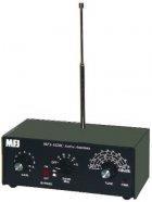
23 Diversity cont d I wanted to have diversity capability at VE7KW and thought that an active antenna could provide this. The mini-whip fascinated me because of its simplicity and small size <0.5m. I built this antenna and felt that it did not have the required sensitivity so decided that I could improve upon the design. 23
24 Improved? Active Vertical Dipole I noted that the University of Twente appear to have gone to a vertical dipole configuration and moved the Antenna to the roof and clear of local noise sources. Increase the size/capacitance by using longer and larger diameter elements to increase signal I thought that going to a current mode integrated circuit amplifier could provide the low capacitance, differential, broad bandwidth, high common mode amplifier desired Use CAT5e or CAT6 shielded cable for the transmission line Isolate power supply 24
25 use the K3 dynamic range of 106 db say 100 db. minimum input voltage 0.1uV. Maximum signal = 1V. A dipole element 3cm by 10cm each side will be 30 pf. The input capacitance is 3 pf so we only lose 0.9 db due to the capacitor signal division. -100dBm is -24 dbuv/m = V/m. The antenna is 0.66m long so input voltage is 0.04 uv. Thus a preamp gain of 10 db is required. The equivalent input noise for the LM1385 is 3.2nV/sqrtHz. So for 500 Hz = 0.7 uv 25
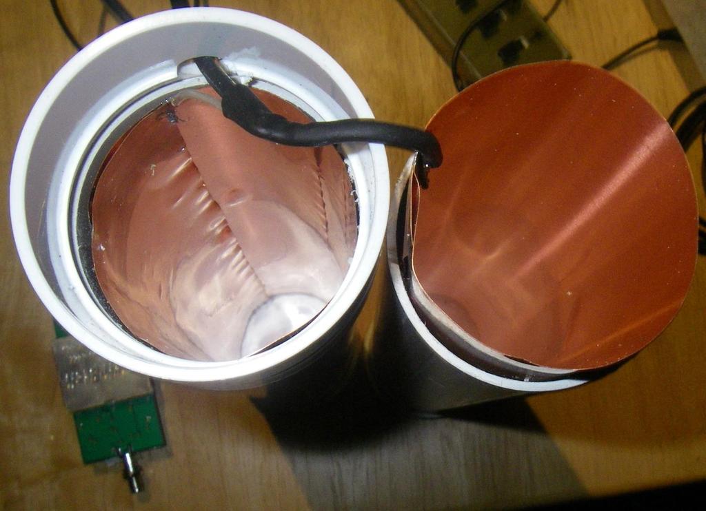
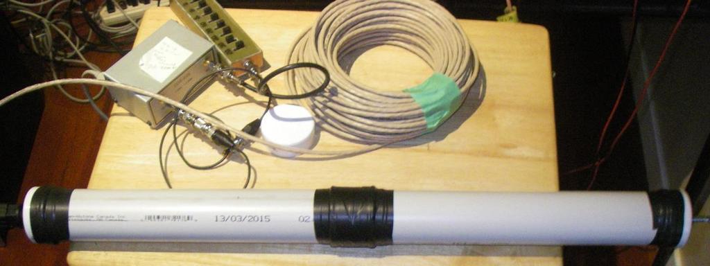
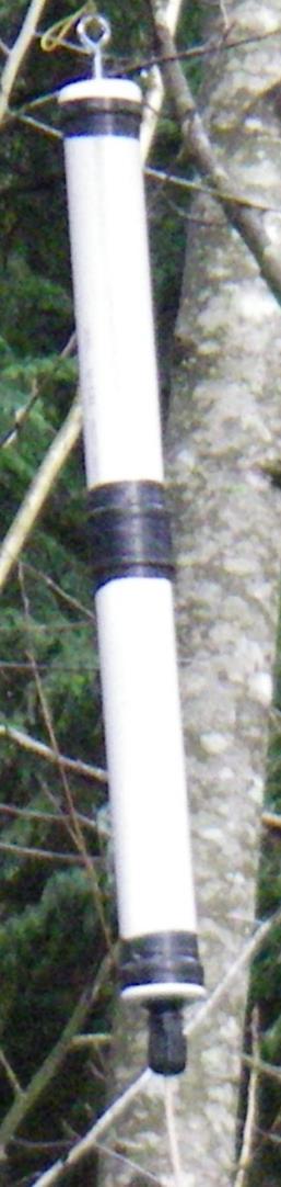
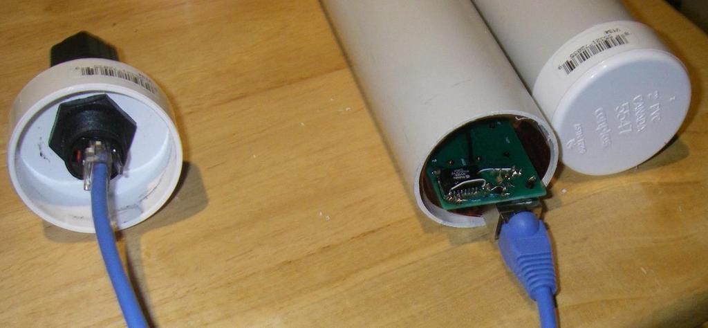
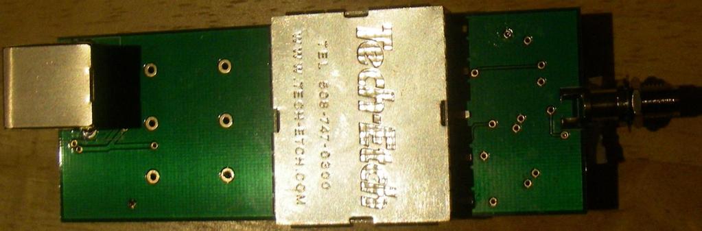
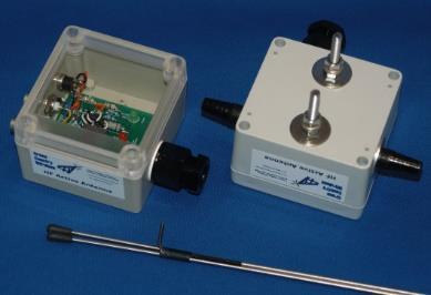
26 Antenna Design Copper sheet is rolled into 2in Dia PVC tube configured as an ~ 1m dipole. The amplifier board is inside the copper sheet which acts as a shield The Cat5 is connected through a shielded waterproof connector via a short jumper. Low cost Cat5 CAT cable is used. CAT6 is now available. Hung in the trees at about 5m high 26
27 27
28 28


29 This is interesting, a low horizontal dipole is effectively isotropic and does not show low elevation lobes until > 1/4λabove ground. Figure 180m Horizontal dipole at 1m Figure 2 80m Horizontal Dipole at 40m A low vertical dipole starts off with low lobes and become more isotropic as it is raised. 29


30 Considering that I was likely to end up at 6m, these models caused me to change my mind about needing a vertical dipole. Figure 3 80m vertical dipole at 1m Figure 4z80m Vertical dipole at 40m A low vertical dipole starts off with low lobes and become more isotropic as it is raised. 30
31 Amplifier I went through a number of amplifier designs using various IC amplifiers. What I ended up with was Fet front end to act as an impedance transformer to give low capacitance, high impedance to the antenna and differential current to the Current Feedback video amplifier. Current feedback amplifer for high gain bandwidth Line driver amplifier for the CAT5 +/- 5V isolated switching supply CAT5 isolation transformers 31


32 40dB gain referenced to one input and flat to beyond 100 MHz. 32
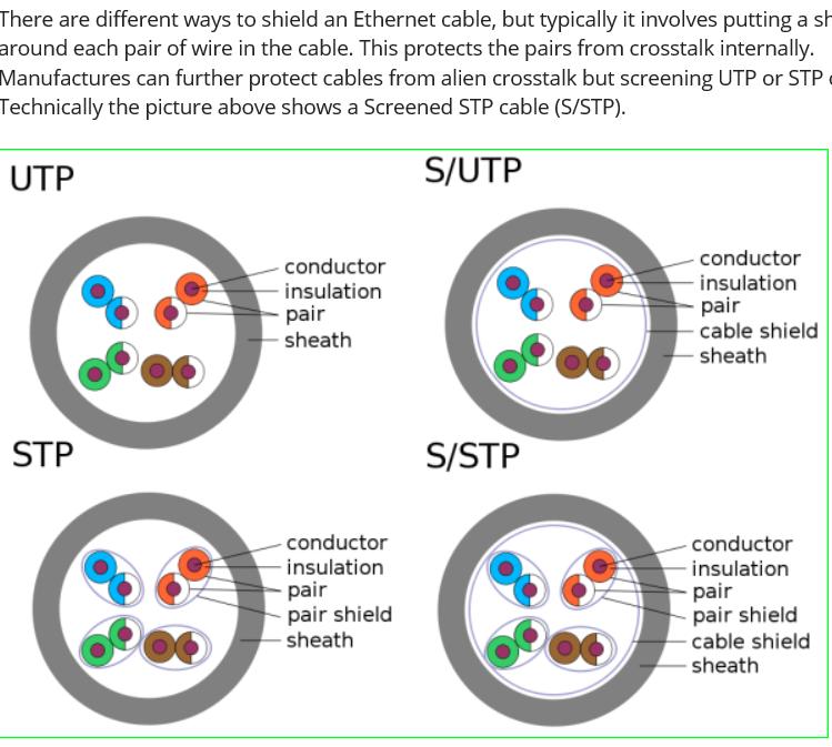
33 Cat 5 transmission line Well known to be effective for noise reduction simplifies transmission of amplifier DC power Can be transformer isolated Nominal 110 ohm (can be configured for 50 ohm) Can have additional shielding Standard connectors; shielding and sealed more of a problem Low cost (even Cat6 now) 33
34 Cat 5 Transmission line cont d This became a major project I had a supply of CAT transmission line transformers but had a steep learning curve on their use Compensation for wide band Use with DC power Driving and receiving Decided ultimately that the transformers were probably not needed 34
35 35
36 Cat 5 Transmission line cont d When I started CAT6 (individually shielded with outer shield) was very rare and expensive. Now it is being used all over for new installations. I had some waterproof connectors and could find shielded connectors. Again this is much easier now. Bandwidth and matching was not a problem 36
37 37

38 Cat 5 Transmission line cont d 38
39 Amplifier Power Supply I was concerned about noise pickup. In addition, it appeared as if a +/- supply would be required. I thought that I had an easy solution where I would send up 12VDC and use a local isolated power supply. This became a major issue with separate shields and extensive choke/capacitor isolation required. 39

40 40

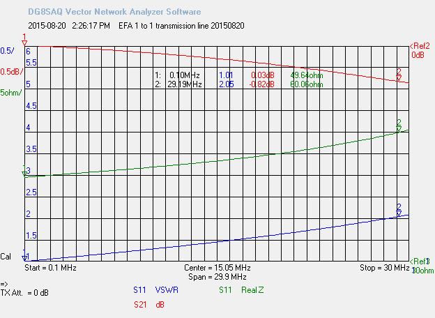
41 This shows my improved EFA1 antenna to the Miniwhip MW1 from 1 to 30 MHz 41
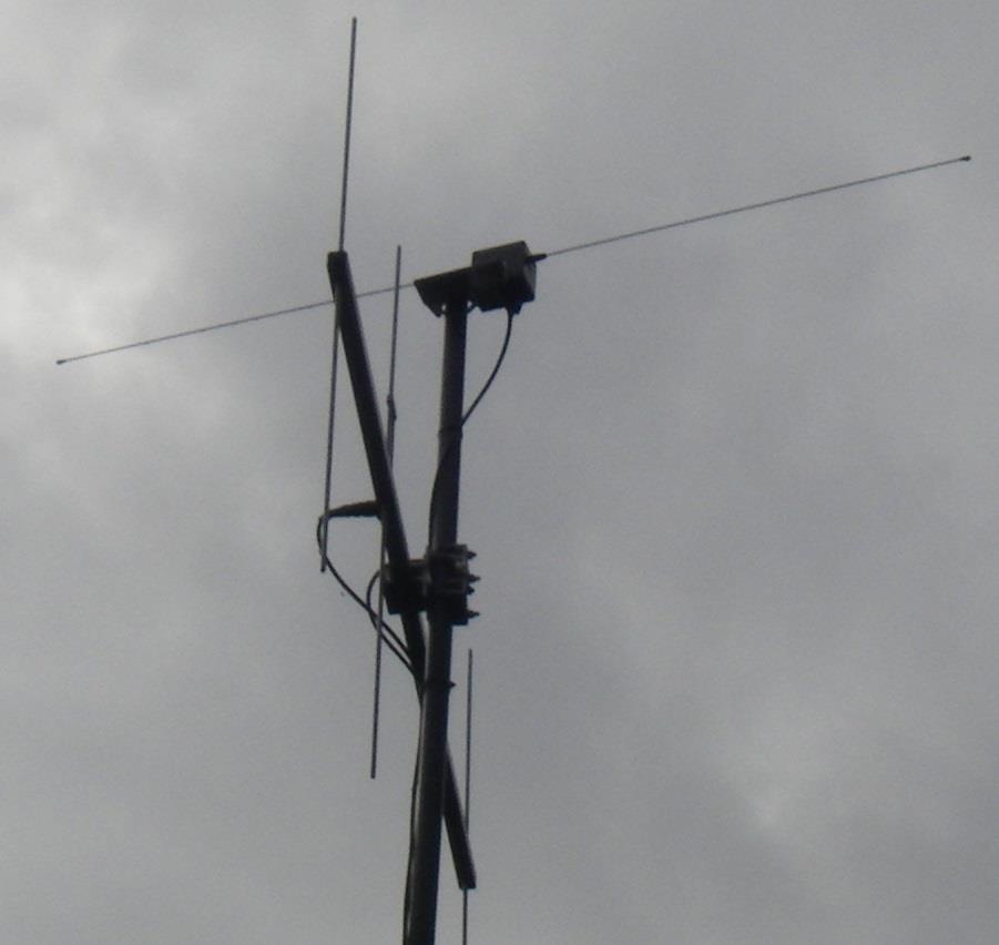
42 At this point I decided that I needed a Benchmark and ordered a Cross-Country Wireless Active antenna. This is a 1m dipole with a conventional 2N5109 amplifier and CAT5 transmission line. I found that this had similar performance in the trees as my active antennas. It improved when placed on the mast holding my VHF beam to where it equaled or exceeded the R9. Note the R9 is a multiband resonant vertical. It is down in comparison to my 160/80/60m dipole at 50 ft but works down to 60kHz. 42
43 43
44 44
45 db Active Antennas 45 s/n X-Country at 30 Ft s/n against WWV X Country R MHz 45
46 Conclusions Active antennas work BUT: They have to be away from any noise sources (house wiring), buildings or trees They have to be decoupled from their transmission lines They are not noise cancelling. They can make a poor receiver better and in high noise locations can offer a s/n improvement. Active Antennas are an attractive choice for broadband SDR receiver applications The SDR will have to be able to handle any strong signals in the antenna bandwidth 46
47 Conclusions cont d The amplifiers are non-trivial The traditional 2N5109 designs work well High gain bandwidth/low noise figure/high 3IP devices CAT5/6 can work and is a good choice for transmission lines The improved EFA has potential but, at this time, is on hold as the improvement would be small. 47
48 Here, as stated by W8JI, is the bottom line stated for larger loops but applicable in general At -140 dbm and 250 Hz noise bandwidth, the system would require a 1 db noise figure front end. The only place negative gain antennas that require more than ~ 20 db gain with a normal receiver at a quiet location will work into the external ambient noise floor generated outside the antenna is in a location blanketed with strong local noise. Besides that, if the gain is so far negative the coaxial cable will easily become more of an antenna than the thing we call an antenna So, if you already have a decent receiver, antenna and location, there is no improvement to be had. 48
49 The EFA projects gave me an opportunity to drag my self into the 21 st century world of modelling, (EZNEC, LTSpice), layout software (CircuitMaker) and using modern surface mount components; ICs (CFA, Isolated switching modules), transformers. Next day delivery is a true wonder! I would like to thank Nick Massey VA7NRM for assistance with the modelling and circuit layout. Dave Miller VE7HR facilitated my prototypes and encouraged me through the dark times with CircuitMaker. 49
Magnetic Loop Antenna - Topbands
 Magnetic Loop Antenna - Topbands Instruction Manual Thank you for purchasing this new product small Magnetic Loop Antenna Topbands. Manual contains important information. Please read all instructions carefully
Development of a noval Switched Beam Antenna for Communications
 Master Thesis Presentation Development of a noval Switched Beam Antenna for Communications By Ashraf Abuelhaija Supervised by Prof. Dr.-Ing. Klaus Solbach Institute of Microwave and RF Technology Department
A Compact Active Wide-Band Receiving Antenna [Part 1] Report by Derek G3GRO
![A Compact Active Wide-Band Receiving Antenna [Part 1] Report by Derek G3GRO](/thumbs/88/115261937.jpg "A Compact Active Wide-Band Receiving Antenna [Part 1] Report by Derek G3GRO") efficiency and assessing your abilities as an operator. You don t have to be up there among the high scoring big-guns to have some fun, but if your are a regular contender in a particular annual contest
efficiency and assessing your abilities as an operator. You don t have to be up there among the high scoring big-guns to have some fun, but if your are a regular contender in a particular annual contest
Chapter 6 Antenna Basics. Dipoles, Ground-planes, and Wires Directional Antennas Feed Lines
 Chapter 6 Antenna Basics Dipoles, Ground-planes, and Wires Directional Antennas Feed Lines Some General Rules Bigger is better. (Most of the time) Higher is better. (Most of the time) Lower SWR is better.
VHF/UHF Dual Band J-Pole. By: Ed Fong WB6IQN
 VHF/UHF Dual Band J-Pole By: Ed Fong WB6IQN email: edison_fong@hotmail.com ARRL VHF/UHF Antenna Classics ARRL Vol. 8 Antenna Compendium ARRL Vol. 3 Antenna Compendium QST March 2007 QST February 2003 QST
HF Receivers, Part 2
 HF Receivers, Part 2 Superhet building blocks: AM, SSB/CW, FM receivers Adam Farson VA7OJ View an excellent tutorial on receivers NSARC HF Operators HF Receivers 2 1 The RF Amplifier (Preamp)! Typical
6 Radio and RF. 6.1 Introduction. Wavelength (m) Frequency (Hz) Unit 6: RF and Antennas 1. Radio waves. X-rays. Microwaves. Light
 Frequency (Hz) Unit 6: RF and Antennas 1. Radio waves. X-rays. Microwaves. Light") 6 Radio and RF Ref: http://www.asecuritysite.com/wireless/wireless06 6.1 Introduction The electromagnetic (EM) spectrum contains a wide range of electromagnetic waves, from radio waves up to X-rays (as
6 Radio and RF Ref: http://www.asecuritysite.com/wireless/wireless06 6.1 Introduction The electromagnetic (EM) spectrum contains a wide range of electromagnetic waves, from radio waves up to X-rays (as
G6ALU 20W FET PA Construction Information
 G6ALU 20W FET PA Construction Information The requirement This amplifier was designed specifically to complement the Pic-A-Star transceiver developed by Peter Rhodes G3XJP. From the band pass filter an
Technician Licensing Class T9
 Technician Licensing Class T9 Amateur Radio Course Monroe EMS Building Monroe, Utah January 11/18, 2014 January 22, 2014 Testing Session Valid dates: July 1, 2010 June 30, 2014 Amateur Radio Technician
Low Band Receiving Antennas
 Low Band Receiving Antennas (on a city lot) Ned Stearns, AA7A How do you know you need a Receive Antenna? Scenario #1 Many DX stations hear you much better than you hear them Scenario #2 When your DXerneighbor
Antenna Design for FM-02
 Antenna Design for FM-02 I recently received my FM-02 FM transmitter which I purchased from WLC. I researched the forum on what antennas where being used by the DIY community and found a nice write-up
Array Solutions. Model AS-AYL-4 4-way K9AY Loop System
 Array Solutions Model AS-AYL-4 4-way K9AY Loop System This is the popular K9AY Loop receiving antenna, as described in the September 1997 issue of QST, The K9AY Terminated Loop-A Compact, Directional Receiving
4/25/2012. Supplement T9. 2 Exam Questions, 2 Groups. Amateur Radio Technician Class T9A: T9A: T9A: T9A:
 Amateur Radio Technician Class Element 2 Course Presentation ti ELEMENT 2 SUB-ELEMENTS Technician Licensing Class Supplement T9 Antennas, Feedlines 2 Exam Questions, 2 Groups T1 - FCC Rules, descriptions
Magnetic Loop Antenna - Top Bands
 Magnetic Loop Antenna - Top Bands Instruction Manual Thank you for purchasing this new product small Magnetic Loop Antenna Top Bands. Manual contains important information. Please read all instructions
CHAPTER 8 ANTENNAS 1
 CHAPTER 8 ANTENNAS 1 2 Antennas A good antenna works A bad antenna is a waste of time & money Antenna systems can be very inexpensive and simple They can also be very expensive 3 Antenna Considerations
14 MHz Single Side Band Receiver
 EPFL - LEG Laboratoires à options 8 ème semestre MHz Single Side Band Receiver. Objectives. The objective of this work is to calculate and adjust the key elements of an Upper Side Band Receiver in the
Technician Licensing Class. Antennas
 Technician Licensing Class Antennas Antennas A simple dipole mounted so the conductor is parallel to the Earth's surface is a horizontally polarized antenna. T9A3 Polarization is referenced to the Earth
87415A microwave system amplifier A microwave. system amplifier A microwave system amplifier A microwave.
 20 Amplifiers 83020A microwave 875A microwave 8308A microwave 8307A microwave 83006A microwave 8705C preamplifier 8705B preamplifier 83050/5A microwave The Agilent 83006/07/08/020/050/05A test s offer
Small Magnetic Loops: A Beginner s Guide WOW! This is a very different antenna!
 Small Magnetic Loops: A Beginner s Guide WOW! This is a very different antenna! Dave Wickert, AE7TD Lake Washington Ham Club November 2018 Meeting 10-Nov-2018 Dayton Hamvention 2017 History Full Size Loops
COAXIAL TRANSMISSION LINE COMMON-MODE CURRENT
 COAXIAL TRANSMISSION LINE COMMON-MODE CURRENT Introduction Coaxial transmission lines are popular for their wide frequency bandwidth and high resistance to electromagnetic interference (EMI). Coax cables
Array Solutions 350 Gloria Rd Sunnyvale, TX USA PHN FAX
 Array Solutions 350 Gloria Rd Sunnyvale, TX 75182 USA PHN 972 203 2008 FAX 972 203 8811 E-MAIL sales@arraysolutions.com Model AS-AYL-4 4-way K9AY Loop System This is the popular K9AY Loop receiving antenna,
Trees, vegetation, buildings etc.
 EMC Measurements Test Site Locations Open Area (Field) Test Site Obstruction Free Trees, vegetation, buildings etc. Chamber or Screened Room Smaller Equipments Attenuate external fields (about 100dB) External
Antennas Demystified Antennas in Emergency Communications. Scott Honaker N7SS
 Antennas Demystified Antennas in Emergency Communications Scott Honaker N7SS Importance of Antennas Antennas are more important than the radio A $5000 TV with rabbit ears will have a lousy picture Antennas
Technician License. Course
 Technician License Course Technician License Course Chapter 4 Lesson Plan Module - 10 Practical Antennas The Dipole Most basic antenna The Dipole Most basic antenna The Dipole Total length is ½ wavelength
HF LNA Doug Ronald W6DSR HF LNA
 HF LNA 1 High Dynamic Range 1.5 30 MHz Low Noise Amplifier. By Doug Ronald, W6DSR I have always had an interest in building high-performance receivers and transmitters for HF. An expected performance metric
Television and video engineering
 Television and video engineering Unit-4 Television Receiver systems Objectives: To learn the requirements of TV receiver Study of monochrome and Colour TV receivers. To learn functions of Tuning circuits
4/29/2012. General Class Element 3 Course Presentation. Ant Antennas as. Subelement G9. 4 Exam Questions, 4 Groups
 General Class Element 3 Course Presentation ti ELEMENT 3 SUB ELEMENTS General Licensing Class Subelement G9 Antennas and Feedlines 4 Exam Questions, 4 Groups G1 Commission s Rules G2 Operating Procedures
MAHALAKSHMI ENGINEERING COLLEGE TIRUCHIRAPALLI UNIT III TUNED AMPLIFIERS PART A (2 Marks)
") MAHALAKSHMI ENGINEERING COLLEGE TIRUCHIRAPALLI-621213. UNIT III TUNED AMPLIFIERS PART A (2 Marks) 1. What is meant by tuned amplifiers? Tuned amplifiers are amplifiers that are designed to reject a certain
MAHALAKSHMI ENGINEERING COLLEGE TIRUCHIRAPALLI-621213. UNIT III TUNED AMPLIFIERS PART A (2 Marks) 1. What is meant by tuned amplifiers? Tuned amplifiers are amplifiers that are designed to reject a certain
SPECTRACOM MODEL 8165 DISCIPLINED OSCILLATOR ANTENNA INSTALLATION TABLE OF CONTENTS
 SPECTRACOM MODEL 8165 DISCIPLINED OSCILLATOR ANTENNA INSTALLATION TABLE OF CONTENTS Page 1.0 INTRODUCTION... 1 1.3 MODEL 8206A LOOP ANTENNA... 1 1.4 MODEL 8208 WHIP ANTENNA... 4 1.5 ANTENNA LOCATION...
Technician License Course Chapter 4. Lesson Plan Module 9 Antenna Fundamentals, Feed Lines & SWR
 Technician License Course Chapter 4 Lesson Plan Module 9 Antenna Fundamentals, Feed Lines & SWR The Antenna System Antenna: Transforms current into radio waves (transmit) and vice versa (receive). Feed
Easy to Build Low Band Receiving Antennas for Small and Large Lots
 Easy to Build Low Band Receiving Antennas for Small and Large Lots Small antennas High performance antennas Quantitative performance evaluation Frank Donovan W3LPL Why Receiving Antennas? Much better performance
RF PRO-1B INSTALLATION INSTRUCTIONS
 P ixel TECHNOLOGIES RF PRO-1B INSTALLATION INSTRUCTIONS This active magnetic loop antenna is designed for reception of signals over the range of 50 khz to 30 MHz. It includes a very high dynamic range
PCB Antenna with Cable Integration Application Note Version 4
 PCB Antenna with Cable Integration Application Note Version 4 CONTENTS 1. BASICS 2. APPLICATIONS 3. SIZE 4. SHAPE 5. GROUND PLANE SIZE 6. IMPEDANCE 7. BANDWIDTH 8. VSWR 9. GAIN 10. EFFICIENCY 11. POLARIZATION
Loop Antennas for HF Reception
 COMMUNICATIONS 74 CONFERENCE BRIGHTON Wednesday, June 5 1974 Session 5, Equipment Design Paper 5.3: Loop Antennas for HF Reception Contributed by: B.S.Collins, C & S Antennas Ltd., Knight Road, Rochester,
Milton Keynes Amateur Radio Society (MKARS)
") Milton Keynes Amateur Radio Society (MKARS) Intermediate Licence Course Feeders Antennas Matching (Worksheets 31, 32 & 33) MKARS Intermediate Licence Course - Worksheet 31 32 33 Antennas Feeders Matching
Milton Keynes Amateur Radio Society (MKARS) Intermediate Licence Course Feeders Antennas Matching (Worksheets 31, 32 & 33) MKARS Intermediate Licence Course - Worksheet 31 32 33 Antennas Feeders Matching
Chapter 12: Transmission Lines. EET-223: RF Communication Circuits Walter Lara
 Chapter 12: Transmission Lines EET-223: RF Communication Circuits Walter Lara Introduction A transmission line can be defined as the conductive connections between system elements that carry signal power.
ANTENNAS. I will mostly be talking about transmission. Keep in mind though, whatever is said about transmission is true of reception.
 Reading 37 Ron Bertrand VK2DQ http://www.radioelectronicschool.com ANTENNAS The purpose of an antenna is to receive and/or transmit electromagnetic radiation. When the antenna is not connected directly
ANTENNA BASICS FOR BEGINNERS
 ANTENNA BASICS FOR BEGINNERS PART 2 -DIPOLES DIPOLES -General MULTIBAND DIPOLES RF CHOKES 1 DIPOLES Several different variations of the dipole are also used, such as the folded dipole, short dipole, cage
Varactor-Tuned Oscillators. Technical Data. VTO-8000 Series
 Varactor-Tuned Oscillators Technical Data VTO-8000 Series Features 600 MHz to 10.5 GHz Coverage Fast Tuning +7 to +13 dbm Output Power ± 1.5 db Output Flatness Hermetic Thin-film Construction Description
CHAPTER - 6 PIN DIODE CONTROL CIRCUITS FOR WIRELESS COMMUNICATIONS SYSTEMS
 CHAPTER - 6 PIN DIODE CONTROL CIRCUITS FOR WIRELESS COMMUNICATIONS SYSTEMS 2 NOTES 3 INTRODUCTION PIN DIODE CONTROL CIRCUITS FOR WIRELESS COMMUNICATIONS SYSTEMS Chapter 6 discusses PIN Control Circuits
FCC Technician License Course
 FCC Technician License Course 2014-2018 FCC Element 2 Technician Class Question Pool Presented by: Tamiami Amateur Radio Club (TARC) WELCOME To the third of 4, 3-hour classes presented by TARC to prepare
Colubris Networks. Antenna Guide
 Colubris Networks Antenna Guide Creation Date: February 10, 2006 Revision: 1.0 Table of Contents 1. INTRODUCTION... 3 2. ANTENNA TYPES... 3 2.1. OMNI-DIRECTIONAL ANTENNA... 3 2.2. DIRECTIONAL ANTENNA...
CONNECTING THE PROBE TO THE TEST INSTRUMENT
 2SHUDWLRQ 2SHUDWLRQ Caution The input circuits in the AP034 Active Differential Probe incorporate components that protect the probe from damage resulting from electrostatic discharge (ESD). Keep in mind
SCHWARZBECK MESS - ELEKTRONIK An der Klinge 29 D Schönau Tel.: 06228/1001 Fax.: (49)6228/1003
6228/1003") Calibration of Vertical Monopole Antennas (9kHz - 30MHz) 11112gs VAMPINFO 1. Introduction Vertical Monopole Antennas are used for the measurement of the electric component of EM fields, especially in the
Calibration of Vertical Monopole Antennas (9kHz - 30MHz) 11112gs VAMPINFO 1. Introduction Vertical Monopole Antennas are used for the measurement of the electric component of EM fields, especially in the
Radio Receivers. Al Penney VO1NO
 Radio Receivers Al Penney VO1NO Role of the Receiver The Antenna must capture the radio wave. The desired frequency must be selected from all the EM waves captured by the antenna. The selected signal is
High Dynamic Range Receiver Parameters
 High Dynamic Range Receiver Parameters The concept of a high-dynamic-range receiver implies more than an ability to detect, with low distortion, desired signals differing, in amplitude by as much as 90
Methods for Reducing Emissions from Switching Power Circuits. A. McDowell, C. Zhu and T. Hubing
 Methods for Reducing Emissions from Switching Power Circuits A. McDowell, C. Zhu and T. Hubing 1 Objective To reduce radiated emissions and other forms of interference from power inverter circuits, by
Basic Wire Antennas. Part II: Loops and Verticals
 Basic Wire Antennas Part II: Loops and Verticals A loop antenna is composed of a single loop of wire, greater than a half wavelength long. The loop does not have to be any particular shape. RF power can
Radio Receivers. Al Penney VO1NO
 Radio Receivers Role of the Receiver The Antenna must capture the radio wave. The desired frequency must be selected from all the EM waves captured by the antenna. The selected signal is usually very weak
Technician License. Course
 Technician License Course Technician License Course Chapter 4 Lesson Plan Module - 9 Antenna Fundamentals Feed Lines & SWR The Antenna System The Antenna System Antenna: Transforms current into radio waves
Principles of Multicoupler Design 2009
 Multicouplers General A multicoupler is a device which connects a signal source to multiple units. The most common arrangement is for splitting a single antenna so that it can feed a number of receivers.
A 3-Stage Shunt-Feedback Op-Amp having 19.2dB Gain, 54.1dBm OIP3 (2GHz), and 252 OIP3/P DC Ratio
, and 252 OIP3/P DC Ratio") International Microwave Symposium 2011 Chart 1 A 3-Stage Shunt-Feedback Op-Amp having 19.2dB Gain, 54.1dBm OIP3 (2GHz), and 252 OIP3/P DC Ratio Zach Griffith, M. Urteaga, R. Pierson, P. Rowell, M. Rodwell,
International Microwave Symposium 2011 Chart 1 A 3-Stage Shunt-Feedback Op-Amp having 19.2dB Gain, 54.1dBm OIP3 (2GHz), and 252 OIP3/P DC Ratio Zach Griffith, M. Urteaga, R. Pierson, P. Rowell, M. Rodwell,
M2 Antenna Systems, Inc. Model No: 2M HO LOOP
 M2 Antenna Systems, Inc. Model No: 2M HO LOOP SPECIFICATIONS: Model... 2M HO LOOP Frequency Range... 144 To 144.5 MHz Gain, Typical @ 10 ft.... 4 dbd @ 10 deg. Gain, 2 STK @ 82 & 132... 8 dbd @ 9 deg.
Three Loop Antenna Array with Electrically-Rotatable Nulling Mark Connelly, WA1ION - 5 OCT 2000
 Three Loop Antenna Array with Electrically-Rotatable Nulling Mark Connelly, WA1ION - 5 OCT 2000 By using three broadband loop antennas set up at 120 degree bearing differences, a fully rotatable single-null
Ameritron RCS-10 INTRODUCTION
 Ameritron RCS-10 INTRODUCTION The RCS-10 is a versatile antenna switch designed for 50-ohm systems. It handles high power, and sealed relays offer excellent life and connection reliability. It requires
4. Questions and Answers
 Contents: 4.1 Amplifier 4.1 4.2 Antenna 4.7 4.3 Cable 4.11 4.4 Links 4.12 4. Questions and Answers 4.1 Amplifier 1. What are the requirements for the DC power supply (PS) voltage? Measured minimal voltage
Ground-Mounted Verticals. Dispelling the Myths and Misconceptions
 Dispelling the Myths and Misconceptions Let s start with a quiz on vertical antennas and radials. Answers will be there to discover, as we proceed through the presentation. To be most effective, a ground-mounted
IC-R8500 Test Report. By Adam Farson VA7OJ/AB4OJ
 IC-R8500 Test Report By Adam Farson VA7OJ/AB4OJ Iss. 1, Dec. 14, 2015. Figure 1: The Icom IC-R8500. Introduction: This report presents results of an RF lab test suite performed on the IC- R8500 receiver.
A short, off-center fed dipole for 40 m and 20 m by Daniel Marks, KW4TI
 A short, off-center fed dipole for 40 m and 20 m by Daniel Marks, KW4TI Version 2017-Nov-7 Abstract: This antenna is a 20 to 25 foot long (6.0 m to 7.6 m) off-center fed dipole antenna for the 20 m and
UNIT Write short notes on travelling wave antenna? Ans: Travelling Wave Antenna
 UNIT 4 1. Write short notes on travelling wave antenna? Travelling Wave Antenna Travelling wave or non-resonant or aperiodic antennas are those antennas in which there is no reflected wave i.e., standing
Optimizing Your Stations Performance
 Optimizing Your Stations Performance A few hints / techniques, recommendations for getting the most RF out to the Antenna from your HF, VHF / UHF station. Tonights Presenters: Doug Theriault NO1D John
1 Introduction. Webinar sponsored by: Cost-effective uses of close-field probing. Contents
 1of 8 Close-field probing series Webinar #1 of 2, Cost-effective uses of close-field probing in every project stage: emissions, immunity and much more Webinar sponsored by: Keith Armstrong CEng, EurIng,
Antennas and Propagation Chapters T4, G7, G8 Antenna Fundamentals, More Antenna Types, Feed lines and Measurements, Propagation
 Antennas and Propagation Chapters T4, G7, G8 Antenna Fundamentals, More Antenna Types, Feed lines and Measurements, Propagation =============================================================== Antenna Fundamentals
DIY 137 MHz APT Weather satellite antenna Or, do we need a circular polarization?
 DIY 137 MHz APT Weather satellite antenna Or, do we need a circular polarization? What we are listening At the moment there are three NOAA satellites available transmitting the APT weather pictures in
Differential Amplifiers
 Differential Amplifiers Benefits of Differential Signal Processing The Benefits Become Apparent when Trying to get the Most Speed and/or Resolution out of a Design Avoid Grounding/Return Noise Problems
Install as much wire/tubing as possible Electrically short antennas Minimize matching losses Good ground for verticals Maximizes antenna efficiency
 Jim Wolf KR9U Install as much wire/tubing as possible Electrically short antennas Minimize matching losses Good ground for verticals Maximizes antenna efficiency Far-away ground conditions determine low
Coaxial Cable Protection
 Coaxial Cable Protection 1485-005 Technical Note Coaxial Cable Protection Coaxial Cable Protection Why is coaxial cable protection needed? Skin effect is a physical phenomenon that relates to the limited
Application Note Receivers MLX71120/21 With LNA1-SAW-LNA2 configuration
 Designing with MLX71120 and MLX71121 receivers using a SAW filter between LNA1 and LNA2 Scope Many receiver applications, especially those for automotive keyless entry systems require good sensitivity
Definitions of Technical Terms
 Definitions of Technical Terms Terms Ammeter Amperes, Amps Band Capacitor Carrier Squelch Diode Dipole Definitions How is an ammeter usually connected = In series with the circuit What instrument is used
Technician Licensing Class. Lesson 4. presented by the Arlington Radio Public Service Club Arlington County, Virginia
 Technician Licensing Class Lesson 4 presented by the Arlington Radio Public Service Club Arlington County, Virginia 1 Quiz Sub elements T6 & T7 2 Good Engineering Practice Sub element T8 3 A Basic Station
200 ma Output Current High-Speed Amplifier AD8010
 a FEATURES 2 ma of Output Current 9 Load SFDR 54 dbc @ MHz Differential Gain Error.4%, f = 4.43 MHz Differential Phase Error.6, f = 4.43 MHz Maintains Video Specifications Driving Eight Parallel 75 Loads.2%
VLF-LF-MF Up Converter
 VLF-LF-MF Up Converter 5kHz-500kHz 3.5MHz-4MHz model 350 4MHz-4.5MHz model 400 User manual. Rev 2018-01 Since many countries are allocating the 472 khz to 479kHZ band for experimental use by Radio Amateurs,
Chokes and Isolation Transformers For Receiving Antennas By Jim Brown K9YC 2018 by James W. Brown All rights reserved
 Chokes and Isolation Transformers For Receiving Antennas By Jim Brown K9YC 2018 by James W. Brown All rights reserved Why We Need Them A feedline must be grounded where it enters the shack-for lightning
Table of Contents. MFJ-1778 G5RV Multiband Antenna
 Table of Contents MFJ-1778 G5RV Multiband Antenna Introduction... 1 Theory Of Operation... 1 80 meter band:... 1 40 meter band:... 1 30 meter band:... 2 20 meter band:... 2 17 meter band:... 2 15 meter
EFFECT OF SHIELDING ON CABLE RF INGRESS MEASUREMENTS LARRY COHEN
 EFFECT OF SHIELDING ON CABLE RF INGRESS MEASUREMENTS LARRY COHEN OVERVIEW Purpose: Examine the common-mode and differential RF ingress levels of 4-pair UTP, F/UTP, and F/FTP cables at an (RJ45) MDI port
An Introduction to Radio Frequency Interference
 An Introduction to Radio Frequency Interference Ron Hranac, N0IVN Member, ARRL EMC Committee ARRL Colorado Section Technical Specialist What is RFI? RFI is an abbreviation for radio frequency interference
VE7CNF - 630m Antenna Matching Measurements Using an Oscilloscope
 VE7CNF - 630m Antenna Matching Measurements Using an Oscilloscope Toby Haynes October, 2016 1 Contents VE7CNF - 630m Antenna Matching Measurements Using an Oscilloscope... 1 Introduction... 1 References...
Module 8 Theory. dbs AM Detector Ring Modulator Receiver Chain. Functional Blocks Parameters. IRTS Region 4
 Module 8 Theory dbs AM Detector Ring Modulator Receiver Chain Functional Blocks Parameters Decibel (db) The term db or decibel is a relative unit of measurement used frequently in electronic communications
Demo Circuit DC550A Quick Start Guide.
 May 12, 2004 Demo Circuit DC550A. Introduction Demo circuit DC550A demonstrates operation of the LT5514 IC, a DC-850MHz bandwidth open loop transconductance amplifier with high impedance open collector
NEAR FIELD MEASURING MEASURING SET-UP. LANGER E M V - T e c h n i k
 MEASURING SET-UP NEAR FIELD MEASURING The measurement of near fields to 6 GHz directly on electronic modules aids in the reduction of disturbance emission. Near field probes measurement setup-0513pe 2
1.5 kw Automatic Remote Controlled Antenna Tuner for Verticals and other Unbalanced Antennas
 1.5 kw Automatic Remote Controlled Antenna Tuner for Verticals and other Unbalanced Antennas Mod. AT- 615U Short Form Manual 10/2010 Dipl.Ing. Klaus Bemmerer RF Communication Electronics Niendorf-Middeldor
My experience with the ANC-4 on 50 MHz Rev. 1
 My experience with the ANC-4 on 50 MHz Rev. 1 by Antonio Vernucci, I0JX 1. General The ANC-4 (Antenna Noise Canceller - 4) is intended to reduce the impairment of weak DX signals reception caused by local
The DBJ-1: A VHF-UHF Dual-Band J-Pole
 By Edison Fong, WB6IQN The DBJ-1: A VHF-UHF Dual-Band J-Pole Searching for an inexpensive, high-performance dual-band base antenna for VHF and UHF? Build a simple antenna that uses a single feed line for
The pa0rdt-mini-whip, an active receiving antenna for 10 khz to 20 MHz
 The pa0rdt-mini-whip, an active receiving antenna for 10 khz to 20 MHz by Roelof Bakker PA0RDT "The article was published in the May 2006 issue of Electron, the magazine of the VERON, the Dutch main amateur
Dressler ARA-2000 active antenna what s inside?
 Dressler ARA-2000 active antenna what s inside? Matthias Bopp Updated October 23 rd 2011 Dressler active antennas have an excellent reputation and thus I was interested how they are comprised before buying
Rx antennas at IV3PRK: the 4-Square Rx Vertical Array
 Rx antennas at IV3PRK: the 4-Square Rx Vertical Array Part 2: putting all stuff together and construction details Calculating the cable lengths by Pierluigi Luis Mansutti IV3PRK The most difficult choice,
PA3GZK's WIDE BAND ACTIVE LOOP RECEIVING ANTENNA
 PA3GZK's WIDE BAND ACTIVE LOOP RECEIVING ANTENNA 03-jan-2018 WebSDR Weert (NL) use this active loop antenna. 7 Left my green coloured loop as distinctive "bush" in my garden and on the right in PA3GZK's
Title: New High Efficiency Intermodulation Cancellation Technique for Single Stage Amplifiers.
 Title: New High Efficiency Intermodulation Cancellation Technique for Single Stage Amplifiers. By: Ray Gutierrez Micronda LLC email: ray@micronda.com February 12, 2008. Introduction: This article provides
VLF-LF Up Converter 5KHz - 500KHz. User manual. Rev HEROS technology Limited All rights reserved
 VLF-LF Up Converter 5KHz - 500KHz User manual. Rev 2016-02 Since many countries are allocating the 472 khz to 479kHZ band for experimental use by Radio Amateurs, a growing number of them as well as listeners
Beams and Directional Antennas
 Beams and Directional Antennas The Horizontal Dipole Our discussion in this chapter is about the more conventional horizontal dipole and the simplified theory behind dipole based designs. For clarity,
Amateur Radio License. Propagation and Antennas
 Amateur Radio License Propagation and Antennas Todays Topics Propagation Antennas Propagation Modes Ground wave Low HF and below, ground acts as waveguide Line-of-Sight (LOS) VHF and above, radio waves
WCARC Beacon Project. Update 2 June, Doug Leach VE3XK
 Update 2 June, 2008 Doug Leach VE3XK Status Report Enclosure complete - houses up to six beacon modules 70CM module has been running flawlessly for 8 wks into 70CM KU4AB omni antenna mounted on a PVC conduit
Cray Valley Radio Society. Real Life Wire Antennas
 Cray Valley Radio Society Real Life Wire Antennas 1 The basic dipole The size of an antenna is determined by the wavelength of operation In free space: ~3x10 8 m/s Frequency x Wavelength = Speed of Light,
HF Wire Antennas, EMI Contest Stations. WCARC November 2016 VE3KL
 HF Wire Antennas, EMI Contest Stations WCARC November 2016 VE3KL Introduction A Top Down View of a Radio Station(s) 1. Wire Antenna Design...Ideas needed.. 2. Dipoles and Unwanted Radiation (EMI) 3. A
Specification for Radiated susceptibility Test
 1 of 11 General Information on Radiated susceptibility test Supported frequency Range : 20MHz to 6GHz Supported Field strength : 30V/m at 3 meter distance 100V/m at 1 meter distance 2 of 11 Signal generator
MFJ-219/219N 440 MHz UHF SWR Analyzer TABLE OF CONTENTS
 MFJ-219/219N 440 MHz UHF SWR Analyzer TABLE OF CONTENTS Introduction...2 Powering The MFJ-219/219N...3 Battery Installation...3 Operation Of The MFJ-219/219N...4 SWR and the MFJ-219/219N...4 Measuring
Portable Magnetic Loop Antenna. KG5EAO Rick Bono
 Portable Magnetic Loop Antenna KG5EAO Rick Bono April 2, 2016 Overview Develop a Portable magnetic loop antenna for use on HF bands running QRP. Portable and easy to deploy Ideally run on the 40m through
The WellGood active loop antenna tested in combination with the Airspy HF+ SDR
 The WellGood active loop antenna tested in combination with the Airspy HF+ SDR Matthias DD1US, April 9 th 2018 I was always interested in active loop antennas, especially for portable operations. However,
Receive Antenna Phasing Controller DXE-NCC-2
 Receive Antenna Phasing Controller DXE-NCC-2 DXE-NCC-2-INS Rev 1b DX Engineering 2017 1200 Southeast Ave. - Tallmadge, OH 44278 USA Phone: (800) 777-0703 Tech Support and International: (330) 572-3200
PVD5870R. IQ Demodulator/ Modulator IQ Demodulator/ Modulator
 PVD5870R IQ Demodulator/ Modulator IQ Demodulator/ Modulator The PVD5870R is a direct conversion quadrature demodulator designed for communication systems requiring The PVD5870R is a direct conversion