HF LNA Doug Ronald W6DSR HF LNA
|
|
|
- Meagan York
- 5 years ago
- Views:
Transcription
1 HF LNA 1
2 High Dynamic Range MHz Low Noise Amplifier. By Doug Ronald, W6DSR I have always had an interest in building high-performance receivers and transmitters for HF. An expected performance metric for receivers is dynamic range. The receiver should not add noise of its own for weak signal reception, and at the same time, remain linear with a high amplitude signal in or out of the receive information bandwidth. My station s transceive lineup starts with a log periodic dipole array (LPDA) antenna, then a short 30 foot run of 7/8 inch heliax transmission line to the shack, a high-power transmit/receive switch, and then for the receive path, by an LNA with 10.5 db of gain. Next in the shack is a switched bandpass filter bank with a bandpass filter for each of the HF ham bands in the 1.5 through 30 MHz span. Following that is a switched attenuator, then another LNA with the same characteristics as the antenna s LNA, and following that in the receive path, is a 30 MHz brick wall filter, a 20 db amplifier of respectable spec, and on into a 16 bit analog-to-digital converter (ADC). For the transmit path, the same LNA which on receive is connected to the antenna, is switched to the output of the DAC after its sine-x-over-x filter which provides the RF signal to be transmitted. The same filter bank which is used in the receive path is now in the path for the transmit function, followed by the second LNA which is now providing about 1 Watt to the exciter. So this LNA I m describing here is not only a low noise, high IP3 amplifier in the receive path, but also a low distortion exciter linear amplifier in the transmit path. This article addresses the design of the LNA located at the antenna s output port, and the identical LNA after the switched attenuator. LNA Specification Derivation The noise figure (NF) of a typical ADC is on the order of 30 db. With a preamp preceding the ADC, that noise figure can be brought down to a reasonable 10 db or so, where at the lower frequencies, atmospheric noise will 2
3 dominate anyway. In the 17, 15 and 10 meter bands, however, a lower noise figure is desirable. I chose to have my overall noise figure no greater than 5 db at up to 30 MHz. For gain, I needed to overcome the line loss from the antenna to the shack, and the bandpass filter loss. Since there is another 20 db of gain before the ADC, 10 to 12 db of gain in the LNA would be adequate. The real challenge for my LNA design was the required IP3 spec. My LPDA was not designed to be efficient in the AM broadcast band of 550 khz through 1650 khz, but it makes an excellent antenna in that band. I measure signals of -25 dbm! Simultaneously with the constant AM station signals, I m trying to receive signals in the -135 dbm range. Since there is no filter which would have inconsequential insertion loss before the LNA to not spoil the noise figure, that amplifier has to have phenomenal linearity over the entire HF bandwidth. I decided any design I could finalize on, must have an OIP3 of > 60 dbm. Final Measured LNA Performance Specification Noise Figure My measured noise figure is 3.1 db worst case. Surprisingly, this occurs at the low frequency end of the bandwidth. At 28 MHz, the measured noise figure is 2.2 db. Gain The gain is quite flat from 1.5 MHz through 50 MHz at 10.5 db. I deliberately roll-off the gain above 50 MHz to prevent amplifying the FM band stations from 88 MHz through 108 MHz. With simple modification to the design, flat gain may be had through 150 MHz, and as a bonus the NF stays around 2 db. OIP3 I have a challenge measuring the IP3 since it is so high, but I can state that it is > 61.5 dbm. S11 Expressed as SWR, at 1.5 MHz it is 1.06:1. At 50 MHz it is 1.05:1 with the output terminated in a 50 Ohm load. It is flat across that range with very little energy reflected back into the antenna. The 1 db amplifier gain compression happens at just about 2 Watts with 250 ma on the final two pushpull transistors, and 40 VDC drain-to-source bias. Because these amplifiers remain linear at this power level, I have used the LNAs in the transmit path where the final LNA needs to provide ~1 Watt to the exciter. 3
4 The Long Road to Success For at least 10 years, I have been trying to design an HF LNA with decent specs. All of my previous designs have been push-pull, all with current and voltage feedback, originally using 2N5109s, then MRF-386s, and finally zeroing-in on the MRF-136 MOSFET. The Norton / Podell designs had the most success, so my final design is of that nature. The 2N5109s had a high noise figure, and terrible IP3. Using MRF386s got the noise figure down to 5 db, but the IP3 was still unacceptable. Running the transistors at 50 ma, and 20 VDC, I achieved 53 dbm IP3, the best of the designs, but not anywhere good enough. One thing most experimenters notice with the Norton Lossless Feedback Amplifier is that the achievable gain falls short of the theoretical gain. I found that mostly due to ignoring the emitter resistance of the transistors in the analysis leads to optimistic estimates for the gain. Also, any loading on the collectors which have high impedance will reduce the gain. The transformer design also needs to have tight coupling for good amplifier performance. The transformer design is critical to the performance of the Norton configuration. I experimented with various designs where the ratios of 1:M:N determine the gain. The only ratio which yielded low noise, wide bandwidth, and high IP3 was the 1:2:1 ratio using RG-178 coax for tight coupling. Unfortunately, the gain is only 6 db, so I had to cascade two stages in order to get near 12 db of gain. I never got a decent IP3 until I researched the lot of transistors available, and found the MRF-136 MOSFET. The input resistance of the common gate configuration is approximately 1/Gm, and since this transistor s Gm is 400 mmhos, the input resistance is small, and the Norton s gain is closer to the 6 db theoretical. This transistor also can take 65 VDC drain-to-source along with a couple Amps of drain current. Another amazing statistic of this transistor is the noise figure of 1 db at 150 MHz with an Amp of drain current. The transistor is in a package and needs to be heatsinked, but the case is isolated from the transistor s elements, and is easy to interface to. Initial experiments with a single stage were very encouraging. I had 5.8 db of gain, NF of 2 db, and 55 db of IP3 using 40 VDC drain-to-source, and 100 ma of drain current. 4
5 Figure 1: Schematic of the Amplifier The amplifier consists of four identical modules of Norton Lossless Feedback design with MRF-136 MOSFET transistors as the current gain elements. The drain-to-source supply is 40 VDC, and each stage s current is adjusted with the gate bias adjustment to 150 ma. Each push-pull pair should have the bias fine-tuned to minimize the OIP2. Simply null the sum of the two-tone test signals. The input (and identical output hybrid) is wound on two binocular ferrite cores to provide zero degree and 180 degree isolated outputs to feed in push-pull, the gain stages. Details on winding the transformers are given below. I used this configuration in order to present a 50 Ohm source to the amplifiers, and also obtain the necessary zero-degree, and 180 degree phases for the push-pull configuration. The transformers, constructed as shown below have less than 0.2 db of loss from 0.5 through 55 MHz. They present > 40 db isolation between the push- 5
6 pull stages, lessening any tendency to instability with those high-gain, high ft, MOSFETS. The trimmers on the input side compensate for the leakage inductance, and are adjusted for best return loss with a VNA set to measure S11 (or S22 on the output side). The current feedback transformers are also on binocular cores, and the windings are made from RG Ohm coax in order to obtain very tight coupling. Details of the construction are given below. The amplifier s frequency response extends well into the UHF range if the ferrite beads are left off the MOSFET drains. However, without any ferrite beads, I found the MOSFETs were unstable, and sometimes oscillated in the 630 MHz region, thus, I would recommend at least one ferrite bead to get a flat response through 155 MHz. With two beads, response through the 6 meter band was obtained, but the FM band from 88 through 108 MHz had about unity gain. I used SMD ceramic capacitors on the gates, and also for all the coupling capacitors. A 1206 size just fits between the copper ground plane and the gate of the MRF-136s. I worried about DC in the windings partially saturating the ferrite cores, and affecting the IMD3, but with the binocular cores specified, even 200 ma of drain current had no effect on the IMD3. The drain current was selected to obtain that 1 db of NF from the MOSFETS, and also to obtain that terrific 61 dbm of OIP3. With lower drain currents, the noise figure increases (unexpectedly), and the IP3 decreases. Limitations The calculation of the overall receiver s IP3 follows this formula: ip3 c = ip3 N 1 g N ip3 N Where c = cumulative IP3 up to and including stage N, N = current stage, and N-1 = the previous stage. All IP3s are in power, not dbm. This calculation illustrates that each amplifier in the chain will degrade the overall IP3, by the previous stage s gains. In my receiver chain, the last amplifier before the A/D converter has only a 47 dbm IP3, 6
7 which will degrade all my efforts to improve the front-end IP3. This monolithic amplifier needs to be replaced with a copy of my earlier stage LNAs. The saving grace for the time being is that a band-specific bandpass filter precedes this amplifier stage. With this 20 db amplifier in place, my overall IP3 is only 43 dbm. I ll have to improve that before I can brag about the overall transceiver s performance. The overall noise figure is determined by the following formula: Noise total = 10log 10 (n 1 + n i 1 ) i 1 M i=2 j 1 g j n i = 10 N i 10 ; gi = 10 G i 10 ; Gaintotal = G i My overall noise figure calculates out as 5.1 db which is just about my original requirement. 7

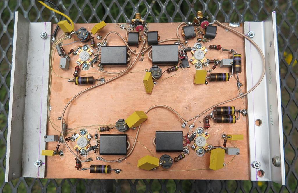
8 Construction details The LNA is built on a 10 x 6 x 1.5 aluminum finned heatsink. The unit if not enclosed in a tight box will not require a fan. I cut holes in the 10 x 6 copper board for the transistors, placed it over the heatsink with fasteners through some aluminum angle for mounting. I then mounted the MRF136s with a dab of heatsink compound. The fasteners for the transistors are exactly centered in-between a pair of heatsink fins screws with a washer just fit in the slots. I have already begun placing some of the bias and power supply components on the upper left corner FET. 8

9 Here is a close-up of one of the MRF136s illustrating how a couple 1206 size, 1 ufd, 60 VDC bypass caps just fit under the gate tab keeping it at a solid RF ground. I had used some of these FETS for other experiments, thus the residue solder on the terminals. I place these caps as soon as possible because the gates are static sensitive, and these caps provide some protection. 9

10 For the transformers, prepare the BN (an Amidon part number) ferrite binocular cores with a red dot to mark the polarity. Cut eight of the RG-178 coax windings to length so they just protrude from the core as shown in the image, and remove some insulation from the ends. Next, I separate out the braid, and remove a section of the inner dielectric from the center conductor. It helps to red dot the same coax stub at both ends in order to keep straight how to make the connections. Connect the braids of one side s red dot stub with the un-dotted braid from the other binocular hole. This is the series connection for the two turn M part of the transformer. The one turn source feedback turn then connects to the source of the transistor. There are two source connections on opposite sides of the transistor, so I use one side for the 22 uh bias connection, and the other side for the transformer connection. Next I take a center conductor from the cold side of the binocular holes and bring it across to the braid of the other coax stub to form the RF output 10
 plus for one of the wires, I")
11 connection. I use 1 ufd, 60 VDC SMD caps to do all the bypassing, and the coupling because these caps have low series inductance, and excellent characteristics up through the GHz frequencies. For the hybrids, I take three different colored wires, and with a power drill, tight twist them for a length to fit eight turns through the BN (Amidon part number) plus for one of the wires, I leave enough for three turns free from the twisted group for the three turn part of the auto-transformer. Four total of these hybrid transformers are needed, and be careful about connecting the wires together or the hybrid will not work correctly. Above is an image of one hybrid. The yellow wire on the left transformer goes to the input SMA 11
12 connector and is the three turn top of the autotransformer part. The three turn part of the other transformer, also yellow, shown on the right of the image goes to the 49.9 Ohm termination resistor. If you want your LNA to invert, then cross-connect the hybrids from input-to-output. That is, put the 0 degree input side hybrid to the top MRF-136s, and on the output side of the top chain, put the output to the 180 degree side of the output hybrid. I prefer this inverting configuration which gives a slightly better S11 return loss. Conclusion The described HF LNA has finally met all of my desires; low noise, and high dynamic range. There are two downsides to the amplifier as designed: 1. The large power draw with 40 VDC at 600 ma, these amps are power pigs, but I do not know how to design around that. Monolithic LNAs from the commercial sources are getting better all the time with respect to OIP3 and noise figure. I do not have knowledge of the internals to accomplish that, but I have not seen one yet that comes anywhere near 60 dbm of IP3. 2. The input impedance is totally reflected by the output impedance, and therefore it is imperative that the output of the amplifiers be terminated in 50 Ohms. I have tried to design an active 50 Ohm termination using various configurations. I configured a P8000 MOSFET as a common gate buffer, and got a really good match to 50 Ohms resistive, but at the drain current adjusted to optimize the Gm at 20 mmhos, the IP3 was only 47 dbm. I believe a complementary-symmetry push-pull configuration with the MRF-136 as the N-Channel device might work, but I could find no P-Channel device for the bottom half. My final solution to the matching problem was to insert 2 db attenuators on the output of each of the amplifiers. This obviously reduces the gain, but at least maintains a decent input match. References 12
13 [1] Intermodulation Distortion Measurements on Modern Spectrum Analyzers Application Note: Rohde & Schwarz [2] D. Norton and A. Podell, Transistor Amplifier with Impedance Matching Transformer, U.S. Patent 3,891,934, June [3] D. Norton, High Dynamic Range Transistor Amplifiers Using Lossless Feedback, Proceedings of the 1975 IEEE International Symposium on Circuits and Systems, pp , [4], High Dynamic Range Transistor Amplifiers With Lossless Feedback, Microwave Journal, pp ,
G6ALU 20W FET PA Construction Information
 G6ALU 20W FET PA Construction Information The requirement This amplifier was designed specifically to complement the Pic-A-Star transceiver developed by Peter Rhodes G3XJP. From the band pass filter an
Principles of Multicoupler Design 2009
 Multicouplers General A multicoupler is a device which connects a signal source to multiple units. The most common arrangement is for splitting a single antenna so that it can feed a number of receivers.
Application Note 1299
 A Low Noise High Intercept Point Amplifier for 9 MHz Applications using ATF-54143 PHEMT Application Note 1299 1. Introduction The Avago Technologies ATF-54143 is a low noise enhancement mode PHEMT designed
A Termination Insensitive Amplifier for Bidirectional Transceivers
 A Termination Insensitive Amplifier for Bidirectional Transceivers Wes Hayward, w7zoi, and Bob Kopski, k3nhi. 26 June 09 (converted to HTML on 27Dec09) The BITX-20 was the first of a now popular class
Construction Manual 4m-Linear-Transverter XV4-15
 Construction Manual 4m-Linear-Transverter XV4-15 Holger Eckardt DF2FQ Kirchstockacherstr. 33 D-85662 Hohenbrunn 3207 Technical data exciter frequency: 21.0... 21.5 MHz RF frequency: 70.0.. 70.5 MHz supply
Agenda 1. AML Amplifier Modification 2. MicroTik mmw Digital Link 3. Hints and Kinks
 Agenda 1. AML Amplifier Modification 2. MicroTik mmw Digital Link 3. Hints and Kinks Greg McIntire, AA5C AA5C@arrl.net November 3, 2018 WWW..ORG 1 AML Amplifier - 1 Surplus Brick Amplifier designed for
Assembly Instructions for the FRB FET FM 70 Watt Amp
 Assembly Instructions for the FRB FET FM 70 Watt Amp 1.) Orient the circuit board with the diagram 2.) Use a narrow chisel tip 25-30 watt soldering iron for assembly 3.) All the small parts are taped onto
PA FAN PLATE ASSEMBLY 188D6127G1 SYMBOL PART NO. DESCRIPTION. 4 SBS /10 Spring nut. 5 19A702339P510 Screw, thread forming, flat head.
 MAINTENANCE MANUAL 851-870 MHz, 110 WATT POWER AMPLIFIER 19D902797G5 TABLE OF CONTENTS Page DESCRIPTION.............................................. Front Page SPECIFICATIONS.................................................
Broadcast Concepts Inc NW 102 Road Suite 4 Medley FL Tel: : Fax Model P50FM42MH-SMA2 FM Pallet Amplifier Module
 Model P50FM42MH-SMA2 FM Pallet Amplifier Module This amplifier module is ideal for driver stages in FM Broadcast transmitters. 86 110MHz 28Volts Pout: 50W CW minimum 40dB Gain Class AB MACOM MRF173 Mosfet
LBI-30398N. MAINTENANCE MANUAL MHz PHASE LOCK LOOP EXCITER 19D423249G1 & G2 DESCRIPTION TABLE OF CONTENTS. Page. DESCRIPTION...
 MAINTENANCE MANUAL 138-174 MHz PHASE LOCK LOOP EXCITER 19D423249G1 & G2 LBI-30398N TABLE OF CONTENTS DESCRIPTION...Front Cover CIRCUIT ANALYSIS... 1 MODIFICATION INSTRUCTIONS... 4 PARTS LIST AND PRODUCTION
IC-781: Installing the Inrad Roofing Filter Mod
 IC-781: Installing the Inrad Roofing Filter Mod The Icom IC-781 roofing filter mod consists of a 6-pole, 4 to 5 khz wide filter followed by a high dynamic range, feedback amplifier. The amplifier provides
Antenna Design for FM-02
 Antenna Design for FM-02 I recently received my FM-02 FM transmitter which I purchased from WLC. I researched the forum on what antennas where being used by the DIY community and found a nice write-up
ERICSSONZ LBI-30398P. MAINTENANCE MANUAL MHz PHASE LOCKED LOOP EXCITER 19D423249G1 & G2 DESCRIPTION TABLE OF CONTENTS
 MAINTENANCE MANUAL 138-174 MHz PHASE LOCKED LOOP EXCITER 19D423249G1 & G2 TABLE OF CONTENTS Page DESCRIPTION... Front Cover CIRCUIT ANALYSIS...1 MODIFICATION INSTRUCTIONS...4 PARTS LIST...5 PRODUCTION
Spectrian 2304 MHz SSPA. Garry C. Hess, K3SIW June 11, 2004
 Spectrian 2304 MHz SSPA Garry C. Hess, K3SIW June 11, 2004 A solid-state power amplifier (SSPA) manufactured by Spectrian can produce on the order of 200 W linear output 1 at 2304 MHz with little modification.
MGA-632P8 1.9 GHz low noise amplifier Application Note 5295
 MGA-63P8 1.9 GHz low noise amplifier Application Note 595 Introduction The MGA-63P8 is a GaAs EPHEMT LNA with integrated active bias. The target applications are Tower Mounted Amplifiers and LNAs in cellular
MFJ 259 Operation & Simplified Calibration
 MFJ 259 Operation & Simplified Calibration Bill Leonard N0CU NA0TC 2014 TechFest 1 What Will Be Covered Part 1: Operation What is an MFJ 259 What Does It Measure Impedance & Admittance How Does It Work
Application Note 5295
 MGA-63P8 1.9 GHz low noise amplifier using MGA-63P8 Application Note 595 Introduction The MGA-63P8 is a GaAs EPHEMT with an integrated active bias. The target applications are Tower Mounted Amplifier /
High Intercept Low Noise Amplifier for 1.9 GHz PCS and 2.1 GHz W-CDMA Applications using the ATF Enhancement Mode PHEMT
 High Intercept Low Noise Amplifier for 1.9 GHz PCS and 2.1 GHz W-CDMA Applications using the ATF-55143 Enhancement Mode PHEMT Application Note 1241 Introduction Avago Technologies ATF-55143 is a low noise
Application Note 5303
 MGA-6P8 9 MHz low noise amplifier using MGA-6P8 Application Note 5 Introduction The MGA-6P8 is a GaAs EPHEMT with an integrated active bias. The target applications are Tower Mounted Amplifier / Main LNA
Fun with Preamps A great way to pass a cold winter afternoon is to homebrew some preamps Designs and Benchmarks Construction The W7IUV Preamp
 Fun with Preamps A great way to pass a cold winter afternoon is to homebrew some preamps Built two preamps today. I ve been thinking of building a couple as a general interest project and today turned
CHAPTER - 6 PIN DIODE CONTROL CIRCUITS FOR WIRELESS COMMUNICATIONS SYSTEMS
 CHAPTER - 6 PIN DIODE CONTROL CIRCUITS FOR WIRELESS COMMUNICATIONS SYSTEMS 2 NOTES 3 INTRODUCTION PIN DIODE CONTROL CIRCUITS FOR WIRELESS COMMUNICATIONS SYSTEMS Chapter 6 discusses PIN Control Circuits
DC Injector (Bias Tee) kit. Technical Manual
 kit. Technical Manual") DC Injector (Bias Tee) kit Technical Manual Document Author Dave Powis, G4HUP Date 7 Jan 2017 Version Issue 2_0 Document Ref HUP-05-020 http://huprf.com Tel +44 (0)1473 737717 g4hup@outlook.com Contents
DC Injector (Bias Tee) kit Technical Manual Document Author Dave Powis, G4HUP Date 7 Jan 2017 Version Issue 2_0 Document Ref HUP-05-020 http://huprf.com Tel +44 (0)1473 737717 g4hup@outlook.com Contents
Medium Power 137kHz Linear Power Amplifier G4JNT Sept 2010
 Medium Power 137kHz Linear Power Amplifier G4JNT Sept 2010 This project was conceived on the back of an envelope after running a WSPR beacon thorough my 600 Watt switch mode Power Amplifier, and setting
10 GHz LNA for Amateur Radio by K5TRA
 Introduction Ham radio operation on 10 GHz is somewhat exotic. This is far removed from global short-wave communication below 30 MHz, or regional VHF and UHF communication. Despite the arcane nature of
ATF High Intercept Low Noise Amplifier for the MHz PCS Band using the Enhancement Mode PHEMT
 ATF-54143 High Intercept Low Noise Amplifier for the 185 191 MHz PCS Band using the Enhancement Mode PHEMT Application Note 1222 Introduction Avago Technologies ATF-54143 is a low noise enhancement mode
Application Note 5057
 A 1 MHz to MHz Low Noise Feedback Amplifier using ATF-4143 Application Note 7 Introduction In the last few years the leading technology in the area of low noise amplifier design has been gallium arsenide
Building a Bitx20 Version 3
 Building a Bitx20 Version 3 The board can be broken into sections and then built and tested one section at a time. This will make troubleshooting easier as any problems will be confined to one small section.
Assembly Instructions for the 1.5 Watt Amplifier Kit
 Assembly Instructions for the 1.5 Watt Amplifier Kit 1.) All of the small parts are attached to a sheet of paper indicating both their value and id. 2.) Leave the parts affixed to the paper until you are
The 144MHz Anglian 3 transverter
 The 144MHz Anglian 3 transverter A high performance 144/28MHz transverter G4DDK document issue 1 12/9/16 Introduction Anglian 3 is an update to the 144MHz Anglian 2 transverter. The Anglian 2 is no longer
Demo Circuit DC550A Quick Start Guide.
 May 12, 2004 Demo Circuit DC550A. Introduction Demo circuit DC550A demonstrates operation of the LT5514 IC, a DC-850MHz bandwidth open loop transconductance amplifier with high impedance open collector
Construction Manual 6m-Linear-Transverter XV6/10
 Construction Manual 6m-Linear-Transverter XV6/10 Holger Eckardt DF2FQ Kirchstockacherstr. 33 D-85662 Hohenbrunn 2606 Technical data exciter frequency: 28... 30 MHz RF frequency: 50... 52 MHz supply voltage:
My experience with the ANC-4 on 50 MHz Rev. 1
 My experience with the ANC-4 on 50 MHz Rev. 1 by Antonio Vernucci, I0JX 1. General The ANC-4 (Antenna Noise Canceller - 4) is intended to reduce the impairment of weak DX signals reception caused by local
Yana Dongles Tom Berger K1TRB (c)2016 v171227
2016 v171227") Yana Dongles Tom Berger K1TRB (c)2016 v171227 These notes elaborate some items described in the Build notes, and add some more dongles enhancing Yana. Every effort has been exerted to save on the cost
Yana Dongles Tom Berger K1TRB (c)2016 v171227 These notes elaborate some items described in the Build notes, and add some more dongles enhancing Yana. Every effort has been exerted to save on the cost
MFJ-219/219N 440 MHz UHF SWR Analyzer TABLE OF CONTENTS
 MFJ-219/219N 440 MHz UHF SWR Analyzer TABLE OF CONTENTS Introduction...2 Powering The MFJ-219/219N...3 Battery Installation...3 Operation Of The MFJ-219/219N...4 SWR and the MFJ-219/219N...4 Measuring
Modifying the Qualcomm 1W Ku-Band PA for use on 3.4, 5.7 or 10.3 GHz
 Web Version 10-9-2001 Modifying the Qualcomm 1W Ku-Band PA for use on 3.4, 5.7 or 10.3 GHz K-Banke- 07/13/01 Hundreds of Ku-Band Qualcomm 1 watt power amplifiers have been modified and found their way
ATF-531P8 E-pHEMT GaAs FET Low Noise Amplifier Design for 800 and 900 MHz Applications. Application Note 1371
 ATF-31P8 E-pHEMT GaAs FET Low Noise Amplifier Design for 8 and 9 MHz Applications Application Note 1371 Introduction A critical first step in any LNA design is the selection of the active device. Low cost
HAMTRONICS LPA 2-25R REPEATER POWER AMPLIFIER: ASSEMBLY, INSTALLATION, & MAINTENANCE
 HAMTRONICS LPA 2-25R REPEATER POWER AMPLIFIER: ASSEMBLY, INSTALLATION, & MAINTENANCE GENERAL INFORMATION. The Power Amplifier is a class C device designed to be installed as an integral part of a transmitter
Low Noise Amplifiers for 2304, 3456, 5760, and MHz using the ATF PHEMT by Al Ward WB5LUA
 Low Noise Amplifiers for 2304, 3456, 5760, and 10368 MHz using the by Al Ward INTRODUCTION The Hewlett-Packard device is described in a series of low noise amplifiers for 2304, 3456, 5760, and 10368 MHz.
HAMTRONICS R901 FM RECEIVER INSTALLATION, OPERATION, AND MAINTENANCE INSTRUCTIONS
 HAMTRONICS R901 FM RECEIVER INSTALLATION, OPERATION, AND MAINTENANCE INSTRUCTIONS GENERAL INFORMATION. The R901 is a commercial grade single-channel fm receiver for the 902-928 MHz amateur band and the
High-Power Directional Couplers with Excellent Performance That You Can Build
 High-Power Directional Couplers with Excellent Performance That You Can Build Paul Wade W1GHZ 2010 w1ghz@arrl.net A directional coupler is used to sample the RF energy travelling in a transmission line
Improving CDM Measurements With Frequency Domain Specifications
 Improving CDM Measurements With Frequency Domain Specifications Jon Barth (1), Leo G. Henry Ph.D (2), John Richner (1) (1) Barth Electronics, Inc, 1589 Foothill Drive, Boulder City, NV 89005 USA tel.:
1 TRANSISTOR CIRCUITS
 FM TRANSMITTERS The first group of circuits we will discuss are FM TRANSMITTERS. They can be called SPY TRANSMITTERS, FM BUGS, or a number of other interesting names. They all do the same thing. They transmit
1 of 7 12/20/ :04 PM
 1 of 7 12/20/2007 11:04 PM Trusted Resource for the Working RF Engineer [ C o m p o n e n t s ] Build An E-pHEMT Low-Noise Amplifier Although often associated with power amplifiers, E-pHEMT devices are
Introduction Introduction to radio frequencies p. 3 What are the 'radio frequencies'? p. 3 Why are radio frequencies different? p.
 Foreword p. xi Preface p. xiii Introduction Introduction to radio frequencies p. 3 What are the 'radio frequencies'? p. 3 Why are radio frequencies different? p. 3 What this book covers p. 3 Signals and
Technician Licensing Class T9
 Technician Licensing Class T9 Amateur Radio Course Monroe EMS Building Monroe, Utah January 11/18, 2014 January 22, 2014 Testing Session Valid dates: July 1, 2010 June 30, 2014 Amateur Radio Technician
ARNSW Balun Day. Balun construction
 ARNSW Balun Day Balun construction Typical Baluns All built from locally available components. Balun uses Most baluns are used to match the 50Ω output of a transceiver to an antenna. A centre fed dipole
The ROSE 80 CW Transceiver (Part 1 of 3)
") Build a 5 watt, 80 meter QRP CW Transceiver!!! Page 1 of 10 The ROSE 80 CW Transceiver (Part 1 of 3) Build a 5 watt, 80 meter QRP CW Transceiver!!! (Designed by N1HFX) A great deal of interest has been
Build a 5 watt, 80 meter QRP CW Transceiver!!! Page 1 of 10 The ROSE 80 CW Transceiver (Part 1 of 3) Build a 5 watt, 80 meter QRP CW Transceiver!!! (Designed by N1HFX) A great deal of interest has been
Efficiency: 68% Temperature Range: +0 to 60 C Max VSWR: 5:1. Class: Supply Voltage:
 Part Number Revision 2.C Release Date July 11 2007 Revision Notes - updated new format Amplifier Name Technical Specifications Summary Frequency Range: P1dB: Class: Supply Voltage: 88-108 MHz 750 Watts
RADIO RECEIVERS ECE 3103 WIRELESS COMMUNICATION SYSTEMS
 RADIO RECEIVERS ECE 3103 WIRELESS COMMUNICATION SYSTEMS FUNCTIONS OF A RADIO RECEIVER The main functions of a radio receiver are: 1. To intercept the RF signal by using the receiver antenna 2. Select the
My Pre-amp doesn t work!
 My Pre-amp doesn t work! A design, troubleshooting, and repair guide for all modern day GaAs FET or PHEMPT type low noise amplifiers. DEMI by N2CEI, Steve Kostro PREFACE For anyone that considers themselves
SPECIFICATIONS: Subcarrier Frequency 5.5MHz adjustable, FM Modulated +/- 50KHz. 2nd 11MHz >40dB down from 5.5MHz
 Mini-kits AUDIO / SUBCARRIER KIT EME75 Version4 SPECIFICATIONS: Subcarrier Frequency 5.5MHz adjustable, FM Modulated +/- 50KHz Subcarrier Output 1.5v p-p Output @ 5.5MHz DESCRIPTION & FEATURES: The Notes
Application Note 5499
 MGA-31389 and MGA-31489 High-Gain Driver Amplifier Using Avago MGA-31389 and MGA-31489 Application Note 5499 Introduction The MGA-31389 and MGA-31489 from Avago Technologies are.1 Watt flat-gain driver
Data Sheet SC5317 & SC5318A. 6 GHz to 26.5 GHz RF Downconverter SignalCore, Inc. All Rights Reserved
 Data Sheet SC5317 & SC5318A 6 GHz to 26.5 GHz RF Downconverter www.signalcore.com 2018 SignalCore, Inc. All Rights Reserved Definition of Terms 1 Table of Contents 1. Definition of Terms... 2 2. Description...
Building the Sawdust Regenerative Receiver
 Building the Sawdust Regenerative Receiver Introduction The Sawdust is a super regenerative receiver using the basic Armstrong design architecture. The receiver uses one toroidal transformer to provide
Modifying The Heath HA-14 For 6 Meters Greg Chartrand - W7MY 4/22/07
 Introduction The Heathkit HA-14 was one of the few electron tube linear amplifiers intended for mobile use but few were purchased with the 12 volt mobile power supply. Most hams bought the HA-14 for base
Reference Design for MHz Push-Pull 600 W RF Amplifier IXZ318N50L
 1609 Oakridge Drive, Suite 100 Fort Collins, CO. 80525 (970) 493-1901 www.ixyscolorado.com Reference Design for 13.56 MHz Push-Pull 600 W RF Amplifier IXZ318N50L Martin Jones R&D/Application Engineering
Low Power RF Transceivers
 Low Power RF Transceivers Mr. Zohaib Latif 1, Dr. Amir Masood Khalid 2, Mr. Uzair Saeed 3 1,3 Faculty of Computing and Engineering, Riphah International University Faisalabad, Pakistan 2 Department of
AM036MX-QG-R 1 WATT, 2 GHz POWER AMPLIFIER
 AM036MX-QG-R 1 WATT, 2 GHz POWER AMPLIFIER AN136 January 2011 REV 3 INTRODUCTION This application note describes the design of a one-watt, single stage power amplifier at 2GHz using AMCOM s low cost surface
HF Receivers, Part 2
 HF Receivers, Part 2 Superhet building blocks: AM, SSB/CW, FM receivers Adam Farson VA7OJ View an excellent tutorial on receivers NSARC HF Operators HF Receivers 2 1 The RF Amplifier (Preamp)! Typical
VCO Design Project ECE218B Winter 2011
 VCO Design Project ECE218B Winter 2011 Report due 2/18/2011 VCO DESIGN GOALS. Design, build, and test a voltage-controlled oscillator (VCO). 1. Design VCO for highest center frequency (< 400 MHz). 2. At
Hendricks QRP Kits BITX20A to BITX17A Conversion Instructions
 Hendricks QRP Kits BITX20A to BITX17A Conversion Instructions 30 November 2008 Converting your BITX20A Kit to a BITX17A Kit is not all that complex. It only requires that you change crystals and some resonance
Hardware Store 40m Magnetic Loop Antenna for Regional and EMCOM Use. Richard Bono NO5V. QST Antenna Design Competition 80 through 10 meter entry
 Hardware Store 40m Magnetic Loop Antenna for Regional and EMCOM Use Richard Bono NO5V QST Antenna Design Competition 80 through 10 meter entry Overview: This describes a field deployable magnetic loop
Application Note 5106
 ATF-50189 2.4 GHz High-linearity Second-stage LNA/Driver using the ATF-50189 Application Note 5106 Introduction Avago Technologies ATF-50189 is a high linearity, medium power, low noise E-pHEMT FET in
4/25/2012. Supplement T9. 2 Exam Questions, 2 Groups. Amateur Radio Technician Class T9A: T9A: T9A: T9A:
 Amateur Radio Technician Class Element 2 Course Presentation ti ELEMENT 2 SUB-ELEMENTS Technician Licensing Class Supplement T9 Antennas, Feedlines 2 Exam Questions, 2 Groups T1 - FCC Rules, descriptions
Exercise 1: RF Stage, Mixer, and IF Filter
 SSB Reception Analog Communications Exercise 1: RF Stage, Mixer, and IF Filter EXERCISE OBJECTIVE DISCUSSION On the circuit board, you will set up the SSB transmitter to transmit a 1000 khz SSB signal
Technician License. Course
 Technician License Course Technician License Course Chapter 4 Lesson Plan Module - 9 Antenna Fundamentals Feed Lines & SWR The Antenna System The Antenna System Antenna: Transforms current into radio waves
HAMTRONICS TB901 FM EXCITER INSTALLATION, OPERATION, & MAINTENANCE
 HAMTRONICS TB901 FM EXCITER INSTALLATION, OPERATION, & MAINTENANCE GENERAL INFORMATION. The TB901 is a single-channel low power fm transmitter (exciter) designed to provide 300-600 milliwatts continuous
CX7 Troubleshooting Index
 CX7 Troubleshooting Index Modification S/1 Newsletter Guide Board Description A/TO A/TO MODE Intermod V1,12 P4.4 A11 Shut off one 35 MHz osc in receive, done sn 244 A/TO Spur V1,12 P1 Reduce A/TO spur,
Model FM350 FM Broadcast Pallet Amplifier
 Model FM350 FM Broadcast Pallet Amplifier Designed for FM radio transmitters, this amplifier incorporates the latest technology from ST Microelectronics. (Formerly known as SGS Thompson). 86 110MHz 48
KN-Q10 Assembly Manual
 KN-Q10 Assembly Manual Translated by Adam Rong, BD6CR/4 with permission from Ke Shi, BA6BF Edited by Stephen, VK2RH Revision B, Oct 14, 2010 Thank you for purchasing the KN-Q10 4 Band SSB/CW Dual Mode
ECE 145A/218A, Lab Project #1b: Transistor Measurement.
 ECE 145A/218A, Lab Project #1b: Transistor Measurement. September 28, 2017 OVERVIEW... 2 GOALS:... 2 SAFETY PRECAUTIONS:... 2 READING:... 2 TRANSISTOR RF CHARACTERIZATION.... 3 DC BIAS CIRCUITS... 3 TEST
Application Note 5011
 MGA-62563 High Performance GaAs MMIC Amplifier Application Note 511 Application Information The MGA-62563 is a high performance GaAs MMIC amplifier fabricated with Avago Technologies E-pHEMT process and
Tuning a 160M full sized vertical with strong AM broadcast RF present on the antenna. Jay Terleski, WX0B
 Tuning a 160M full sized vertical with strong AM broadcast RF present on the antenna. Jay Terleski, WX0B I often get asked about how to match a ¼ WL vertical to a 50 ohm transmission line and what to do
RFM HSD MHz 350W Class A/AB High Performance Amplifier with High Speed Disable
 Class A/AB 350W linear amplifier Fast output disable,
Transmission Line Signal Sampling By Don Steinbach, AE6PM
 Transmission Line Signal Sampling By Don Steinbach, AE6PM When I was finalizing the mechanical layout of my remotely-operated 3-position coaxial antenna switch (Fig. 1), I wanted to include a way to bring
Chapter 6 Antenna Basics. Dipoles, Ground-planes, and Wires Directional Antennas Feed Lines
 Chapter 6 Antenna Basics Dipoles, Ground-planes, and Wires Directional Antennas Feed Lines Some General Rules Bigger is better. (Most of the time) Higher is better. (Most of the time) Lower SWR is better.
RF PRO-1B INSTALLATION INSTRUCTIONS
 P ixel TECHNOLOGIES RF PRO-1B INSTALLATION INSTRUCTIONS This active magnetic loop antenna is designed for reception of signals over the range of 50 khz to 30 MHz. It includes a very high dynamic range
IC-765: Installing the Inrad Roofing Filter Mod
 IC-765: Installing the Inrad Roofing Filter Mod The Icom IC-765 roofing filter mod consists of a 6-pole, 4 khz wide filter followed by a high dynamic range, feedback amplifier. The amplifier provides enough
DEM TC DEM TRANSVERTER CONTROL
 DEM TC DEM TRANSVERTER CONTROL The DEM Transverter Control (DEM TC) is the circuit board that controls all transverter functions in the DEMI 2.3 GHz. -10 GHz. transverters. It was designed with many options
MHz (FM BAND) 50 Volts Input/output 50 ohms Pout: 1250W minimum Up to 85% efficiency 22dB Gain NXP MRF1K50 Mosfet Planar RF Transformers
 50 Volts Input/output 50 ohms Pout: 1250W minimum Up to 85% efficiency 22dB Gain NXP MRF1K50 Mosfet Planar RF Transformers") Model MRF1K50-PLA FM Pallet Amplifier This amplifier module is ideal for final output stages in FM Broadcast Applications. 87.5 108.1MHz (FM BAND) 50 Volts Input/output 50 ohms Pout: 1250W minimum Up to
Model MRF1K50-PLA FM Pallet Amplifier This amplifier module is ideal for final output stages in FM Broadcast Applications. 87.5 108.1MHz (FM BAND) 50 Volts Input/output 50 ohms Pout: 1250W minimum Up to
Stand Alone RF Power Capabilities Of The DEIC420 MOSFET Driver IC at 3.6, 7, 10, and 14 MHZ.
 Abstract Stand Alone RF Power Capabilities Of The DEIC4 MOSFET Driver IC at 3.6, 7,, and 4 MHZ. Matthew W. Vania, Directed Energy, Inc. The DEIC4 MOSFET driver IC is evaluated as a stand alone RF source
Some Thoughts on Electronic T/R Circuits
 Some Thoughts on Electronic T/R Circuits Wes Hayward, w7zoi, November 3, 2018 Abstract: Several schemes have been used to switch an antenna between a receiver and transmitter. A popular scheme with low
HF Power Amplifier (Reference Design Guide) RFID Systems / ASP
 RFID Systems / ASP") 16 September 2008 Rev A HF Power Amplifier (Reference Design Guide) RFID Systems / ASP 1.) Scope Shown herein is a HF power amplifier design with performance plots. As every application is different and
16 September 2008 Rev A HF Power Amplifier (Reference Design Guide) RFID Systems / ASP 1.) Scope Shown herein is a HF power amplifier design with performance plots. As every application is different and
A GOOD REGENERATIVE RECEIVER WITH SIMPLE FINE TUNING (2008)
") A GOOD REGENERATIVE RECEIVER WITH SIMPLE FINE TUNING (2008) A good SSB-CW-AM regenerative receiver with a fine tuning by moving the wooden stick with a grounded piece of PCB towards the coil. A good regenerative
A GOOD REGENERATIVE RECEIVER WITH SIMPLE FINE TUNING (2008) A good SSB-CW-AM regenerative receiver with a fine tuning by moving the wooden stick with a grounded piece of PCB towards the coil. A good regenerative
Introduction to Surface Acoustic Wave (SAW) Devices
 Devices") May 31, 2018 Introduction to Surface Acoustic Wave (SAW) Devices Part 7: Basics of RF Circuits Ken-ya Hashimoto Chiba University k.hashimoto@ieee.org http://www.te.chiba-u.jp/~ken Contents Noise Figure
May 31, 2018 Introduction to Surface Acoustic Wave (SAW) Devices Part 7: Basics of RF Circuits Ken-ya Hashimoto Chiba University k.hashimoto@ieee.org http://www.te.chiba-u.jp/~ken Contents Noise Figure
TS-930: Installing the Inrad Roofing Filter Mod
 TS-930: Installing the Inrad Roofing Filter Mod The TS-930 roofing filter mod consists of a 6 pole, 4 to 5 khz wide filter followed by a high dynamic range, feedback amplifier. The amplifier provides enough
Technician License Course Chapter 4. Lesson Plan Module 9 Antenna Fundamentals, Feed Lines & SWR
 Technician License Course Chapter 4 Lesson Plan Module 9 Antenna Fundamentals, Feed Lines & SWR The Antenna System Antenna: Transforms current into radio waves (transmit) and vice versa (receive). Feed
P D Storage Temperature Range T stg 65 to +150 C Operating Junction Temperature T J 200 C
 SEMICONDUCTOR TECHNICAL DATA Order this document by MRF151/D The RF MOSFET Line N Channel Enhancement Mode MOSFET Designed for broadband commercial and military applications at frequencies to 175 MHz.
A 2.4 GHZ RECEIVER IN SILICON-ON-SAPPHIRE MICHAEL PETERS. B.S., Kansas State University, 2009 A REPORT
 A 2.4 GHZ RECEIVER IN SILICON-ON-SAPPHIRE by MICHAEL PETERS B.S., Kansas State University, 2009 A REPORT submitted in partial fulfillment of the requirements for the degree MASTER OF SCIENCE Department
Designing a 960 MHz CMOS LNA and Mixer using ADS. EE 5390 RFIC Design Michelle Montoya Alfredo Perez. April 15, 2004
 Designing a 960 MHz CMOS LNA and Mixer using ADS EE 5390 RFIC Design Michelle Montoya Alfredo Perez April 15, 2004 The University of Texas at El Paso Dr Tim S. Yao ABSTRACT Two circuits satisfying the
14 MHz Single Side Band Receiver
 EPFL - LEG Laboratoires à options 8 ème semestre MHz Single Side Band Receiver. Objectives. The objective of this work is to calculate and adjust the key elements of an Upper Side Band Receiver in the
Application Note 5012
 MGA-61563 High Performance GaAs MMIC Amplifier Application Note 5012 Application Information The MGA-61563 is a high performance GaAs MMIC amplifier fabricated with Avago Technologies E-pHEMT process and
4454 P500-UHF-17-A. Frequency Range: MHz. Efficiency: 36% Temperature Range: -10 to 55 C Max VSWR: 3:1. Supply Voltage: 32.
 Part Number Revision 0.e Release Date December 13, 2007 This document applies to 4454 and 5029 Revision Notes: 0.b Full production release, Apr 07. 0.c Revised Specs May 07. Revised Integration Instructions
A 2.5 W LDMOS MICROWAVE TOTEM-POLE PUSH- PULL RF POWER AMPLIFIER
 A 2.5 W LDMOS MICROWAVE TOTEM-POLE PUSH- PULL RF POWER AMPLIFIER Gavin T. Watkins Toshiba Research Europe Limited, 32 Queen Square, Bristol, BS1 4ND, UK Gavin.watkins@toshiba-trel.com RF push-pull power
Building and Operating: LF Converter An SA612 based LF up-converter from Jackson Harbor Press
 Introduction: Building and Operating: LF Converter An SA612 based LF up-converter from Jackson Harbor Press The frequencies below the broadcast band are covered by few receivers on the market - those that
Improved Ionospheric Propagation With Polarization Diversity, Using A Dual Feedpoint Cubical Quad Loop
 Improved Ionospheric Propagation With Polarization Diversity, Using A Dual Feedpoint Cubical Quad Loop by George Pritchard - AB2KC ab2kc@optonline.net Introduction This Quad antenna project covers a practical
Understanding Power Splitters
 Understanding Power Splitters How they work, what parameters are critical, and how to select the best value for your application. Basically, a 0 splitter is a passive device which accepts an input signal
HAMTRONICS R451 UHF FM RECEIVER: INSTALLATION, OPERATION, & MAINTENANCE
 HAMTRONICS R451 UHF FM RECEIVER: INSTALLATION, OPERATION, & MAINTENANCE FUNCTIONAL DESCRIPTION. The R451 is a premium, commercial- grade single-channel uhf fm receiver. It features a GaAs FET rf amplifier
HF Amateur SSB Receiver
 HF Amateur SSB Receiver PCB Set for radio club project http://rhelectronics.net PCB for DIY HF Amateur SSB Receiver 20M The receiver is a simple syperheterodyne type with quartz crystal filter. The circuit
EE12: Laboratory Project (Part-2) AM Transmitter
 AM Transmitter") EE12: Laboratory Project (Part-2) AM Transmitter ECE Department, Tufts University Spring 2008 1 Objective This laboratory exercise is the second part of the EE12 project of building an AM transmitter in
EE12: Laboratory Project (Part-2) AM Transmitter ECE Department, Tufts University Spring 2008 1 Objective This laboratory exercise is the second part of the EE12 project of building an AM transmitter in