We are delighted that you have decided to purchase a power supply unit from PowerBox Systems.
|
|
|
- Scot Crawford
- 6 years ago
- Views:
Transcription


1
2 Dear customer, We are delighted that you have decided to purchase a power supply unit from PowerBox Systems. We hope you have many hours of pleasure and great success with your new PowerBox. 1. Product description The PowerBox Competition, Cockpit and Professional have undergone constant development since their introduction in For example, the menu system has been improved, and new functions such as telemetry and the door sequencer assistant have been added. These PowerBoxes are modern power supply systems which contain all the electronic components required for modern receivers, servos and models. All the essential components for a secure power supply voltage - ICs, micro-controllers and electronic circuits - are duplicated. The outstanding features of this High-End power supply unit are a raft of the latest innovations such as an integral high-resolution graphic OLED screen, door sequencer capable of multitasking with Setup Assistant, four match-channels and the facility to bind to the downlink channels of various RC system manufacturers. -02-
3 Features: - Integral high-resolution graphic OLED screen with 128 x 64 pixels - Particularly user-friendly menu-based programming using the SensorSwitch - Door sequencer: six freely programmable outputs with set-up assistant - Channel lock when undercarriage is retracted - 11 channels inclusive one channel for the doorsequencer in the Cockpit Version - 12 channels in the Competition version - 8 channels in the Professional version - Signal amplification and interference suppression for all channels - Synchronised servo output for totally synchronous servo response - Variable frame rate, range 9 ms - 21 ms - 16-bit processor for fast, high-resolution signal processing - Four match-channels, each for two servos. Accurate adjustment of all eight servos - Double regulated output voltage for receivers and servos - Can be connected to Spektrum, HoTT and Multiplex MSB downlink channel bus systems - Direct transmission of battery voltages and capacities (not Professional) to the transmitter - Separate voltage and capacity (not Professional) displays for each battery - Software-selectable servo voltage: 5.9 V or 7.4 V - Minimum value memory displays any voltage collapses - Large-area heat-sinks for high regulator power - Regulator monitor, regulator malfunction indicator - Support for three battery types: LiPo, NiMH / NiCd, LiFePo - Suppresses any servo feedback currents which might develop - Can be updated using the PowerBox USB Interface -03-


4 2. Connections, controls The following illustrations show the essential sockets and controls: Door sequencer outputs Servo sockets OLED screen Battery input, Battery 1 and 2 Receiver inputs SET-Button Power-on status LEDs Switch buttons for Battery 1 and 2 Left: socket fot Spektrum telemetry Right: SensorSwitch socket -04- Connector for Multiplex Telemetrie, MSB and HoTT
5 3. First steps, the unit in use: In the following instructions we do not differentiate between the PowerBox Cockpit, Competition and Professional, since the method of programming the three units is absolutely identical. The only difference is that the PowerBox Cockpit includes the door sequencer function Connections Plug the batteries into the MPX connectors on the backer with correct polarity. We recommend PowerBox Batteries of 1500mAh, 2800mAh, 3200 mah or 4000mAh capacity. If you prefer to use other makes of battery, or packs you have assembled yourself, please take particular care over polarity - it is always better to check twice rather than make a mistake. If you connect a battery to the backer incorrectly, this will immediately ruin the associated regulator. The unit does not feature reverse polarity protection, as this minimises power losses between battery and backer. The + markings are printed clearly on the case cover. Connect the SensorSwitch to the appropriate red socket. Note that the ribbon cable must run upwards. In models subject to powerful vibration we recommend that you secure the ribbon cable at a minimum of one point in order to prevent the connector working loose and falling out. Although this would have no effect on the switched state of the backer, it would prevent you switching it off The procedure for switching on and off The method of switching the unit on and off is very simple, and the process effectively eliminates the possibility of changing the backer s status accidentally. This is the procedure Locate the SET button on the SensorSwitch and hold it pressed in until the central LED glows red. Now press buttons I and II in turn to switch the backer on. Repeat the procedure to switch off: hold the SET button pressed in, wait until the central LED glows red, then confirm by pressing buttons I and II in turn. -05-

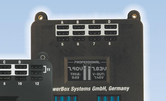
6 Your PowerBox stores the last switched state (on or off). That means: if the backer is switched off using the SensorSwitch, it stays switched off. Once switched on, the backer can only be turned off again using the switch unit. Intermittent contacts or interruptions in the power supply cannot cause the backer to be switched off Main screen display When switched on, the unit s integral screen shows this display: Key to the individual display points: - Digital voltage display: This extremely accurate display allows you to read off the voltage of the battery directly, i.e. the voltage which is present at the input of the PowerBox. - Graphic voltage display: A brief glance into the model provides you with information about the batteries state of charge. This display is always correct for the type of battery you have selected. This means that the bar will extend right to the top of the box if the connected battery is fully charged - assuming that you have set the correct battery type. If the bar only fills the bottom third of the box, then the corresponding battery is almost flat. This indicator is supplemented by the residual capacity display. - Residual battery capacity (Cockpit/Competition only): This display shows the momentary capacity value of the battery - again, assuming that you have previously set the battery type correctly. This display is capable of providing very accurate information about the remaining battery capacity, although ageing effects or defective batteries may falsify the value. In practice this means that you should always take both values into account: if the remaining capacity appears to be high, but the voltage has already fallen to a low level, you should consider it an urgent necessity to check the battery more closely. -06-
7 - Graphic indicator of battery charge state: This display is set to match the capacity you previously entered for the batteries connected to the backer. Assuming that the battery is of good quality, this means: if the bar only reaches the half-way point, then the battery is still half-full. - Operating time: This figure shows the elapsed time since the last RESET. It is important always to carry out a RESET after each battery charge process. - Output voltage: This value displays the backer s exact output voltage. The voltage fed to the servos and receiver is the exact value displayed here. Note: The residual capacity of the two batteries as displayed on the screen is likely to drift apart as the packs are discharged; this is due to minor differences in the rate of discharge of the batteries through the PowerBox. This by no means indicates a fault in the PowerBox; in fact it proves that the system features genuine redundancy. Here at PowerBox Systems we take great trouble to compensate for manufacturing tolerances between the two regulators, but it is never possible to produce a system which is completely devoid of tolerances. The only method of discharging two batteries at 100% identical rates is to use a system fitted with only one regulator. However, such systems cannot be claimed to offer redundancy! 3.4. After the charge process The PowerBox must be reset after each charge process, otherwise it is impossible for the unit to display reliable values for energy consumption and operating times. This is the reset procedure: With the system switched on, locate both buttons I and II on the SensorSwitch and press them simultaneously; hold them pressed in until the following screen display appears: -07-
8 3.5. Basic settings The PowerBox Cockpit, Competition and Professional feature a new kind of graphic OLED screen, intended to do away with old-fashioned programming methods based on flashing LED codes, morse code beeps or obsolete mechanical jumpers. The screen provides the basis for an extremely user-friendly control system, and eliminates the need for a supplementary setup unit or programming device. The SensorSwitch is employed as a convenient means of entering settings within the menu system, and since the SensorSwitch is always used as the main ON / OFF switch, it is always installed in the model, so you cannot forget it. Wherever possible the screen provides full information in English; few abbreviations are used. The overall result is an intuitive method of programming which is a great advantage at the flying field, as you will rarely need to consult the operating instructions. This is the basic rule in programming: buttons I and II are used to move the cursor or change values, while the SET button is used to select or confirm your inputs. The breadth of functions offered by the PowerBox Cockpit, Competition and Professional is enormous, but the unit is by no means difficult to operate. To provide a clear idea of the sequence required in order to use the backer, we have drawn up a brief list of operations 1. Battery setting Point Servo matching and door sequencer Points 4 and 5 3. Telemetry settings Point Battery settings These settings should always be entered first, so that you have an accurate view of the state of the battery while you carry out further adjustments. In the screenshot below you will see the default settings of the PowerBox Cockpit, Competition and Professional. If you wish to change them, this is the procedure: -08-
 lines up with Power Manager, then press the SET button.")
9 - Switch both batteries on. - Press the SET button and hold it pressed in until the following display appears: - Press button II until the cursor (hollow circular ring) lines up with Power Manager, then press the SET button. The following display now appears: If you wish to change one of the settings, use buttons I and II to move the cursor to the appropriate menu point, then press the SET button to select it (cursor changes to a solid disc). You can now alter the value using buttons I and II. Once you have selected the desired value, press the SET button to confirm it; this saves (stores) the new value. Select the menu point OK to return to the main menu. NOTE: the presence of a solid disc (instead of a ring) indicates that you are in a menu point. It is possible to alter a value more quickly by holding one of the two buttons I or II pressed in; the value then starts to change slowly in the corresponding direction, and the rate of change accelerates with time. -09-
10 Key to the individual menu points: - Chemistry: this is where you set the battery type. Three different types of battery are available: Two-cell LiPo Five-cell NiMH Two-cell LiFe - Capacity: you can enter the nominal capacity of your batteries at this point. - Output voltage: you can select the output voltage to 7.4V or 5.9V CAUTION: if you intend to select the 7.4V output voltage, please ensure before you make the change that all the consumer units connected to the unit, i.e. all servos, receivers and gyros, are compatible with a 7.4V supply. Information on this subject can be found in the instructions for these components supplied by the manufacturers. Compared with a direct, unregulated voltage of 8.4V, the advantage of a stabilised 7.4V supply is that the voltage is always constant. This means that the servos in your model always run at the same speed and with the same torque, regardless of the manoeuvres you fly. For example, if you were to operate the servos on the unregulated voltage of LiPo batteries, their running characteristics would alter as the freshly charged batteries steadily discharged during the flight. Another major advantage of a regulated 7.4V voltage is that it completely eliminates damaging voltage peaks (spikes); this extends the useful life of the servos substantially. -10-
11 4. Servo Match Function The Servo-Match function provides the facility for adjusting the centre position and end-points of the servos connected to the backer. If you have a model aircraft with more than one servo per control surface, this makes it possible to set up multiple servos to move to identical positions at identical times. Since this ensures that the servos do not work against each other, their effective life is increased, and more power is available to move the control surfaces; matched servos also draw lower current. It is also possible to reverse the direction of rotation of individual servos. This function is useful if you wish to employ fewer channels at the transmitter. For example, the right and left elevators, or the right and left landing flaps, can be controlled using only one radio channel. In models such as jets and warbirds, which by their nature have a large number of working systems, this feature can be very important, but it can also make transmitter programming much easier with other types of model. Select SERVO-MATCHING in the Main menu, and the following screen display appears: To ensure accurate servo matching, the output to be adjusted must first be initialised. Leave the associated transmitter stick at centre. Move the cursor to INIT OUTPUT and press the SET button. Now move the transmitter stick to both end-points. The graphic display shows the movement of the upper arrow, which indicates the input signal. The bar inside the box shows the movement of the output. The three lower arrows indicate the centre and end-point positions which are learned in this process. Note: if the channel has not yet been initialised, it is not possible to select the START SERVOMATCHING and REVERSE SERVO points. -11-
12 The following examples illustrate the correct procedure for the Servo-Match function: a) Fine-tuning multiple servos to operate on a single control surface; in this case the aileron of the right-hand wing. - Disconnect the linkages to the - as yet unmatched - servos, to avoid them being subjected to severe forces during the adjustment procedure. - Set up one servo (generally the inboard one - SERVO 1) in mechanical terms, using the transmitter if necessary; continue adjusting until the centre point and the maximum end-points are exactly as required. - Now access the Servo-Matching menu and select the servo to be matched. In our example this would be OUTPUT B and SERVO 2. - Initialise OUTPUT B as described above. - Move the cursor to START SERVOMATCHING but do not press the SET button at this stage! - At the transmitter, move the aileron stick to the position to be adjusted, then press the SET button. - You can now release the aileron stick: the PowerBox maintains this position. You now have both hands free, and can adjust the position accurately with one hand, using buttons I and II, whilst checking the length (matching) of the disconnected ball-link at the horn with the other hand. - Press the SET button again to conclude this adjustment. - Complete the set-up procedure for the centre position and both end-points before re-connecting the servo linkage. - If you need to carry out further adjustments to another end-point or centre position, move the aileron stick in the desired direction again, and press the SET button again to start the procedure. - Repeat the procedure with all the servos connected to the same control surface. Note: if your model is fitted with very large ailerons, it can be advantageous not to match the servos with 100% accuracy. If the servos are precisely matched, gearbox play may allow aileron flutter to develop. You can eliminate this risk as follows: first match the servos exactly to each other, and then press buttons I or II two or three times to reduce the effect of lost motion in the servo gears to a controlled extent. -12-
13 b) Reversing an output when servos are installed in a mirror-image arrangement: in this case left and right landing flaps. - Disconnect the linkage to the left-hand landing flap, to avoid the servo being subjected to severe forces during the adjustment procedure. - Connect (for example) right landing flap to OUTPUT D, SERVO 1 and left landing flap to OUTPUT D, SERVO 2. - First set up the right-hand landing flap servo in mechanical terms, using the transmitter if necessary; continue adjusting until the centre point and the maximum end-points are exactly as required. - Now access the Servo-Matching menu and select the servo to be matched (left landing flap SERVO 2). - Move the landing flap switch to the centre position - not one end-point! - Now select: INIT OUTPUT - The output is initialised by moving the switch on your transmitter to both end-points. If you have set up a delay at the transmitter, wait until the end-point has been reached. - Use the SET button to select REVERSE SERVO. A tick appears after the function, and the left-hand landing flap servo now operates in the correct direction. - Move the cursor to START SERVOMATCHING and press the SET button. - Use button I or II to adjust the centre position of the left-hand landing flap to the exact position required, then press the SET button. - Move the transmitter switch to the flaps extended position, then press the SET button again. - Now set the appropriate end-point using button I or II before concluding the procedure with the SET button. - Move the transmitter switch to the retracted position, then press the SET button again. - Now set the corresponding end-point with button I or II, and conclude the procedure by pressing the SET button. - Both landing flaps will now move synchronously. -13-

14 5. Setting up the door sequencer Select the SEQUENCER point at the main menu; this takes you to the following screen display: The SETUP ASSISTANT is a new function in the Cockpit which has been included since software version 15; it makes the task of programming the actual door sequencer function considerably easier. The EXPERT MENU provides a very powerful programming interface, with which you can program highly individual sequences, or alternatively expand the settings previously entered using the SETUP ASSISTANT. The SETUP ASSISTANT describes the TASKs in the actual door sequencer in accordance with the data you enter. The Assistant guides you through the settings: everything you need to do is described on the screen. These printed instructions simply provide additional information which cannot be displayed on the PowerBox screen due to size limitations. The recommended programming procedure is as follows: first enter the basic settings using the SETUP ASSISTANT. At this point the system setup will be complete for 90% of all models. If you wish to add more wheel doors or adjust the sequence to cater for other details, this can be carried out in the EXPERT MENUE. Select the SETUP ASSISTANT in the menu; this takes you to the following screen display: -14-
15 Operate the appropriate transmitter switch, and the PowerBox automatically detects it as the switch which you have assigned to the retract system. The on-screen arrows should now be located in front of UP/DOWN. If you find that your retract switch works in the wrong sense (direction), correct it by reversing that output at the transmitter. Press the SET button again to proceed. The door sequencer s method of working is determined in the following menu: The following sequences are available: Mode 1: Extend undercarriage: Open wheel doors extend undercarriage Retract undercarriage: Retract undercarriage close wheel doors Mode 2: Extend undercarriage: Open nosewheel doors extend nosewheel Open main wheel doors extend main undercarriage close main wheel doors Retract undercarriage: Retract nosewheel Close nosewheel doors Open main wheel doors retract main undercarriage close main wheel doors -15-
16 Mode 3: Extend undercarriage: Open nosewheel doors extend nosewheel close nosewheel doors Open main wheel doors extend main undercarriage close main wheel doors Retract undercarriage: Open nosewheel doors retract nosewheel close nosewheel doors Open main wheel doors retract main undercarriage close main wheel doors Move the cursor to the appropriate mode, and press the SET button to confirm your choice. Select OK to move on to the next screen display: Connect your retract system valve to output 4. One of the following will now occur, depending on the way your valve is programmed: Valve is triggered, and the undercarriage retracts. Press button II on your SensorSwitch, and hold it pressed in until the undercarriage extends again. Valve is not triggered, and the undercarriage remains in the extended state. -16-
17 Press the SET button twice to move to the next screen display: The undercarriage should now retract. If not, hold button I pressed in until the valve is triggered, and the undercarriage retracts. Press the SET button to move on to the next stage of the procedure. Connect the nosewheel door servo to output 1. Press the SET button to close the nosewheel door; repeat the procedure in the next set-up screen to open the door. The succeeding steps are used to set up the rear wheel doors; the procedure is identical to that described for the nosewheel door. The servo for the right-hand wheel door is connected to output 2, that for the left-hand wheel door to output
18 Note: if you are only using one valve for all the wheel doors, you can by-pass the last four points by selecting OK. All the settings are now complete, and you will see one final safety query: Move your transmitter switch to the gear down position. It will now take a few moments for the Assistant to create the necessary tasks, and move the doors to the correct position without any fouling or jamming. If the timing (pauses, opening times and closing times) is not exactly as you wish, you can change the settings manually at any time. Select the EXPERT MENUE point in the DOORSEQUENCER menu, and you will see this screen display: The PowerBox door sequencer is an in-house development which offers unprecedented facilities for the programmed movement of wheel doors. Right at the outset it is important to understand that the system opens up entirely new possibilities. For example, the sequencer does not constrain you to use pre-set modes, forcing you to adopt fixed, pre-determined vectors for retracting and extending the undercarriage. The PowerBox door sequencer offers innumerable options, because the modeller has the freedom to define each step in terms of travel, sequence and timing. For example, all the wheel doors can be set to open or close at entirely different speeds. It is also possible to set up multiple forward-and-back sequences. If the full-size aircraft features a -18-
19 jerk when the legs lock, that can also be simulated. The opening and closing processes can be set up entirely individually and independently of one another. In spite of the vast scope of these facilities, the sequencer is simple and user-friendly to set up, as the screen and menu system guide you through the procedure. The sequencer software also features supplementary programming aids. Once you understand the principle, the system can easily be programmed without recourse to the manual. We always recommend that you start the set-up procedure using the SETUP ASSISTANT. This incremental set-up aid creates the tasks required, automatically detects the retract switch channel, and assigns the transmitter channel for the gear switch. If you use the Assistant, but find it necessary or desirable to alter the settings subsequently - perhaps to fine-tune the timing - then this can be carried out using the menu points outlined below. To help you arrive quickly at a satisfactory result, the following section lists the door sequencer functions in detail: The primary component of the procedure is the TASK, which is self-explanatory: a task refers to the movement of a servo from its starting point to its stop point with a defined start and stop time. Twelve tasks are available for the retraction process, and a further twelve for extension. In total 24 different movement sequences can be programmed. A TASK contains the following information: Value Range Task number 1-12 Extend or retract undercarriage ACTION Up or Down Servo number 1-6 Servo START position 700μs μs Servo STOP position 700μs μs Start time s Stop time s -19-
20 Intelligent programming aid: If you wish to set up multiple tasks in order to move the wheel doors to several positions, it should be obvious that the new task s initial positional value and start time are determined by the previous position and time for the servo concerned. This is carried out automatically, helping to speed up the programming procedure, and eliminates the need for you to note down the servo s previous position and stop time. A similar situation applies when you set the retract process DOWN» UP. When you set up the extend process UP» DOWN, the positional values for Start and Stop for that servo are already entered as Stop and Start. The following example demonstrates how one wheel door opens half-way when the transmitter switch is operated, pauses for a while, then runs to its end-point. When the switch is reversed, the door returns to its original position in a single movement lasting three seconds. UP» DOWN means undercarriage extension. Output 3 of the door sequencer has been selected. The servo runs from its initial value of 1100 μs (right servo end-point) to the stop value of 1500 μs (servo centre). The servo only starts moving 1.0 seconds after the switch is operated, and the period is 3.0 seconds (4.0 s 1.0 s). Task 1 has now completed its course. After a pause lasting 2.0 seconds at servo centre, the servo starts moving in the direction of 1800 μs (left servo end-point). The movement period is 2.0 seconds (8.0 s 6.0 s). Task 2 has completed its course. -20-
21 DOWN» UP means undercarriage retraction. In this example, when the switch is operated, the servo immediately starts running slowly from the left to the right servo end-point (Start time 0.0 s). The positional values vary according to your linkages, and must be adjusted to suit your individual model. Clearly it is important to avoid your wheel doors jamming (striking their mechanical end-stops). The timing values shown here should also be set to suit your requirements. The task numbering does not need to coincide with the timed sequence; for example, TASK 5 could be set to run before TASK 2. Our example clearly shows how the function is built up. Additional movements or intermediate stops when the doors open or close can be added at any time; all you need is to set up a new free task. Viewed overall, there is now no reason at all why the retraction and extension of the undercarriage in the model should not exactly emulate that of the full-size aircraft. In other words: you can give free rein to your imagination. Note: if you wish simply to switch servos or valves on or off, you must always enter a time difference in the sequence, as the door sequencer needs a small amount of time to carry out its calculations. The following is an example for a retract valve: The time lag of 0.1 s is sufficient, and is virtually unnoticeable in practice. Important: the first START POSITION at UP» DOWN must always coincide exactly with the last STOP POSITION of DOWN» UP. This simply means that the last task must cause the servo to return to its starting value, regardless of any individual intermediate steps you create! If the wheel door servos carry out unusual or unexpected movements when you try out the programmed sequence, please check your tasks! -21-
22 6. Channel lock when undercarriage is retracted The PowerBox Cockpit s door sequencer also features one last unique function: it is now possible to switch a channel off when the undercarriage is retracted. The purpose of this feature is to prevent the retracted nosewheel moving inside the fuselage when the pilot gives a rudder command, as this may cause the mechanical system to jam. The function can be found under GEAR UP - OUTPUT OFF in the Door Sequencer menu. Simply use the SensorSwitch to select the output which you wish to disable when the undercarriage is retracted. Select the output, and confirm your choice with the SET button; at the same time the system stores the position of the nosewheel servo at which it is to remain. 7. Frame rate: What does frame rate mean? This value indicates the time interval at which the servo signal is refreshed. Modern digital servos are unlikely to encounter problems with the 12 ms setting, but older analogue servos may require a longer setting of 21 ms. For more information on servo compatibility please contact the manufacturer of your servos. A faster refresh rate causes the servos to respond more swiftly, and they will offer greater effective torque because they are capable of counteracting the forces acting upon them more quickly. Caution: The Frame-Rate setting should only be changed if you are certain that your servos are designed for the Frame-Rate you wish to use. In the extreme case please note that the servo may lose its triggering, and become soft. -22-
23 8. Telemetry The PowerBox Cockpit, Competition and Professional makes battery data available as telemetry information which can be exploited by various makes of radio control system. The unit supports the following makes of equipment, and other systems will gradually be introduced as updates become available: - Multiplex MSB Connect the backer s telemetry output to the receiver s sensor input using a standard commercial Uni patch-lead. The voltage and residual capacity of both batteries are now available at the transmitter. - Spektrum Connect the four-pin Spektrum Telemetry output to the TM1000, and at the same time bind the TM1000 and the connected satellites to the transmitter. Activate the PowerBox Telemetry display at your transmitter. The voltage and residual capacity of both batteries are now available at the transmitter. The matching X-Bus lead for this can be obtained in various lengths from Horizon Hobby: SPMA9579 X-Bus extension 150 mm SPMA9580 X-Bus extension 300 mm SPMA9581 X-Bus extension 600 mm - HoTT Connect the backer s telemetry output to the receiver s Sensor input using a standard commercial Uni patch-lead. Select the Electric Air Module in your transmitter s telemetry menu. The voltage of both batteries, and the residual capacity of the weaker battery, can now be viewed on the transmitter s screen. -23-
24 9. Reset, Update, Save and Restore The PowerBox Cockpit, Competition and Professional offers numerous facilities for resetting individual ranges without affecting other settings. For example, it is possible to reset Door Sequencer without affecting the Servo Matching settings. All the Reset options can be found in the RESET/UPDATE menu: In the interests of safety, the software generates a confirmation query when you select one of the Reset options; the intention is to avoid accidental erasure of data. If you confirm this query, the settings are permanently erased, and cannot be restored. The lowest line in the menu - PC-CONTROL - has several functions: selecting this point enables you to update the software in conjunction with the PowerBox Terminal PC program, save the backer s internal settings on a PC, or restore saved settings from a PC. These options require the installation of PowerBox Terminal on your home computer. The PC program is available as a free download from our website, together with installation instructions. Start the PowerBox Terminal program, and look for UPDATE and SAVE/RESTORE in the top row of tabs. Make your selection, connect the PowerBox USB Interface to the TELEMETRY socket on the Cockpit and select the PC-CONTROL point in the menu. From this point on simply follow the instructions on the screen. -24-
25 10. Regulator error message The PowerBox Cockpit, Competition and Professional constantly checks both voltage regulators independently of each other. If a fault should occur in one of these regulators, this warning will appear on the screen: There are three possible causes for this warning: - One or both regulators is generating insufficient output voltage or none at all. This could mean that you are flying with only one regulator functioning, and for reasons of safety this is not permissible. - One or both regulators is not functioning, and is passing through the full battery voltage. This means that the servos and receiver are being operated on an excessive voltage, which could lead to failures in the longer term. This malfunction usually occurs after a reversed polarity connection. - One battery is plugged in but not switched on. The second battery is plugged in and switched on. The screen displays the message REGULATOR MALFUNCTION. This does not indicate a fault! The message is a warning, and is intended to remind the user to switch on both regulator circuits. In the first two cases please send the device to our Service Department at the address below, with the completed repair form which you can download from our website. Service address: PowerBox-Systems GmbH Ludwig-Auer-Straße 5 D Donauwoerth Germany -25-
26 11. Specification Operating voltage: 4.0 Volt to 9.0 Volt Power supply: 2 x two-cell LiPo battery, 7.4 Volt 2 x five-cell NiCd / NiMH batteries, 2 x two-cell LiFePo batteries (A123) Current drain: switched on - approx. 125 ma switched off - approx. 33 μa Dropout voltage: approx V Max. receiver and servo current: 2 x 10 A (stabilised) according to cooling Peak 2 x 20 A Servo signal resolution: 0.5 μs Signal repeat rate: 9ms, 12ms, 15ms, 18ms, 21ms (frame rate) Screen: OLED 128 x 64 pixels, graphic Servo sockets: Professional: 12 sockets, 8 channels Competition: 18 sockets, 12 channels Cockpit: 21 sockets, 11 channels Temperature range: -30 C to +75 C Weight: 115 g SensorSwitch: 15 g EMV approval: EN :2006 CE approval: 2004/108/EG WEEE Reg. No.: DE This battery backer fulfils the EMV protective requirements, EN :2006 with certificate dated 10 February EMC approval 2004/108/EG. The unit must not be connected to a mains PSU! The PowerBox Cockpit, Competition and Professional is intended exclusively for use in modelling applications. It is prohibited to use it for any purpose other than in radio-controlled models. -26-
27 12. Dimensions: -27-
28 13. Set contents - PowerBox Cockpit / Competition / Professional - 8, 11 or 12 patch-leads - SensorSwitch - 4 rubber grommets and brass spacer sleeves, factory-fitted - 4 retaining screws - Operating instructions 14. Service Note We make every effort to provide a good service to our customers, and have now established a Support Forum which covers all queries relating to our products. This helps us considerably, as we no longer have to answer frequently asked questions again and again. At the same time it gives you the opportunity to obtain assistance all round the clock, and even at weekends. The answers come from the PowerBox team, which guarantees that the answers are correct. Please use the Support Forum before you contact us by telephone. You will find the forum at the following address:

29 15. Guarantee conditions We take the maintenance of the highest quality standards very seriously, and that is why PowerBox Systems GmbH is currently the only RC electronics manufacturer which has been awarded certification to the DIN EN ISO 9001:2008 industrial norm. Our stringent quality management, which applies both to development and production, is the reason why we are able to grant a 36 month guarantee on our products, valid from the initial date of purchase. The guarantee covers proven material faults, which will be corrected by us at no charge to you. Any repairs carried out during the guarantee period do not extend that period. Claims under guarantee are invalid if damage is due to mishandling or incorrect use, e.g. reversed polarity, excessive voltage or damp. The same applies to defects caused by heavy wear or excessive vibration. Any further claims, e.g. for consequent damages, will not be entertained. 16. Liability exclusion We are not in a position to ensure that you install and operate this battery backer correctly, nor that you maintain the entire radio control system properly. Regardless of the legal argument employed, our obligation to pay compensation is limited to the invoice price for those of our products which are involved in the event, unless this restriction is deemed unlawful. For this reason we are unable to accept liability for loss, damages or costs which result from the use of the device, or are connected with its use in any way! We wish you every success using your new power supply from PowerBox Systems! Donauwörth, November
30
Instruction Manual. PowErBox Cockpit PowErBox CompEtition PowErBox ProfEssionAl
 Instruction Manual PowErBox Cockpit PowErBox CompEtition PowErBox ProfEssionAl Dear customer, We are delighted that you have decided to purchase a power supply unit from PowerBox-Systems. We hope you have
Instruction Manual. EVolution
 Instruction Manual EVolution Dear customer, We are delighted that you have decided to purchase the PowerBox Evolution from our range. We wish you every success with your new PowerBox Evolution, and hope
07/2015. Instruction Manual
 07/2015 Instruction Manual Dear customer, We are delighted that you have decided to purchase the PowerBox Evolution from our range. We wish you every success with your new PowerBox Evolution, and hope
Instruction Manual. PowErBox Cockpit SrS PowErBox CompEtition SrS
 Instruction Manual PowErBox Cockpit SrS PowErBox CompEtition SrS Dear customer, we are delighted that you have decided to purchase the PowerBox Cockpit/Competition SRS from our range. We hope you have
Dear customer, 1. Product description
 Instruction Manual Dear customer, we are delighted that you have selected the LightBox SR from our range of products. We are confident that this unique lighting control unit will bring you much pleasure
SpArk switch. Instruction Manual
 SpArk switch Instruction Manual Dear customer, We are delighted that you have decided to purchase the SparkSwitch from PowerBox-Systems. The SparkSwitch is a reliable high-performance ignition switch.
Instruction Manual. GPS ii
 Instruction Manual GPS ii Dear customer, we are delighted that you have decided to purchase the GPS ll from our range. We hope you have many hours of pleasure and great success with your new GPS ll. 1.
Instruction Manual. PowEr ExpAndEr srs
 Instruction Manual PowEr ExpAndEr srs Dear customer, we re delighted that you have chosen the PowerExpander SRS from our range of products. We hope you have great pleasure and success with this accessory!
Instruction Manual. mercury SrS
 Instruction Manual mercury SrS Dear customer, We are delighted that you have decided to purchase the PowerBox Mercury SRS power supply from our range. We hope you have many hours of pleasure and great
Operating Instructions
 Operating Instructions Operating Instructions Brief description of the PowerBox 40/24 Champion Petty patent No.: 203 13 420.6 This power supply system, based on the PowerBox Competition, offers a range
Operating Instructions
 40/24 Operating Instructions Double voltage stabilisation with linear regulation and double battery monitor, double signal amplification for each channel, twin electronic safety switches (SensorSwitches)
Smart Bus RRS. Quick Start Guide
 Smart Bus RRS Quick Start Guide Thank you for your purchase of the Advance Radio Smart Bus. In this quick start guide we will show you how to connect your new Smart Bus, General use and Set Up. Please
Smart Bus RRS. Quick Start Guide
 Smart Bus RRS Quick Start Guide Thank you for your purchase of the Advance Radio Smart Bus RRS. In this quick start guide we will show you how to connect your new Smart Bus, General use and Set Up. Please
Xtreme Power Systems
 Xtreme Power Systems XtremeLink NANO RECEIVER Installation And Usage Manual XtremeLink is a registered trademark of Xtreme Power Systems, LLC. Firmware v 1.9 Manual v 1.9 Revision Date: November 11 th,
CX-1X Mini Heading-Hold Gyro System. Copyright 2014 KY MODEL Company Limited.
 CX-1X2000 Mini Heading-Hold Gyro System INSTRUCTION MANUAL www.copterx.com Copyright 2014 KY MODEL Company Limited. MENU 1. 2. 3. 4. 5. 6. 7. 8. 9. 10. Table of content Introduction Features Specifications
Instruction Manual PREVIEW
 Instruction Manual PREVIEW Dear PowerBox pilot, Many thanks for placing your trust in us, and purchasing our PowerBox CORE. You have chosen an extremely unusual radio control system: the CORE has great
Gyroscopic Landing Gear controller and sequencer GS-200. Users Guide.
 Gyroscopic Landing Gear controller and sequencer GS-200 Users Guide. Pol.Ind PPI-7, Parcela K, nave B9, O Porriño, Pontevedra, Spain E-mail: info@electron-retracts.com. web: www.electron-retracts.com Electron
A3 Pro INSTRUCTION MANUAL. Oct 25, 2017 Revision IMPORTANT NOTES
 A3 Pro INSTRUCTION MANUAL Oct 25, 2017 Revision IMPORTANT NOTES 1. Radio controlled (R/C) models are not toys! The propellers rotate at high speed and pose potential risk. They may cause severe injury
Jet Central Sequencer Plus
 Jet Central Sequencer Plus Features The Jet Central Sequencer Plus is a multipurpose electronic device, the capabilities of the unit include: Three part sequencer, operating landing gear and two independent
X10+ Channel Expander (V2)
") Xtreme Power Systems X10+ Channel Expander (V2) Installation And Usage Manual Supports: XtremeLink RFU and Nano receivers Futaba SBUS and SBUS2 receivers Spektrum DSM2/DSMX satellite receivers JR DMSS
Xtreme Power Systems X10+ Channel Expander (V2) Installation And Usage Manual Supports: XtremeLink RFU and Nano receivers Futaba SBUS and SBUS2 receivers Spektrum DSM2/DSMX satellite receivers JR DMSS
Castle Multi-Rotor ESC Series User Guide
 Castle Multi-Rotor ESC Series User Guide This user guide is applicable to all models of Castle Multi-Rotor ESC. Important Warnings Castle Creations is not responsible for your use of this product or for
The igyro Simplified!
 The igyro Simplified! I have a confession. Frankly, I am an older person. As such, the common wisdom is that I should move slowly, complain a lot and struggle with new technology. Unfortunately, all three
Operating Instructions for the PowerBox Royal - with double voltage stabilisation, linear regulation, - backlit LCD screen, integral PowerBox RRS
 Operating Instructions for the PowerBox Royal - with double voltage stabilisation, linear regulation, - backlit LCD screen, integral PowerBox RRS system - 20 individually adjustable servos on 5 channels
Caution Notes. Features. Specifications. Installation. A3-L 3-axis Gyro User Manual V1.0
 Caution Notes Thank you for choosing our products. If any difficulties are encountered while setting up or operating it, please consult this manual first. For further help, please don t hesitate to contact
Copyright Graupner/SJ GmbH. Manual. Vector Unit / Vector Unit Extreme 2 channel HoTT 2,4 GHz receiver/servo/speed controller unit No No.
 Copyright Graupner/SJ GmbH EN Manual Vector Unit / Vector Unit Extreme 2 channel HoTT 2,4 GHz receiver/servo/speed controller unit No. 34002 No. 34003 Index Introduction... 4 Service Center... 4 Intended
User Manual Version 1.0
 1 Thank you for purchasing our products. The A3 Pro SE controller is the updated version of A3 Pro. After a fully improvement and optimization of hardware and software, we make it lighter, smaller and
YGE ProgCard II - Programming Card
 YGE ProgCard II - Programming Card With the programming card, we offer an easy to use programming unit, with which all our ProgCard II capable speed controllers can have their individual functions changed.
Copyright 2014 YASKAWA ELECTRIC CORPORATION All rights reserved. No part of this publication may be reproduced, stored in a retrieval system, or
 Copyright 2014 YASKAWA ELECTRIC CORPORATION All rights reserved. No part of this publication may be reproduced, stored in a retrieval system, or transmitted, in any form, or by any means, mechanical, electronic,
Copyright Graupner/SJ GmbH. Manual. mz-4 2 channel HoTT 2,4 GHz transmitter No. S1031
 Copyright Graupner/SJ GmbH EN Manual mz-4 2 channel HoTT 2,4 GHz transmitter No. S1031 Index Introduction... 4 Service Centre... 4 Intended use... 5 Package content... 5 Technical Data... 5 Symbols Explication...
T14MZ Software Update Function Modification Contents (Version: 1.1.0, 1.2.0)
") T14MZ Software Update Function Modification Contents (Version: 1.1.0, 1.2.0) 1M23N14837 Hardware setting This function is for adjusting the sticks, switches and trim characteristics. [System menu] Swash
T14MZ Software Update Function Modification Contents (Version: 1.1.0, 1.2.0) 1M23N14837 Hardware setting This function is for adjusting the sticks, switches and trim characteristics. [System menu] Swash
Detrum MSR66A Receiver
 Motion RC User Guide for the Detrum MSR66A Receiver Version 1.0 Contents Review the Receiver s Features... 1 Review the Receiver s Ports and Connection Orientation... 2 Bind the Receiver to a Transmitter
Xtreme Power Systems X24. Integrated Flight Control System. Installation And Usage Manual
 Xtreme Power Systems X24 Integrated Flight Control System Installation And Usage Manual Supports: XtremeLink RFU and Nano receivers Futaba SBUS and SBUS2 receivers Spektrum DSM2/DSMX satellite receivers
Copyright Graupner/SJ GmbH. Manual. mz-4 2 channel HoTT 2,4 GHz transmitter No. S1031
 Copyright Graupner/SJ GmbH EN Manual mz-4 2 channel HoTT 2,4 GHz transmitter No. S1031 Index Introduction... 4 Service Centre... 4 Intended use... 5 Package content... 5 Technical Data... 5 Symbols explication...
Post-Installation Checkout All GRT EFIS Models
 GRT Autopilot Post-Installation Checkout All GRT EFIS Models April 2011 Grand Rapids Technologies, Inc. 3133 Madison Avenue SE Wyoming MI 49548 616-245-7700 www.grtavionics.com Intentionally Left Blank
HM4050 AVCS HEADING LOCK GYRO
 INCLUDES HM4050 gyro with connectors Foam adhesive tape Manual HM4050 AVCS HEADING LOCK GYRO FEATURES AVCS (Angular Vector Control System) Small size Lightweight Able to operate in Heading Hold as well
ORANGE R610V2 RECEIVER USER MANUAL FEATURES:
 ORANGE R610V2 RECEIVER USER MANUAL FEATURES: Compatible with DSM2 aircraft radio and module systems 6 channel cppm output allowing for single line connection with compatible devices True diversity antennas
STX Stair lighting controller.
 Stair lighting controller STX-1792 STX-1792 controller is used to control stairs lighting dynamically. The backlight is switched on with the subsequent steps, depending on the motion directions: ascending
DXXX Series Servo Programming...9 Introduction...9 Connections HSB-9XXX Series Servo Programming...19 Introduction...19 Connections...
 DPC-11 Operation Manual Table of Contents Section 1 Introduction...2 Section 2 Installation...4 Software Installation...4 Driver Installastion...7 Section 3 Operation...9 D Series Servo Programming...9
DPSI LCD Operating Instructions Version 1.0. Contents
 Contents 1. Preface... 3 2. Characteristics... 4 3. Display- and Control-Elements... 6 4. Dimensions... 7 5. Assembly... 8 6. Push-Buttons and LED-Indicators... 9 6.1. Functions of Buttons... 9 6.2. Functions
EzOSD Manual. Overview & Operating Instructions Preliminary. April ImmersionRC EzOSD Manual 1
 EzOSD Manual Overview & Operating Instructions Preliminary. April 2009 ImmersionRC EzOSD Manual 1 Contents Overview... 3 Features... 3 Installation... 3 1. Installation using an ImmersionRC camera and
Protected multi-channel servo interface. EN User Manual
 Protected multi-channel servo interface User Manual 1. 2. 3. 4. 5. 6. 7. 8. 9. Introduction... 2 1.1 Attributes... 3 Description... 3 2.1 Central Box 200... 3 2.2. Central Box 100... 5 2.3 Magnetic switch
Detrum GAVIN-8C Transmitter
 Motion RC Supplemental Guide for the Detrum GAVIN-8C Transmitter Version 1.0 Contents Review the Transmitter s Controls... 1 Review the Home Screen... 2 Power the Transmitter... 3 Calibrate the Transmitter...
Introduction. Overview. Outputs Normal model 4 Delta wing (Elevon) & Flying wing & V-tail 4. Rx states
 & Flying wing & V-tail 4. Rx states") Introduction Thank you for purchasing FrSky S6R/S8R (SxR instead in this manual) multi-function telemetry receiver. Equipped with build-in 3-axis gyroscope and accelerometer, SxR supports various functions.
Introduction Thank you for purchasing FrSky S6R/S8R (SxR instead in this manual) multi-function telemetry receiver. Equipped with build-in 3-axis gyroscope and accelerometer, SxR supports various functions.
Manual for Hyperion Receivers 1. Binding Step 1. Power up the receiver in bind mode
 - This is not a Horizon Hobbies DSM2, DSMX product, and is not manufactured or endorsed by Horizon Hobbies LLC. DSM2, and DSMX are registered trademarks of Horizon Hobbies LLC. Manual for Hyperion Receivers
INSTRUCTION MANUAL. Power Factor Controller - 12 steps Model A12 NOKIAN CAPACITORS. Power Factor Controller A12
 INSTRUCTION MANUAL Power Factor Controller - 12 steps Model A12 NOKIAN CAPACITORS Power Factor Controller A12 1. CONTENTS 1. CONTENTS 1 2. FEATURES 2 3. INSTALLATION, CONNECTION AND APPLYING POWER 2 4.
Original operating instructions Fail-safe inductive sensor GG507S / / 2013
 Original operating instructions Fail-safe inductive sensor GG507S 80005283 / 00 05 / 2013 Contents 1 Preliminary note...3 1.1 Explanation of symbols...3 2 Safety instructions...4 2.1 Safety-related requirements
Reactive Power Control Relay RM 2106 / 2112 Operating Instructions. FRAKO Kondensatoren- und Anlagenbau
 Reactive Power Control Relay RM 2106 / 2112 Operating Instructions FRAKO Kondensatoren- und Anlagenbau www.frako.com Figure 1 Front view a b c d e Display for active capacitor stages Display for inductive
TOP SERVO SIGNAL 5 SERVO SIGNAL 3 SERVO SIGNAL 4 SERVO SIGNAL 6 T B T B T B T B T B SERVO TRIGGER 1 BOTTOM
 Micro Miniatures Servo Controller Channel Location of connections and switches TOP SERVO SIGNAL SERVO SIGNAL 7 SERVO SIGNAL 6 SERVO SIGNAL 5 SERVO SIGNAL SERVO SIGNAL SERVO SIGNAL SERVO SIGNAL SIGNAL COMMON
Built-in soft-start feature. Up-Slope and Down-Slope. Power-Up safe start feature. Motor will only start if pulse of 1.5ms is detected.
 Thank You for purchasing our TRI-Mode programmable DC Motor Controller. Our DC Motor Controller is the most flexible controller you will find. It is user-programmable and covers most applications. This
HPVFP High Performance Full Function Vector Frequency Inverter
 Advanced User Manual HPVFP High Performance Full Function Vector Frequency Inverter HP VER 1.00 1. HPVFP Parameter Set Overview...3 1.1. About this section...3 1.2. Parameter Structure Overview...3 1.3.
Optotronix RC Scale Elektronik
 Optotronix RC Scale Elektronik Manual Experience the most powerful and efficient Scale Lighting Electronic ever! 1 14 Outputs for 3Watt Power LEDs (!) High Efficient (>95%) with Optotronix HELCtech Thus
DPSI V-Match Operating Instructions Version 1.0
 Bedienungsanleitung Page 2 of 16 Contents 1. Functionality... 4 2. Programming... 6 2.1. Changing Servo Direction... 7 2.2. Calibrating Servo Center... 8 2.3. Calibrating End-Limits... 9 2.4. Deleting
impact VC-500LR Monolight INSTRUCTIONS
 impact lighting equipment and accessories VC-500LR Monolight INSTRUCTIONS Congratulations on your purchase of the Impact VC-500LR Monolight. We feel that it will contribute much to your photographic skill
MTC-2 highlight features: ACU highlight features: Contents. MTC-2 and ACU User Manual V5.1
 MTC-2 can work alone as a twin motor ECS (electronic speed controller) for RC tanks. When the ACU (auxiliary control unit) is connected, it can also control turret rotation, gun elevation, gun firing,
GFL-1000 User Manual Ground Fault Locator
 GFL-Series User Manual V1.1 GFL-1000 User Manual Ground Fault Locator Contents Contents... 1 1 Declaration of Conformity... 3 2 Introduction... 3 3 Equipment Information... 3 3.1 Safety Precautions...
Installation & Operation Manual SAGA1-K Series Industrial Radio Remote Control
 Installation & Operation Manual SAGA1-K Series Industrial Radio Remote Control Gain Electronic Co. Ltd. Table Of Contents Safety Considerations ------------------------------------------------------------2
FINEST SCALE LIGHTING TECHNICS. AURORA LCU P
 FINEST SCALE LIGHTING TECHNICS. AURORA LCU P r o g r a m m a b l e L i g h t C o n t r o l U n i t A f t e r b u r n e r S i m u l a t i o n E x c l u s i v e D i s t r i b u t o r MANUAL Download German
Manual Electric Air-Module 2-14 S with Vario Graupner HoTT 2.4
 Manual 33620 Electric Air-Module 2-14 S with Vario Graupner HoTT 2.4 CONTENTS: 1. Description... 01 2. Mounting the module in the plane... 01 3. Quick Guide... 02 3.1. Connection of sensors... 03 4. Starting
Com-Trol ADV-6000 Trouble Shooting Guide Click on red text to go to that page in guide
 Com-Trol ADV-6000 Trouble Shooting Guide Click on red text to go to that page in guide Topic Introduction 1 Tool Requirements 1 Trouble Shooting Check List 1 Page(s) Lost communications to controller(s)
MTC-2 highlight features: ACU for Flakpanzer Gepard highlight features: Contents. MTC-2 and ACU User Manual V4.2 (Flakpanzer Gepard Version)
") This manual is written for the ACU for Flakpanzer Gepard. There are some modifications on usage of servo and LED ports. Please also notice that GSU (gun stabilize unit) is not supported. MTC-2 highlight
This manual is written for the ACU for Flakpanzer Gepard. There are some modifications on usage of servo and LED ports. Please also notice that GSU (gun stabilize unit) is not supported. MTC-2 highlight
clever Perhaps you ve wandered HOW IT WORKS... Feature SHAHID BANGLAWALA DECIPHERS THE BLACK BOX AT THE HEART OF MOST LARGE MODELS
 Boxing clever The clever black boxes in many models aren t as complex to understand as you might think and offer some pretty essential features. SHAHID BANGLAWALA DECIPHERS THE BLACK BOX AT THE HEART OF
Thomas S. Narro David Zucker Darren Garnier 4/05. Copyright 2005 CPO Science
 Timer designed by: Dr. Thomas C. Hsu Thomas S. Narro David Zucker Darren Garnier 4/05 Copyright 2005 CPO Science Table of Contents Introduction........................................................ 1
EXMITTER -- Professional Remote Control Products Expert
 EXMITTER -- Professional Remote Control Products Expert WARNING The following terms are used throughout the product literature to indicate various levels of potential harm when operating this product.
Bipedinno. 12-DOF Waist-high Robot
 Bipedinno 12-DOF Waist-high Robot Instruction Manual Version 1.18 Trademark Innovati,, and BASIC Commander, are registered trademarks of Innovati Inc. InnoBASIC and cmdbus are trademarks of Innovati Inc.
DPC-10. DPC-10 Software Operating Manual. Table of Contents. Section 1. Section 2. Section 3. Section 4. Section 5
 Table of Contents Section 1 Section 2 Section 3 Section 4 Section 5 About the Software Test Function Programming Functions Connections Basic Mode Connection RC Mode Connection Using the DPC-10 Test Functions
EXMITTER -- Professional Remote Control Products Expert
 EXMITTER -- Professional Remote Control Products Expert WARNING The following terms are used throughout the product literature to indicate various levels of potential harm when operating this product.
Quick Start Guide. P-TEC Gotthard
 Quick Start Guide P-TEC Gotthard Important Notice This product has been designed and manufactured so that it does not represent a personal safety hazard for the user. Any misuse can lead to electric shock
BlockMon Block Monitor LongMon Long Monitor
 BlockMon Block Monitor LongMon Long Monitor Bypass range 2.2V to 5.0V. Bypass current 0A to 2A (typically 1A). Over-voltage protection up to ±20V. Noise immune opto-isolated. Cell temperature and bypass
instruction manual for Open LRS New Generation
 instruction manual for Open LRS New Generation Table of contents 1. Important warnings 2. Hardware Overview 3 2.1 DTF UHF 4 Channel 4 2.2 HobbyKing RX 5 3. Instructions 3.1 Basic functions 6 3.2 Flashing
Please observe all local laws regarding the flying of remote control aircraft or other control of remote control vehicles
 Safety First! For use by adults only. An electric motor that is connected to a battery and speed control may start unexpectedly and could cause serious injuries. Always treat a powered system with respect.
FX 3U -20SSC-H Quick Start
 FX 3U -20SSC-H Quick Start A Basic Guide for Beginning Positioning Applications with the FX 3U -20SSC-H and FX Configurator-FP Software Mitsubishi Electric Corporation January 1 st, 2008 1 FX 3U -20SSC-H
Electrical data Nominal voltage AC/DC 24 V Nominal voltage frequency
 echnical data sheet LH24A-00 Communicative linear actuator adjusting dampers and slide valves in technical building installations Air damper size up to approx. m² Actuating force 50 N Nominal voltage AC/DC
VECTOR INVERTER -INSTRUCTION MANUAL- 16-BIT DIGITAL INPUT FR-V5AH
 VECTOR INVERTER -INSTRUCTION MANUAL- 16-BIT DIGITAL INPUT FR-V5AH Thank you for choosing the Mitsubishi vector inverter option unit. This instruction manual gives handling information and precautions for
VIPER 140 Manual. Release 1.0 January 2018
 VIPER 140 Manual Release 1.0 January 2018 Please read this user manual carefully, it contains instructions for the correct assembly of the model. Please refer to the web site www.harlock-rc.com for updates
Electrical data Nominal voltage AC/DC 24 V Nominal voltage frequency
 echnical data sheet LR24A-KNX Communicative rotary actuator for ball valves Nominal torque 5 Nm Nominal voltage AC/DC 24 V Conversion of sensor signals echnical data Electrical data Nominal voltage AC/DC
A U T O E S C M E N U
 QUICK GUIDE 4 - /,...!. ". #? = ) 7 6-5 + - 7 H A JA + Voltage Regulator REG-D /DA Short-Form Operating Manual Issue 09.11.2004 Copyright 2004 by A. Eberle GmbH & Co. KG. All rights reserved. Published
ATS Elektronik GmbH Manual version 1.04
 MANUAL MTL381 Remote Expander MTM800 FUG / MTM5400 ATS Elektronik GmbH Manual version 1.04 All information in this manual has been compiled after careful investigation, but cannot be considered to be assured
COD GB / 1.0 RBAND/UMS - RBAND/CSM
 INTRODUCTION DESCRIPTION The RadioBand system is designed of Industrial, Commercial and Domestic door and gate applications where a safety edge is used. The system provides a wireless system replacing
Servomotor for butterfly valves VF, VFH. delta-elektrogas.com EE157-01/16
 MZ Servomotor for butterfly valves VF, VFH delta-elektrogas.com EE157-01/16 MZ Servomotor Contents Description.... 2 Features........ 2 Functioning and application..... 3 Technical specifications......
DragonLink Advanced Transmitter
 DragonLink Advanced Transmitter A quick introduction - to a new a world of possibilities October 29, 2015 Written by Dennis Frie Contents 1 Disclaimer and notes for early release 3 2 Introduction 4 3 The
Aerial; red = 35 MHz, green = 40 MHz. Channels (alpha 8: on the
 alpha: the receivers for electric powered models operating instructions software-v1, issue: 14 APRIL 2002 schulze elektronik gmbh Aerial; red = 35 MHz, green = 40 MHz Crystal (normal size) Channels 1...5
7006 Loop Mate 1 Loop / Voltage / Current Simulator
 7006 Loop Mate 1 Loop / Voltage / Current Simulator User Manual Time Electronics Ltd Unit 11 Botany Industrial Estate Tonbridge, Kent, TN9 1RH Tel: 01732 355993 Fax: 01732 770312 E-Mail: mail@timeelectronics.co.uk
Field Service Procedure PCU Kit, XX97, XX97A & XX00
 1. Brief Summary: Troubleshooting document for diagnosing a fault with and replacing the PCU assembly on the XX97, XX97A and XX00 series antennas. 2. Checklist: Verify Initialization N0 Parameter Pedestal
Brunata Optuna H Ultrasonic energy meter Type 775 Installation Guide Edition 1.2
 Ultrasonic energy meter Type 775 Installation Guide Edition 1.2 UK-QB101575 / 29.05.2012 Brunata a/s is a Danish owned company. We have more than 90 years of experience within developing and producing
Manual. GR-12 HoTT 2.4 GHz 6 channel receiver. No Copyright Graupner/SJ GmbH
 EN Manual GR-12 HoTT 2.4 GHz 6 channel receiver No. 33506 Copyright Graupner/SJ GmbH 2 / 16 Index Introduction... 4 Service centre... 4 Intended use... 5 Target group...5 Package content... 5 Technical
MTC-2 highlight features: ACU highlight features: Contents. MTC-2 and ACU User Manual V4.0
 MTC-2 can work alone as a twin motor ECS (electronic speed controller) for RC tanks. When the ACU (auxiliary control unit) is connected, it can also control turret rotation, gun elevation, gun firing,
BCV-1203 Barcode Verification System Users Guide Version 1.2
 BCV-1203 Barcode Verification System Users Guide Version 1.2 6 Clock Tower Place Suite 100 Maynard, MA 01754 USA Tel: (866) 837-1931 Tel: (978) 461-1140 FAX: (978) 461-1146 http://www.diamondt.com/ Liability
Digiflight II SERIES AUTOPILOTS
 Operating Handbook For Digiflight II SERIES AUTOPILOTS TRUTRAK FLIGHT SYSTEMS 1500 S. Old Missouri Road Springdale, AR 72764 Ph. 479-751-0250 Fax 479-751-3397 Toll Free: 866-TRUTRAK 866-(878-8725) www.trutrakap.com
To consult the last version available of this document, we recommend you to download it from our web site customer care section.
 Date: June 2009 Document version: V1.0 To consult the last version available of this document, we recommend you to download it from our web site www.alewings.it customer care section. Handbook only for
Manual. GR-16 HoTT 2.4 GHz 8 channel receiver. No Copyright Graupner/SJ GmbH
 EN Manual GR-16 HoTT 2.4 GHz 8 channel receiver No. 33508 Copyright Graupner/SJ GmbH 2 / 16 Index Introduction... 4 Service centre... 4 Intended use... 5 Target group...5 Package content... 5 Technical
UR200SI / UR200WE ENGLISH
 ENGLISH Hersteller Wörlein GmbH Tel.: +49 9103/71670 Gewerbestrasse 12 Fax.: +49 9103/716712 D 90556 Cadolzburg Email. info@woerlein.com GERMANY Web: www.woerlein.com UR200SI / UR200WE ENVIRONMENTAL PROTECTION
ARKBIRD-Tiny Product Features:
 ARKBIRD-Tiny Product Features: ARKBIRD System is a high-accuracy autopilot designed for fixed-wing, which has capability of auto-balancing to ease the manipulation while flying. 1. Function all in one
TS6 2.4GHz 6CH Radio Control System. Instruction manual. No.8610
 TS6 2.4GHz 6CH Radio Control System Instruction manual No.8610 Introduction Congratulations on your purchase of the Innovator TS6 + advanced 6 Channel 2.4GHz spread spectrum radio control system. This
T18MZ SOFTWARE UPDATE CHANGES
 T18MZ SOFTWARE UPDATE CHANGES (Editor Version: 2.5 Encoder version: 2.2) This software updates or alters the functions and features noted below. The instructions and information that follow are meant as
CX-PB Program Box for CopterX Gyro. Copyright 2011 KY MODEL Company Limited.
 CX-PB001 Program Box for CopterX Gyro INSTRUCTION MANUAL www.copterx.com Copyright 2011 KY MODEL Company Limited. MENU 1. 2. 3. 4. 5. 6. Table of content Introduction Specifications Buttons and Connections
RCU-06 USER MANUAL. Introduction
 RCU-06 USER MANUAL Introduction The following manual will show the features and how to use the new antenna electronic controller. As you will see, it is by far the most simple and intuitive controller
 ON Ergonomic Pistol Grip Design 2 Channel AM Proportional System 2 Channel Servo Reversing Switches 2 LED Battery Status Indicator Nicad Battery Charging Jack MADE IN PHILIPPINES NOR REV NOR REV ON I.
Technical description
 STAHLWILLE Standard Manoskop 721 Service Manoskop 730 List of contents Technical description... 27 ã=important safety points... 30 Operation... 32 Maintenance... 42 Cleaning the Manoskop... 47 Accessories...
DSB810A Digital DC Servo Driver Manual V1.0
 User s Manual For DSB810A Digital DC Servo Driver Version 1.0 2007 All Rights Reserved Attention: Please read this manual carefully before using the driver! The content in this manual has been carefully
T18MZ SOFTWARE UPDATE CHANGES
 T18MZ SOFTWARE UPDATE CHANGES (Editor Version: 2.6 Encoder version: 2.3) This software updates or alters the functions and features noted below. The instructions and information that follow are meant as