ELEC RADAR FRONT-END SUMMARY
|
|
|
- Chester Fitzgerald
- 5 years ago
- Views:
Transcription

1 ELEC Radar Front-End is designed for FMCW (including CW) radar application. The output frequency of each RX provides range, speed, and amplitude information to DSP. It will detect target azimuth angle when use multi RX CH design. The front-end is not a final radar product. It works with radar DSP unit, display unit or radar data interface/format as a complete radar product. To use ELEC radar front-end only, customer should have the background knowledge of FMCW radar, mono-pulse radar, and/or beaming forming radar. Front-End Family 1. Basic Front-End Information 1. Front-End (FE) is composed by TX, at least 1 RX, and multi antennas (at least 2) 2. TX is controlled by embedded processor. The available waveforms are: CW (for Doppler radar to detect speed) Saw-tooth (FMCW radar to detect range for slow speed target) Triangle (FMCW radar to get both range and speed) There are 2 pins at interface for DSP select desired TX waveform. 3. Each RX has 55dB RF to IF gain. RF band is typical from 15KHz to 2.5MHz. 4. Single 5V to run front-end, current dependent on RF frequency and RX CH. 2. Front-End Code System (or Ordering No.) ELEC Radar Front-End Code System includes TX, RX and antenna specification TX frequency, sweep band, and modulation frequency (sweep period) Number of RX, each RX has one CH output, or 2 CH output (IQ mixer) Antenna patch number in azimuth-dir of TX and RX (beam coverage) Patch rows in Elevation-dir of antenna Page 1 of 11
 of ELEC Radar.")

2 ELEC Radar has standard Front-End designs. 3. Basic Front-End Structure Fig 1 is the basic structure of Front-End (FE) of ELEC Radar. There are triple patch array antennas. One with 4X8 patches is connected to TX output. Two 2X8 patches are connected to input of RX. RX and TX are called as transceiver. They are typical assembled on 2 side of a support plate. Transceiver is on the backside of planar antenna. Fig 1: Basic Radar Front-End Structure of ELEC Radar Page 2 of 11
3 Typical interface between front-end and DSP are: 5V and G (Ground) pins RX output (to DSP) pins R1 and R2 (R3, R4,.Rn for different FE design) TX waveform select pins D3 and D4 for DSP Fr (either for external FMCW refer in, or send internal waveform out) 4. Available FMCW Waveform and TX Model All TX of ELEC Radar are RF synthesizer which refer-frequency is generated by internal waveform generator (IWG). Waveform is programmed by embedded CPU. DSP engineer can select waveform by pin D4 and D3. And get refer-signal thru Fr pin. It is option to get external refer-signal thru Fr pin. 4-1) Available TX Waveforms: Waveform Radar application Key parameter CW (when B=0) Doppler radar for target speed Fo Up ramp saw tooth FMCW radar for target range Fo, B, Fm Down ramp saw-tooth FMCW radar for target range Fo, B, Fm Triangle wave (default) FMCW radar for target speed and range Fo, B, Fm 4-2) Standard TX Model: Standard TX model is IWG provide triangle wave refer-signal to RF synthesizer. The default specifications are: Frequency band Center frequency Sweep band Modulation freq Fo (GHz) B (MHz) Fm (KHz) 24GHz GHz GHz GHz At this model, D4, and D3 pin don t work. Fr pin send Fr to DSP for synchronous process. Optional for standard model are adjust Fo, B and Fm, including waveform option (saw-tooth) without charge when option value is no more than 50%. Customer should be check application frequency and band if there is frequency license requirement. 4-3) DSP Select Waveform: Waveform is selected by DSP engineer thru D4 and D3 pin. The control logic of D4, D3 are: waveform D4 D3 CW 0 0 Up ramp saw-tooth 0 1 Down ramp saw-tooth 1 0 Triangle wave Page 3 of 11
4 Which 0~0.7V is digit 0, and 3.5~5V is digit 1. Fr pin still sends internal refer-signal to DSP 4-4) External Refer-Signal for TX Synthesizer: Typical, embedded CPU in TX set up FMCW radar key parameters, such as Fo, B and Fm and waveform by either standard spec, or follow customer specification. After burn machine code to embedded CPU, above parameters are not adjustable. The only different is waveform is option selected by either IWG, or by DSP thru D4 and D3 pins. In both applications, Fr is output port. DSP engineer does not have ability to adjust Fo, B and Fm. The last option to operate TX is extern refer-signal are used as RF synthesizer refers. So Fo, B and Fm are adjustable by DSP engineer. To get this option, the detail interface specification will open to customer after sign NDA document. 5. Why Multi Coherent RX CH Used The RX is coherent with TX which mixer pumping power is coupling from TX. R4 filter and IF amplifier is used after RF LNA and homodyne balanced mixer. This design is better to improve dynamic range. All RX CH will use the same design. Multi RX CH model is used to detect angle. Radar only detects target range, and speed parameters. Antenna will provide angle parameters. There are 2 beam directions in space, azimuth (AZ) and elevation (EL). ELEC Radar only provides azimuth angle detecting. Typical 2 key parameters will be considered for angle detecting: angle coverage and angle resolution. Angle coverage is antenna 3dB beam width. It is also the angle resolution when just use single antenna (without mechanical scan). Then the problem is conflict between wider coverage and narrow beam resolution. Traditional mechanical scan antenna has narrow 3dB beam (2 deg or less) because get wide (up to 360 degree) coverage by scan. But most FMCW radar application don t accept mechanical scan. Electronic phase scan array is the best technology but it is too expensive to be used in commercial application. Anyway, most FMCW radar AZ beam coverage is limited in 30 degree with 1 or 2 degree resolution. 2CH RX of mono-pulse radar works when maximum detect range is 200m, and target size is 2~5 m. 4 CH RX will made beam-forming radar (just in RX, not including TX) which is better for the case that 2 targets at the same range with different angle. ELEC Radar standard products are 1, 2 and 4 RX CH. Each CH has standard antenna, and option for customer design antenna. in simple, multi CH RX (with antenna) are used for angle detecting. 6. Antenna Beam, Pattern, and Size etc ELEC radar front-end provides standard FMCW radar TX and multi-ch RXs. We have some standard design antennas. In other words, we only provides limited standard front-end. Most front-end is customer design because antenna beam specifications are wider different with special application. Since ELEC radar mainly use patch array antenna and transceiver will be integrated on the backside of antennas, it is impossible to get any beam antenna. Even for limited beam angle antenna, it is hard for ELEC radar to pre product all possible front-end. Page 4 of 11
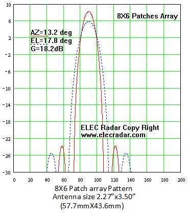
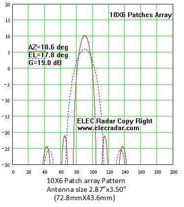
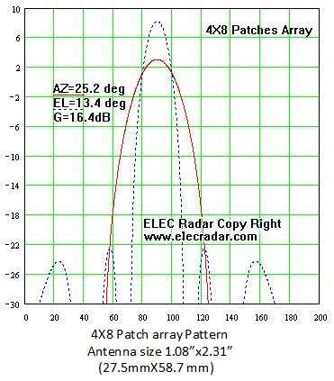
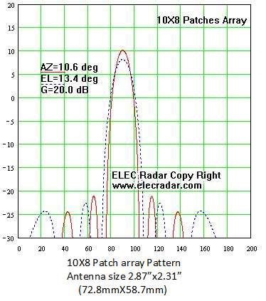
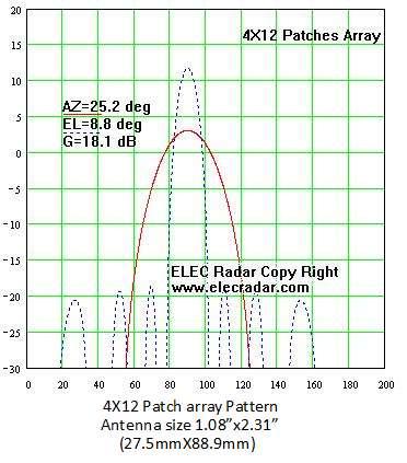
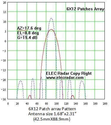
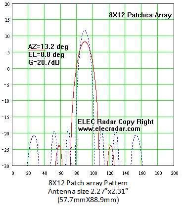
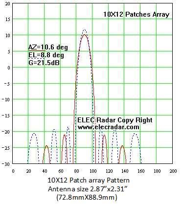
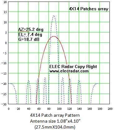
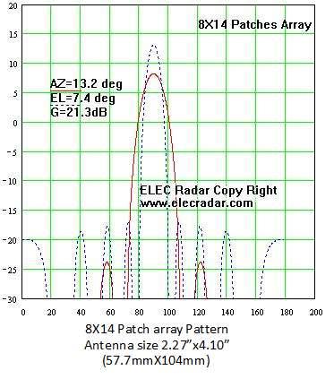
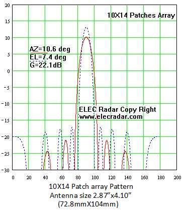
5 We will use GHz radar as example. Attached draw list patch number is 4, 6, 8, and 10 in azimuth-direction, and patch number is 6, 8, 10, 12, and 14 in elevation-direction. There are total 20 different antennas. Azimuth beam are 25.2(4patch), 17.6, 13.2, and 10.6 degree Elevation beam are 17.8(6 patch), 13.4, 10.6, 8.8, and 7.4 degree Antenna gain is from 15.5dB (4X6) to 22.1dB (10X14) One antenna size is from 1.08 X1.71 (27.5mmX43.4mm) for 4X8 patches to 2.86 X4.09 (72.6mmX104mm) for 10X14 patches Antenna spec outside our standard hardware is customer design. We only charge limit customer design cost for prototype. Another important fact is front-end size. For example, 4X8 patch array antenna has AZ beam 25.2 degree, EL beam 13.4 degree with 16.4dB gain. Antenna size is 1.08 X2.31. (27.5mmX 58.7mm) The front-end cross section size is different depend on design approaches. Most company design TX and RX share one antenna. Size maybe 1.3X 2.6 (need little larger than antenna size1.08 x2.31 ). This radar has no ability to detect AZ beam. And sensitivity is lower because leakage from TX to RX. ELEC Radar will use 2 antennas; no AZ beams detect ability, to improve sensitivity. But front-end size is increase to 2.4X2.6 ELEC Radar mono-pulse front-end need 3 antennas, size is increase to 3.5 X2.6. this front end has AZ beam detect ability (1 degree resolution from >22 degree coverage) If use 5 antennas to get 4-CH RX beam-forming front-end antenna, the size is increase to 5.7 X2.6. This front-end can detect multi targets even some of them in the same range. It is clear that even for 20 antennas listed in our attached table, there are 1, 2, 3, and 5 antennas for different function transceiver. Total is 80 selections. Since antenna is directly connected to backside TX or RX point, transceiver card design should change with antenna design. Page 5 of 11

6 Page 6 of 11


7 Page 7 of 11


8 Page 8 of 11


9 Page 9 of 11
10 Page 10 of 11

11 Page 11 of 11
1. The Part List of 24GHz Mono-Pulse FMCW Radar
 1. The Part List of 24GHz Mono-Pulse FMCW Radar 24GHz Mono-Pulse FMCW Radar Photo Basic Parts (All in 1 unit) Radar Front-end Radar Back-end DC Unit Cables 24GHz Mono-Pulse FMCW Front-End (3 or 5 antennas)
Scalable Front-End Digital Signal Processing for a Phased Array Radar Demonstrator. International Radar Symposium 2012 Warsaw, 24 May 2012
 Scalable Front-End Digital Signal Processing for a Phased Array Radar Demonstrator F. Winterstein, G. Sessler, M. Montagna, M. Mendijur, G. Dauron, PM. Besso International Radar Symposium 2012 Warsaw,
K-LC2 RADAR TRANSCEIVER
 Features 24 GHz K-band miniature I/Q transceiver 140MHz sweep FM input 2 x 4 patch antenna 2 balanced mixer with 50MHz bandwidth Excellent noise cancelling ability though I/Q technology Beam aperture 80
This article reports on
 Millimeter-Wave FMCW Radar Transceiver/Antenna for Automotive Applications A summary of the design and performance of a 77 GHz radar unit David D. Li, Sam C. Luo and Robert M. Knox Epsilon Lambda Electronics
PD Radar MTs and STs range and speed with sign 2 Triangle Wave FMCW MTs and STs range and speed with sign 2
 I. Background Continuous Wave (CW) radar is coherent radar system, which coupling part of TX power as RX LO. CW radar typical is used to detect target speed (without or with sign), range. They are popular
K-MC1 RADAR TRANSCEIVER. Features. Applications. Description. Blockdiagram. Datasheet
 Features 24 GHz short range transceiver 180 MHz sweep FM input High sensitivity, with integrated RF/IF amplifier Dual 30 patch antenna Buffered I/Q IF outputs Additional DC IF outputs Beam aperture 25
K-MC2 RADAR TRANSCEIVER Replaced by K-MC3 Datasheet. Features. Applications. Description. Blockdiagram
 Features 24 GHz short range transceiver 90MHz sweep FM input High sensitivity, integrated RF/IF amplifier Dual 62 patch narrow beam antenna Buffered, gain adjustable I/Q IF outputs Additional DC IF outputs
RSE02401/00 24 GHz Radar Sensor
 General description The RSE02401/00 is a fully integrated K-band FMCW radar sensor. It utilizes packaged low-cost components, enabling low unit prices and high volumes, using SMT assembly technology, with
K-MC4 MONOPULSE RADAR TRANSCEIVER. Features. Applications. Description. Blockdiagram. Datasheet
 Features 24 GHz short range monopulse transceiver Dual receiver +/- 15 angle coverage Beam aperture 30/ 12 @ -3 180MHz sweep FM input High sensitivity, integrated RF/IF amplifier Buffered I/Q IF outputs
Radio Frequency Electronics (RFE)
") Radio Frequency Electronics (RFE) by Prof. Dr.rer.nat. Dr.h.c. Manfred Thumm 5th Edition: 2011 Forschungszentrum Karlsruhe in der Helmholtz - Gemeinschaft Universität Karlsruhe (TH) Research University
Radio Frequency Electronics (RFE) by Prof. Dr.rer.nat. Dr.h.c. Manfred Thumm 5th Edition: 2011 Forschungszentrum Karlsruhe in der Helmholtz - Gemeinschaft Universität Karlsruhe (TH) Research University
RF and Microwave Test and Design Roadshow 5 Locations across Australia and New Zealand
 RF and Microwave Test and Design Roadshow 5 Locations across Australia and New Zealand ni.com Design and test of RADAR systems Agenda Radar Overview Tools Overview VSS LabVIEW PXI Design and Simulation
Effects to develop a high-performance millimeter-wave radar with RF CMOS technology
 Effects to develop a high-performance millimeter-wave radar with RF CMOS technology Yasuyoshi OKITA Kiyokazu SUGAI Kazuaki HAMADA Yoji OHASHI Tetsuo SEKI High Resolution Angle-widening Abstract We are
PERFORMANCE CONSIDERATIONS FOR PULSED ANTENNA MEASUREMENTS
 PERFORMANCE CONSIDERATIONS FOR PULSED ANTENNA MEASUREMENTS David S. Fooshe Nearfield Systems Inc., 19730 Magellan Drive Torrance, CA 90502 USA ABSTRACT Previous AMTA papers have discussed pulsed antenna
LOW COST PHASED ARRAY ANTENNA TRANSCEIVER FOR WPAN APPLICATIONS
 LOW COST PHASED ARRAY ANTENNA TRANSCEIVER FOR WPAN APPLICATIONS Introduction WPAN (Wireless Personal Area Network) transceivers are being designed to operate in the 60 GHz frequency band and will mainly
Advanced Digital Receiver
 Advanced Digital Receiver MI-750 FEATURES Industry leading performance with up to 4 M samples per second 135 db dynamic range and -150 dbm sensitivity Optimized timing for shortest overall test time Wide
mm-wave Transceiver Challenges for the 5G and 60GHz Standards Prof. Emanuel Cohen Technion
 mm-wave Transceiver Challenges for the 5G and 60GHz Standards Prof. Emanuel Cohen Technion November 11, 11, 2015 2015 1 mm-wave advantage Why is mm-wave interesting now? Available Spectrum 7 GHz of virtually
MOBILE RAPID-SCANNING X-BAND POLARIMETRIC (RaXPol) DOPPLER RADAR SYSTEM Andrew L. Pazmany 1 * and Howard B. Bluestein 2
 DOPPLER RADAR SYSTEM Andrew L. Pazmany 1 * and Howard B. Bluestein 2") 16B.2 MOBILE RAPID-SCANNING X-BAND POLARIMETRIC (RaXPol) DOPPLER RADAR SYSTEM Andrew L. Pazmany 1 * and Howard B. Bluestein 2 1 ProSensing Inc., Amherst, Massachusetts 2 University of Oklahoma, Norman,
16B.2 MOBILE RAPID-SCANNING X-BAND POLARIMETRIC (RaXPol) DOPPLER RADAR SYSTEM Andrew L. Pazmany 1 * and Howard B. Bluestein 2 1 ProSensing Inc., Amherst, Massachusetts 2 University of Oklahoma, Norman,
Frequently asked questions for 24 GHz industrial radar
 Frequently asked questions for 24 GHz industrial radar What is radar? Radar is an object-detection system that uses radio waves to determine the range, angle, or velocity of objects. A radar system consists
Doppler Simulator for 10 GHz Doppler Radar
 Doppler Simulator for 10 GHz Doppler Radar Presented by Ngeok Kuan Wai 2252462 Supervised by Prof. Dr.-Ing. K. Solbach Outline Motivation Doppler Radar and Doppler Simulator Phase shifter Other Electronic
Signal Processing and Display of LFMCW Radar on a Chip
 Signal Processing and Display of LFMCW Radar on a Chip Abstract The tremendous progress in embedded systems helped in the design and implementation of complex compact equipment. This progress may help
Using Frequency Diversity to Improve Measurement Speed Roger Dygert MI Technologies, 1125 Satellite Blvd., Suite 100 Suwanee, GA 30024
 Using Frequency Diversity to Improve Measurement Speed Roger Dygert MI Technologies, 1125 Satellite Blvd., Suite 1 Suwanee, GA 324 ABSTRACT Conventional antenna measurement systems use a multiplexer or
Wireless Communication Systems Laboratory Lab #3: Introduction to wireless front-end
 Objective Wireless Communication Systems Laboratory Lab #3: Introduction to wireless front-end The objective of this experiment is to study hardware components which are commonly used in most of the wireless
IQ+ XT. 144Mhz SDR-RF Exciter (preliminar v0.1)
") IQ+ XT 144Mhz SDR-RF Exciter (preliminar v0.1) INTRODUCTION Since the IQ+ receiver was introduced one year ago several people ask if I have plans to produce an IQ+ transmitter. Initially I didn't plan
IQ+ XT 144Mhz SDR-RF Exciter (preliminar v0.1) INTRODUCTION Since the IQ+ receiver was introduced one year ago several people ask if I have plans to produce an IQ+ transmitter. Initially I didn't plan
S-Band 2.4GHz FMCW Radar
 S-Band 2.4GHz FMCW Radar Iulian Rosu, YO3DAC / VA3IUL, Filip Rosu, YO3JMK, http://qsl.net/va3iul A Radar detects the presence of objects and locates their position in space by transmitting electromagnetic
Modeling & Simulating Antenna Arrays and RF Beamforming Algorithms Giorgia Zucchelli Product Marketing MathWorks
 Modeling & Simulating Antenna Arrays and RF Beamforming Algorithms Giorgia Zucchelli Product Marketing MathWorks giorgia.zucchelli@mathworks.nl 2016 The MathWorks, Inc. 1 Agenda Introducing antenna design
Project Report. Laptop Based Radar
 Project Report Laptop Based Radar Selected Topics in Microelectronics I (EE 680) (Spring Semester 2013) Submitted by: 1. Mirmehdi seyedesfahlan 2. Mohammad hossein Nemati 3. Efe Ozturk 4. Haq Nawaz 5.
The Old Cat and Mouse Game Continues
 The Old Cat and Mouse Game Continues or, How Advances in Radar Development Drive Testing Requirements for Next Generation EW Systems by: Walt Schulte Agilent Technologies Microwave and Communications Division
SYSTEM ARCHITECTURE OF RADAR NETWORK FOR MONITORING OF HAZARDOUD WEATHER
 SYSTEM ARCHITECTURE OF RADAR NETWORK FOR MONITORING OF HAZARDOUD WEATHER 2008. 11. 21 HOON LEE Gwangju Institute of Science and Technology &. CONTENTS 1. Backgrounds 2. Pulse Compression 3. Radar Network
Introduction. In the frequency domain, complex signals are separated into their frequency components, and the level at each frequency is displayed
 SPECTRUM ANALYZER Introduction A spectrum analyzer measures the amplitude of an input signal versus frequency within the full frequency range of the instrument The spectrum analyzer is to the frequency
Antenna Measurements using Modulated Signals
 Antenna Measurements using Modulated Signals Roger Dygert MI Technologies, 1125 Satellite Boulevard, Suite 100 Suwanee, GA 30024-4629 Abstract Antenna test engineers are faced with testing increasingly
Wireless Communication Systems Lab-Manual-3 Introduction to Wireless Front End. Objective
 Wireless Communication Systems Lab-Manual-3 Introduction to Wireless Front End Objective The objective of this experiment is to study hardware components which are commonly used in most of the wireless
Simulating and Testing of Signal Processing Methods for Frequency Stepped Chirp Radar
 Test & Measurement Simulating and Testing of Signal Processing Methods for Frequency Stepped Chirp Radar Modern radar systems serve a broad range of commercial, civil, scientific and military applications.
Multi Band Passive Forward Scatter Radar
 Multi Band Passive Forward Scatter Radar S. Hristov, A. De Luca, M. Gashinova, A. Stove, M. Cherniakov EESE, University of Birmingham Birmingham, B15 2TT, UK m.cherniakov@bham.ac.uk Outline Multi-Band
Ka Band Radar Transceiver
 Ka Band Radar Transceiver Ka-Band Radar Transceiver with Integrated LO Source Homodyne System with Integrated TX & LO Multiplied VCO with Phase noise
Design and Implementation of FMCW Radar Receiver in 65 nm CMOS Technology
 International Journal of Scientific and Research Publications, Volume 2, Issue 5, May 2012 1 Design and Implementation of FMCW Radar Receiver in 65 nm CMOS Technology Neha Agarwal*, Dwijendra Parashar**
Signal Forge 1800M Frequency Expansion Module. 1.0 GHz to 1.8 GHz. User Manual
 TM TM Signal Forge 1800M Frequency Expansion Module 1.0 GHz to 1.8 GHz User Manual Technical Support Email: Support@signalforge.com Phone: 512.275.3733 x2 Contact Information Web: www.signalforge.com
SPEC. Intelligent EW Systems for Complex Spectrum Operations ADEP. ADEP Product Descriptions
 Intelligent EW Systems for Complex Spectrum Operations ADEP TM Dynamic Engagement Products for Configurable Operational Response & Advanced Range Solutions ADEP Product Descriptions SPEC SPEC ADEP Overview
BYU SAR: A LOW COST COMPACT SYNTHETIC APERTURE RADAR
 BYU SAR: A LOW COST COMPACT SYNTHETIC APERTURE RADAR David G. Long, Bryan Jarrett, David V. Arnold, Jorge Cano ABSTRACT Synthetic Aperture Radar (SAR) systems are typically very complex and expensive.
RADIO RECEIVERS ECE 3103 WIRELESS COMMUNICATION SYSTEMS
 RADIO RECEIVERS ECE 3103 WIRELESS COMMUNICATION SYSTEMS FUNCTIONS OF A RADIO RECEIVER The main functions of a radio receiver are: 1. To intercept the RF signal by using the receiver antenna 2. Select the
Agilent Antenna and RCS Measurement Configurations Using PNA Microwave Network Analyzers. White Paper
 Agilent Antenna and RCS Measurement Configurations Using PNA Microwave Network Analyzers White Paper Abstract As technology changes, new and different techniques for measuring and characterizing antenna
Narrow Pulse Measurements on Vector Network Analyzers
 Narrow Pulse Measurements on Vector Network Analyzers Bert Schluper Nearfield Systems Inc. Torrance, CA, USA bschluper@nearfield.com Abstract - This paper investigates practical aspects of measuring antennas
Bistatic Radar Receiver for CubeSats: The RAX Payload
 Bistatic Radar Receiver for CubeSats: The RAX Payload John Buonocore Hasan Bahcivan SRI International 7 th Annual CubeSat Developer s Workshop 22 April 2010 Cal Poly San Luis Obispo SRI Proprietary RAX
Preliminary features of the SDR-X receiver SDR-X , PowerSDR Winrad Winrad DDS SFDR SFDR AD995 AD99 1
 Preliminary features of the SDR-X receiver The SDR-X receiver, in its full version is capable of continuously tuning the entire HF spectrum, 6m ( 50-52 MHz) band included. SSB, AM etc. demodulation, bandpass
Scalable Ionospheric Analyser SIA 24/6
 Scalable Ionospheric Analyser SIA 24/6 Technical Overview Functional description The ATRAD Scalable Ionospheric Analyser SIA24/6 is designed to observe ionospheric irregularities and their drift in the
Signal Forge 2500M Frequency Expansion Module. 1.5 GHz to 2.6 GHz. User Manual
 TM TM Signal Forge 2500M Frequency Expansion Module 1.5 GHz to 2.6 GHz User Manual Technical Support Email: Support@signalforge.com Phone: 512.275.3733 x2 Contact Information Web: www.signalforge.com Sales
5G Antenna System Characteristics and Integration in Mobile Devices Sub 6 GHz and Milli-meter Wave Design Issues
 5G Antenna System Characteristics and Integration in Mobile Devices Sub 6 GHz and Milli-meter Wave Design Issues November 2017 About Ethertronics Leader in advanced antenna system technology and products
Optical Delay Line Application Note
 1 Optical Delay Line Application Note 1.1 General Optical delay lines system (ODL), incorporates a high performance lasers such as DFBs, optical modulators for high operation frequencies, photodiodes,
Project: 3.8M Series 1385 Ku-Band Rx/Tx System. General Dynamics SATCOM Technologies
 Antenna Test Report Test No. 1761 Project: 3.8M Series 1385 Ku-Band Rx/Tx System. SATCOM Technologies East Maiden Antenna Test Facility 4488 Lawing Chapel Church Road Maiden, North Carolina 2865 828-428-1485
EITN90 Radar and Remote Sensing Lab 2
 EITN90 Radar and Remote Sensing Lab 2 February 8, 2018 1 Learning outcomes This lab demonstrates the basic operation of a frequency modulated continuous wave (FMCW) radar, capable of range and velocity
AIR ROUTE SURVEILLANCE 3D RADAR
 AIR TRAFFIC MANAGEMENT AIR ROUTE SURVEILLANCE 3D RADAR Supplying ATM systems around the world for more than 30 years indracompany.com ARSR-10D3 AIR ROUTE SURVEILLANCE 3D RADAR ARSR 3D & MSSR Antenna Medium
Pulsed S-Parameter Measurements using the ZVA network Analyzer
 Pulsed S-Parameter Measurements using the ZVA network Analyzer 1 Pulse Profile measurements ZVA Advanced Network Analyser 3 Motivation for Pulsed Measurements Typical Applications Avoid destruction of
Increasing Automotive Safety with 77/79 GHz Radar Solutions for ADAS Applications
 Increasing Automotive Safety with 77/79 GHz Radar Solutions for ADAS Applications FTF-AUT-F0086 Patrick Morgan Director, Safety Systems Business Unit Ralf Reuter Manager, Radar Applications and Systems
Evaluation of Millimeter wave Radar using Stepped Multiple Frequency Complementary Phase Code modulation
 Evaluation of Millimeter wave Radar using Stepped Multiple Frequency Complementary Phase Code modulation Masato WATANABE and Takayuki INABA Graduate School of Electro-Communications, The University of
DAMs Universal Link Commander
 Application Note #0428 May 2012 Revised: DAMs Universal Link Commander Application Note The Link Commander enables link analysis with or without DAMs measured data. It also enables range and Bit Error
Antenna and RCS Measurement Configurations Using Agilent s New PNA Network Analyzers
 Antenna and RCS Measurement Configurations Using Agilent s New PNA Network Analyzers John Swanstrom, Application Engineer, Agilent Technologies, Santa Rosa, CA Jim Puri, Applications Engineer, Agilent
High Gain Advanced GPS Receiver
 High Gain Advanced GPS Receiver NAVSYS Corporation 14960 Woodcarver Road, Colorado Springs, CO 80921 Introduction The NAVSYS High Gain Advanced GPS Receiver (HAGR) is a digital beam steering receiver designed
TestData Summary of 5.2GHz WLAN Direct Conversion RF Transceiver Board
 Page 1 of 16 ========================================================================================= TestData Summary of 5.2GHz WLAN Direct Conversion RF Transceiver Board =========================================================================================
Understanding Low Phase Noise Signals. Presented by: Riadh Said Agilent Technologies, Inc.
 Understanding Low Phase Noise Signals Presented by: Riadh Said Agilent Technologies, Inc. Introduction Instabilities in the frequency or phase of a signal are caused by a number of different effects. Each
Table of Contents. About SAGE Millimeter, Inc...1 Radar basics and related SAGE Millimeter microwave sensor technologies... 2
 A. INTRODUCTION About SAGE Millimeter, Inc.....1 Radar basics and related SAGE Millimeter microwave sensor technologies... 2 B. OSOCILLATORS (SOL Series) K band mechanically tuned Gunn oscillators......5
TEPZZ 9 77Z6A_T EP A1 (19) (11) EP A1 (12) EUROPEAN PATENT APPLICATION. (51) Int Cl.: G01S 7/35 ( )
 (11) EP A1 (12) EUROPEAN PATENT APPLICATION. (51) Int Cl.: G01S 7/35 ( )") (19) TEPZZ 9 77Z6A_T (11) EP 2 927 706 A1 (12) EUROPEAN PATENT APPLICATION (43) Date of publication: 07..1 Bulletin 1/41 (1) Int Cl.: G01S 7/3 (06.01) (21) Application number: 11901.4 (22) Date of filing:
(19) TEPZZ 9 77Z6A_T (11) EP 2 927 706 A1 (12) EUROPEAN PATENT APPLICATION (43) Date of publication: 07..1 Bulletin 1/41 (1) Int Cl.: G01S 7/3 (06.01) (21) Application number: 11901.4 (22) Date of filing:
DURIP Distributed SDR testbed for Collaborative Research. Wednesday, November 19, 14
 DURIP Distributed SDR testbed for Collaborative Research Distributed Software Defined Radar Testbed Collaborative research resource based on software defined radar (SDR) platforms that can adaptively modify
Using an Arbitrary Waveform Generator for Threat Generation
 Application Note - Using an Arbitrary Waveform Generator for Threat Generation Authors: Mark Elo, Giga-tronics & Christopher Loberg, Tektronix Published: August 1, 2015 Revision: A Introduction An arbitrary
Receiver Architecture
 Receiver Architecture Receiver basics Channel selection why not at RF? BPF first or LNA first? Direct digitization of RF signal Receiver architectures Sub-sampling receiver noise problem Heterodyne receiver
Radio with COTS Technologies. ATE Systems Engineer
 Signal Intelligence and Software-Defined Radio with COTS Technologies Sacha Emery ATE Systems Engineer 1 Agenda Introduction Optimised signal processing with multicore and FPGAs Timing and synchronisation
MSAN-001 X-Band Microwave Motion Sensor Module Application Note
 1. Introduction HB Series of microwave motion sensor modules are X-Band Mono-static DRO Doppler transceiver front-end module. These modules are designed for movement detection. They can be used in intruder
Space Frequency Coordination Group
 Space Frequency Coordination Group Report SFCG 38-1 POTENTIAL RFI TO EESS (ACTIVE) CLOUD PROFILE RADARS IN 94.0-94.1 GHZ FREQUENCY BAND FROM OTHER SERVICES Abstract This new SFCG report analyzes potential
60 GHz RX. Waveguide Receiver Module. Features. Applications. Data Sheet V60RXWG3. VubIQ, Inc
 GHz RX VRXWG Features Complete millimeter wave receiver WR-, UG-8/U flange Operates in the to GHz unlicensed band db noise figure Up to.8 GHz modulation bandwidth I/Q analog baseband interface Integrated
2015 The MathWorks, Inc. 1
 2015 The MathWorks, Inc. 1 What s Behind 5G Wireless Communications? 서기환과장 2015 The MathWorks, Inc. 2 Agenda 5G goals and requirements Modeling and simulating key 5G technologies Release 15: Enhanced Mobile
60 GHz Receiver (Rx) Waveguide Module
 Waveguide Module") The PEM is a highly integrated millimeter wave receiver that covers the GHz global unlicensed spectrum allocations packaged in a standard waveguide module. Receiver architecture is a double conversion,
The PEM is a highly integrated millimeter wave receiver that covers the GHz global unlicensed spectrum allocations packaged in a standard waveguide module. Receiver architecture is a double conversion,
G. Di Massa, S. Costanzo, F. Spadafora, A Raffo, A. Costanzo, L. Morrone, A. Borgia,
 Research Project INTEGRATED SYSTEMS FOR HYDROGEOLOGICAL RISK MONITORING, EARLY WARNING AND MITIGATION ALONG THE MAIN LIFELINES RADAR SYSTEMS FOR LANDSLIDES EARLY WARNING G. Di Massa, S. Costanzo, F. Spadafora,
Fundamentals of Arbitrary. Waveform Generation
 Fundamentals of Arbitrary Waveform Generation History Applications Key Specifications Optimization Signal fidelity and dynamic range Embedding and de-embedding Waveform generation and automation software
UMRR: A 24GHz Medium Range Radar Platform
 UMRR: A 24GHz Medium Range Radar Platorm Dr.-Ing. Ralph Mende, Managing Director smart microwave sensors GmbH Phone: +49 (531) 39023 0 / Fax: +49 (531) 39023 58 / ralph.mende@smartmicro.de Mittelweg 7
Modeling and Simulating Large Phased Array Systems
 Modeling and Simulating Large Phased Array Systems Tabrez Khan Senior Application Engineer Application Engineering Group 2015 The MathWorks, Inc. 1 Challenges with Large Array Systems Design & simulation
An Ultra Wideband Local Positioning System for Highly Complex Indoor Environments
 An Ultra Wideband Local Positioning System for Highly Complex Indoor Environments Benjamin Waldmann, Robert Weigel Institute for Electronics Engineering University of Erlangen Nuremberg Randolf Ebelt,
RF Board Design. EEC 134 Application Note. Jo Han Yu
 EEC 134 Application Note Jo Han Yu EEC 134 Application Note RF Board Design Introduction The objective of this application note is to outline the process of designing system and PCB layout for RF board
RF8889A SP10T ANTENNA SWITCH MODULE
 SP10T ANTENNA SWITCH MOD- ULE RF8889A SP10T ANTENNA SWITCH MODULE Package: QFN, 3.0mmx3.8mmx0.85mm GSM Rx1 RF8889A GSM Rx2 Features Broadband Performance Suitable for all Cellular Modulation Schemes up
77 GHz VCO for Car Radar Systems T625_VCO2_W Preliminary Data Sheet
 77 GHz VCO for Car Radar Systems Preliminary Data Sheet Operating Frequency: 76-77 GHz Tuning Range > 1 GHz Output matched to 50 Ω Application in Car Radar Systems ESD: Electrostatic discharge sensitive
Lecture Topics. Doppler CW Radar System, FM-CW Radar System, Moving Target Indication Radar System, and Pulsed Doppler Radar System
 Lecture Topics Doppler CW Radar System, FM-CW Radar System, Moving Target Indication Radar System, and Pulsed Doppler Radar System 1 Remember that: An EM wave is a function of both space and time e.g.
Lecture 6 SIGNAL PROCESSING. Radar Signal Processing Dr. Aamer Iqbal Bhatti. Dr. Aamer Iqbal Bhatti
 Lecture 6 SIGNAL PROCESSING Signal Reception Receiver Bandwidth Pulse Shape Power Relation Beam Width Pulse Repetition Frequency Antenna Gain Radar Cross Section of Target. Signal-to-noise ratio Receiver
What s Behind 5G Wireless Communications?
 What s Behind 5G Wireless Communications? Marc Barberis 2015 The MathWorks, Inc. 1 Agenda 5G goals and requirements Modeling and simulating key 5G technologies Release 15: Enhanced Mobile Broadband IoT
A Simple 122 GHz Transceiver
 A Simple 122 GHz Transceiver Using the Silicon Radar TRX120 Chip Mike Lavelle, K6ML BayCon 2018 Wait What??? Did he say 122 GHz? Yes, there are Ham bands above 2M BAND Freq. (GHz) 2 M 0.144-0.148 1.25
HF Receivers, Part 3
 HF Receivers, Part 3 Introduction to frequency synthesis; ancillary receiver functions Adam Farson VA7OJ View an excellent tutorial on receivers Another link to receiver principles NSARC HF Operators HF
76-81GHz MMIC transceiver (4 RX / 3 TX) for automotive radar applications. Table 1. Device summary. Order code Package Packing
 for automotive radar applications. Table 1. Device summary. Order code Package Packing") STRADA770 76-81GHz MMIC transceiver (4 RX / 3 TX) for automotive radar applications Data brief ESD protected Scalable architecture (master/slave configuration) BIST structures Bicmos9MW, 0.13-µm SiGe:C
STRADA770 76-81GHz MMIC transceiver (4 RX / 3 TX) for automotive radar applications Data brief ESD protected Scalable architecture (master/slave configuration) BIST structures Bicmos9MW, 0.13-µm SiGe:C
2006 Fynmeet Sea Clutter Measurement Trial
 26 Fynmeet Sea Clutter Measurement Trial Dataset Overview for 25-Jul-26 Dr PL Herselman 26 Fynmeet Sea Clutter Measurement Trial : Dataset Overview for 25-Jul-26 by Dr PL Herselman Published 6-Sep-27 15:7:13
PN9000 PULSED CARRIER MEASUREMENTS
 The specialist of Phase noise Measurements PN9000 PULSED CARRIER MEASUREMENTS Carrier frequency: 2.7 GHz - PRF: 5 khz Duty cycle: 1% Page 1 / 12 Introduction When measuring a pulse modulated signal the
EEC 134AB. Application Note. Radar System Design for RF. By: Yharo Torres. Group: Diode Hard 3. Fundamental Design of Radar:
 EEC 134AB Application Note Radar System Design for RF By: Yharo Torres Group: Diode Hard 3 Fundamental Design of Radar: The radar design we decided to go with for the quarter 2 design is one that is fundamentally
The Discussion of this exercise covers the following points:
 Exercise 3-2 Frequency-Modulated CW Radar EXERCISE OBJECTIVE When you have completed this exercise, you will be familiar with FM ranging using frequency-modulated continuous-wave (FM-CW) radar. DISCUSSION
An Introduction to Software Radio
 An Introduction to Software Radio (and a bit about GNU Radio & the USRP) Eric Blossom eb@comsec.com www.gnu.org/software/gnuradio comsec.com/wiki USENIX / Boston / June 3, 2006 What's Software Radio? It's
ADI 2006 RF Seminar. Chapter II RF/IF Components and Specifications for Receivers
 ADI 2006 RF Seminar Chapter II RF/IF Components and Specifications for Receivers 1 RF/IF Components and Specifications for Receivers Fixed Gain and Variable Gain Amplifiers IQ Demodulators Analog-to-Digital
Technician License Course Chapter 3 Types of Radios and Radio Circuits. Module 7
 Technician License Course Chapter 3 Types of Radios and Radio Circuits Module 7 Radio Block Diagrams Radio Circuits can be shown as functional blocks connected together. Knowing the description of common
A High-Resolution Survey of RFI at MHz as Seen By Argus
 A High-Resolution Survey of RFI at 1200-1470 MHz as Seen By Argus Steven W. Ellingson October 29, 2002 1 Summary This document reports on a survey of radio frequency interference (RFI) in the band 1200-1470
Demo / Application Guide for DSA815(-TG) / DSA1000 Series
 / DSA1000 Series") Demo / Application Guide for DSA815(-TG) / DSA1000 Series TX1000 Mobile Phone Frontend Mixer Bandpass Filter PA The schematic above shows a typical front end of a mobile phone. Our TX1000 RF Demo Kit shows
Demo / Application Guide for DSA815(-TG) / DSA1000 Series TX1000 Mobile Phone Frontend Mixer Bandpass Filter PA The schematic above shows a typical front end of a mobile phone. Our TX1000 RF Demo Kit shows
The Practical Limitations of S Parameter Measurements and the Impact on Time- Domain Simulations of High Speed Interconnects
 The Practical Limitations of S Parameter Measurements and the Impact on Time- Domain Simulations of High Speed Interconnects Dennis Poulin Anritsu Company Slide 1 Outline PSU Signal Integrity Symposium
MAKING TRANSIENT ANTENNA MEASUREMENTS
 MAKING TRANSIENT ANTENNA MEASUREMENTS Roger Dygert, Steven R. Nichols MI Technologies, 1125 Satellite Boulevard, Suite 100 Suwanee, GA 30024-4629 ABSTRACT In addition to steady state performance, antennas
Developing a Generic Software-Defined Radar Transmitter using GNU Radio
 Developing a Generic Software-Defined Radar Transmitter using GNU Radio A thesis submitted in partial fulfilment of the requirements for the degree of Master of Sciences (Defence Signal Information Processing)
RAYTHEON 23 x 22 50GHZ PULSE SYSTEM
 RAYTHEON 23 x 22 50GHZ PULSE SYSTEM Terry Speicher Nearfield Systems, Incorporated 1330 E. 223 rd Street, Bldg. 524 Carson, CA 90745 www.nearfield.com Angelo Puzella and Joseph K. Mulcahey Raytheon Electronic
X-Band QTRM Product Capability QTRM - Quad Transmit Receive Module (4-Channel T/R Module)
") MAIA-009446-000000 X-Band QTRM Product Capability QTRM - Quad Transmit Receive Module (4-Channel T/R Module) RS485 Half-Duplex, 5.0 Mbps serial data bus for control and monitoring. DSP externally programmable
MAIA-009446-000000 X-Band QTRM Product Capability QTRM - Quad Transmit Receive Module (4-Channel T/R Module) RS485 Half-Duplex, 5.0 Mbps serial data bus for control and monitoring. DSP externally programmable
Gain And Arbitrary Beamwidth Measurement For Identical Test Antennas
 Simple Antenna Measurements Using DAMs5.0 Advanced Software DESKTOP ANTENNA TEST SYSTEM Gain And Arbitrary Beamwidth Measurement For Identical Test Antennas This note demonstrates the measurement proceeder
The UMRR-S: A High-Performance 24GHz Multi Mode Automotive Radar Sensor for Comfort and Safety Applications
 The UMRR-S: A High-Perormance 24GHz Multi Mode Automotive Radar Sensor or Comort and Saety Applications Ralph Mende*, Marc Behrens*, Marc-Michael Meinecke**, Arne Bartels**, Thanh-Binh To** *smart microwave
Advanced RF Measurements You Didn t Know Your Oscilloscope Could Make. Brad Frieden Philip Gresock
 Advanced RF Measurements You Didn t Know Your Oscilloscope Could Make Brad Frieden Philip Gresock Agenda RF measurement challenges Oscilloscope platform overview Typical RF characteristics Bandwidth vs.