The Training Database is supplied as part of the RNS, and is loaded at the same time as the main program.
|
|
|
- Gregory Fields
- 5 years ago
- Views:
Transcription
1 THE TRAINING DATABASE The Training Database is supplied as part of the RNS, and is loaded at the same time as the main program. The Training Area is fictious, but the procedures are representative of the real world. The supplied area chart provides an immediately available environment in which radio navigation can take place. An exercise cross country radio navigation flight is included, which is made in nil wind conditions. However the flight profile may be re-run with wind if required. The non pilot or pilot under instructuin should refer to one of the many pilot training books, to obtain information on the techniques for flying and navigating with wind present. The Training Area chart shows the positions of all the facilities in the database. Distance and bearing measurements may be made on the chart, and the magnetic variation is 5 west over the whole area. A Chart Directory provides all the necessary information concerning the facilities.
2 The Cross Country Exercise The main purpose of this exercise is to expose to the pilot the main types of radio navigation facilities in the training environment, and to perform two NDB holds during the flight. With that objective, the selection of particular aids during the exercise may not necessarily be those which would be chosen during a normal flight. The cross country route commences overhead VOR/DME CCT and terminates with a NDB hold at ERY and is divided into four legs: Exercise Leg One Exercise Leg Two Exercise Leg Three Exercise Leg Four The distance is 245 nautical miles, and at a planned airspeed of 90 knots the flight duration will be about 3 hours, allowing time for the NDB holds.
3
4 Exercise Area Facilities List: Ident Facility Type Frequency Latitude Longitude Elevation CCT VOR/DME N E ft WIL VOR/DME N E ft SFG VOR/DME N E ft QLO VOR/DME N E ft DGH NDB(LOM) N E NMQ VOR/DME N E ft JIA NDB N E FFT VOR/DME N E ft HQL NDB N E GWR NDB N E JZX NDB N E AAP VOR N E AAP NDB N E NNR NDB N E LOR VOR/DME N E ft LOR NDB N E SPL VOR N E DLW NDB N E SSK VOR/DME N E ft JUS NDB N E LAU VOR N E UKM NDB N E DLX VOR/DME N E ft TTM NDB N E XDL VOR/DME N E ft DDU NDB N E BHK VOR/DME N E ft SLW VOR/DME N E ft WKP VOR N E STH VOR N E HWL VOR N E HWL NDB N E KQL VOR N E FFH NDB N E ERY NDB N E JEZ VOR/DME N E ft JEZ NDB N E XYS VOR/DME N E ft LSU VOR/DME N E ft VEK NDB(LOM) N E AIN VOR/DME N E ft CTK NDB(LOM) N E CTW NDB(LOM) N E
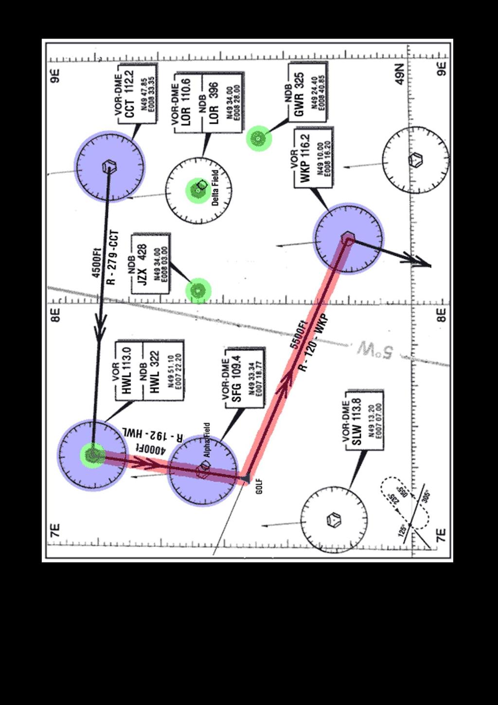
5 The Cross Country Exercise - Leg One Excercise Aims Leg l Primary: To fly the leg using the departure VOR/DME - CCT and the destination VOR/DME - HWL as the primary radio navigation aids. Secondary: During the passage of the flight to use the ADF to observe the bearings from adjacent NDB's - FFH - JZX - JIA HWL Flight Procedure Leg One: Start Position and Initial Navaids Selections: Position N E Overhead VOR/DME CCT Heading 279 Altitude Speed 4000ft 90kts NAV VOR CCT NAV VOR HWL DME NAV1 DME CCT ADF NDB JZX Select NAVl and set the 279 radial on the VOR indicator, if the OFF FLAG is displayed, the aircraft is still overhead the VOR/DME - CCT. Wait until FROM (FM) appears on the indicator, and alter heading to centre the VOR deviation needle as required. Maintain the 279 radial FROM VOR - CCT, until the DME range is 25nm, then select NAV2. The VOR indicator will now show a TO indication, since it is now selected to VOR - HWL. Adjust the heading to centre the deviation needle, and maintain the 279 radial until overhead VOR - HWL. When the OFF FLAG appears the aircraft will be very close to overhead VOR - HWL. At this point commence a RATE 1 turn to port, to rollout on 192 to start LEG 2. During the passage of the flight to use the ADF, first as an RBI, and then as an RMI, to observe the bearings from adjacent NDB's - JZX - FFH - JIA - HWL

6
7 The Cross Country Exercise - Leg Two Excercise Aims Leg Two Primary: To fly from overhead VOR/NDB - HWL on a designated radial, and to use an intercepted radial from VOR - WKP as a turning point, thereafter maintaining the intercepted radial until overhead VOR - WKP. Secondary: When flying the intercepted radial to VOR - WKP to observe the bearings from NDB's - JZX - HWL - VEK - ERY and to obtain a fix using multiple NDB bearings, using both RBI and RMI systems. Flight Procedure Leg Two: When the turn is complete descend to 4000 ft, and set the 192 Radial on the VOR indicator, which will now show a FROM (FM) indication. Centre the VOR deviation needle and maintain the 192 Radial from VOR - HWL. After passing overhead Alpha Field, tune NAVl to VOR - WKP, this will be used to provide a radial intercept, at the waypoint Golf Select NAVl and set the 120 radial on the VOR indicator, and observe that the deviation needle is left of centre, and that TO is displayed. Maintain the current heading and watch the deviation needle move slowly towards the centre of the indicator. When it reaches the centre the 120 radial will have been intercepted, and the aircraft will be positioned, at Waypoint GOLF, on the 120 radial TO the VOR - WKP. Execute a port RATE 1 turn onto the 120 radial. Continue to maintain the 120 radial until overhead VOR WKP. When the VOR indicator OFF FLAG appears, commence a starboard RATE 1 turn onto 203 to commence Leg 3.
8
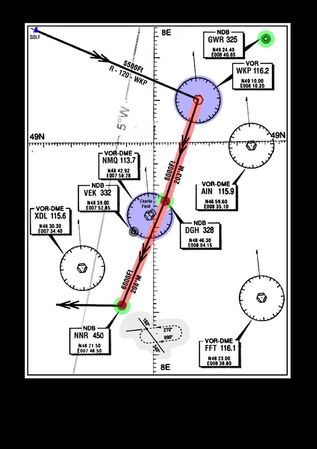
9 The Cross Country Exercise - Leg Three Excercise Aims Leg Three Prlmary: To fly from overhead VOR - WKP using the ADF, (In both RBI and RMI modes), as the primary navigation aid, homing first to NDB - DGH then to NDB - NNR. On arrival overhead NDB NNR, enter the holding pattern and complete two orbits. Secondary: Use the VOR - WKP, selected to radial 023 (TO), and observe the 'reversal' of the VOR deviation needle indications, when heading on the reciprocal of a selected radial. Deviate up to ten degrees port and starboard of the planned track to observe these effects. Regain the planned track before arriving overhead NDB - DGH. Practice radial intercepts from VOR - FFT and VOR - QLO whilst homing to NDB - NNR. Flight Procedure Leg Three: When the turn onto 203 is complete commence a climb to 6000 ft. Tune the ADF receiver to NDB - DGH, and observe the ADF relative bearing pointer, then observe the RMI magnetic bearings. Re-select the ADF RBI mode and Calculate the magnetic heading required to fly to NDB - DGH. (Add DI heading to ADF relative bearing to find the QDM (deduct 360 if the sum exeeded 360 ). Fly to overhead NDB - DGH using the ADF. When overhead NDB - DGH, retune the ADF receiver to NDB - NNR, and continue direct to NDB - NNR using the ADF. Check the excercise chart to confirm the orientation of the holding pattern for NDB - NNR. Using that information and the sector entry procedures for holding patterns, enter the hold when overhead NDB - NNR and complete two orbits. During the holds observe the aircraft track plot, when overhead the NDB - NNR, execute a RATE 1 turn right onto 275, to complete the final leg.
10
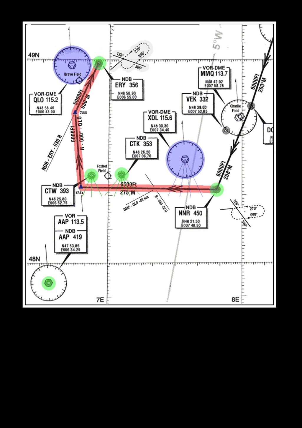
11 The Cross Country Exercise - Leg Four Excercise Aims Leg Four Primary: After completing the Hold on NDB - NNR to then depart NDB - NNR using the ADF as the primary navigation aid, using both RBI and RMI modes. Use VOR - QLO to provide two radial intercepts, the second intercept being the turning point. Thereafter to fly the intercepted radial until NDB - ERY bears 030 relative. Turn onto the NDB bearing and home to NDB - ERY using the ADF. Enter the Holding pattern at NDB - ERY and complete two orbits before terminating the excercise. Secondary: Use the ADF in RMI mode to observe its operation. Observe DME ranging from adjacent VOR/DME beacons Flight Procedure Leg Four: When the turn onto 275 is completed, climb to 6500ft. Select and tune NAV1 to VOR/DME - QLO. This VOR will be used to provide two radial intercepts, whilst maintaining NDB - NNR on 180 relative using the ADF in RBI mode. Set up the first intercept radial of 330 on the VOR indicator. The deviation needle will be to the right of centre and 'TO' will be indicated. This will be used as a VOR/DME intercept. Fly this leg using the ADF selected to NDB - NNR. Whilst in passage, set VOR/DME XDL on NAV2, and for practice, set the OBS intially to 340 and conduct several VOR radial intercepts approximately every 20 degrees of passage.( See Chart ). Observe the fairly constant DME range, and the false groundspeed from the DME, since the aircraft is not flying directly toward or away from XDL When the NAV1 VOR deviation needle reaches the centre of the indicator, the 330 TO radial will have been intercepted, observe that the DME range from VOR - QLO is approximately 49nms. (See Chart) Set up the next intercept radial of 000 on the NAV1 VOR indicator, the deviation needle will move to the left of the indicator, and the 'TO' flag will be displayed, and await the intercept. Whilst in passage use the ADF intially set to CTK followed by CTW, and using both RBI and RMI modes of operation, observe the bearing changes as the aircraft passes by both NDB's in turn. When the deviation needle nears the centre of the indicator, commence a rate 1 turn to starboard, at waypoint XRAY, onto the intercepted 000 radial, and descend to 5000ft. When the turn is complete, maintain the 000 radial to VOR - QLO. Tune the ADF receiver to NDB - ERY. When the ADF relative bearing approaches 030, and as a cross check, when the DME range to VOR/DME - QLO is 19 nms turn right, at waypoint ZULU, and home to NDB - ERY using the ADF. Check the Exercise area chart to confirm the orientation of the holding pattern for NDB - ERY. Using that information, and the sector entry procedures for holding patterns, enter the hold when on top NDB - ERY and complete two orbits before terminating the exercise. The format of the cross country excercise lends itself to be used as a basic route, from which deviations may be made to complete User choice activities.
12
13
Chapter 10 Navigation
 Chapter 10 Navigation Table of Contents VHF Omnidirectional Range (VOR) VOR Orientation Course Determination VOR Airways VOR Receiver Check Points Automatic Direction Finder (ADF) Global Positioning System
PERFORM A DME ARC. This document illustrates how to perform a DME arc with a HSI-equipped Beechcraft 90. Descent steps
 PERFORM A DME ARC 1. Introduction This document illustrates how to perform a DME arc with a HSI-equipped Beechcraft 90. 2. Preparatory work 2.1. Scenario You will need to open the following charts of Clermont
NAVIGATION INTRUMENTATION ADF
 1. Introduction NAVIGATION INTRUMENTATION ADF The Automatic Direction Finding (ADF) equipment on-board of aircraft is used together with the Non Directional Beacon (NDB) transmitters installed on the ground.
not authorized for IFR use. authorized for IFR use under VMC. authorized for IFR use under IMC until the runway is in sight.
 Gleim FAA Test Prep: Instrument Pilot (20 questions) Name: Date: Circle the correct answer on the question sheets AND fill in the corresponding circle on the separate answer sheet. [1] Gleim #: 3.4.32
NAVIGATION (2) RADIO NAVIGATION
 RADIO NAVIGATION") 1 An aircraft is "homing" to a radio beacon whilst maintaining a relative bearing of zero. If the magnetic heading decreases, the aircraft is experiencing: A left drift B right drift C a wind from the
1 An aircraft is "homing" to a radio beacon whilst maintaining a relative bearing of zero. If the magnetic heading decreases, the aircraft is experiencing: A left drift B right drift C a wind from the
NDB Approach Background
 NDB Approaches 1 NDB Approach Background One of the oldest and most disliked approaches Can use NDBs both on and off of the destination airport NDB approaches can be on the TO or FROM side of an NDB; some
Page K1. The Big Picture. Pilotage
 Page K1 Pilotage 1. [K1/3/2] Pilotage is navigation by A. reference to flight instruments. B. reference to landmarks. C. reference to airborne satellites. Electronic Elucidation The Big Picture 3. [K4/2/1]
INTERCEPT NDB TRACK. This documentation will present an example of NDB track interception performed with a Beechcraft BE90.
 1. Introduction INTERCEPT NDB TRACK This documentation will present an example of NDB track interception performed with a Beechcraft BE90. 2. Initial situation The initial situation is: 1. The aircraft
NAVIGATION INSTRUMENTS - BASICS
 NAVIGATION INSTRUMENTS - BASICS 1. Introduction Several radio-navigation instruments equip the different airplanes available in our flight simulators software. The type of instrument that can be found
How to Intercept a Radial Outbound
 How to Intercept a Radial Outbound by Greg Whiley Another practical publication from Aussie Star Flight Simulation How to intercepting a radial outbound 1 Greg Whiley Aussie Star Flight Simulation How
Navigation Systems - Enroute. Nolan, Chap 2
 Navigation Systems - Enroute Nolan, Chap 2 1 En-route Navigation Visual Flight Rules Instrument Flight Rules Pilotage/Dead-Reckoning Land-based Space-based Aircraft-based Aeronautic Charts Forecast Wind
Circle the correct answer on the question sheets and fill in the corresponding circle on the separate answer sheet.
 Gleim FAA Test Prep: Instrument Pilot (20 questions) IPGS Study Unit 3: Navigation Systems (IFH Ch 7, PHAK Ch 15) Name: Date: Circle the correct answer on the question sheets and fill in the corresponding
Navigation Systems. Chapter 7. Introduction. Ground Wave. Basic Radio Principles
 Chapter 7 Navigation Systems Introduction This chapter provides the basic radio principles applicable to navigation equipment, as well as an operational knowledge of how to use these systems in instrument
VOR/DME APPROACH WITH A320
 1. Introduction VOR/DME APPROACH WITH A320 This documentation presents an example of a VOR/DME approach performed with an Airbus 320 at LFRS runway 21. This type of approach is a non-precision approach
VOR = VHF Omni-directional Radio Range. Cockpit instrument. Navigation charts Different types. What comes to mind?
 VOR = VHF Omni-directional Radio Range What comes to mind? Cockpit instrument Navigation charts Different types 15-12-2009 VOR 1 VOR training BE V.2.1226 p1 FMC, does not come to mind, although it could
Fokker 50 - Automatic Flight Control System
 GENERAL The Automatic Flight Control System (AFCS) controls the aircraft around the pitch, roll, and yaw axes. The system consists of: Two Flight Directors (FD). Autopilot (AP). Flight Augmentation System
MGL Avionics. Odyssey/Voyager G2 and iefis
 MGL Avionics Odyssey/Voyager G2 and iefis Navigation This document applies to G2 version 1.1.0.1 or later, iefis 1.0.0.3 or later. Note: This document is based on the G2. The iefis system provides identical
Integrated Cockpit Display System ICDS 1000 Pilot Operation Handbook
 Integrated Cockpit Display System ICDS 1000 Pilot Operation Handbook ICDS1000 Pilot Operating Handbook Revision 1.3 572-0540 page 1 Table Of Contents Electronic Attitude Direction Indicator (EADI)... 8
This page is intentionally blank. GARMIN G1000 SYNTHETIC VISION AND PATHWAYS OPTION Rev 1 Page 2 of 27
 This page is intentionally blank. 190-00492-15 Rev 1 Page 2 of 27 Revision Number Page Number(s) LOG OF REVISIONS Description FAA Approved Date of Approval 1 All Initial Release See Page 1 See Page 1 190-00492-15
WARNING This operating manual has been writen to be used only with Microsoft Flight Simulator. FriendlyPanels
 FriendlyPanels Software WARNING This operating manual has been writen to be used only with Microsoft Flight Simulator. FriendlyPanels www.friendlypanels.net fpanels@friendlypanels.net 1. INTRODUCTION This
SD3-60 AIRCRAFT MAINTENANCE MANUAL - DESCRIPTION & OPERATION (PRE-MOD A8062) (1) Transceiver, Collins type DME40, (Part No.
 (1) Transceiver, Collins type DME40, (Part No.") AMM 53.0.0.0DME SYSTEM - DESCRIPTION & OPERATION (PRE-MOD A8062) 1. Description A. General Two identical D.M.E. systems are installed, one for each pilot. Frequency selection is made via each respective
AMM 53.0.0.0DME SYSTEM - DESCRIPTION & OPERATION (PRE-MOD A8062) 1. Description A. General Two identical D.M.E. systems are installed, one for each pilot. Frequency selection is made via each respective
Understanding VOR's, VORTAC's and How To Use Them
 Understanding VOR's, VORTAC's and How To Use Them by Hal Stoen Used by California Airlines (CAX) with permission from Hal Stoen 1998 first release: 2 December, 1998 INTRODUCTION The practical aspects of
Instrument Flight Procedures - Glass Cockpits
 Instrument Flight Procedures - Glass Cockpits The concepts contained here are general in nature and can be used by all however, they are targeted toward glass cockpits and, more specifically, integrated
AREA NAVIGATION SYSTEMS
 AREA NAVIGATION SYSTEMS 1. Introduction RNAV is defined as a method of navigation which permits aircraft operation on any desired flight path within the coverage of station-referenced navigation aids or
Apollo GPS Database Addendum
 Apollo GPS Database Addendum This document includes information that has been added to the waypoint database after the printing of the user s guide. A new waypoint type has been added to your database
MOONEY AIRCRAFT CORPORATION P. 0. Box 72 Kerrville, Texas FAA APPROVED
 P. 0. Box 72 Kerrville, Texas 78029 FAA APPROVED AIRPLANE FLIGHT MANUAL SUPPLEMENT FOR MOONEY M20J, M20K, M20L, M20M, M20R with Aircraft Serial No. Aircraft Reg. No. This supplement must be attached to
Basic GPS Operation. by Greg Whiley. Another practical publication from Aussie Star Flight Simulation
 Basic GPS Operation by Greg Whiley Another practical publication from Aussie Star Flight Simulation INTENTIONALLY LEFT BLANK Aussie Star Flight Simulation 2 Basic GPS Operations Statement of copyright
Navaid Substitution. Tuesday, March 24 th 3:40 p.m. 4:00 p.m.) PRESENTED BY: Jim Johnson, Honeywell Aerospace
 PRESENTED BY: Jim Johnson, Honeywell Aerospace") Tuesday, March 24 th 3:40 p.m. 4:00 p.m.) PRESENTED BY: Jim Johnson, Honeywell Aerospace International Operators Conference San Antonio, TX March 23 27, 2015 What is it? Navaid Substitution: Using a suitable
Tuesday, March 24 th 3:40 p.m. 4:00 p.m.) PRESENTED BY: Jim Johnson, Honeywell Aerospace International Operators Conference San Antonio, TX March 23 27, 2015 What is it? Navaid Substitution: Using a suitable
Navigation Equipment. Pilotage and Dead Reckoning. Navigational Aids. Radio Waves
 1 Navigation Equipment Successful air navigation not only involves piloting an aircraft from place to place, but also not getting lost, not breaking any FAA regulations, and not endangering the safety
VOR RADIALS VS MAGNETIC VARIATION
 VOR RADIALS VS MAGNETIC VARIATION FOR MISSION PILOTS MISSION CO-PILOTS AND MISSION OBSERVERS FOR CROSS TRACK FLIGHT PLAN CROSS TRACK SINGLE LEG AND GARMIN SAR METHODS 1 VOR radials do not always = current
FOUND FBA-2C1/2C2 BUSH HAWK EQUIPPED WITH SINGLE GARMIN GNS-430 # 1 VHF-AM COMM / VOR-ILS / GPS RECEIVER
 FOUND SUPPLEMENT M400-S11 Transport Canada Approved Flight Manual Supplement For FOUND BUSH HAWK EQUIPPED WITH SINGLE # 1 VHF-AM COMM / VOR-ILS / GPS RECEIVER Section 1 General is Unapproved and provided
AIRCRAFT AVIONIC SYSTEMS
 AIRCRAFT AVIONIC SYSTEMS B-777 cockpit Package C:\Documents and ettings\administrato Course Outline Radio wave propagation Aircraft Navigation Systems - Very High Omni-range (VOR) system - Instrument Landing
2 VHF DIRECTION FINDING
 2 VHF DIRECTION FINDING This chapter explains the principle of operation and the use of the VHF Ground Direction Finding (VDF). VDF provides means of determining the aircraft bearing from a ground station.
INSTALLATION MANUAL AND OPERATING INSTRUCTIONS
 INSTALLATION MANUAL AND OPERATING INSTRUCTIONS MD200-202/203/206/207 Series COURSE DEVIATION INDICATOR Mid-Continent Instruments and Avionics Manual Number 8017702 9400 E. 34 th Street N. Wichita, KS 67226
- FlightGear Autopilot and Route-Manager -
 - FlightGear 747-400 Autopilot and Route-Manager - General This documentation is valid for the version of 747-400 from 'buster' (http://flightgear.azuana.de). Our aircraft can be controlled by two different
Cockpit GPS Quick Start Guide
 Cockpit GPS Quick Start Guide Introduction My online book, Cockpit GPS, has grown to over 250 pages. I have that much information because at one time or another I thought that each piece would be useful
SAFETYSENSE LEAFLET 25 USE OF GPS
 SAFETYSENSE LEAFLET 25 USE OF GPS Most illustrations courtesy of Garmin UK and Honeywell 1. INTRODUCTION 2. SYSTEM AND SIGNAL ANOMALIES 3. EQUIPMENT 4. SYSTEM FAMILIARISATION 5. FLIGHT PLANNING 6. PROGRAMMING
INSTALLATION MANUAL AND OPERATING INSTRUCTIONS
 INSTALLATION MANUAL AND OPERATING INSTRUCTIONS MD200-302/303/306/307 Series COURSE DEVIATION INDICATOR MID-CONTINENT INST. CO., INC MANUAL NUMBER 8017972 Revisions Rev. Date Description of Change ECO#
Japan-US Aviation Environmental Workshop Fukutake Hall University of Tokyo 29 November 2017
 Japan-US Aviation Environmental Workshop Fukutake Hall University of Tokyo 29 November 2017 Keiichi Tamura All Nippon Airways B787 Technical Pilot, Dr. Eng. 2 Fundamentals of PBN (RNAV / RNP) Fundamentals
P/N 135A FAA Approved: 7/26/2005 Section 9 Initial Release Page 1 of 10
 FAA APPROVED AIRPLANE FLIGHT MANUAL SUPPLEMENT FOR GARMIN GNS 430 - VHF COMM/NAV/GPS Serial No: Registration No: When installing the Garmin GNS 430 - VHF COMM/NAV/GPS in the Liberty Aerospace XL2, this
MILITARY AERONAUTICAL INFORMATION PUBLICATION (M.A.I.P.) LOW ALTITUDE BALKANS THEATER - FALCON BMS 4.33
 LOW ALTITUDE BALKANS THEATER - FALCON BMS 4.33") MILITARY AERONAUTICAL INFORMATION PUBLICATION (M.A.I.P.) LOW ALTITUDE AIRPORT DIAGRAMS STANDARD INSTRUMENT DEPARTURES (SID) INSTRUMENT APPROACH PROCEDURES (IAP) BALKANS THEATER - FALCON BMS 4.33 Created
MILITARY AERONAUTICAL INFORMATION PUBLICATION (M.A.I.P.) LOW ALTITUDE AIRPORT DIAGRAMS STANDARD INSTRUMENT DEPARTURES (SID) INSTRUMENT APPROACH PROCEDURES (IAP) BALKANS THEATER - FALCON BMS 4.33 Created
APPENDIX C VISUAL AND NAVIGATIONAL AIDS
 VISUAL AND NAVIGATIONAL AIDS APPENDIX C VISUAL AND NAVIGATIONAL AIDS An integral part of the airport system is the visual and navigational aids provided to assist pilots in navigating both on the airfield
Table of Contents. Introduction 3. Pictorials of the 40 and 50 Systems 4. List of Applicable Acronyms 6
 Table of Contents Introduction 3 Pictorials of the 40 and 50 Systems 4 List of Applicable Acronyms 6 System 40 Modes of Operation 7 System 40 Functional Preflight Procedures 10 System 40 In Flight Procedures
Airfield Obstruction and Navigational Aid Surveys
 Section I. Section II. Section III. Section IV. Section V. Chapter 7 Airfield Obstruction and Navigational Aid Surveys The purpose of this chapter is to acquaint the Army surveyor with the terminologies
GNS 430 Basic Usage. VFR GPS Usage
 GNS 430 Basic Usage VFR GPS Usage Disclaimer This briefing is to designed to give an introductory overview so that as you read the GNS 430 Pilot s Guide and Reference you will have a basic understanding
MINIMUM EQUIPMENT LIST OPERATIONAL PROCEDURES ATA 34 NAVIGATION F100 ATA 34/ NAVIGATION CAA-01 ATA 34
 1 of 12 ATA 34/ NAVIGATION 2 of 12 11-1 Static ports Dispatch with ports at one side inoperative Take-off: With the static ports capped at one side, compensation for slip and crosswind conditions (take-off
Flight Management, Navigation Chapter 11
 Flight Management, Navigation Chapter 11 Controls and Indicators Section 10 11.10 Flight Management, Navigation-Controls and Indicators Flight Management System Control Display Unit (CDU) [Option Liquid
Tiny Flight Tracker & Viewer Manual
 Tiny Flight Tracker & Viewer Manual Version 3.xx Note: Program version number that appears in the pictures of this document may not reflect the latest available release. Tiny Flight Tracker & Viewer v3.xx
RADIO NAVIGATION
 details and associated Learning Objectives ATPL CPL ATPL/ ATPL CPL 062 00 00 00 RADIO NAVIGATION 062 01 00 00 BASIC RADIO PROPAGATION THEORY 062 01 01 00 Basic principles 062 01 01 01 Electromagnetic waves
CHANGE 1 CHAPTER FOUR - TACAN AND VOR NAVIGATION...
 CHANGE 1 CHAPTER FOUR - TACAN AND VOR NAVIGATION... 4-1 400. INTRODUCTION... 4-1 401. LESSON TOPIC LEARNING OBJECTIVES... 4-1 402. VOR - TACAN PROCEDURES AND OPERATING INSTRUCTIONS... 4-2 403. HOLDING...
Appendix B: Descriptions of Virtual Instruments (vis) Implemented
 Implemented") Appendix B: Descriptions of Virtual Instruments (vis) Implemented Overview of vis Implemented This appendix contains a brief description of each vi implemented in this project. Labview implements functions
Appendix B: Descriptions of Virtual Instruments (vis) Implemented Overview of vis Implemented This appendix contains a brief description of each vi implemented in this project. Labview implements functions
SD3-60 AIRCRAFT MAINTENANCE MANUAL
 AMM 24.0.0.0FLIGHT DIRECTOR SYSTEM - DESCRIPTION & OPERATION 1. Description A. General Refer to Figure 1. Identical, left and right, systems are installed (one for each pilot); each provides information
SAARBRÜCKEN Germany (EDDR)
") Hangars 1 2 For flight simulator use only. Not to be used for real world flight. 27 Germany () 27 Area of competency apron control Area of competency DFS TWR Terminal B 09 Noise abetement facility for
Hangars 1 2 For flight simulator use only. Not to be used for real world flight. 27 Germany () 27 Area of competency apron control Area of competency DFS TWR Terminal B 09 Noise abetement facility for
GRT Autopilot User Guide. All GRT EFIS Systems
 All GRT EFIS Systems Revision A 22-May-2014 Copyright 2014 3133 Madison Ave. SE Wyoming, MI 49548 (616) 245-7700 www.grtavionics.com Revision Notes Revision Date Change Description A 22-May-2014 Complete
The prior specification for navaid data was XP NAV810, which was compatible with X-Plane Changes in the spec for XP NAV1100 were:
 X-PLANE NAVIGATION DATA FOR NAVAIDS (USER_NAV.DAT & EARTH_NAV.DAT) FILE SPECIFICATION VERSION 1100 REVISION HISTORY 7 May 2009 Spec converted to this new format to support new web site (http://data.x-plane.com).
DOD/DFOISR CLEARANCE EXPORT NOTICE. Important Notice. Revision Highlights
 DOD/DFOISR CLEARANCE Cleared for Public Domain Release by the Office of Security Review, dated July 13, 2010, reference number 10-S-2457. EXPORT NOTICE This technical data has been released into the public
CHAPTER NAVIGATION SYSTEMS
 18--00--1 NAVIGATION SYSTEMS Table of Contents REV 3, May 03/05 CHAPTER 18 --- NAVIGATION SYSTEMS Page TABLE OF CONTENTS 18-00 Table of Contents 18--00--1 INTRODUCTION 18-10 Introduction 18--10--1 FLIGHT
Alsim Simulation Operating Instructions
 Alsim Simulation Operating Instructions Overview of Simulation This Alsim simulation is primarily designed to familiarize you with the avionics in the Alsim MCC200 Flight Simulator. The avionics and autopilot
491229N W DME I-DD. Freq-paired. Anemometer PAPI (3 ) MEHT 55. Fire Station. Hold. Twy E. Hold E Hold C2. Twy A (40) (62) Terminal Building
 MEHT 55. Fire Station. Hold. Twy E. Hold E Hold C2. Twy A (40) (62) Terminal Building") AERODROME CHART - ICAO ELEVATIONS IN FEET AMSL... HEIGHTS IN FEET ABOVE AD... (121) 491229N 0021144W 002 1230W 002 1200W 002 1130W ELEV 002 1100W (1 Sep 05) AD 2--2-1 491300N N 491300N 491230N 09 Displaced
AERODROME CHART - ICAO ELEVATIONS IN FEET AMSL... HEIGHTS IN FEET ABOVE AD... (121) 491229N 0021144W 002 1230W 002 1200W 002 1130W ELEV 002 1100W (1 Sep 05) AD 2--2-1 491300N N 491300N 491230N 09 Displaced
I3101 WORKSHEET. Prerequisites: -IN1203-4, IN1206-7, IN , and IN (Instruments CAI) -Q4390 (NATOPS check-ride)
 -Q4390 (NATOPS check-ride)") I3101 WORKSHEET Planned Route: Takeoff: KNPA, RWY 25R Altitude: 6000 Route: Radar departure from KNPA BFM (VOR holding) SQWID Approaches: KMOB VOR-A (arcing approach), KMOB RVFAC ILS RWY 15 KMOB RVFAC
I3101 WORKSHEET Planned Route: Takeoff: KNPA, RWY 25R Altitude: 6000 Route: Radar departure from KNPA BFM (VOR holding) SQWID Approaches: KMOB VOR-A (arcing approach), KMOB RVFAC ILS RWY 15 KMOB RVFAC
INSTALLATION MANUAL AND OPERATING INSTRUCTIONS
 INSTALLATION MANUAL AND OPERATING INSTRUCTIONS MD222-( ) SERIES TWO-INCH COURSE DEVIATION INDICATOR Mid-Continent Instruments and Avionics Manual Number 9016311 9400 E. 34 th Street N. Wichita, KS 67226
G1000 Integrated Flight Deck. Cockpit Reference Guide for the Cessna Citation Mustang
 G1000 Integrated Flight Deck Cockpit Reference Guide for the Cessna Citation Mustang FLIGHT INSTRUMENTS NAV/COM/TRANSPONDER/AUDIO PANEL AUTOMATIC FLIGHT CONTROL SYSTEM GPS NAVIGATION FLIGHT PLANNING PROCEDURES
Series III Avionics Pilot's Guide
 Chelton Avionics Inc. A Chelton Group Company 6400 Wilkinson Drive Prescott, AZ 86305 U.S.A. 150-041074 Rev. B i Wulfsberg Electronics Division, located in Prescott, Arizona, designs and manufactures the
STC FLIGHT FUNCTIONAL TEST
 GDC31 Roll Steering Converter 1049-2080-02 REV A 2004, DAC International All Rights Reserved. 6702 McNeil Drive Austin, Texas 78729 (512) 331-5323 Phone (512) 331-4516 Fax Page 1 of 14 Record of Revisions
Pilot s Guide KI 825. Bendix/King Safety Display System Electronic Horizontal Situation Indicator For Units Having -2, -3 and -4 Softwa re
 N Pilot s Guide KI 825 Bendix/King Safety Display System Electronic Horizontal Situation Indicator For Units Having -2, -3 and -4 Softwa re W A R N I N G The enclosed technical data is eligible for export
SN4500. Pilot s Guide. Primary Navigation Display. Reversionary Attitude Mode. with. (This page intentionally left blank)
") SN4500 Primary Navigation Display with Reversionary Attitude Mode (This page intentionally left blank) Pilot s Guide 82009-PG, REV D1 SANDEL SN4500 PILOT S GUIDE PAGE II Pilot information Publication Date:
SN4500 Primary Navigation Display with Reversionary Attitude Mode (This page intentionally left blank) Pilot s Guide 82009-PG, REV D1 SANDEL SN4500 PILOT S GUIDE PAGE II Pilot information Publication Date:
For Microsoft FSX and FS FriendlyPanels. All right reserved
 FriendlyPanels Software (version 2.0) For Microsoft FSX and FS9 2007 FriendlyPanels. All right reserved FOURTEEN GAUGES FOR YOUR FSX and FS9 AIRCRAFT 1 1. Introduction. 2. Requirements 3. Installing the
Annex II to ED Decision 2016/008/R K. SUBJECT 062 RADIO NAVIGATION. Syllabus details and associated Learning Objectives. Syllabus reference
 Syllabus 060 00 00 00 NAVIGATION ATPL CPL ATPL/ 062 00 00 00 RADIO NAVIGATION 062 01 00 00 BASIC RADIO PROPAGATION THEORY 062 01 01 00 Basic principles 062 01 01 01 Electromagnetic waves LO State that
ELITE Operator s Manual
 ELITE Jet v8 ELITE Operator s Manual The aircraft simulated by ELITE Jet represents the well known civil airliner MD-81. The instrumentation of the cockpit represents all standard instruments. Only the
GARMIN GNS430 Default Map Page
 GARMIN GNS430 Default Map Page Com Active/Standby Frequency Switch Toggle Switch Increase Frequency (MHz) Switch Power Button Nav Active/Standby Switch Ident Toggle Switch Com/Nav Set Switch Radio Frequency
Dash8 - Q400 - Autoflight
 12.3.1 Introduction The Automatic Flight Control System (AFCS), provides fail-safe operation of flight director guidance, autopilot, yaw damper and automatic pitch trim functions. 12.3.2 General The Automatic
2000 by UPS Aviation Technologies, Inc. All rights reserved. Printed in the U.S.A.
 No part of this document may be reproduced in any form or by any means without the express written consent of UPS Aviation Technologies, Inc. UPS Aviation Technologies, Inc., II Morrow, and Apollo are
DME I-GH & I-UY Freq-paired NDB GUY 361 ILS LLZ I-GH ILS LLZ I-UY PAPI (3 ) MEHT m x 45m Asphalt. TwyB Hold PAPI (3 ) MEHT 47
 MEHT m x 45m Asphalt. TwyB Hold PAPI (3 ) MEHT 47") AERODROME CHART - ICAO 002 3700W ELEVATIONS IN FEET AMSL... HEIGHTS IN FEET ABOVE AD... (51) 002 3630W 002 0W 002 3530W (12 May 05) AD 2--2-1 492606N 0027W ELEV 387 N 492630N 492630N 320 330 ILS LLZ I-GH
AERODROME CHART - ICAO 002 3700W ELEVATIONS IN FEET AMSL... HEIGHTS IN FEET ABOVE AD... (51) 002 3630W 002 0W 002 3530W (12 May 05) AD 2--2-1 492606N 0027W ELEV 387 N 492630N 492630N 320 330 ILS LLZ I-GH
SN3500 EHSI. Pilot s Guide Effectivity and Errata. Instructions
 SN3500 EHSI Pilot s Guide Effectivity and Errata Insert this update ahead of the cover page of the Pilot s Guide referenced below. Date: Effectivity: 05-OCT-2018 SN3500 Software Version 4.05, A4.08 Pilots
Exam questions: AE3-295-II
 Exam questions: AE3-295-II 1. NAVIGATION SYSTEMS (30 points) In this question we consider the DME radio beacon. [a] What does the acronym DME stand for? (3 points) DME stand for Distance Measuring Equipment
RJOM / MATSUYAMA AD CHART MATSUYAMA AP N M. AIP Japan MATSUYAMA RJOM-AD WIND DIRECTION INDICATOR LGT RWY 32 OVERRUN LGT APCH LGT BEACONS. 461.
 AIP Japan RJOM-AD2-24.1 RJOM / AD CHART AP 340m TWR 405m T S R Q P N M J K G H E F C D A B 8 9 10 11 12 13 ABN OVERRUN LGT PAPI Angle 3.0 MEHT 20m (66 ft) 190m WIND DIRECTION INDICATOR LGT 85m 1 2 3 5
OJAI AD 2.3 JORDAN 01 MAY 2008
 AIP AD 2.1 OJAI AD 2.1 AERODROME LOCATION INDICATOR AND NAME OJAI - Queen Alia International OJAI AD 2.2 AERODROME GEOGRAPHICAL AND ADMINISTRATIVE DATA 1 ARP coordinates and site at AD 313421.20480N 355935.57243E
AERONAUTICAL CHARTS. ordering is available at the National Aeronautical Charting Office (NACO) Web site:
 Web site:") This chapter provides an introduction to crosscountry flying under visual flight rules (VFR). It contains practical information for planning and executing cross-country flights for the beginning pilot.
This chapter provides an introduction to crosscountry flying under visual flight rules (VFR). It contains practical information for planning and executing cross-country flights for the beginning pilot.
AERONAUTICAL INFORMATION CIRCULAR 15/14
 AERONAUTICAL INFORMATION CIRCULAR 15/14 IMPLEMENTATION PLANNING OF CONTROLLER PILOT DATA LINK COMMUNICATIONS SERVICES IN CANADIAN DOMESTIC AIRSPACE Introduction (Replaces AIC 34/13) On 16 December 2011,
ENSTROM 480/480B OPERATOR S MANUAL AND FAA APPROVED ROTORCRAFT FLIGHT MANUAL SUPPLEMENT GARMIN GNS 430W/530W NAVIGATION SYSTEM
 ENSTROM 480/480B OPERATOR S MANUAL AND FAA APPROVED ROTORCRAFT FLIGHT MANUAL SUPPLEMENT GARMIN GNS 430W/530W NAVIGATION SYSTEM * * * * * REPORT NO. 28-AC-055 HELICOPTER SERIAL NO. HELICOPTER REGISTRATION
Learning Objectives 062 Radio Navigation
 Learning Objectives 062 Radio Navigation Syllabus 060 00 00 00 NAVIGATION 062 00 00 00 RADIO NAVIGATION 062 01 00 00 BASIC RADIO PROPAGATION THEORY 062 01 01 00 Basic principles 062 01 01 01 Electromagnetic
A-CR-CCP-803/PF-001 CHAPTER 14 PO 337 DEMONSTRATE AIR NAVIGATION SKILLS
 CHAPTER 14 PO 337 DEMONSTRATE AIR NAVIGATION SKILLS ROYAL CANADIAN AIR CADETS PROFICIENCY LEVEL THREE INSTRUCTIONAL GUIDE SECTION 1 EO M337.01 MEASURE DISTANCE ALONG A ROUTE Total Time: 30 min PREPARATION
Pilot s Guide KCS 55A. Bendix/King Compass System
 Pilot s Guide KCS 55A Bendix/King Compass System Introduction to the King KCS 55A Compass System... 3 Panel display: KI 525A Pictorial Navigation Indicator... 4 KA 516 Slaving Control and Compensator...
ICAO PBN GO TEAM PBN Implementation Workshop ENAC / ATM
 ICAO PBN GO TEAM PBN Implementation Workshop Minsk, BELARUS, 7-10 April 2015 ENAC / ATM Bertrand FOUCHER 1 PERSONAL BACKGROUND ATCO in Paris Charles de Gaulle ATC Supervisor in Paris Charles de Gaulle,
Chapter. Spaceship Earth (EAA)
") Chapter 9 Spaceship Earth (EAA) Navigation is the science of getting ships, aircraft or spacecraft from place to place... the method of determining position, course and distance traveled. This is what
Chapter 9 Spaceship Earth (EAA) Navigation is the science of getting ships, aircraft or spacecraft from place to place... the method of determining position, course and distance traveled. This is what
SN3308 Pilot s Guide. Effectivity and Errata
 SN3308 Pilot s Guide Effectivity and Errata Date: 4/15/2002 Revision: 2.10 pplies to: SN3308 Software 2.10 Pilot s Guide 82001PG-C 90106PG-C With the exception of the superseding information contained
Radio Navigation Stack. User Manual
 Radio Navigation Stack User Manual Table Of Contents Introduction Installation 2D Panel Configuration 3D (Virtual Cockpit) Use KMA 30 Audio Panel KX 165A Navigation/Communication Radio KX 165 Navigation/Communication
CONTENTS. INTRODUCTION 1 INTRODUCTION TO GPSPlus 3
 CONTENTS INTRODUCTION 1 INTRODUCTION TO GPSPlus 3 OPERATION OF GPSPlus 5 INTRODUCTION 6 SWITCHING ON 6 INITIAL DISPLAYS 6 USING THE LIGHTS KEY 7 NOTES ABOUT ENTERING DATA 7 USING THE POS KEY 8 USING WAYPOINTS
For Microsoft Flight Simulator FriendlyPanels. All right reserved. Table of Contents
 FriendlyPanels Software For Microsoft Flight Simulator 2004 2005 FriendlyPanels. All right reserved Table of Contents 1. Introduction 2. History 3. Specifications 4. Installation 5. Panel 6. Gauges 7.
NAVIGATION AND PITOT-STATIC SYSTEMS
 NAVIGATION AND PITOT-STATIC SYSTEMS. GENERAL This chapter describes the navigation systems, units, and components which provide airplane navigational information. Included are pitot-static, gyros, compass,
HORIZONTAL SITUATION INDICATOR [HSI]
![HORIZONTAL SITUATION INDICATOR [HSI]](/thumbs/86/93204935.jpg "HORIZONTAL SITUATION INDICATOR [HSI]") J. ' ~l l HORIZONTAL SITUATION INDICATOR [HSI] 1 l ~ 2
J. ' ~l l HORIZONTAL SITUATION INDICATOR [HSI] 1 l ~ 2
Database Coding and Publication
 MIXED MODE Database Coding and Publication Sorin-Dan Onitiu Jeppesen 17 October 2012 An inter-disciplinary overview of PBN design, coding and charting 1 Issue: Chart, Database, and Avionics Harmonization
SN3500 EHSI. Pilot s Guide Effectivity and Errata. (This page intentionally blank)
") SN3500 EHSI (This page intentionally blank) Pilot s Guide Effectivity and Errata Insert this update ahead of the cover page of the Pilot s Guide referenced below. Date: Effectivity: 03-JUL-2014 SN3500
SN3500 EHSI (This page intentionally blank) Pilot s Guide Effectivity and Errata Insert this update ahead of the cover page of the Pilot s Guide referenced below. Date: Effectivity: 03-JUL-2014 SN3500
Abacus CoPilot 3. AVSIM Commercial Utility Review. Product Information. Publisher: Abacus
 AVSIM Commercial Utility Review Abacus CoPilot 3 Publisher: Abacus Product Information Description: Flight Planner / Tracking Utility for FS2002 & FS2004 Download Size: 25.5MB or Boxed Format: Auto-install
Errata. 2. BFG WX-500 Stormscope : The following information is in addition to that presented in Chapter 3 of the Pilot s Guide:
 Errata 1. Northstar GPS/Loran: s of this date the Northstar GPS or Loran will only draw a courseline on the SN3308 when a flight plan is activated. courseline will not be drawn when using a direct-to.
FAA APPROVED AIRPLANE FLIGHT MANUAL SUPPLEMENT FOR. Trio Pro Pilot Autopilot
 Page 1 480 Ruddiman Drive TRIO AP Flight Manual Supplement North Muskegon, MI 49445 L-1006-01 Rev D FOR Trio Pro Pilot Autopilot ON Cessna 172, 175, 177, 180, 182, 185 and Piper PA28 Aircraft Document
KAP 140 Two Axis with Altitude Preselect Operation
 Two Axis/Altitude reselect Operations K 0 Two Axis with Altitude reselect Operation The K 0 is a digital, panel-mounted autopilot system for light aircraft. 7 8 K 0 D AV V AT D Two-axis w/altitude reelect
Mode 4A Unsafe terrain clearance with landing gear not down and flaps not in landing position
 1.6.18 Ground Proximity Warning System Allied Signal Aerospace (Honeywell) manufactures the GPWS, part number 965-0648- 008. The GPWS provides the following alerts if thresholds are exceeded: Mode 1 Excessive
Introduction to: Radio Navigational Aids
 Introduction to: Radio Navigational Aids 1 Lecture Topics Basic Principles Radio Directional Finding (RDF) Radio Beacons Distance Measuring Equipment (DME) Instrument Landing System (ILS) Microwave Landing
RJNK / KOMATSU AD CHART KOMATSU AD. AIP Japan KOMATSU RJNK-AD TWY C1 THRU C5. Installed on. Example for MANDATORY
 AIP Japan RJNK-AD2-24.1 RJNK / AD CHART AD TRUE NORTH APRON FLOOD LGT VORTAC () PAPI Angle 2.5 MEHT 20.0m(66ft) 570.86m CENTER-HELIPAD TAXIING GUIDANCE SIGNS 1 2 3 4 5 6 7 8 C-4 C-3 C-2 C-1 EAST-HELIPAD