AIRCRAFT AVIONIC SYSTEMS
|
|
|
- Juliana Randall
- 5 years ago
- Views:
Transcription
1 AIRCRAFT AVIONIC SYSTEMS
2 B-777 cockpit Package C:\Documents and ettings\administrato
3 Course Outline Radio wave propagation Aircraft Navigation Systems - Very High Omni-range (VOR) system - Instrument Landing System (ILS) - Distance Measuring Equipment (DME) - Weather Radar - Global Positioning System (GPS) Other systems
4 RADIO WAVE PROPAGATION


5 Radio waves Produced by electromagnetic energy Travel at straight lines with Speed of light (3x10 8 m/sec) cycle
6 Table of Radio Frequencies Band Abbreviation Frequency Wavelength Very Low Frequency VLF 3 KHz - 30 KHz 100,000m - 10,000m Low Frequency LF 30 KHz KHz 10,000m - 1,000 Medium Frequency MF 300 KHz - 3 MHz 1,000m - 100m High Frequency HF 3 MHz - 30 MHz 100m - 10m Very High Frequency VHF 30 MHz MHz 10m - 1m Ultra High Frequency UHF 300 MHz - 3 GHz 1m m Super High Frequency SHF 3 GHz - 30 GHz 0.10m m Extremely High Frequency EHF 30 GHz GHz 0.01m m
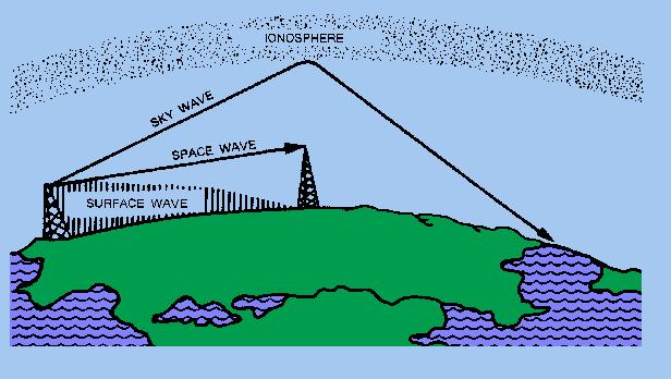
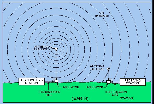
7 Radio wave transmission


8 Aircraft antennas Horizontal antenna Vertical antenna
9 B737 Antennas
10 NAVIGATION SYSTEMS
11 Navigation is the process of directing the movement of an aircraft from one point to another. Let s review some navigation terms. Navigation
12 Heading, track and course Heading : Direction airplane is pointed Track : Direction airplane is moving Course :It is intended direction of flight wind Heading Track

13 Latitude & Longitude Right now you are here Latitude N Longitude E 50 09
 navigation Position fixing")
14 Types of Navigation Two types of navigation are : Dead reckoning (DR) navigation Position fixing navigation
 necessary to safely get from point A to point B.")
15 Dead reckoning Dead reckoning is navigation method which requires continuous calculation of basic flight parameters (speed, time, etc) necessary to safely get from point A to point B. Heading & TAS Wind A Track & Grnd spd B
16 Dead Reckoning (DR) Navigation DR is independent of external navigational aids. Example : Inertial Navigation System (INS)
17 Position Fixing Navigation This navigation method is based on external aids (satellite or ground stations). Some examples: VHF omni-directional range (VOR) Automatic direction finders (ADF) Distance measuring equipment (DME) Instrument landing system (ILS) Global positioning system (GPS)
18 VHF OMNIRANGE (VOR) Navigation System

19 VOR system Provides position information through a series of ground stations. Its range is limited to line-of sight-distance
20 Segments of the VOR Complete VOR system consists of two segments : Ground stations Aircraft unit

.")
21 VOR ground stations Transmit VHF signals for navigation through 360 (omni-directional). Aligned with magnetic north
22 Navigation signals from VOR stations Magnetic North FROM 225 TO VOR FROM

23 Navigation signals from VOR stations

24 Aircraft VOR unit

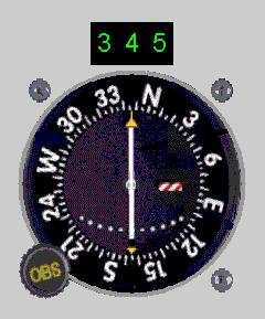
25 VOR indicator

26 VOR indications Station A B
27 VOR stations Navigation page

28 INSTRUMENT LANDING SYSTEM (ILS)
29 Components of ILS system ILS, is a system that helps flight crew for navigating to the runway under low visibility conditions. It Provides both lateral and vertical guidance to the pilot for touch down. It also aids larger aircraft (ex. Boeing 747,777) to land on a designated runway touchdown point. ILS system is composed of three components: - Localizer - Glide slope - Marker Beacon

30 ILS system components (Localizer & Glide slope)
31 Localizer The purpose of localizer is to provide horizontal position information to guide the pilot to the center of the runway. It consists of ground station and a receiver on the aircraft.


32 Localizer operation Ground transmitter/ Antenna Antenna Array RF Amplitude Modulated with 150 Hz RF Amplitude Modulated with 90 Hz
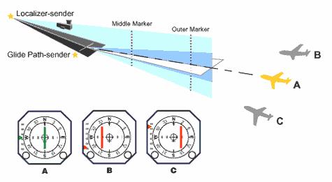
33 Localizer indication

34 Glide slope Glide slope provides vertical guidance to the pilot during the approach. It also consists of a transmitter on the ground and a receiver in the aircraft.

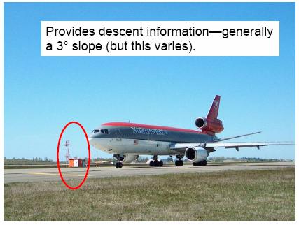
35 Glide slope ground transmitter

36 Glide slope operation Runway RF Amplitude Modulated with 90Hz RF Amplitude Modulated with 150Hz
37 Marker beacons The marker beacon is used to identify specific locations along the approach track. There are three marker beacons on the approach track to the runway - Outer marker (OM) - Middle marker (MM) - Inner marker (IM)


38 The Marker Beacon Ground transmitters Antenna
39 Marker beacons
40 Marker beacons Runway Inner marker grn. Trans. Middle marker grn. Trans. Outer marker grn. Trans.

41 ILS system
42 Distance Measuring Equipment (DME)
43 DME Basics It shows pilot a distance from a ground station (usually VOR station) in Nautical Miles (nm). Its range is limited to line of sight. DME stations are usually co-located with VOR stations (VOR/DME) The distance shown is slant range.
44 Slant Range Error increases as aircraft nears station Slant Range Ground Distance Station

45 DME operation Interrogation signal Replay signal Station

46 DME Antenna

47 WEATHER RADAR

48 Airborne radar functions (military)
49 Airborne radar functions (civil) Detection and avoidance thunderstorms Provide navigational support
50 Operation of radar Antenna Propagation Transmitted Pulse Return Reflected Pulse ( echo ) Target Cross Section
51 Operation of radar
52 Radar range measurement Transmitted Energy Reflected Energy Target Range Range = c t r / 2 t r = Round trip time c = speed of light (= 3x10 8 m/s = nm/s)

53 Beam width It is the angular width of the radar antenna beam. It is measured in degrees. Beam width


54 Examples of targets with low radar cross section
 antenna Narrower coverage, less signal loss, higher")
55 Radar Antennas Parabolic antenna Broader coverage, limited range Flat (Phased array) antenna Narrower coverage, less signal loss, higher range


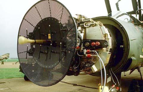
56 Radar Antennas Parabolic antenna Flat antenna
57 Weather Radar It provides pilot with the local picture of the weather ahead and allow him to avoid undesirable weather formations.
58 Weather radar
 HEAVY RAIN (INTENSE")
59 Order of reflectivity DRY CLOUDS (WEAK RETURNS) LIGHT RAIN (STRONGER RETURNS) HEAVY RAIN (INTENSE RETURNS)
60 Weather radar display
61 Weather Radar Display Extra Heavy rain Light rain medium rain Heavy rain
62 General safety rules in Radar Testing Ensure that no personnel are closer to a transmitting radar than maximum permissible exposure level (10mW/cm 2 ) Do not operate the radar when the aircraft is being refuelled or defuelled, Do not transmit when inflammable or explosive material are close to the aircraft. Do not operate close to large reflecting objects or in a hangar

63 Global Positioning System (GPS)
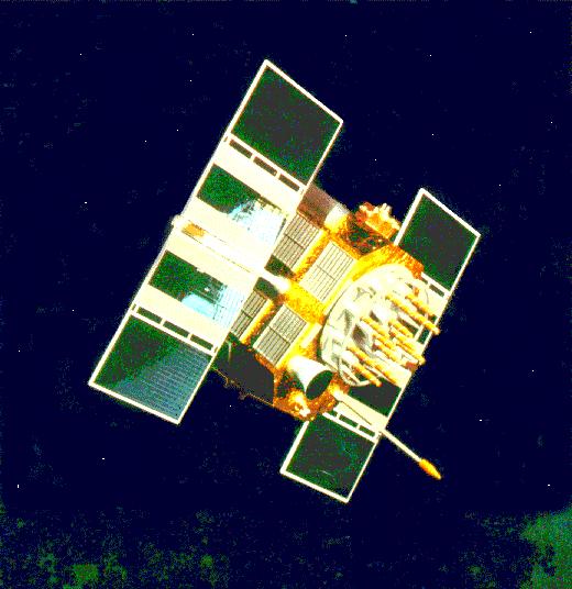
64 Global Positioning System (GPS) It is the latest technology that can be used for navigation GPS receives navigational inputs from space-based satellites It is very accurate and able to operate at any weather and geographical conditions since ground based navigational stations are not required for its operation
65 GPS Segments Space segment Control segment User segment

66 Space Segment
67 Space segments C:\Documents and ettings\administrato

68 Control Segment

69 User (Aircraft) segment Contains a GPS receiver. It receives the satellite signal and measure the time between the satellite transmission and receipt of the signal. The unit then calculates its current longitude, latitude and altitude. The receiver should see at least four satellite to compute three dimensional position.

70 GPS Operation

71 GPS antenna
72 GPS system
73 Inspections of avionic systems System inspections Antenna inspections Static discharge inspections Operational checks or any additional inspections required by the manufacturer
74 OTHER SYSTEMS
 Vertical Speed Indicator (VSI) Altimeter Gyroscopic Instruments Attitude Indicator Heading")
75 Flight Instruments These instruments allow pilot to visualize the attitude and location of the aircraft. Pitot-Static System and Instruments Airspeed Indicator (ASI) Vertical Speed Indicator (VSI) Altimeter Gyroscopic Instruments Attitude Indicator Heading Indicator Turn Coordinator Magnetic Magnetic Compass
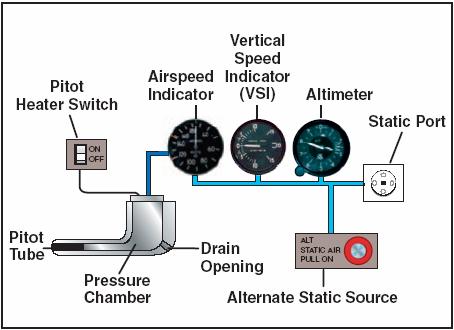
76 Pitot-static system

77 Pitot tube Pitot tube

78 Static ports

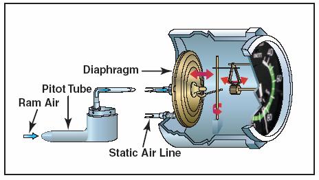
79 Airspeed indicator (ASI)

")
80 Vertical Speed Indicator (VSI)
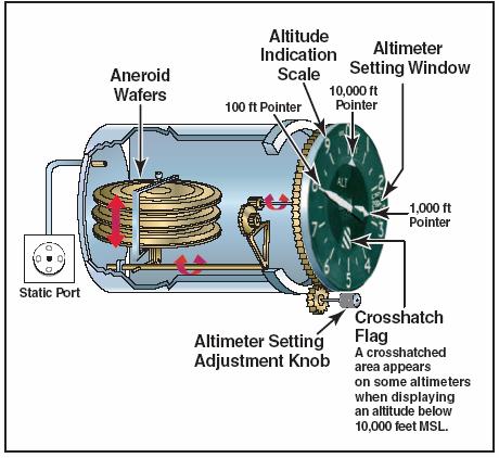
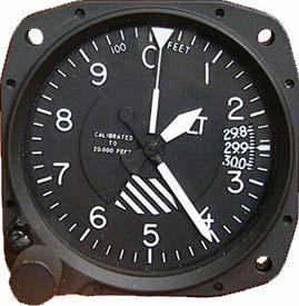
81 Altimeter

82 Some instruments Altimeter Airspeed/Mach Indicator VSI
83 Pitot-static System malfunctions Instrument Static line Blockage Pitot line Blockage Altimeter "Freezes" at constant value n/a Vertical Speed Indicator "Freezes" at zero n/a Airspeed Indicator Under-reads in climb and over-reads in descent Over-reads in climb and under-reads in descent
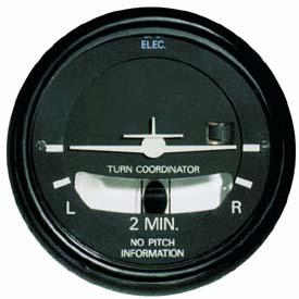
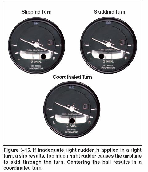
84 Turn coordinator


85 Attitude and heading indicators Attitude indicator Heading indicator
86 Attitude indicator C:\Documents and ettings\administrato
87 Turn coordinator C:\Documents and ettings\administrato
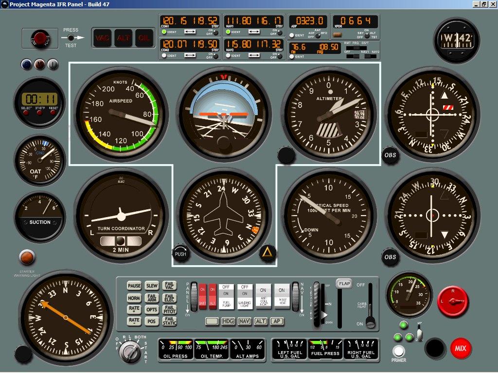
88 Various instruments
 Primary Flight")

89 Electronic flight instrument system (EFIS) Primary Flight Display MFD or Navigation Display Engine Displays And crew alert system

90 Head-up Display (HUD)

91 Head-up Display (HUD)

92 Flight Management System (FMS)

93 FMS Control & Display Unit
 (4 in. x 5 in.")
 (5 in. x 5 in.) Multipurpose color display (15.2 cm x 15.2 cm) (6 in. x 6 in.")
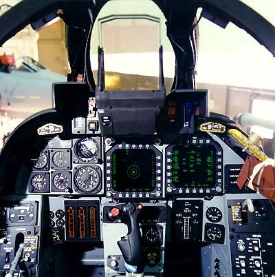
94 Advanced Fighter Cockpit Head-up display (20 field-of-view) Up-front control/display Touch-sensitive LCD (10.2 cm x 12.7 cm) (4 in. x 5 in.) Engine/fuel display HOTAS controls Joint helmet mounted cueing system Multifunction color displays (12.7 cm x 12.7 cm) (5 in. x 5 in.) Multipurpose color display (15.2 cm x 15.2 cm) (6 in. x 6 in.) Nigh-vision compatible Easy to fly optimized for minimum pilot workload
95 THANK YOU
NAVIGATION INSTRUMENTS - BASICS
 NAVIGATION INSTRUMENTS - BASICS 1. Introduction Several radio-navigation instruments equip the different airplanes available in our flight simulators software. The type of instrument that can be found
NAVIGATION (2) RADIO NAVIGATION
 RADIO NAVIGATION") 1 An aircraft is "homing" to a radio beacon whilst maintaining a relative bearing of zero. If the magnetic heading decreases, the aircraft is experiencing: A left drift B right drift C a wind from the
1 An aircraft is "homing" to a radio beacon whilst maintaining a relative bearing of zero. If the magnetic heading decreases, the aircraft is experiencing: A left drift B right drift C a wind from the
EE Chapter 14 Communication and Navigation Systems
 EE 2145230 Chapter 14 Communication and Navigation Systems Two way radio communication with air traffic controllers and tower operators is necessary. Aviation electronics or avionics: Avionic systems cover
Communication and Navigation Systems for Aviation
 Higher National Unit Specification General information for centres Unit title: Communication and Navigation Systems for Aviation Unit code: F0M3 35 Unit purpose: This Unit is designed to allow candidates
Exam questions: AE3-295-II
 Exam questions: AE3-295-II 1. NAVIGATION SYSTEMS (30 points) In this question we consider the DME radio beacon. [a] What does the acronym DME stand for? (3 points) DME stand for Distance Measuring Equipment
Introduction to: Radio Navigational Aids
 Introduction to: Radio Navigational Aids 1 Lecture Topics Basic Principles Radio Directional Finding (RDF) Radio Beacons Distance Measuring Equipment (DME) Instrument Landing System (ILS) Microwave Landing
Learning Objectives 062 Radio Navigation
 Learning Objectives 062 Radio Navigation Syllabus 060 00 00 00 NAVIGATION 062 00 00 00 RADIO NAVIGATION 062 01 00 00 BASIC RADIO PROPAGATION THEORY 062 01 01 00 Basic principles 062 01 01 01 Electromagnetic
NAVIGATION INTRUMENTATION ADF
 1. Introduction NAVIGATION INTRUMENTATION ADF The Automatic Direction Finding (ADF) equipment on-board of aircraft is used together with the Non Directional Beacon (NDB) transmitters installed on the ground.
Agilent 8644A-2 Air Navigation Receiver Testing with the Agilent 8644A
 Agilent 8644A-2 Air Navigation Receiver Testing with the Agilent 8644A Application Note This application note describes the synthesized internal audio source used in the Agilent Technologies 8645A, 8665A,
Satellite Navigation (and positioning)
") Satellite Navigation (and positioning) Picture: ESA AE4E08 Instructors: Sandra Verhagen, Hans van der Marel, Christian Tiberius Course 2010 2011, lecture 1 Today s topics Course organisation Course contents
Satellite Navigation (and positioning) Picture: ESA AE4E08 Instructors: Sandra Verhagen, Hans van der Marel, Christian Tiberius Course 2010 2011, lecture 1 Today s topics Course organisation Course contents
Chapter 10 Navigation
 Chapter 10 Navigation Table of Contents VHF Omnidirectional Range (VOR) VOR Orientation Course Determination VOR Airways VOR Receiver Check Points Automatic Direction Finder (ADF) Global Positioning System
RADIO NAVIGATION
 details and associated Learning Objectives ATPL CPL ATPL/ ATPL CPL 062 00 00 00 RADIO NAVIGATION 062 01 00 00 BASIC RADIO PROPAGATION THEORY 062 01 01 00 Basic principles 062 01 01 01 Electromagnetic waves
Annex II to ED Decision 2016/008/R K. SUBJECT 062 RADIO NAVIGATION. Syllabus details and associated Learning Objectives. Syllabus reference
 Syllabus 060 00 00 00 NAVIGATION ATPL CPL ATPL/ 062 00 00 00 RADIO NAVIGATION 062 01 00 00 BASIC RADIO PROPAGATION THEORY 062 01 01 00 Basic principles 062 01 01 01 Electromagnetic waves LO State that
AE4-393: Avionics Exam Solutions
 AE4-393: Avionics Exam Solutions 2008-01-30 1. AVIONICS GENERAL a) WAAS: Wide Area Augmentation System: an air navigation aid developed by the Federal Aviation Administration to augment the Global Positioning
APPENDIX C VISUAL AND NAVIGATIONAL AIDS
 VISUAL AND NAVIGATIONAL AIDS APPENDIX C VISUAL AND NAVIGATIONAL AIDS An integral part of the airport system is the visual and navigational aids provided to assist pilots in navigating both on the airfield
Technician License Course Chapter 2 Radio and Signals Fundamentals
 Technician License Course Chapter 2 Radio and Signals Fundamentals Handling Large and Small Numbers Electronics and Radio use a large range of sizes, i.e., 0.000000000001 to 1000000000000. Scientific Notation
NAVIGATION AND PITOT-STATIC SYSTEMS
 NAVIGATION AND PITOT-STATIC SYSTEMS. GENERAL This chapter describes the navigation systems, units, and components which provide airplane navigational information. Included are pitot-static, gyros, compass,
10 Secondary Surveillance Radar
 10 Secondary Surveillance Radar As we have just noted, the primary radar element of the ATC Surveillance Radar System provides detection of suitable targets with good accuracy in bearing and range measurement
TITLE 14 OF THE CODE OF FEDERAL REGULATIONS (14 CFR) GUIDANCE MATERIAL
 GUIDANCE MATERIAL") TITLE 14 OF THE CODE OF FEDERAL REGULATIONS (14 CFR) GUIDANCE MATERIAL Subject: INDEX OF AVIATION TECHNICAL STANDARD ORDERS Date: 10/10/00 Initiated by: AIR-120 AC No: AC 20-110L Change: 1. PURPOSE. This
TITLE 14 OF THE CODE OF FEDERAL REGULATIONS (14 CFR) GUIDANCE MATERIAL Subject: INDEX OF AVIATION TECHNICAL STANDARD ORDERS Date: 10/10/00 Initiated by: AIR-120 AC No: AC 20-110L Change: 1. PURPOSE. This
Page K1. The Big Picture. Pilotage
 Page K1 Pilotage 1. [K1/3/2] Pilotage is navigation by A. reference to flight instruments. B. reference to landmarks. C. reference to airborne satellites. Electronic Elucidation The Big Picture 3. [K4/2/1]
Keysight Technologies VOR and ILS Radio Navigation Receiver Test Using Option 302 for Keysight Signal Sources. Application Note
 Keysight Technologies VOR and ILS Radio Navigation Receiver Test Using Option 302 for Keysight Signal Sources Application Note Introduction The Keysight X-series (EXG and MXG) analog and vector signal
WRC19 Preparatory Workshop
 ICAO Doc 9718 Handbook on Radio Frequency Spectrum Requirements for Civil Aviation Vol. I - ICAO Spectrum Strategy Vol. II - Frequency Planning 100 khz 200 khz 300 khz 400 khz 600 khz 800 khz 1 MHz 2 MHz
ICAO Handbook on Radio Frequency Spectrum Requirements for Civil Aviation Vol. I - ICAO Spectrum Strategy Vol. II - Frequency Planning
 ICAO Handbook on Radio Frequency Spectrum Requirements for Civil Aviation Vol. I - ICAO Spectrum Strategy Vol. II - Frequency Planning 100 khz 200 khz 300 khz 400 khz 600 khz 800 khz 1 MHz 2 MHz 3 MHz
Copyrighted Material - Taylor & Francis
 22 Traffic Alert and Collision Avoidance System II (TCAS II) Steve Henely Rockwell Collins 22. Introduction...22-22.2 Components...22-2 22.3 Surveillance...22-3 22. Protected Airspace...22-3 22. Collision
Antenna & Propagation. Basic Radio Wave Propagation
 For updated version, please click on http://ocw.ump.edu.my Antenna & Propagation Basic Radio Wave Propagation by Nor Hadzfizah Binti Mohd Radi Faculty of Electric & Electronics Engineering hadzfizah@ump.edu.my
Radio Communication. Presentation created by: András Balogh
 Radio Communication Presentation created by: András Balogh AM and FM The goal is to transmit a modulating signal S(t) via a wave sin(ωt). In case of AM, the product of the modulation is f(t)=(a+s(t))*sin(ωt);
Engineering. Aim. Unit abstract. QCF level: 6 Credit value: 15
 Unit T22: Avionic Systems Engineering Unit code: R/504/0134 QCF level: 6 Credit value: 15 Aim The aim of this unit is to provide learners with a detailed knowledge and understanding of a wide range of
Radar Reprinted from "Waves in Motion", McGourty and Rideout, RET 2005
 Radar Reprinted from "Waves in Motion", McGourty and Rideout, RET 2005 What is Radar? RADAR (Radio Detection And Ranging) is a way to detect and study far off targets by transmitting a radio pulse in the
VOR/DME APPROACH WITH A320
 1. Introduction VOR/DME APPROACH WITH A320 This documentation presents an example of a VOR/DME approach performed with an Airbus 320 at LFRS runway 21. This type of approach is a non-precision approach
Radar observables: Target range Target angles (azimuth & elevation) Target size (radar cross section) Target speed (Doppler) Target features (imaging)
 Target size (radar cross section) Target speed (Doppler) Target features (imaging)") Fundamentals of Radar Prof. N.V.S.N. Sarma Outline 1. Definition and Principles of radar 2. Radar Frequencies 3. Radar Types and Applications 4. Radar Operation 5. Radar modes What What is is Radar? Radar?
Fundamentals of Radar Prof. N.V.S.N. Sarma Outline 1. Definition and Principles of radar 2. Radar Frequencies 3. Radar Types and Applications 4. Radar Operation 5. Radar modes What What is is Radar? Radar?
Data and Computer Communications Chapter 4 Transmission Media
 Data and Computer Communications Chapter 4 Transmission Media Ninth Edition by William Stallings Data and Computer Communications, Ninth Edition by William Stallings, (c) Pearson Education - Prentice Hall,
A bluffer s guide to Radar
 A bluffer s guide to Radar Andy French December 2009 We may produce at will, from a sending station, an electrical effect in any particular region of the globe; (with which) we may determine the relative
PRINCIPLES OF COMMUNICATION SYSTEMS. Lecture 1- Introduction Elements, Modulation, Demodulation, Frequency Spectrum
 PRINCIPLES OF COMMUNICATION SYSTEMS Lecture 1- Introduction Elements, Modulation, Demodulation, Frequency Spectrum Topic covered Introduction to subject Elements of Communication system Modulation General
F-104 Electronic Systems
 Information regarding the Lockheed F-104 Starfighter F-104 Electronic Systems An article published in the Zipper Magazine # 49 March-2002 Author: Country: Website: Email: Theo N.M.M. Stoelinga The Netherlands
Fundamentals of HF Data Link
 Fundamentals of HF Data Link 2014 Rockwell 2014 Collins. Rockwell Collins. Framework for Discussion General Overview Propagation The Ground Component Architecture HFDL Ground Station The Airborne Component
RADAR CHAPTER 3 RADAR
 RADAR CHAPTER 3 RADAR RDF becomes Radar 1. As World War II approached, scientists and the military were keen to find a method of detecting aircraft outside the normal range of eyes and ears. They found
Helicopter Aerial Laser Ranging
 Helicopter Aerial Laser Ranging Håkan Sterner TopEye AB P.O.Box 1017, SE-551 11 Jönköping, Sweden 1 Introduction Measuring distances with light has been used for terrestrial surveys since the fifties.
Keywords. DECCA, OMEGA, VOR, INS, Integrated systems
 Keywords. DECCA, OMEGA, VOR, INS, Integrated systems 7.4 DECCA Decca is also a position-fixing hyperbolic navigation system which uses continuous waves and phase measurements to determine hyperbolic lines-of
This page is intentionally blank. GARMIN G1000 SYNTHETIC VISION AND PATHWAYS OPTION Rev 1 Page 2 of 27
 This page is intentionally blank. 190-00492-15 Rev 1 Page 2 of 27 Revision Number Page Number(s) LOG OF REVISIONS Description FAA Approved Date of Approval 1 All Initial Release See Page 1 See Page 1 190-00492-15
Scientific Journal of Silesian University of Technology. Series Transport Zeszyty Naukowe Politechniki Śląskiej. Seria Transport
 Scientific Journal of Silesian University of Technology. Series Transport Zeszyty Naukowe Politechniki Śląskiej. Seria Transport Volume 93 2016 p-issn: 0209-3324 e-issn: 2450-1549 DOI: https://doi.org/10.20858/sjsutst.2016.93.13
Antenna Engineering Lecture 0: Introduction
 Antenna Engineering Lecture 0: Introduction ELCN405 Fall 2011 Communications and Computer Engineering Program Faculty of Engineering Cairo University 2 Outline 1 Electromagnetic Spectrum Recent Advances
Section 1 Wireless Transmission
 Part : Wireless Communication! section : Wireless Transmission! Section : Digital modulation! Section : Multiplexing/Medium Access Control (MAC) Section Wireless Transmission Intro. to Wireless Transmission
Avionics Navigation Systems, Second Edition Myron Kayton and Walter R. Fried John Wiley & Sons, Inc (Navtech order #1014)
") Avionics Navigation Systems, Second Edition Myron Kayton and Walter R. Fried John Wiley & Sons, Inc. 1997 (Navtech order #1014) Table of Contents Preface... xvii Acknowledgments... xxi List of Contributors...1
Avionics Navigation Systems, Second Edition Myron Kayton and Walter R. Fried John Wiley & Sons, Inc. 1997 (Navtech order #1014) Table of Contents Preface... xvii Acknowledgments... xxi List of Contributors...1
Publications and Training Solutions Course Syllabus:
 COURSE TITLE: Pro Line II (Generic) Level I Operations & Flight Line Maintenance PREREQUISITES: Students should have basic knowledge of aircraft avionics systems and a working command of the English language
Regulations. Aeronautical Radio Service
 Regulations Aeronautical Radio Service Version 1.0 Issue Date: 30 December 2009 Copyright 2009 Telecommunications Regulatory Authority (TRA). All rights reserved. P O Box 26662, Abu Dhabi, United Arab
Elements of Communication System Channel Fig: 1: Block Diagram of Communication System Terminology in Communication System
 Content:- Fundamentals of Communication Engineering : Elements of a Communication System, Need of modulation, electromagnetic spectrum and typical applications, Unit V (Communication terminologies in communication
The Impact of Choice of Roofing Material on Navaids Wave Polarization
 The Impact of Choice of Roofing Material on Navaids Wave Polarization Robert J. Omusonga Directorate of Air Navigation Services, East African School of Aviation, P.O Box 93939-80100, Mombasa, Kenya Email:
AN/APN-242 Color Weather & Navigation Radar
 AN/APN-242 Color Weather & Navigation Radar Form, Fit and Function Replacement for the APN-59 Radar Previous Configuration: APN-59 Antenna Stabilization Data Generator Antenna Subsystem Radar Receiver
Chapter 1: Telecommunication Fundamentals
 Chapter 1: Telecommunication Fundamentals Block Diagram of a communication system Noise n(t) m(t) Information (base-band signal) Signal Processing Carrier Circuits s(t) Transmission Medium r(t) Signal
2010 EMBRAER LINEAGE 1000
 HIGHLIGHTS AIRFRAME Engines on GE Onpoint No Damage History ADS-B Upgraded Fresh 96 Month Inspection Will Deliver With; Crew Training EASA / Isle of Man Certification Post Delivery; FANS-1/A & CPDLC Upgrade
Antenna Engineering Lecture 0: Introduction
 Antenna Engineering Lecture 0: Introduction ELC 405a Fall 2011 Department of Electronics and Communications Engineering Faculty of Engineering Cairo University 2 Outline 1 Why Study Antenna Engineering?
not authorized for IFR use. authorized for IFR use under VMC. authorized for IFR use under IMC until the runway is in sight.
 Gleim FAA Test Prep: Instrument Pilot (20 questions) Name: Date: Circle the correct answer on the question sheets AND fill in the corresponding circle on the separate answer sheet. [1] Gleim #: 3.4.32
Aircraft Communication and Navigation Systems
 Unit 86: Aircraft Communication and Navigation Systems Unit code: J/601/7217 QCF level: 4 Credit value: 15 Aim The aim of this unit is to develop learners understanding of the principles of operating aircraft
MGL Avionics. Odyssey/Voyager G2 and iefis
 MGL Avionics Odyssey/Voyager G2 and iefis Navigation This document applies to G2 version 1.1.0.1 or later, iefis 1.0.0.3 or later. Note: This document is based on the G2. The iefis system provides identical
Airmanship Knowledge Learning Outcome 1 Air Traffic Control
 Uncontrolled copy not subject to amendment Airmanship Knowledge Learning Outcome 1 Air Traffic Control Revision 1.00 Airmanship Knowledge Learning Outcome 1 Understand the types of airfield operations
Basic Radar Definitions Introduction p. 1 Basic relations p. 1 The radar equation p. 4 Transmitter power p. 9 Other forms of radar equation p.
 Basic Radar Definitions Basic relations p. 1 The radar equation p. 4 Transmitter power p. 9 Other forms of radar equation p. 11 Decibel representation of the radar equation p. 13 Radar frequencies p. 15
Chapter 1 Introduction
 Wireless Information Transmission System Lab. Chapter 1 Introduction National Sun Yat-sen University Table of Contents Elements of a Digital Communication System Communication Channels and Their Wire-line
LOG OF REVISIONS Rev 1 RFMS, Eurocopter EC130 B4 G500H System. Page Date Number Description FAA Approved.
 Revision Number LOG OF REVISIONS Page Date Number Description FAA Approved 1 05/15/2014 All Complete Supplement See page 1 190-01527-16 Rev 1 RFMS, Eurocopter EC130 B4 G500H System Page 2 of 25 FAA APPROVED
Aerobasics An Introduction to Aeronautics
 Aerobasics An Introduction to Aeronautics 14. Air Navigation Principles S P Govinda Raju S P Govinda Raju retired as professor from the Department of Aerospace Engineering, Indian Institute of Science
Module 13 Aircraft Aerodynamics, Structures and Systems
 13.1 Theory of Flight (a) Aeroplane Aerodynamics and Flight Controls Operation and effect of: roll control: ailerons and spoilers, pitch control: elevators, stabilators, variable incidence stabilisers
11 Traffic-alert and Collision Avoidance System (TCAS)
") 11 Traffic-alert and Collision Avoidance System (TCAS) INSTRUMENTATION 11.1 Introduction In the early nineties the American FAA stated that civil aircraft flying in US airspace were equipped with a Traffic-alert
11 Traffic-alert and Collision Avoidance System (TCAS) INSTRUMENTATION 11.1 Introduction In the early nineties the American FAA stated that civil aircraft flying in US airspace were equipped with a Traffic-alert
Navigation Systems - Enroute. Nolan, Chap 2
 Navigation Systems - Enroute Nolan, Chap 2 1 En-route Navigation Visual Flight Rules Instrument Flight Rules Pilotage/Dead-Reckoning Land-based Space-based Aircraft-based Aeronautic Charts Forecast Wind
AREA NAVIGATION SYSTEMS
 AREA NAVIGATION SYSTEMS 1. Introduction RNAV is defined as a method of navigation which permits aircraft operation on any desired flight path within the coverage of station-referenced navigation aids or
Class Overview. Antenna Fundamentals Repeaters Duplex and Simplex Nets and Frequencies Cool Radio Functions Review
 Class Overview Antenna Fundamentals Repeaters Duplex and Simplex Nets and Frequencies Cool Radio Functions Review Antennas Antennas An antenna is a device used for converting electrical currents into electromagnetic
Long Range Wireless OSD 5.8G FPV Transmitter
 Long Range Wireless OSD 5.8G FPV Transmitter Built-in 10 Axis AHRS + MAVLINK + 600mW Support all flight controller and GPS 1 / 14 User's Guide Catalogue Product Instruction 3 Features 3 Specifications.4
UNDER STANDING RADIO FREQUENCY Badger Meter, Inc.
 UNDER STANDING RADIO FREQUENCY UNDERSTANDING RADIO FREQUENCY Regional Sales Meeting March 1-2, 2011 Brian Fiut Sr. Product Manager Itron Inc. Liberty Lake, WA August 25, 2010 RADIO PROPAGATION Radio consists
Level I Operator & Flightline Maintenance
 COURSE TITLE: PRO LINE II (Generic) Level I Operator & Flightline Maintenance EQUIPMENT TYPES: LRU DSP-8X DCP-8X MFD-85X MPU-85 DPU-8X EFD-8X PRE-8XX VSI-8X ALI-8X ASI/MSI-8X ADC 81, -82, -8X AHC-85/85E
Cockpit Visualization of Curved Approaches based on GBAS
 www.dlr.de Chart 1 Cockpit Visualization of Curved Approaches based on GBAS R. Geister, T. Dautermann, V. Mollwitz, C. Hanses, H. Becker German Aerospace Center e.v., Institute of Flight Guidance www.dlr.de
Experiences in. Flight Inspecting GBAS
 Experiences in Flight Inspecting GBAS Thorsten Heinke Aerodata AG 1 Flight Inspection of GBAS Overview Basics Requirements Equipment Flight Inspection 2 Ground Based Augmentation System VDB Tx-Frequency
Test Equipment. PHYS 401 Physics of Ham Radio
 Test Equipment Voltmeter - an instrument that is used to measure voltage. It is used in parallel with a circuit to be measured. a series resistor extends the range of the meter. Ammeter - an instrument
CALL GULFSTREAM III PARTS FOR SALE
 CALL 386-341-0423 GULFSTREAM III PARTS FOR SALE Part Number Serial Number Bleed Air Control 8606 38201 ANTENNA 10706 9757 ANTENNA 10706 9758 Ignition Exciter 43663 2149 Indidcator Dual Temperature 253682
How to Intercept a Radial Outbound
 How to Intercept a Radial Outbound by Greg Whiley Another practical publication from Aussie Star Flight Simulation How to intercepting a radial outbound 1 Greg Whiley Aussie Star Flight Simulation How
Radio Spectrum Allocations 101
 Radio Spectrum Allocations 101 Presentation to The National Academies Board on Physics and Astronomy Committee on Radio Frequencies Washington DC May 27 th, 2009 Andrew Clegg National Science Foundation
RADAR DEVELOPMENT BASIC CONCEPT OF RADAR WAS DEMONSTRATED BY HEINRICH. HERTZ VERIFIED THE MAXWELL RADAR.
 1 RADAR WHAT IS RADAR? RADAR (RADIO DETECTION AND RANGING) IS A WAY TO DETECT AND STUDY FAR OFF TARGETS BY TRANSMITTING A RADIO PULSE IN THE DIRECTION OF THE TARGET AND OBSERVING THE REFLECTION OF THE
BEECHCRAFT SUPER KING AIR B200 Model: 1998 Crew: 2 pilots Passengers: 7
 BEECHCRAFT SUPER KING AIR B200 Model: 1998 Crew: 2 pilots Passengers: 7 AIRFRAME: 2996:09 Hours TSN Landings: 2314 ENGINES: Pratt & Whitney PW545A Left Engine: 2996:09 Hours TSN 2314 Cycles SN Right Engine:
Navigation Equipment. Pilotage and Dead Reckoning. Navigational Aids. Radio Waves
 1 Navigation Equipment Successful air navigation not only involves piloting an aircraft from place to place, but also not getting lost, not breaking any FAA regulations, and not endangering the safety
INSTALLATION MANUAL AND OPERATING INSTRUCTIONS
 INSTALLATION MANUAL AND OPERATING INSTRUCTIONS MD200-202/203/206/207 Series COURSE DEVIATION INDICATOR Mid-Continent Instruments and Avionics Manual Number 8017702 9400 E. 34 th Street N. Wichita, KS 67226
MINIMUM EQUIPMENT LIST OPERATIONAL PROCEDURES ATA 34 NAVIGATION F100 ATA 34/ NAVIGATION CAA-01 ATA 34
 1 of 12 ATA 34/ NAVIGATION 2 of 12 11-1 Static ports Dispatch with ports at one side inoperative Take-off: With the static ports capped at one side, compensation for slip and crosswind conditions (take-off
Flight Detector Indicator
 Flight Detector Indicator Part No: 777-1224-003 Components Maintenance Manual No: 34-25-12 By Soumyadeep Das Raj shekhar Chatterjee Purpose of equipment: The flight detector indicator (FDI) is a part of
Integrated Cockpit Display System ICDS 1000 Pilot Operation Handbook
 Integrated Cockpit Display System ICDS 1000 Pilot Operation Handbook ICDS1000 Pilot Operating Handbook Revision 1.3 572-0540 page 1 Table Of Contents Electronic Attitude Direction Indicator (EADI)... 8
NDB Approach Background
 NDB Approaches 1 NDB Approach Background One of the oldest and most disliked approaches Can use NDBs both on and off of the destination airport NDB approaches can be on the TO or FROM side of an NDB; some
Wireless Transmission Rab Nawaz Jadoon
 Wireless Transmission Rab Nawaz Jadoon DCS Assistant Professor COMSATS IIT, Abbottabad Pakistan COMSATS Institute of Information Technology Mobile Communication Frequency Spectrum Note: The figure shows
Fokker 50 - Automatic Flight Control System
 GENERAL The Automatic Flight Control System (AFCS) controls the aircraft around the pitch, roll, and yaw axes. The system consists of: Two Flight Directors (FD). Autopilot (AP). Flight Augmentation System
E-716-A Mobile Communications Systems. Lecture #2 Basic Concepts of Wireless Transmission (p1) Instructor: Dr. Ahmad El-Banna
 Instructor: Dr. Ahmad El-Banna") October 2014 Ahmad El-Banna Integrated Technical Education Cluster At AlAmeeria E-716-A Mobile Communications Systems Lecture #2 Basic Concepts of Wireless Transmission (p1) Instructor: Dr. Ahmad El-Banna
October 2014 Ahmad El-Banna Integrated Technical Education Cluster At AlAmeeria E-716-A Mobile Communications Systems Lecture #2 Basic Concepts of Wireless Transmission (p1) Instructor: Dr. Ahmad El-Banna
UNIT-4 Part A 1. What is kickback noise? [ N/D-16]
![UNIT-4 Part A 1. What is kickback noise? [ N/D-16]](/thumbs/89/99433785.jpg "UNIT-4 Part A 1. What is kickback noise? [ N/D-16]") UNIT-4 Part A 1. What is kickback noise? [ N/D-16] It is basically the noise from the switching first stage on the input of the comparator. If the output of the first stage swings quickly in large range,
UNIT-4 Part A 1. What is kickback noise? [ N/D-16] It is basically the noise from the switching first stage on the input of the comparator. If the output of the first stage swings quickly in large range,
A Review of Vulnerabilities of ADS-B
 A Review of Vulnerabilities of ADS-B S. Sudha Rani 1, R. Hemalatha 2 Post Graduate Student, Dept. of ECE, Osmania University, 1 Asst. Professor, Dept. of ECE, Osmania University 2 Email: ssrani.me.ou@gmail.com
AIRBORNE RADAR 1944 / 1945 HEAVY CONVERSION UNITS 1661 & 1668 RAF WINTHORPE RAF BOTTESFORD 5 GROUP BOMBER COMMAND
 AIRBORNE RADAR 1944 / 1945 HEAVY CONVERSION UNITS 1661 & 1668 RAF WINTHORPE RAF BOTTESFORD 5 GROUP BOMBER COMMAND Produced by F/O James Sands RCAF Smiths Falls, Ontario, Canada February 2011 F/O James
Radar. Seminar report. Submitted in partial fulfillment of the requirement for the award of degree Of Mechanical
 A Seminar report on Radar Submitted in partial fulfillment of the requirement for the award of degree Of Mechanical SUBMITTED TO: SUBMITTED BY: www.studymafia.org www.studymafia.org Preface I have made
FOUND FBA-2C1/2C2 BUSH HAWK EQUIPPED WITH SINGLE GARMIN GNS-430 # 1 VHF-AM COMM / VOR-ILS / GPS RECEIVER
 FOUND SUPPLEMENT M400-S11 Transport Canada Approved Flight Manual Supplement For FOUND BUSH HAWK EQUIPPED WITH SINGLE # 1 VHF-AM COMM / VOR-ILS / GPS RECEIVER Section 1 General is Unapproved and provided
2 VHF DIRECTION FINDING
 2 VHF DIRECTION FINDING This chapter explains the principle of operation and the use of the VHF Ground Direction Finding (VDF). VDF provides means of determining the aircraft bearing from a ground station.
UNIT Derive the fundamental equation for free space propagation?
 UNIT 8 1. Derive the fundamental equation for free space propagation? Fundamental Equation for Free Space Propagation Consider the transmitter power (P t ) radiated uniformly in all the directions (isotropic),
FlyRealHUDs Very Brief Helo User s Manual
 FlyRealHUDs Very Brief Helo User s Manual 1 1.0 Welcome! Congratulations. You are about to become one of the elite pilots who have mastered the fine art of flying the most advanced piece of avionics in
ENSTROM 480B OPERATOR S MANUAL AND FAA APPROVED ROTORCRAFT FLIGHT MANUAL SUPPLEMENT GARMIN GTN 650 NAVIGATION SYSTEM
 ENSTROM 480B OPERATOR S MANUAL AND FAA APPROVED ROTORCRAFT FLIGHT MANUAL SUPPLEMENT GARMIN GTN 650 NAVIGATION SYSTEM * * * * * REPORT NO. 28-AC-064 HELICOPTER SERIAL NO. HELICOPTER REGISTRATION NO. * *
Computer Networks Lecture -4- Transmission Media. Dr. Methaq Talib
 Computer Networks Lecture -4- Transmission Media Dr. Methaq Talib Transmission Media A transmission medium can be broadly defined as anything that can carry information from a source to a destination.
3D Animation of Recorded Flight Data
 3D Animation of Recorded Flight Data *Carole Bolduc **Wayne Jackson *Software Kinetics Ltd, 65 Iber Rd, Stittsville, Ontario, Canada K2S 1E7 Tel: (613) 831-0888, Email: Carole.Bolduc@SoftwareKinetics.ca
SUPPLEMENT REVISION CESSNA MODEL 182T
 SUPPLEMENT REVISION CESSNA MODEL 182T NAV III AVIONICS OPTION - Serials 18281228 and 18281318 thru 18281868 and 18281870 thru 18281875 PILOTS OPERATING HANDBOOK AND AIRPLANE FLIGHT MANUAL REVISION 1 1
CHAPTER NAVIGATION SYSTEMS
 18--00--1 NAVIGATION SYSTEMS Table of Contents REV 3, May 03/05 CHAPTER 18 --- NAVIGATION SYSTEMS Page TABLE OF CONTENTS 18-00 Table of Contents 18--00--1 INTRODUCTION 18-10 Introduction 18--10--1 FLIGHT
Development of the Visual-Type Airway Radio-Beacon System
 Development of the Visual-Type Airway Radio-Beacon System The object of the research reported in this paper was to provide a system of navigational aids by which aircraft could be flown on a course in
Japan-US Aviation Environmental Workshop Fukutake Hall University of Tokyo 29 November 2017
 Japan-US Aviation Environmental Workshop Fukutake Hall University of Tokyo 29 November 2017 Keiichi Tamura All Nippon Airways B787 Technical Pilot, Dr. Eng. 2 Fundamentals of PBN (RNAV / RNP) Fundamentals
ELECTROMAGNETIC SPECTRUM ELECTROMAGNETIC SPECTRUM
 LECTURE:2 ELECTROMAGNETIC SPECTRUM ELECTROMAGNETIC SPECTRUM Electromagnetic waves: In an electromagnetic wave the electric and magnetic fields are mutually perpendicular. They are also both perpendicular