Introduction to PSpice
|
|
|
- Georgiana Gwen Whitehead
- 5 years ago
- Views:
Transcription
1 Electric Circuit I Lab Manual 4 Session # 5 Introduction to PSpice 1
2 PART A INTRODUCTION TO PSPICE Objective: The objective of this experiment is to be familiar with Pspice (learn how to connect circuits, do DC analysis). Introduction: SPICE is a powerful general purpose analog and mixed-mode circuit simulator that is used to verify circuit designs and to predict the circuit behavior. This is of particular importance for integrated circuits. It was for this reason that SPICE was originally developed at the Electronics Research Laboratory of the University of California, Berkeley (1975), as its name implies: Simulation Program for Integrated Circuits Emphasis. PSpice is a PC version of SPICE (which is currently available from OrCAD Corp. of Cadence Design Systems, Inc.). The PSpice Light version has the following limitations: circuits have a maximum of 64 nodes, 10 transistors and 2 operational amplifiers. SPICE can do several types of circuit analysis. Here are the most important ones: Non-linear DC analysis: calculates the DC transfer curve. Non-linear transient and Fourier analysis: calculates the voltage and current as a function of time when a large signal is applied; Fourier analysis gives the frequency spectrum. Linear AC Analysis: calculates the output as a function of frequency. A bode plot is generated. Noise analysis. Parametric analysis. Monte Carlo Analysis. 2
3 In addition, PSpice has analog and digital libraries of standard components (such as NAND, NOR, flip-flops, MUXs, FPGA, PLDs and many more digital components). This makes it a useful tool for a wide range of analog and digital applications. All analysis can be done at different temperatures. The default temperature is 300K. The circuit can contain the following components: Independent and dependent voltage and current sources Resistors Capacitors Inductors Mutual inductors Transmission lines Operational amplifiers Switches Diodes Bipolar transistors MOS transistors JFET MESFET Digital gates And other components (see users manual). PSpice with OrCAD Capture (release 9.2 Lite edition): Before one can start simulating a circuit you must go on through some steps: 3
; P or Pico (= E-12) F of Femto (= E-15) Types of Simulations: Pspice have four main types of simulation: 1. Bias Point analysis. 2. DC Analysis. 3. AC Analysis. 4.")
4 The values of elements can be specified using scaling factors (upper or lower case) T or Tera (= 1E12); G or Giga (= E9); MEG or Mega (= E6); K or Kilo (= E3); M or Milli (= E-3); U or Micro (= E-6); N or Nano (= E-9); P or Pico (= E-12) F of Femto (= E-15) Types of Simulations: Pspice have four main types of simulation: 1. Bias Point analysis. 2. DC Analysis. 3. AC Analysis. 4. Time domain (transient). 4
5 Bias Point analysis Saves detailed bias point information to the simulation output file. The information reported to the output file includes the following: A list of all the analog node voltages. A list of all the digital node voltages. The currents through all the voltage sources, and their total power. A list of the small-signal parameters for all the devices. You can also view the result of this simulation by enabling the bias point display for voltage or current which are specified in Figure 2. DC analysis Performs a DC sweep. The DC sweep analysis calculates the circuit s bias point over a range of values. The results can be displayed on a graphical representation using the Voltage or Current Markers which are specified in Figure 2.In the graphical representation the X-axis is the voltage or current source that is specified in the simulation profile. AC analysis Calculates the small-signal frequency response of the circuit (linearized around the bias point) over a range of frequencies. The results can be displayed on a graphical representation using the Voltage or Current Markers which are specified in Figure 2. Transient analysis Calculates the behavior of the circuit over time. The results can be displayed on a graphical representation using the Voltage or Current Markers which are specified in Figure 2. 5

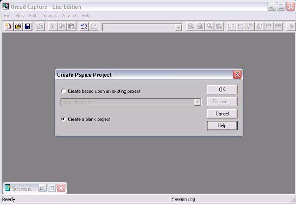
6 Figure 2 Procedures: Getting Started: To use the Orcad Pspice, the following steps must be followed: 1. Create a folder called your name for this Experiment in your Z drive. 2. Click start ->Programs ->Orcad->Capture CIS Lite Edition. 3. Click->File->New->Project. 4. Give the project a name and select Analog or Mixed A/D. You will also be prompted to enter the location you would like to create the file. Put it in your folder created above. Then click OK. This is shown in the following figure. 5. You will then be shown a screen which has two options. Choose the option which says Create a blank project. Then click OK. 6

7 7

8 6. Now you should be on a screen, as shown, which has grid dots located on it. If you do not see a tools box on the right hand side of the page then left click on the mouse and one should appear at this time. Experiment 1: DC Circuit of Independent Sources 1. Building the circuit: First of all, you have to build the following circuit shown in Figure 3. It is required to find the current in R1 and R2 and the voltage on the current source. Figure 3 8
 NOTE: There is a library box containing the libraries which hold the required parts.")

9 1) First, to get the 2 resistors, you can either select the second box in the toolbar on the right or by clicking Place from the top of the screen followed by Part. Both these methods will lead to a screen, shown in Figure 4, where you will be prompted for the part name. 2) NOTE: There is a library box containing the libraries which hold the required parts. At this time, ensure that the two main libraries that you will be using are in this box. The two libraries are: a) Analog. b) Source. If these are not shown here, you must click Add library and these two libraries along with some others will appear. Click on the two libraries mentioned above from the shown Libraries in Figure 5. Figure 4 Figure 5 3) To get the resistors, ensure that you have highlighted Analog library as shown in Figure 6. Then, you can type R or r in the place part box and you should see a picture of a resistor in the graphic box. Click Ok. 9
 to the next resistor position and left click again.")
10 Or, the resistance could also be obtained by scrolling to R in the "part list" and clicking "Ok". Figure 6 4) To place the resistor, drag it to the desired position and then left click the mouse. As shown in Figure 7, if more than one resistor is required, simply move the mouse (with the resistor symbol still attached) to the next resistor position and left click again. Once all required resistors are placed in this fashion, right click on the highlighted resistor and then End mode which is clear in Figure 7 in the highlighted menu. At this time it is important to note that Capacitors and Inductors also fall in the Analog library and are represented by C and L, respectively. 5) To rotate a part, click on the part to get it highlighted and then right click and hit rotate. A faster way though is by highlighting and typing CTRL R. 10
 Both the voltage source and current source ( V DC and I DC, respectively) are located in the Source library.")
11 In this example, do this with resistor R2. Note the whole part, not just a label, must be highlighted. Figure 7 6) Both the voltage source and current source ( V DC and I DC, respectively) are located in the Source library. To place them, follow the same process as for the resistor (or capacitor or inductor). However, be sure that the Source library is highlighted in the place part box. Also, once the placement of each source is made, don't forget to "End Mode". 7) The next step is to wire the circuit. To get the wire, there are two places you can go. Either the third box on the Toolbar menu on the right or again in the Place -> Part ->Wire from the top of the screen. The first option is more convenient. 11
12 8) Once the wire box is activated by "left clicking the mouse" it is connected to a part on the schematic by left clicking on either end of the part and then moving the wire to wherever you would like it joined to. Note here that the wire may be changed from "side to side" to "up and down" by left clicking while moving the wire. As with all parts, to stop the wire function right click on the mouse and choose End Wire. 9) Once the wiring is complete, a ground must be added. The ground is found in the toolbar on the right where it says GND. When you click on it, a window named place ground will be opened. Press Add library tab, open PSpice folder, choose library named source. It will appear in the place ground window, choose the symbol named 0 and press OK. This will be the ground of your circuit. Place the ground in the desired position. The best place for this circuit is where it is shown on Figure 3. 10) Next, the value of each element in the circuit must be edited. Left click on the default value of any element and then right click->edit properties to get to the "Edit Properties" screen. Type the required value in the "Value" box. (Note that a "Display Properties" screen can also be reached by double left-clicking on the default value.) There are various options here for what may be displayed with the particular element. For now, use the default. The name of an element may be changed by double clicking on the name (e.g. R1) and editing as was done for the numerical "Value". Congratulations, you have just built your first circuit!! Now, save the schematic to your course directory. 12
13 2. Simulating the Circuit (Bias Point Simulation): 1) If all the previous steps have been properly followed, the circuit is now ready for simulation. Note: Before starting the simulation process, the values of voltage, current and power associated with each resistor should be hand-calculated so that they are used to check the PSpice results (for this initial circuit only). 2) Choose PSpice from the top toolbar and click New simulation Profile. Supply any convenient name when the prompt to do so appears. Then click Create. Now a screen appears which asks for the type of analysis. For this circuit, choose the Bias Point analysis by clicking the drop box and selecting Bias Point. Then click Ok. 3) The simulation is now ready to run. To do so, click PSpice->Run on the top tool bar. A few seconds will elapse while the netlist and output files are being generated. A simulation box, indicating that the simulation is complete should then appear. If there are errors associated with your circuit, the simulator will inform you if there are errors in the circuit at this phase and your circuit will not simulate properly. If no errors are reported, then close this screen to return to the schematic. 4) The voltages and currents in the circuit may be displayed on the schematic by clicking on the big V and big I in the top tool bar. There is also a W which will also show the power in watts. The currents and voltages may be verified against the hand calculations. Figure 9 shows the circuit after simulation with the voltages, currents, and power displayed. If 13
14 you press on the V, I and W buttons one more time, the values read will disappear. Figure 9 Note: There are quick buttons, in the upper toolbar, shown in the following figure, to be used for opening a new simulation profile (the left button) or editing the simulation profile (the middle one) or running the simulation (the right one). 3. DC Sweep: 1) For the same circuit, we will do a DC sweep which is used to calculate various currents or voltages over a certain range of values swept of a certain controlling device. 2) To change the type of simulation from DC bias point to DC sweep, open the PSpice tab in the upper tool bar and open Edit Simulation Profile. 3) Set the type of simulation to DC sweep. 4) Set primary sweep to voltage source. 5) Set voltage name to V1 which is the name of the voltage source in the circuit and set the start and end values and the increment 0, 10 and 1V as 14
 Run the simulation.")
15 shown in Figure 10 then press Ok. (i.e. This means that the component that we will sweep its values is V1 and the values range is from 0V to 10V with 1V as an increment). Figure 10 Simulation Settings 8) Run the simulation. 9) To view the output, put the voltage marker on the node on which you want to measure the voltage, or current marker on the branch in which you want to measure the current; the markers are placed at the upper toolbar. Or instead of the markers, after running the simulation, a black screen will be opened like the one shown below on the left, this is the output screen, you can add trace by opening the Trace tab in the upper toolbar of the window, and press add trace, the right side window shown will be opened, then you can choose which item to view as shown in the list in 15


16 Figure 11. We will choose the voltage on R 2, it will be as shown in Figure 12. Figure 11 Simulation Results. 16
17 Experiment 2: DC Circuit with Dependent Sources PSpice can be used to analyze circuits that contain dependent sources. The PSpice symbols used to represent dependent sources are Symbol Description PSpice Name Library F1 F CCCS (Current Controlled Current Source) F G1 + - G E1 + - E + - VCCS (Voltage Controlled Current Source) VCVS (Voltage Controlled Voltage Source) G E Analog Library H1 H + - CCVS (Current Controlled Voltage Source) H 1. Building the circuit: First of all, you have to build the following circuit shown in Figure 12. It is required to find currents in all branches and voltages on all nodes. Figure 13 shows the connected circuit on PSpice. Figure 12 17
18 R2 2 F1 R4 5 R1 1k F 10Vdc V1 R3 R5 3 6 Figure 13 Note: How to edit the dependent source gain: - Select the dependent source then right click on it. - From the list menu select Edit Part as shown in Fig. 14 Figure 14 18


19 - The dependent source will be opened alone in a new window - Select options from the top tool bar, then select part properties as in Fig Change the gain to be 5 as shown in Fig. 16 and click ok. Figure 15 Figure 16 19

20 - Exit the file where the CCCS has been edited and select update current when you are asked the question about updating the source as shown in Fig.17 - The final step is to simulate the circuit shown in Fig. 18, using Bias point analysis. Exit here Update Current Figure 17 20
21 2.087A R V R mA V 5.243V 728.2mA R4 5 F V 145.6mA 728.2mA mA-728.2mA F 5.243V 10Vdc V A R mA R A 0V 0 Figure 18 21
Introduction to OrCAD. Simulation Program With Integrated Circuits Emphasis.
 Islamic University of Gaza Faculty of Engineering Electrical Engineering department Digital Electronics Lab (EELE 3121) Eng. Mohammed S. Jouda Eng. Amani S. abu reyala Experiment 1 Introduction to OrCAD
A Brief Handout for Introduction to
 A Brief Handout for Introduction to Electric cal Engineering Course This handout is a compilation of PSPICE, A Brief Primer, Department of Electrical and Systems Engineering, University of Pennsylvania
Engineering 3821 Fall Pspice TUTORIAL 1. Prepared by: J. Tobin (Class of 2005) B. Jeyasurya E. Gill
 B. Jeyasurya E. Gill") Engineering 3821 Fall 2003 Pspice TUTORIAL 1 Prepared by: J. Tobin (Class of 2005) B. Jeyasurya E. Gill 2 INTRODUCTION The PSpice program is a member of the SPICE (Simulation Program with Integrated Circuit
Engineering 3821 Fall 2003 Pspice TUTORIAL 1 Prepared by: J. Tobin (Class of 2005) B. Jeyasurya E. Gill 2 INTRODUCTION The PSpice program is a member of the SPICE (Simulation Program with Integrated Circuit
ECE 201 LAB 6 INTRODUCTION TO SPICE/PSPICE
 Version 1.1 1 of 33 BEFORE YOU BEGIN PREREQUISITE LABS Resistive Circuits EXPECTED KNOWLEDGE ECE 201 LAB 6 INTRODUCTION TO SPICE/PSPICE Ohm's Law: v = ir Node Voltage and Mesh Current Methods of Circuit
PSPICE T UTORIAL P ART I: INTRODUCTION AND DC ANALYSIS. for the Orcad PSpice Release 9.2 Lite Edition
 PSPICE T UTORIAL P ART I: INTRODUCTION AND DC ANALYSIS for the Orcad PSpice Release 9.2 Lite Edition INTRODUCTION The Simulation Program with Integrated Circuit Emphasis (SPICE) circuit simulation tool
Electric Circuit Fall 2015 Pingqiang Zhou. ShanghaiTech University. School of Information Science and Technology. Professor Pingqiang Zhou
 ShanghaiTech University School of Information Science and Technology Professor Pingqiang Zhou LABORATORY 2 CAD Tools Guide Practical circuit design occurs in three stages: 1. Design of an appropriate circuit
OrCAD PSpice - Tutorial. TA: 黃玉龍
 OrCAD PSpice - Tutorial TA: 黃玉龍 r9994320@ntu.edu.tw Outline 2 Introduction Preparation Schematic Simulation Conclusion Introduction 3 OrCAD PSpice is developed by Cadence Analog circuit simulation tool
EXPERIMENT NUMBER 10 TRANSIENT ANALYSIS USING PSPICE
 EXPERIMENT NUMBER 10 TRANSIENT ANALYSIS USING PSPICE Objective: To learn to use a circuit simulator package for plotting the response of a circuit in the time domain. Preliminary: Revise laboratory 8 to
Week 1: Preparing for PSpice Simulations
 Week 1: Preparing for PSpice Simulations Week 1 is composed of two experiments from the lab manual Experiment 1: Breadboard Basics Experiment 3: Ohm s Law Separate lectures on Modules will be posted for
Introduction to SPICE. Simulator of Electronic devices
 Introduction to SPICE Simulator of Electronic devices Main steps: Download Instalation Open OrCAD capture CIS Lite Create a circuit. Place parts. Design a Simulation Profile Run PSpice F11 View simulation
Introduction to LT Spice IV with Examples
 Introduction to LT Spice IV with Examples 400D - Fall 2015 Purpose Part of Electronics & Control Division Technical Training Series by Nicholas Lombardo The purpose of this document is to give a basic
EE 210 Lab Exercise #3 Introduction to PSPICE
 EE 210 Lab Exercise #3 Introduction to PSPICE Appending 4 in your Textbook contains a short tutorial on PSPICE. Additional information, tutorials and a demo version of PSPICE can be found at the manufacturer
Background Theory and Simulation Practice
 CAD and Simulation Objectives Experiment Topic: CAD and Simulation PSpice 9.1 Student Version To obtain your free copy of the software and user s guide, go to Electronics Lab website ( http://www.electronics-lab.com/downloads/schematic/013/
Introduction to Pspice
 1. Objectives Introduction to Pspice The learning objectives for this laboratory are to give the students a brief introduction to using Pspice as a tool to analyze circuits and also to demonstrate the
PSPICE A brief primer
 PSPICE A brief primer Contents 1. Introduction 2. Use of PSpice with OrCAD Capture 2.1 Step 1: Creating the circuit in Capture 2.2 Step 2: Specifying the type of analysis and simulation BIAS or DC analysis
14:332:223 Principles of Electrical Engineering I Instructions for using PSPICE Tools Sharanya Chandrasekar February 1, 2006
 14:332:223 Principles of Electrical Engineering I Instructions for using PSPICE Tools Sharanya Chandrasekar February 1, 2006 1. Getting Started PSPICE is available on the ECE Computer labs in EE 103, DSV
Lab 3: Circuit Simulation with PSPICE
 Page 1 of 11 Laboratory Goals Introduce text-based PSPICE as a design tool Create transistor circuits using PSPICE Simulate output response for the designed circuits Introduce the Curve Tracer functionality.
EECS 312: Digital Integrated Circuits Lab Project 1 Introduction to Schematic Capture and Analog Circuit Simulation
 EECS 312: Digital Integrated Circuits Lab Project 1 Introduction to Schematic Capture and Analog Circuit Simulation Teacher: Robert Dick GSI: Shengshuo Lu Assigned: 5 September 2013 Due: 17 September 2013
EECE Circuits and Signals: Biomedical Applications. Lab 3. Basic Instruments, Components and Circuits. Introduction to Spice and AC circuits
 EECE 2150 - Circuits and Signals: Biomedical Applications Lab 3 Basic Instruments, Components and Circuits. Introduction to Spice and AC circuits Introduction and Preamble: In this lab you will experiment
FACULTY OF ENGINEERING LAB SHEET
 FACULTY OF ENGINEERING LAB SHEET CIRCUITS AND SIGNALS EEL 2186 TRIMESTER 1 (218/219) -Circuit analysis using ORCAD PSpice *Note: You will be given an assessment sheet during the lab session to be completed
An Introductory Guide to Circuit Simulation using NI Multisim 12
 School of Engineering and Technology An Introductory Guide to Circuit Simulation using NI Multisim 12 This booklet belongs to: This document provides a brief overview and introductory tutorial for circuit
Laboratory #2 PSpice Analyses
 Laboratory #2 PSpice Analyses I. Objectives 1. Know the development of SPICE. 2. Learn to install the PSpice software. 3. Learn to use the Capture CIS to draw circuit. 4. Learn to use the four analyses
Electronics I LAB. Lab 1: Lab 1 : Introduction to PsPise
 Electronics I LAB Lab 1: Lab 1 : Introduction to PsPise 1-Introduction to PsPise : SPICE (Simulation Program for Integrated Circuits Emphasis.) is a po werful general purpo se analog and mixed-mode circuit
Introduction to SwitcherCAD
 Introduction to SwitcherCAD 1 PREFACE 1.1 What is SwitcherCAD? SwitcherCAD III is a new Spice based program that was developed for modelling board level switching regulator systems. The program consists
Getting Started with Qucs
 Getting Started with Qucs Graham Edge University of Toronto After downloading Qucs, installing it, and running for the first time you should see a window that looks something like this: The large yellow
Tsung-Chu Huang. Department of Electronic Engineering National Changhua University of Education /10/4-5 TCH NCUE
 Digital IC Design Tsung-Chu Huang Department of Electronic Engineering National Changhua University of Education Email: tch@cc.ncue.edu.tw 2004/10/4-5 Page 1 Circuit Simulation Tools 1. Switch Level: Verilog,
MultiSim and Analog Discovery 2 Manual
 MultiSim and Analog Discovery 2 Manual 1 MultiSim 1.1 Running Windows Programs Using Mac Obtain free Microsoft Windows from: http://software.tamu.edu Set up a Windows partition on your Mac: https://support.apple.com/en-us/ht204009
Figure 1. Main window (Common Interface Window), CIW opens and from the pull down menus you can start your design. Figure 2.
, CIW opens and from the pull down menus you can start your design. Figure 2.") Running Cadence Once the Cadence environment has been setup you can start working with Cadence. You can run cadence from your directory by typing Figure 1. Main window (Common Interface Window), CIW opens
Running Cadence Once the Cadence environment has been setup you can start working with Cadence. You can run cadence from your directory by typing Figure 1. Main window (Common Interface Window), CIW opens
Lab #2 First Order RC Circuits Week of 27 January 2015
 ECE214: Electrical Circuits Laboratory Lab #2 First Order RC Circuits Week of 27 January 2015 1 Introduction In this lab you will investigate the magnitude and phase shift that occurs in an RC circuit
LT Spice Getting Started Very Quickly. First Get the Latest Software!
 LT Spice Getting Started Very Quickly First Get the Latest Software! 1. After installing LT Spice, run it and check to make sure you have the latest version with respect to the latest version available
ENEE207 Electric Circuits Lab Manual
 ENEE207 Electric Circuits Lab Manual Department of Engineering, Physical & Computer Sciences Montgomery College Version 3 Copyright Lan Xiang (Do not distribute without permission) 1 TABLE OF CONTENTS
The default account setup for the class should allow you to run HSPICE without any further configuration. To verify this, type:
 UNIVERSITY OF CALIFORNIA College of Engineering Department of Electrical Engineering and Computer Sciences HW #1: Circuit Simulation NTU IC541CA (Spring 2004) 1 Objective The objective of this homework
Chapter 12: Electronic Circuit Simulation and Layout Software
 Chapter 12: Electronic Circuit Simulation and Layout Software In this chapter, we introduce the use of analog circuit simulation software and circuit layout software. I. Introduction So far we have designed
Electronic Circuit Simulation Tools Using Pspice On Ac Analysis
 Electronic Circuit Simulation Tools Using Pspice On Ac Analysis This Design Idea shows it can handle digital filter simulation too. PSpice has become an industry standard tool for analog circuit simulations.
Introduction to NI Multisim & Ultiboard Software version 14.1
 School of Engineering and Applied Science Electrical and Computer Engineering Department Introduction to NI Multisim & Ultiboard Software version 14.1 Dr. Amir Aslani August 2018 Parts Probes Tools Outline
Fig. 1-1 show the main window of Orcad Capture. Every project you work on will start from Orcad Capture. Fig. 1-1 Orcad Capture Main window.
 T. K. Ha PSpice Lecture #1 1 Objective: By the end of this lecture, it is hope that the students will have a rudimentary knowledge of using and running PSpice. The student will be able to draw and edit
DC Operating Point, I-V Curve Trace. Author: Nate Turner
 DC Operating Point, I-V Curve Trace Author: Nate Turner Description: This tutorial demonstrates how to print the DC-Operating Point as well as trace the I-V curves for a transistor in the tsmc 180nm process.
Since transmission lines can be modeled using PSpice, you can do your analysis by downloading the student version of this excellent program.
 PSpice Analysis Since transmission lines can be modeled using PSpice, you can do your analysis by downloading the student version of this excellent program. PSpice can be downloaded from the following
THE SPICE BOOK. Andrei Vladimirescu. John Wiley & Sons, Inc. New York Chichester Brisbane Toronto Singapore
 THE SPICE BOOK Andrei Vladimirescu John Wiley & Sons, Inc. New York Chichester Brisbane Toronto Singapore CONTENTS Introduction SPICE THE THIRD DECADE 1 1.1 THE EARLY DAYS OF SPICE 1 1.2 SPICE IN THE 1970s
LTSpice Basic Tutorial
 Index: I. Opening LTSpice II. Drawing the circuit A. Making Sure You Have a GND B. Getting the Parts C. Placing the Parts D. Connecting the Circuit E. Changing the Name of the Part F. Changing the Value
The analysis of the linear voltage regulators
 The analysis of the linear voltage regulators 1. Theoretical aspects The voltage regulator is an electronic circuit which, ideally, it provides a constant output voltage. The value of the output voltage
EXPERIMENT 9 Problem Solving: First-order Transient Circuits
 EXPERIMENT 9 Problem Solving: First-order Transient Circuits I. Introduction In transient analyses, we determine voltages and currents as functions of time. Typically, the time dependence is demonstrated
ENGI0531 Lab 2 Tutorial
 ENGI0531 Lab 2 Tutorial Transient Analysis, Operating Points, Parameters and other miscellany Lakehead University Greg Toombs Winter 2009 1. Constructing the Circuit Copying a Cell View Start Cadence as
Using LTSPICE to Analyze Circuits
 Using LTSPICE to Analyze Circuits Overview: LTSPICE is circuit simulation software that automatically constructs circuit equations using circuit element models (built in or downloadable). In its modern
Using LTspice a Short Intro with Examples
 Using LTspice a Short Intro with Examples LTspice, also called SwitcherCAD, is a powerful and easy to use schematic capture program and SPICE engine, which is a general-purpose circuit simulation program
ET 304A Laboratory Tutorial-Circuitmaker For Transient and Frequency Analysis
 ET 304A Laboratory Tutorial-Circuitmaker For Transient and Frequency Analysis All circuit simulation packages that use the Pspice engine allow users to do complex analysis that were once impossible to
Simulating Circuits James Lamberti 5/4/2014
 Simulating Circuits James Lamberti (jal416@lehigh.edu) 5/4/2014 There are many simulation and design platforms for circuits. The two big ones are Altium and Cadence. This tutorial will focus on Altium,
OrCAD 17.2 Pspice Tutorial. High-Speed Circuits & Systems Lab. Yonsei University
 OrCAD 17.2 Pspice Tutorial High-Speed Circuits & Systems Lab. Yonsei University Installation Move to http://www.orcad.com/resources/orcaddownloads#demo Installation Click Download FREE-OrCAD 17.2 Lite
ELEC3106 Electronics. Lab 4: EMI simulations with SPICE. Objective. Material. Simulations
 ELEC3106 Electronics Lab 4: EMI simulations with SPICE Objective The objective of this laboratory session is to give the students a good understanding of the possibilities a circuit simulator (as SPICE)
DEPARTMENT OF ELECTRICAL ENGINEERING. Date: Assistant A2: PSpice 2 PC Pool
 University of Applied Sciences Hamburg Group No : DEPARTMENT OF ELECTRICAL ENGINEERING Laboratory for Instrumentation and Measurement L1: in charge of the report PSpice 2 PC Pool Date: Assistant A2: Professor:
LAB EXERCISE 3 FET Amplifier Design and Linear Analysis
 ADS 2012 Workspaces and Simulation Tools (v.1 Oct 2012) LAB EXERCISE 3 FET Amplifier Design and Linear Analysis Topics: More schematic capture, DC and AC simulation, more on libraries and cells, using
Pulsed Power Engineering Circuit Simulation
 Pulsed Power Engineering Circuit Simulation January 12-16, 2009 Craig Burkhart, PhD Power Conversion Department SLAC National Accelerator Laboratory Circuit Simulation for Pulsed Power Applications Uses
A Short SPICE Tutorial
 A Short SPICE Tutorial Kenneth H. Carpenter Department of Electrical and Computer Engineering Kanas State University September 15, 2003 - November 10, 2004 1 Introduction SPICE is an acronym for Simulation
Circuit Simulation with SPICE OPUS
 Circuit Simulation with SPICE OPUS Theory and Practice Tadej Tuma Arpäd Bürmen Birkhäuser Boston Basel Berlin Contents Abbreviations About SPICE OPUS and This Book xiii xv 1 Introduction to Circuit Simulation
Revised: Summer 2010
 EE 2274 PRE-LAB EXPERIMENT 5 DIODE OR GATE & CLIPPING CIRCUIT COMPLETE PRIOR TO COMING TO LAB Part I: 1. Design a diode, Figure 1 OR gate in which the maximum input current,, Iin is less than 5mA. Show
Experiment 2: Simulation of DC Resistive Circuits
 Experiment 2: Simulation of DC Resistive Circuits Objectives: Simulate DC Resistive circuits using Orcad PSpice Software. Verify experimental and theoretically calculated results for a given resistive
FACULTY OF ENGINEERING LAB SHEET
 FACULTY OF ENGINEERING LAB SHEET CIRCUITS AND SIGNALS EEL 286 TRIMESTER (26/27) -Circuit analysis using ORCAD PSpice Experiment : Circuit analysis using ORCAD Pspice PRECAUTIONARY STEPS:. Read this experiment
Experiment 1 Introduction to Simulink
 1 Experiment 1 Introduction to Simulink 1.1 Objective The objective of Experiment #1 is to familiarize the students with simulation of power electronic circuits in Matlab/Simulink environment. Please follow
ECE4902 Lab 5 Simulation. Simulation. Export data for use in other software tools (e.g. MATLAB or excel) to compare measured data with simulation
 to compare measured data with simulation") ECE4902 Lab 5 Simulation Simulation Export data for use in other software tools (e.g. MATLAB or excel) to compare measured data with simulation Be sure to have your lab data available from Lab 5, Common
ECE4902 Lab 5 Simulation Simulation Export data for use in other software tools (e.g. MATLAB or excel) to compare measured data with simulation Be sure to have your lab data available from Lab 5, Common
HSPICE (from Avant!) offers a more robust, commercial version of SPICE. PSPICE is a popular version of SPICE, available from Orcad (now Cadence).
 offers a more robust, commercial version of SPICE. PSPICE is a popular version of SPICE, available from Orcad (now Cadence).") Electronics II: SPICE Lab ECE 09.403/503 Team Size: 2-3 Electronics II Lab Date: 3/9/2017 Lab Created by: Chris Frederickson, Adam Fifth, and Russell Trafford Introduction SPICE (Simulation Program for
Electronics II: SPICE Lab ECE 09.403/503 Team Size: 2-3 Electronics II Lab Date: 3/9/2017 Lab Created by: Chris Frederickson, Adam Fifth, and Russell Trafford Introduction SPICE (Simulation Program for
Ansoft Designer Tutorial ECE 584 October, 2004
 Ansoft Designer Tutorial ECE 584 October, 2004 This tutorial will serve as an introduction to the Ansoft Designer Microwave CAD package by stepping through a simple design problem. Please note that there
SPICE FOR POWER ELECTRONICS AND ELECTRIC POWER
 SPICE FOR POWER ELECTRONICS AND ELECTRIC POWER SECOND EDITION MUHAMMAD H. RASHID University of West Florida Pensacola, Florida, U.S.A. HASAN M. RASHID University of Florida Gainesville, Florida, U.S.A.
Lab 3: Very Brief Introduction to Micro-Cap SPICE
 Lab 3: Very Brief Introduction to Micro-Cap SPICE Starting Micro-Cap SPICE Micro-Cap SPICE is available on CoE machines under the Spectrum Software menu: Programs Spectrum Software Micro-Cap 10 Evaluation
Circuit Shop v December 2003 Copyright Cherrywood Systems. All rights reserved.
 Circuit Shop v2.02 - December 2003 Copyright 1997-2003 Cherrywood Systems. All rights reserved. This manual is a printable version of Circuit Shop's help file. There are two parts to the manual: The first
EE 221 L CIRCUIT II. Learn to use LTspice to run circuit simulations for voltage, current, etc.
 EE 221 L CIRCUIT II LABORATORY 3: LTSPICE DEPARTMENT OF ELECTRICAL AND COMPUTER ENGINEERING UNIVERSITY OF NEVADA, LAS VEGAS OBJECTIVE Learn to use LTspice to run circuit simulations for voltage, current,
Welcome to SPDL/ PRL s Solid Edge Tutorial.
 Smart Product Design Product Realization Lab Solid Edge Assembly Tutorial Welcome to SPDL/ PRL s Solid Edge Tutorial. This tutorial is designed to familiarize you with the interface of Solid Edge Assembly
UNIVERSITY OF CALIFORNIA College of Engineering Department of Electrical Engineering and Computer Sciences
 UNIVERSITY OF CALIFORNIA College of Engineering Department of Electrical Engineering and Computer Sciences Jan M. Rabaey Homework #1: Circuit Simulation EECS 141 Due Friday, January 29, 5pm, box in 240
Mor M. Peretz Power Electronics Laboratory Department of Electrical and Computer Engineering Ben-Gurion University of the Negev, ISRAEL
 Mor M. Peretz Power Electronics Laboratory Department of Electrical and Computer Engineering Ben-Gurion University of the Negev, ISRAEL [1] PSpice A/D simulation program allows to analyze electrical circuits
OrCAD PSpice A/D, OrCAD PSpice AA and AMS Simulator
 Title: Product: Summary: Using AutoConvergence OrCAD PSpice A/D, OrCAD PSpice AA and AMS Simulator The convergence problem will be described briefly in this application note and the AutoConvergence feature
SIMULATION WITH THE CUK TOPOLOGY ECE562: Power Electronics I COLORADO STATE UNIVERSITY. Modified in Fall 2011
 SIMULATION WITH THE CUK TOPOLOGY ECE562: Power Electronics I COLORADO STATE UNIVERSITY Modified in Fall 2011 ECE 562 Cuk Converter (NL5 Simulation) Laboratory Page 1 PURPOSE: The purpose of this lab is
Schematic and Layout Simulation Exercise
 University of California, Berkeley EE141 Fall 2009 Laboratory Exercise 4 Schematic and Layout Simulation Exercise The objective of this laboratory exercise is to walk you through the process of simulating
Experiment # 1 Introduction to Lab Equipment
 Experiment # 1 Introduction to Lab Equipment 1. Synopsis: In this introductory lab, we will review the basic concepts of digital logic design and learn how to use the equipment available in the laboratory.
John von Neumann Faculty of Informatics F1. Basics of MicroCap. After the launching of the MicroCap 9 the following screen appears:
 Basics of MicroCap 1. MicroCap Based on the Electronics lectures the student learn the acquired knowledge in practice. For this the MicroCap simulation software will be used in the practical courses. The
ECE 220 Laboratory 3 Thevenin Equivalent Circuits, Constant Current Source, and Inverting Amplifier
 ECE 220 Laboratory 3 Thevenin Equivalent Circuits, Constant Current Source, and Inverting Amplifier Michael W. Marcellin The first portion of this document describes preparatory work to be completed in
Laboratory Experiment #1 Introduction to Spectral Analysis
 J.B.Francis College of Engineering Mechanical Engineering Department 22-403 Laboratory Experiment #1 Introduction to Spectral Analysis Introduction The quantification of electrical energy can be accomplished
EEC 116 Fall 2011 Lab #2: Analog Simulation Tutorial
 EEC 116 Fall 2011 Lab #2: Analog Simulation Tutorial Dept. of Electrical and Computer Engineering University of California, Davis Issued: September 28, 2011 Due: October 12, 2011, 4PM Reading: Rabaey Chapters
Lab 7 PSpice: Time Domain Analysis
 Lab 7 PSpice: Time Domain Analysis OBJECTIVES 1. Use PSpice Circuit Simulator to simulate circuits containing capacitors and inductors in the time domain. 2. Practice using a switch, and a Pulse & Sinusoidal
EECE 488: Short HSPICE Tutorial. Last updated by: Mohammad Beikahmadi January 2013
 EECE 488: Short HSPICE Tutorial Last updated by: Mohammad Beikahmadi January 2013 SPICE? Simulation Program with Integrated Circuit Emphasis An open source analog circuit simulator Predicts circuit behavior,
EECS 312: Digital Integrated Circuits Lab Project 2 Extracting Electrical and Physical Parameters from MOSFETs. Teacher: Robert Dick GSI: Shengshuo Lu
 EECS 312: Digital Integrated Circuits Lab Project 2 Extracting Electrical and Physical Parameters from MOSFETs Teacher: Robert Dick GSI: Shengshuo Lu Due 3 October 1 Introduction In this lab project, we
Creo Revolve Tutorial
 Creo Revolve Tutorial Setup 1. Open Creo Parametric Note: Refer back to the Creo Extrude Tutorial for references and screen shots of the Creo layout 2. Set Working Directory a. From the Model Tree navigate
Introduction to LTSpice
 Usage of Introduction to Department of EECS Jacobs University Bremen Instructors - Dr. Mathias Bode and - e-mail - m.bode@jacobs-university.de tel.: +49 421 200-3139 - u.pagel@jacobs-university.de tel.:
Experiment Number 2. Revised: Fall 2018 PLECS RC, RL, and RLC Simulations
 Experiment Number 2 Revised: Fall 2018 PLECS RC, RL, and RLC Simulations Preface: Experiment number 2 will be held in CLC room 105, 106, or 107. Your TA will let you know Preliminary exercises are to be
SPICE for Power Electronics and Electric Power
 SPICE for Power Electronics and Electric Power Third Edition Muhammad H. Rashid Life Fellow IEEE /^0\ \Cf*' CRC Press I Taylor & Francis eis Crou Group Boca Raton London New York CRC Press is an imprint
EECE 488: Short HSPICE. Tutorial. Last updated by: Mohammad Beikahmadi January Original presentation by: Jack Shiah
 EECE 488: Short HSPICE Tutorial Last updated by: Mohammad Beikahmadi January 2012 Original presentation by: Jack Shiah SPICE? Simulation Program with Integrated Circuit Emphasis An open source analog circuit
PSIM SmartCtrl link. SmartCtrl Tutorial. PSIM SmartCtrl link Powersim Inc.
 SmartCtrl Tutorial PSIM SmartCtrl link - 1 - Powersim Inc. SmartCtrl1 1 is a general-purpose controller design software specifically for power electronics applications. This tutorial is intended to guide
Simulation Guide. The notes in this document are intended to give guidance to those using the demonstration files provided for
 Simulation Guide The notes in this document are intended to give guidance to those using the demonstration files provided for Electronics: A Systems Approach 2nd Edition by Neil Storey. Demonstration files
ENGR-4300 Fall 2006 Project 3 Project 3 Build a 555-Timer
 ENGR-43 Fall 26 Project 3 Project 3 Build a 555-Timer For this project, each team, (do this as team of 4,) will simulate and build an astable multivibrator. However, instead of using the 555 timer chip,
Class #8: Experiment Diodes Part I
 Class #8: Experiment Diodes Part I Purpose: The objective of this experiment is to become familiar with the properties and uses of diodes. We used a 1N914 diode in two previous experiments, but now we
EE 2274 RC and Op Amp Circuit Completed Prior to Coming to Lab. Prelab Part I: RC Circuit
 EE 2274 RC and Op Amp Circuit Completed Prior to Coming to Lab Prelab Part I: RC Circuit 1. Design a high pass filter (Fig. 1) which has a break point f b = 1 khz at 3dB below the midband level (the -3dB
Curve Tracer Laboratory Assistant Using the Analog Discovery Module as A Curve Tracer
 Curve Tracer Laboratory Assistant Using the Analog Discovery Module as A Curve Tracer The objective of this lab is to become familiar with methods to measure the dc current-voltage (IV) behavior of diodes
EE 2274 DIODE OR GATE & CLIPPING CIRCUIT
 EE 2274 DIODE OR GATE & CLIPPING CIRCUIT Prelab Part I: Wired Diode OR Gate LTspice use 1N4002 1. Design a diode OR gate, Figure 1 in which the maximum current thru R1 I R1 = 9mA assume Vin = 5Vdc. Design
Experiment Number 1. Revised: Fall 2018 Introduction to MATLAB Simulink and Simulink Resistor Simulations Preface:
 Experiment Number 1 Revised: Fall 2018 Introduction to MATLAB Simulink and Simulink Resistor Simulations Preface: Experiment number 1 will be held in CLC room 105, 106, or 107. Your TA will let you know
Multisim 10 Component Reference Guide Pdf
 Multisim 10 Component Reference Guide Pdf Getting Started with Multisim Component Evaluator To comment on National Instruments documentation, refer to the National 10 Spreadsheet View. Equipment and Components
Alibre Design Tutorial - Simple Extrude Step-Pyramid-1
 Alibre Design Tutorial - Simple Extrude Step-Pyramid-1 Part Tutorial Exercise 4: Step-Pyramid-1 [text version] In this Exercise, We will set System Parameters first. Then, in sketch mode, outline the Step
EE140: Lab 5, Project Week 2
 Introduction EE140: Lab 5, Project Week 2 VGA Op-amp Group Presentations: 4/13 and 4/14 in Lab Slide Submission: 4/15/17 (9 am) For this lab, you will be developing the background and circuits that you
Faculty of Engineering 4 th Year, Fall 2010
 4. Inverter Schematic a) After you open the previously created Inverter schematic, an empty window appears where you should place your components. To place an NMOS, select Add- >Instance or use shortcut
PSPICE SIMULATIONS WITH THE RESONANT INVERTER POWER ELECTRONICS COLORADO STATE UNIVERSITY. Created by Colorado State University student
 PSPICE SIMULATIONS WITH THE RESONANT INVERTER POWER ELECTRONICS COLORADO STATE UNIVERSITY Created by Colorado State University student Page 1 of 13 PURPOSE: The purpose of this lab is to simulate the resonant
Experiment Number 2. Revised: Summer 2013 PLECS RC, RL, and RLC Simulations
 Preface: Experiment Number 2 Revised: Summer 2013 PLECS RC, RL, and RLC Simulations Preliminary exercises are to be done and submitted individually Laboratory simulation exercises are to be done individually
Lab 15: Lock in amplifier (Version 1.4)
") Lab 15: Lock in amplifier (Version 1.4) WARNING: Use electrical test equipment with care! Always double-check connections before applying power. Look for short circuits, which can quickly destroy expensive
Lab 15: Lock in amplifier (Version 1.4) WARNING: Use electrical test equipment with care! Always double-check connections before applying power. Look for short circuits, which can quickly destroy expensive
LABORATORY 4. Palomar College ENGR210 Spring 2017 ASSIGNED: 3/21/17
 LABORATORY 4 ASSIGNED: 3/21/17 OBJECTIVE: The purpose of this lab is to evaluate the transient and steady-state circuit response of first order and second order circuits. MINIMUM EQUIPMENT LIST: You will