A HIGH FIDELITY GLOBAL POSITIONING SYSTEM RECEIVER SIMULATION. A Thesis Presented to. The Faculty of the. Fritz J. and Dolores H.
|
|
|
- Giles Hunt
- 5 years ago
- Views:
Transcription
1 A HIGH FIDELITY GLOBAL POSITIONING SYSTEM RECEIVER SIMULATION A Thesis Presented to The Faculty of the Fritz J. and Dolores H. Russ College of Engineering and Technology Ohio University In Partial Fulfillment of the Requirements for the Degree Master of Science Andrew C. Seitz March, 2000
2 + l'i, THIS THESIS ENTITLED "A HIGH FIDELITY GLOBAL POSITIONING SYSTEM RECEIVER SIMULATION" by Andrew C. Seitz has been approved for the School of Electrical Engineering and Computer Science and the Russ College of Engineering and Technology * i '1,? t *.i i k,dw2c, -,YJ! 6 ~~/42,fi,, Michael S. Braasch, Ph.D., P.E. Associate Professor of Electrical Engineering - Warren K. Wray, Dean Fritz J. and Dolores H. Rus College of Engineering and Technology
3 Acknowledgments The research described in this thesis was funded by the Joint University Program for Air Transportation Research which is sponsored by the National Aeronautics and Space Administration and the Federal Aviation Administration. The author wishes to express his appreciation for the commitment and support that was provided by Dr. Michael Braasch, Assistant Professor of Electrical Engineering. Not only has Dr. Braasch been very supportive in my undertaking of this research, he has extended his guidance beyond the expected dedication to create not only a knowledgeable engineer, but a well rounded professional. A sincere thank you is given to Dr. Frank van Graas, Professor of Electrical Engineering, for sharing his engineering expertise particularly in the area of GPS and for serving as a member of the thesis committee. Dr. Dennis Irwin, Professor and Chair of the School of Electrical Engineering and Computer Science is thanked for his advice on control systems and for his part in the thesis committee. Dr. William Reeves, Professor of Industrial Technology is thanked for his insight throughout the quest for this degree and for serving as a member of the thesis committee. The author would also like to thank his parents, Gary and Margaret Seitz for their love and support (both financial and emotional) throughout many years of education, and to Brian Seitz and Kelli Bates for their help in keeping things in perspective. In addition, thanks are also given to my friends and family members for their encouragement. Thanks is also given to the staff of the Avionics Engineering Center at Ohio University for their uncanny support. At last, thanks is given to the heavenly Father.
4 TABLE OF CONTENTS I. INTRODUCTION GLOBAL POSITIONING SYSTEM BACKGROUND... 4 A. Overview of the Global Positioning System... 4 B. Satellite Navigation Techniques Pseudorange Description Other Measurement Techniques... 7 C. GPS Signal Specifications Signal Structure CIA Code Analysis CIA Code Generation Noise Specifications GLOBAL POSITIONING SYSTEM RECEIVERS A. Receiver Structure B. Phase-Locked Loops C. Effects of Noise on Tracking Loops D. Frequency Synthesis E. Carrier Tracking Loops F. Non-Coherent Code Tracking Loops IV. IMPLEMENTATION OF A HIGH FIDELITY GLOBAL POSITIONING SYSTEM RECEIVER SIMULATION A. Overview of Simulation Software B. Simulation Overview C. Description of System Components GPS Signal Generator Signal Anomalies Correlation Process Numerically Controlled Oscillator Loop Filters Carrier Tracking Loop Code Tracking Loop D. Parameter Selection and Running the Simulation V. CONCLUSIONS AND RECOMMENDATIONS 81 VI. REFERENCES VII. APPENDIX A (Receiver Simulation Output Plots) 86
5 VIII. APPENDIX B (Plots of Code Tracking Loop Error) IX. APPENDIX C (Original SPW Simulation Block Diagrams) v
6 LIST OF FIGURES vi Figure 2.1 Figure 2.2 Figure 2.3 Figure 3.1 Figure 3.2 Figure 3.3 Figure 3.4 Figure 3.5 Figure 3.6 Figure 3.7 Figure 3.8 Figure 3.9 Figure 4.1 Figure 4.2 Figure 4.3 Figure 4.4 Figure 4.5 Figure 4.6 Figure 4.7 Figure 4.8 Generation of GPS L1 signal Normalized autocorrelation function of GPS CIA code Typical GPS CIA code generator GPS signal down-conversion process Separation of a signal into in-phase and qudraphase components Signal correlation process as performed in a GPS receiver Theoretical phase-locked loop Numerically controlled oscillator GPS receiver carrier tracking loop Ideal block diagram of delay-locked loop Typical GPS receiver code tracking loop implementation Standard deviation of code loop tracking error as a function of the carrier-to-noise (CN. ) of the signal for a 0.1 chip spacing Example SPW Block Diagram Editor (BDE) screen Example SPW Signal Calculator (SigCalc) screen Example SPW Simulation Manager screen Overview block diagram of the high fidelity GPS receiver simulation.. 50 GPS signal generator for the high fidelity GPS receiver simulation High fidelity GPS receiver simulation receiver noise implementation.. 54 Generation of the in-phase and quadrature representation of the GPS signal for the high fidelity GPS receiver simulation Correlators for the high fidelity GPS receiver simulation... 59
7 Figure 4.9 Figure 4.10 Figure 4.11 Figure 4.12 Figure 4.13 Figure 4.14 Figure 4.15 Figure 4.16 Figure 4.17 Figure A. 1 Figure A.2 Figure A.3 Figure A.4 Figure A.5 vi i Implementation of a numerically controlled oscillator for the high fidelity GPS receiver simulation First order filter for use in a second order tracking loop High fidelity GPS receiver simulation carrier tracking loop Code tracking loop for the high fidelity GPS receiver simulation Normalized early-minus-late discriminator function for the high fidelity GPS receiver simulation Code tracking loop error for a wide bandwidth first order code tracking loop. The sampling frequency of the simulation was 22 MHz with an early-to-late chip spacing of 0.1 chips. The carrier-to-noise (C/N,) value was 33 db-hz Theoretical standard deviation values for code tracking error versus simulation results Theoretical frequency response for wide NEB first order loop Theoretical frequency response for narrow NEB first order loop Example output from the high fidelity GPS receiver simulation GPS signal generator. The IF frequency for the simulation was 4 times the MHz CIA code. The navigation data is a 50 Hz data stream Example output from the high fidelity GPS receiver simulation. These signals represent the generated GPS signal and the same signal buried in noise (43 db C/No). The sampling rate for the simulation was 22 MHz.87 Probability distribution function (pdf) for receiver noise generated at a 43 db-hz C/No Actual signal-to-noise ratio (SNR) values for the received GPS signal for the high ridelity GPS receiver simulation. The true SNR is approximately -23 db Example output for the high fidelity GPS receiver simulation within the correlation stages of the receiver. The first two signals represent the received signal in its in-phase and quadrature representation. The later two signals show the received GPS signal as it appears after correlation with the prompt copy of the locally generated CIA code. The sampling rate for the simulation was 22 MHz
8 Figure A.6 Figure A.7 Figure B. 1 Figure B.2 Figure B.3 Figure B.4 Figure B.4 Figure B.4 Figure B.4 Figure C. 1 Figure C.2 Figure C.3 Figure C.4 Figure C.5 Example output from the CIA code generators in the High fidelity GPS receiver simulation. The sampling rate for this simulation was 22 MHz with a 0.1 chip spacing between the early and late C/A codes A zoomed in view from the output of the CIA code generators in the high fidelity GPS receiver simulation. The sampling rate for this simulation was 22 MHz with a 0.1 chip early to late spacing between the generated CIA codes Code tracking loop error for a 0.04 Hz NEB first order code tracking loop operating at a 28 db-hz C/N, Code tracking loop error for a 0.04 Hz NEB first order code tracking loop operating at a 32 db-hz C/No Code tracking loop error for a 0.04 Hz NEB first order code tracking loop operating at a 36 db-hz C/No Code tracking loop error for a 0.04 Hz NEB first order code tracking loop operating at a 40 db-hz C/N, Vlll Code tracking loop error for a 0.04 Hz NEB first order code-tracking loop operating at a 43 db-hz C/N, Code tracking loop error for a 0.04 Hz NEB first order code tracking loop operating at a 48 db-hz C/No Code tracking loop error for a 0.04 Hz NEB first order code tracking loop operating at a 50 db-hz C/No Original block diagram of high fidelity GPS receiver simulation Original GPS signal generator block diagram Original receiver noise signal anomaly implementation i00 Original implementation of Costas type phase-locked loop Original implementation of the delay-locked loop
9 ix LIST OF TABLES Table 4.1 High fidelity GPS receiver simulation parameters
10 LIST OF ABBREVIATIONS AGC - Automatic Gain Control BDE - Signal Processing WorkSystem Block Diagram Editor BPSK - Bi-Phase Shift Keying CDMA - Code Division Multiple Access CIA code - Coarse Acquisition pseudorandom noise code DLL - Delay Locked Loop DDS - Direct Digital Synthesis DSSS - Direct Sequence Spread Spectrum DoD - Department of Defense DPLL - Digital Phase Locked Loop DME - Distance Measuring Equipment FLL - Frequency Locked Loop GPS - Global Positioning System GUI - Graphical User Interface LOS - Line of Sight NCO - Numerically Controlled Oscillator NEB - Noise Equivalent Bandwidth OCS - Operation Control Segment PLL - Phase-Locked Loop PN - Pseudorandom PPS - Precise Positioning Service PRN - Pseudorandom Noise P(Y) code - Un-encrypted (P) or encrypted (Y) pseudorandom noise code SigCalc - Signal Processing WorkSystem Signal Calculation Tool SPS - Standard Positioning Service SPW - Signal Processing WorkSystem QPSK - Quadrature Phase Shift Keying XOR - Exclusive OR VCO - Voltage Controlled Oscillator
11 1. INTRODUCTION The Global Positioning System (GPS) is finding its way into many facets of modem technology. GPS is a satellite-based navigation system that provides users with a position fix virtually anywhere on Earth or in orbit around the Earth. Currently the system is popular, not only for use in automobile, aircraft and marine navigation, but in other areas such as farming and telecommunications. Because of the growing use, GPS receiver design is becoming more important as technology changes and users require more accuracy. A microcomputer-based GPS receiver simulation can be used to analyze the operation of GPS receivers. A high fidelity (low level) GPS receiver simulation can provide extensive knowledge of the behavior of all types of GPS receiver technologies that are common today. In addition, a high fidelity simulation could be a powerful tool for building the next generation receiver. The goal for this research was to develop a high fidelity GPS receiver simulation that will allow for the study of the inner-workings of a practical receiver implementation. A common problem in research is the use of sometimes limiting mathematical approximations and assumptions that are only true for a limited number of cases. A high fidelity GPS receiver simulation can provide researchers and design engineers with firsthand knowledge of the effects of signal anomalies without relying on approximations. If a receiver simulation could be developed that provides an emulation of all of the signals inside a GPS receiver without actually building a prototype, problems could be solved without the cost involved in creating unnecessary hardwired circuitry. The receiver simulation that was developed provides high fidelity by emulating the low level functions of a GPS receiver. These low level functions include the
12 operation of the code and carrier tracking loops that are used in a GPS receiver. The 2 simulation was developed using Signal Processing Worksystem (SPW) which is a communications/control system analysis software package. The SPW environment uses a Graphical User Interface (GUI) to aid in the development of systems using block diagrams, and then provides methods for analysis of the designed systems. Inherent in the SPW design environment is a vast array of communications and signal processing blocks including many of the components necessary to form a GPS receiver. There are many ways to develop GPS receivers and the methods used for this high fidelity simulation target only some of the possible receiver architectures. However, there are some basic principles that are similar for most architectures. For example, the code and carrier tracking loops are based in part on theoretical phaselocked loops. The research presented in this thesis will discuss the makeup of a typical GPS receiver and provide a starting point for building a GPS receiver simulation with a more specific purpose in software. After a basic level simulation structure has been established, additions to the model can be implemented to study some of the common GPS problems that are degrading the accuracy of the user. Noise effects, multipath uncertainties, and problems with atmospheric divergence are only a few of the possible uses for a high fidelity simulation. The information provided in this thesis is structured to present the important ideas behind GPS and GPS receiver operation, and to describe a working high fidelity GPS receiver simulation. Chapter two of this thesis provides some background information on GPS and the GPS signal structure. Topics relating to the use and
13 generation of pseudo-random noise (PRN) codes will be discussed as well as issues 3 regarding the classification of noise levels in the GPS system. This information is important when considering a design for a GPS receiver. Chapter three discusses the make-up of a modem day non-coherent GPS receiver. This type of receiver will be the basis for the model that is used for the software emulation. Chapter four describes the SPW implementation of a high fidelity GPS receiver. Also in this chapter is an overview of the SPW software environment and some instructions for running a simulation using the software receiver. The final chapter, Chapter five, presents the concluding remarks for the research. The appendices attached at the end of this document include some data collected from the simulation (Appendix A and B) and the original simulation block diagrams (Appendix C).
14 11. GLOBAL POSITIONING SYSTEM BACKGROUND This section will present some general background information on the Global Positioning System (GPS), and will provide an overview of some of the navigation methods that are currently implemented using the system. In addition, topics dealing with the GPS signal specifications in terms of signal structure and noise issues will be covered. A. Overview of the Global Positioning System The Global Positioning System is a global navigation and positioning system that was conceptualized by the United States Department of Defense (DoD) in the 1960's and first implemented in the 1970's. This satellite positioning system uses 24 satellites in six orbital planes around the earth. However, government studies are exploring the use of additional satellites and the introduction of pseudolites (ground based GPS signal transmitters) to augment the system. The benefits of GPS as a navigation system are very broad. The first benefit is that the measurements are made available world-wide twenty four hours a day. Secondly, the system is passive meaning that it does not require the user to reply back in order to make a successful navigation measurement. Other systems such as the widely used distance measuring equipment (DME) require the user set to be a transponder (requiring the user to transmit as well as receive). Lastly, like other radio navigational aids, the system is available for use in all weather conditions. These factors make the GPS satellite constellation a valuable resource for navigation related needs.
15 The GPS system is divided into three segments. The first is the space segment 5 which contains the satellites arranged in 6 orbital planes at 55O inclination angles with respect to the equatorial plane around the earth. These satellites contain all of the equipment responsible for generating and transmitting the GPS signal including atomic reference standards (atomic clocks) and the equipment for manipulating the signal as needed by the DoD. The control segment, named the operation control system (OCS) is responsible for locating the position of the satellites relative to the earth and for uploading the navigation data that will in turn be re-transmitted. This data contains corrections generated by the OCS to allow users to determine their position with a great deal of accuracy. The final segment is the user segment that includes all receivers on various platforms regardless of the use. For example, all receivers used in aircraft, for farming, surveying, time transfer, or attitude determination are part of the user segment of the GPS system. B. Satellite Navigation Techniques The Global Positioning System is a highly robust navigation system that allows for several different timing and measurement techniques. This section will present the basic concepts of determining time and range using the GPS satellites. I. Pseudomnge Description The theory behind the GPS system is simply to determine the distance from the satellites and solve for the three dimensional position of the user. The distance from a satellite is found by determining the time a signal takes from the satellite transmitter to
16 6 the user receiver. Since the speed of the signal is known ( rn/s), the distance can easily be calculated if the effects of any errors are neglected. The signal transmission time and the satellite position are determined by analyzing the data bits within the transmitted signal. The time of reception is known by the receiver, thus subtracting these two times yields the signal travel time. If this is done for three separate satellites, the user receiver can trilaterate its position anywhere on earth. However, a problem exists due to the fact that the clocks in the receiver and the transmitter are not synchronized, so a clock bias exists. A fourth satellite can be used to eliminate the clock uncertainties in the positioning equations. The above described method of positioning forms a range term known as a pseudorange which is represented mathematically for a single satellite in Equation 2.1. Tu is the time the signal was received, Au is the receiver clock bias, Ts is the signal transmission time, As is the satellite clock offset, and c is the propagation speed of electromagnetic waves. Because the satellite clock offset, As, is provided to the user as a correction through the navigation data, all of the variables on the right side of the equation are known except for the user clock bias. Since the pseudorange is actually the distance between the user and the satellite, the above equation and the distance formula can be used to derive Equation 2.2. Where x, y, and z denote the user and satellite positions respectively, c is the speed of electromagnetic waves, and Au is the receiver clock bias.
17 Since the satellite position is given through the navigation data, Equation 2.2 is reduced to four unknowns, the user position (xu, y,, and z,) and the user clock bias. Keep in mind that this equation represents the pseudorange from one satellite. When more than one satellite signal is received, a similar pseudorange equation can be expressed to represent the distance from each satellite. The pseudorange value will be different as well as the satellite three dimensional position, yet the user three dimensional position and the user clock bias will be the same. Therefore, if four satellite signals are used, a set of four simultaneous equations exist, allowing for the determination of the three dimensional user position and clock offset. In actuality, a least squares approximation techniques can be used to provide a solution for more than four satellites [I]. This concept of pseudorange measurements and trilateration is relatively simple in theory, however, the determination of the pseudorange values and the decoding of the navigation data are subject to inaccuracies due to various error sources such as multipath, atmospheric effects, and noise. In fact, these error sources can cause a significant degradation in the user position solution [2]. 2. Other Measurement Techniques The receiver measurements are primarily made by the tracking loops. These loops keep track of the GPS signal and account for any frequency deviations such as those caused by Doppler frequencies. Doppler frequencies are added to the signal due to the fact that the receiver and transmitter may be moving with respect to one another. In fact, Doppler frequencies on the order off 5 khz are sometimes found [2].
18 8 The pseudorange measurement is based mainly on time keeping by the receiver code tracking loop, however, there are alternate ranging techniques that rely on measurements provided by the carrier tracking loop which will be discussed in the next chapter. The receiver's carrier tracking loop can be set up to provide precise carrier phase measurements of the received signal to keep track of the Doppler shift on the signal. If these carrier phase measurements are integrated, a dead-reckoned position solution can be formed. These measurements are called accumulated Doppler or accumulated carrier-phase. These methods can be exploited in a relative positioning mode to achieve a position accuracy on the order of centimeters [I]. However, these techniques are complicated by the fact that there are some ambiguities associated with the measurements [I]. A combination of the pseudorange and carrier phase measurements is implemented in most modem GPS receivers in the tracking loops. The carrier phase output is used to aid the code tracking loop which allows the receiver to determine the value of the pseudorange more precisely. The result is a more accurate position solution. C. GPS Signal Specifications This section will provide an analysis of the GPS signal specifications including the GPS signal structure and the code and data modulations that are necessary for system operation. In addition, an introduction to some noise considerations are introduced.
19 1. Signal Structure 9 The GPS satellites transmit signals on two frequencies designated as (Ll) which is the primary frequency and (L2) which is a secondary frequency using two signal formats. The first of the two signal formats is used by civilians in what is called the Standard Positioning Service (SPS) and is unrestricted in its use. The second signal format is for use by authorized government and military applications and is denoted as the Precise Positioning Service (PPS). The PPS signal structure can be encrypted to ensure authorized use only. The Global Positioning System is a spread spectrum ranging and positioning system that allows each of the satellites to transmit on the same frequency with the received signal existing well below the noise floor. The system uses techniques of Code Division Multiple Access (CDMA) to differentiate between each of the satellite signals using pseudorandom noise (PRN) codes. The SPS uses a 1023 chip (bit) PRN code called the Coarse Acquisition (CIA) code while the PPS uses a much longer spreading code named the precise (P) code. The length of this code is e12 chips and can be encrypted to form what is known as the Y code. At this point it should be mentioned that the term 'chip' is used to refer to a PRN bit due to the fact that the codes are used for signal spreading and do not contain any information. The actual methods used in creating these codes are discussed later in this chapter. In addition to providing civilian users positioning service, the CIA code can also be used to acquire the P(Y) code. P(Y) code users obtain positioning precision of at worst 22m (2drms 95%) while SPS users obtain positioning precision of at worst 100m (2drms, 95%) [I].
20 As mentioned earlier, the GPS signal is a spread spectrum signal, therefore a 10 PRN code is needed for system operation. In addition to the PRN data stream, the signal has a message attached, which contains data used for navigation purposes. A modulation technique called bi-phase shift keying (BPSK) is used to modulate the navigation message and PRN code onto a sinusoidal carrier at the desired GPS L-band frequency. Equation 2.3 illustrates the SPS user GPS signal. S(t) = a lcn(t)d (t) COS(CO~~) (2.3) Where a, is a signal gain factor, C,(t) is the CIA code, and d(t) is the navigation message. A similar method is used to form the PPS except the C,(t) shown in Equation 2.3 is replaced by the P or Y code for signal spreading ( Y,(t) ). The GPS L1 band contains both an SPS and PPS signal. To allow for this, a process referred to as quadrature phase shift keying (QPSK) is used to form the L1 signal. This process allows twice as much data to be transmitted than that of typical BPSK by using two orthogonal signals at the same frequency [6]. The mathematical representation of the GPS L1 signal is presented in Equation 2.4 and is illustrated in Figure 2.1. The carrier frequencies used for L1 and L2 are MHz and MHz and the data rates for the CIA code and P code are MHz and MHz respectively. The navigation message that is encoded on to the GPS signal transmits at 50 Hz.
21 CIA Code Generator CIA Nav Data BPSK Modulation A Navigation Data Generator P(Y) Code Generator o 'Ji P(Y) Code CB Nav Data db v + 90" Shift BPSK Modulation Figure Generation of GPS L1 signal. 2. C/A Code Analysis GPS is a CDMA direct sequence spread spectrum ranging system. The heart of such a system is the use of a set of pseudorandom noise codes (PRN) codes. This section will highlight the use and creation of the SPS PRN codes (CIA codes) used for the GPS system. The topics outlined in this section are directly applicable to the use of the P(Y) code that is used for the PPS. The GPS system, like other multiple access systems, uses the properties of correlation to aid in detection of the transmitted signal. The autocorrelation function of a time based function is a process that is used to determine the effect of multiplying the time based function by a copy of itself while it is shifted in phase. The mathematical equation for the autocorrelation hnction is presented in Equation 2.5.
22 The variable z represents the phase shift of the copy of the time function with respect to the original. The autocorrelation function for a truly random binary code is presented in Equation 2.6 [2]. r = X2(l- $1 for lr 1 5 T, 0 Otherwise The autocorrelation function for a truly random binary code has some important properties. First, the autocorrelation function is very similar to the autocorrelation function for a rectangular pulse. Secondly, the autocorrelation function is at a maximum when the copy of the code is lined up perfectly with the original function (z = 0). In addition, a truly random binary code correlates with itself in only one place, and is uncorrelated at every other point in time [I]. These properties are important in the GPS system. For the SPS, the GPS satellites each have a unique code that is modeled after a truly random binary code. These CIA codes have properties similar to the random binary code, but can be reproduced systematically, and are periodic [I]. Therefore, these codes are referred to as 'pseudo-random' codes. These codes behave similarly to a random binary code in that the autocorrelation function is at a maximum when the codes are perfectly aligned, and are significantly lower when the codes are unaligned. Figure 2.2 shows an approximation of the autocorrelation function for a GPS PRN code. Note that there is a peak in the autocorrelation function every 1023 bits. This is due to the
23 RCIA(T) 1 4 k (chips) Figure Normalized autocon-elation function of GPS CIA code. fact that the CIA codes are not infinite length codes that are designed to repeat every 1 millisecond (1023 bits chipping at MHz). The figure represents an approximation because there are actually smaller peaks in the function between the main peaks. The effect of these peaks becomes important in some types of receiver design that deal with interference in the GPS signal [Z], and special code tracking processes, but is beyond the scope of this discussion. Similar to the autocorrelation function of a time function, the cross-correlation function describes the effect of multiplying a different phase shifted time function against a desired function. In the case of the random binary code, the code will not cross-correlate with any other code. The CIA codes chosen for each of the satellites have similar properties. These codes are actually formed by the combination of two pseudorandom (PN) codes to form another PN sequence know as a Gold code. A Gold
24 code is used due to the highly favorable cross-correlation properties that exist when 14 forming the codes. Adverse effects from cross-correlation on these codes are discussed in [22]. The correlation process is performed in the receiver to extract the information within the GPS signal. The receiver uses the special properties of auto and crosscorrelation of the PRN code to acquire and follow the signal and to demodulate the navigation data. Chapter 111, Section A discusses the receiver correlation process. 3. C/A Code Generation The GPS PRN codes (CIA codes) are designed using the properties described in the previous section by combining two PN (m-sequence) codes. The original PN codes can be mathematically represented as polynomials. Discussion on the formation of polynomial representations for PN codes is handled in [6], and a derivation of the CIA code PN sequence polynomials can be found in [2]. The GPS interface control document (ICD-GPS-200) [14], which defines the specification for the GPS signals and system operation, specifies the PN sequences to be used for code generation. These polynomials are shown in Equations 2.8 and 2.9. ~+x~~x~+x~+x~+x~+x~~ (2.9) These PN sequences are generated using standard shift register sequence generators. Figure 2.3 shows the layout of a functional GPS CIA code generator. The two shift register code generators generate a pseudorandom sequence described by Equations 2.8 and 2.9. The CIA code is formed by modulo-2 combining the output from the GI
25 register with a combined output from the G2 register. The G2 register output is 15 generated by tapping into two specific register elements and modulo-2 combining them. A table relating the satellite PRN number to the associated G2 register taps is provided in [14]. A total of 45 gold codes are presented in ICD-GPS-200 where the first 32 codes are restricted for use for each of 32 GPS satellites [I]. The remaining codes could be used for ground transmitters and for the purposes of testing. The actual implementation of a GPS CIA code generator varies depending on the receiver architecture. Using creative methods involving shift registers with taps into each register location, the delays on the G2 register can be realized for each PRN code. Similarly, a delay register could be used to delay the G2 register output. The output of the delay register would then be combined with the G1 output to form the PRN code. G 1 Function Generator Element 10! G2 b Element G2a (tap 1) G2 Function Generator Element G2b (tap 2) Figure Typical GPS CIA code generator.
26 16 Also, the initial state of the G2 register could be loaded with the bits corresponding to the appropriate delay for each PRN code. Any of these methods could be practically implemented in a GPS receiver. 4. Noise Speczfications All practical communications equipment is subject to adverse effects from noise. Since GPS is a spread spectrum ranging (communications) system, the received signals exist at a level well below the background noise floor. There are different types of noise such as that produced by interfering signals, signal variations due to a non-perfect transmission, and noise caused by the random motion of electrons. The random motion of electrons is called thermal noise and is cause by fluctuation in the voltage across a conductor as current flows through it [6]. Thermal noise cannot be represented as a waveform due to the fact that the noise process is purely random but is statistically predictable. This type of noise can be a dominating error source in some types of GPS positioning techniques. Thermal noise is highly dependent on frequency, however for practical purposes (where the system frequencies are much less than 1200 GHz at room temperature) [6], the spectral density of the noise is essentially white (flat with respect to frequency content) with a Gaussian probability density function. Equation 2.10 shows a general form for the mathematical expression for the spectral density. Equation 2.11 shows a useful approximation to Equation 2.10 using a series expansion for the exponential term in the denominator. In these equations h is Plank's constant, k is Boltzmann's constant, T is the effective absolute temperature, and f is the frequency.
27 The derivations of these equations are quite complicated and are therefore expressed here without a detailed derivation [6]. The purpose of presenting these equations is only to illustrate the effects of noise on the signal with regard to the signal to noise ratio (SNR). The SNR value can represent how much noise power is present with respect to the received signal power. The specifications for GPS state that the minimum received power levels for a receiving antenna above 5 degrees azimuth are not to fall below -160 dbw (decibels with respect to 1 Watt) [14]. This value is calculated by determining the power transmitted from the satellite isotropic antenna accounting for loss factors such as free space loss [I]. Taking the results from Equations 2.10 and 2.11, the noise power can be expressed as in Equation 2.12 [6]. N = ktb (2.12) Where k is Boltzman's constant, T is the effective temperature of the system, and B is the bandwidth of the signal. Now that the signal and noise power have been established, the SNR can be formed as in Equation 2.13.
28 18 Equation 2.13 reveals that SNR is highly dependent on bandwidth of the signal, however, this becomes a problem depending on which part of a spread spectrum signal receiver is being studied. The L1 signal contains the MHz CIA code in addition to the 50 Hz navigation message. Therefore the SNR would be different for each of these two signals. To account for this bandwidth discrepancy, the power levels of the signal and noise are expressed in terms of the carrier to noise ratio (C/No). The C/No is the total signal power with respect to the noise power in a 1 Hz bandwidth (Equation 2.14) [51. Using this calculation and the above stated GPS power levels, the minimum C/No value for GPS is 40.6 db-hz.
29 GLOBAL POSITIONING SYSTEM RECEIVERS In order to fully understand the operation of the GPS receiver simulation, it is important to provide insight on the functionality of the inner workings of a typical receiver including the code and carrier tracking loops. A non-coherent GPS receiver typically contains two types of signal tracking loops, one for monitoring the signal carrier frequency, and another for tracking the CDMA spreading code (CIA code). For simplicity, the CIA code will be referred to as "the code" for the remainder of this chapter. These loops work together to decode the navigation data which is used for relaying position information to the user. In addition, the signals within these loops can be used to provide high accuracy navigation by analyzing the code and carrier phase offset which was discussed in an earlier section (Chapter 11, Section B.2). This section will discuss the theory behind the fundamental part of a modem day GPS receiver including the code and carrier tracking loops. A. Receiver Structure A modem GPS receiver can be separated into three main parts. These parts are the receiver front end and the hardware and software signal processing sections. Most modem GPS receivers are digital in nature which means that they operate on the received signal as a series of discrete time pulses. The front end of the receiver is dedicated to receiving the GPS signal and preparing it for the remaining receiver stages. The GPS carrier frequencies are L band signals which translate into frequencies on the order of gigahertz. Due to the limitations of modem day hardware, discrete time processing of frequencies of this magnitude is
30 20 not practical. Therefore, a series of mathematical steps can be performed on the signal at the L band carrier to reduce the signal down to a manageable frequency. This new frequency is called the intermediate frequency (IF) and can be realized by a simple multiplication of a local oscillator tuned to the carrier plus an offset. For example, if an IF of 1 MHz was desired from a 1 GHz signal, a locally tuned oscillator could be tuned to GHz and multiplied against the incoming signal. As an added bonus to this process, the code and navigation data remain intact through this down conversion process [2]. At a sufficiently low IF frequency, the signal is easily digitized using an analog to digital converter (AID). This entire process is shown in Figure 3.1. Care must be taken when converting the GPS signal to an IF frequency as to not alias the code that is modulated on to the carrier. Therefore, per Nyquist's sampling theory, the IF frequency for a GPS receiver must be above the single sided CIA code bandwidth. Typical sampling rates for IF frequencies in a GPS receiver are 5-10 MHz for a CIA code receiver, and on the order of 50 MHz for a P(Y) code receiver [I]. This /I BPF 1 A(t)COS(oot) - AID - b A(T)COS(o,T) COS((oo+o,)t) Figure GPS signal down-conversion process.
31 2 1 translates into roughly five to ten times the code bandwidth. At the output of the A/D converter, the signal is ready to be processed by the remaining stages in the receiver There are two major types of GPS receivers, coherent and non-coherent. The difference between these two types is that for a coherent receiver the signal is operated on at the IF and the phase of the signal must be known. In the non-coherent type, knowledge of the phase of the signal is not necessary and the receiver operates on the signal at baseband. The non-coherent type receiver is more robust 121, and will therefore be explained in greater detail. The coherent type receiver is discussed at length in [ 1,2]. After the signal down-conversion to IF, the next stage in the receiver is to remove the carrier (IF) from the signal. This process is performed using an inphase and quadrature representation of the signal. The received signal is multiplied by a local reference of the carrier signal to form an inphase arm. In addition, the carrier frequency reference signal is shifted 90" out of phase to form a quadrature (quadraphase) arm. These two signals still contain the phase and amplitude information that was found in the received GPS signal. This procedure is illustrated in Figure 3.2. Notice that the in- phase and quadrature signals mathematically add to form the magnitude of the original signal and the arctangent of the quadrature divided by the in-phase represents the phase angle from the in-phase arm. The frequency reference that is used to perform this conversion to in-phase and quadrature signals is generated by the carrier tracking loop. After the carrier frequency is removed from the signal, the receiver makes use of the auto-correlation and cross-correlation properties of the GPS PRN codes. It was shown in Chapter 11, Section C.2 that the cross correlation between two CIA codes was
32 Figure Separation of a signal into inphase and quadraphase components. minimal, and the auto-correlation between the codes was at a maximum when the codes were aligned and decreased significantly when they were unaligned. This process is used in the design of the receiver first to determine which PRN code to use to track the signal, and then to actually track the signal. Without the knowledge of the PRN code, the GPS signal remains buried in noise. An example diagram illustrating the correlation process is shown in Figure 3.3. As soon as the proper CIA code is correlated with the incoming signal, the baseband signal is produced. It is this information that the GPS receiver can use to keep track of the signal using two types of tracking loops, one to track the carrier signal, and one to track the CIA code. This first loop is important because a local reference of the
33 lnphase, \ - -. Early Prompt CIA Integrate & Dump Integrate & Dump lntegrate & Dump Inphase,,,,, Inphase,,,,, b In~hase,,~ L3 C Late CIA lntegrate & Dump b QuadratureEarly Early CIA lntegrate & Dump + Q~adrature,,,,,~~ Integrate & Dump Q~adrature,,~ Figure Signal correlation process as performed in a GPS receiver. carrier signal is needed to strip the incoming carrier and convert the signal to in-phase and quadrature arms. The code tracking loop is important because of the need to perform the correlation processes on the signal. The discussion up to this point has been on receiver tracking. There is another function that the receiver must perform before the tracking stage. This function is called acquisition, and is essentially the process of determining which satellite signals are available for use by the receiver. The methods of signal acquisition are similar to the tracking process discussed here, but are outside the scope of this research [2].
34 24 B. Phase-Locked Loops Before the description of a typical GPS receiver can continue, a device referred to as a phase-locked loop (PLL) must be introduced. The purpose of a PLL is to examine and determine the phase of an incoming signal. In a theoretical sense, the components of a phase-locked loop consist of a phase detector, a filter and a voltage controlled oscillator [3]. Figure 3.4 shows the layout of a theoretical phase locked loop. The operation of a phase locked loop is highly nonlinear, but its performance can be approximated using mathematical assumptions. Simply stated, a phase locked loop contains a voltage controlled oscillator that is set to a quiescent frequency somewhere around the true frequency of the incoming signal. This frequency is compared to the incoming signal frequency by the phase detector. The phase detector then outputs a value corresponding to the amount of phase offset of the two signals. The phase m Input S~gnal v Phase Detector ' Phase Error k ~ 4 Loop Filter (nth order) Reference Slgnal Voltage Controlled Oscillator Figure Theoretical phase-locked loop.
35 detector signal is then low pass filtered to remove some of the effects from noise and 25 then fed directly into the VCO. The VCO then adjusts the frequency of the output signal higher or lower depending on the sign and amplitude of the phase detector output signal. This process repeats in a process similar to a standard feedback control loop. As was mentioned above, a PLL is a highly nonlinear system. However, when the loop is in a 'locked' state, meaning the incoming signal is not changing phase faster than the loop is able to follow the phase change, the loop can be expressed with a linear approximation. This linear approximation assumes that the PLL phase detector can be expressed as a gain factor, the filter has an approximate linear transfer function, and the voltage controlled oscillator is approximated as an integrator in series with a gain factor.. Equation 3.1 shows the transfer function of this loop with the before mentioned assumptions. Note the gain factors associated with the VCO and the phase detector. The term, F(s), is the transfer function of the filter. The filter choice thus determines the order of the PLL. If the PLL is to be a first order loop, then the filter transfer function is a zero order filter which is simply a constant gain factor. Equation 3.2 is the linear approximation of a first order phase locked loop. The Kloo, term includes the discriminator and VCO gain factors in addition to the gain factor that acts as the zero order filter. 1
36 If the F(s) term is a first order filter such as a passive lag, active lag, or proportional 26 integrator, then the overall transfer function of the loop is second order in nature. The transfer function for a second order PLL is given in Equation 3.3. The filter that was chosen for this example is an active lag filter. The filter transfer function, F(s) contains one pole and one zero with an associated constant gain factor. This transfer function is written in terms of the filter coefficients TI and ~2 where the 1 1 pole and zero are located at <and < respectively. The Kbop term is the multiplicative conlbination of the VCO and phase detector constant gain factors in addition to the gain introduced by the filter. So, using a standard second order approximation, the loop natural frequency and damping factor can be directly related to the pole and zero locations of the filter as shown in Equations 3.4 and 3.5. A complete derivation of the linear approximation to the loop transfer function is given in [3]. Where 5 is the loop damping coefficient and on is the loop natural frequency. Notice that there are three degrees of freedom in deriving the pole and zero locations for the active first order filter. Therefore, the implementation of a second order PLL can be a
37 difficult task. However, depending on the application of the loop, it may be necessary based on the dynamics of the system. The PLL order is directly related to the types of input signals that can be tracked. Basic control theory states that a first order closed loop transfer function has a steady state error of zero for a step input while a second order function has a steady state error of zero for a ramp input [8]. For the tracking of a GPS signal, A first order loop is sensitive to excessive velocity change, while the second order loop can handle the linear velocity change, but is sensitive to acceleration stress [2]. Therefore, when designing a phase-locked loop, care must be taken to account for all receiver dynamics. For the case of GPS, receiver dynamics include any movement of the receiver with respect to the transmitting satellites or errors within the local oscillator (drift) that may cause the PLL to lose lock on the signal. C. Effects of Noise on Tracking Loops All practical communications systems, and particularly systems that track the phase of a signal are subject to noise effects. However noise analysis becomes highly complicated for all phase-locked loops higher than first order [3]. This discussion will highlight the important points for characterizing the noise performance of first and second order theoretical phase-locked loops. Noise analysis of PLLs is important in several aspects. Acquisition of the signal must occur. To assure acquisition, the noise levels present in the system must not interfere with the lock-in procedures of the loop. Proper tracking of the signal is
38 2 8 important. If the noise levels in the system are too high, the system may temporarily or permanently lose lock on the signal. Therefore, all PLL systems must be designed to account for noise. PLL noise theory for a PLL examines the effect of noise on the phase offset of the signal within the loop. This affect is called phase jitter. This phase jitter can be expressed in terms of the noise and signal power (SNR) as in Equation 3.6. This equation can then be manipulated to form an expression for the noise equivalent bandwidth (NEB) of the PLL system as in Equation 3.7 [3]. and then simplified for the first order PLL model to yield Equation 3.8 and the linear second order PLL model to form Equation 3.9 [3]. These two equations are stated without proof due to the complexity of the derivation. A complete derivation can be found in [I 51. The values on and < represent the natural frequency and damping factors for the loop. For the first order loop case, the on value is simply the complete loop gain [3]. In the
39 second order case, the second order linearized model yields a result for the natural 29 frequency and damping factor in terms of the filter coefficients. For a commonly used value of damping ratio (.7071), Equation 3.9 simplifies to BL =.530,. The noise bandwidth of a loop is commonly used to describe the behavior of the loop. A narrower loop bandwidth (BL is small) has been shown to reduce the noise effects on the loop while a wider loop bandwidth (BL is large) provides for a higher dynamic range which means the incoming signal can vary in terms of frequency[7]. The vagueness in specifying large and small for narrow and wide bandwidth stems from the vast array of loop implementations. The important point to remember is that as the noise bandwidth increases, the noise attenuation affect on the loop decreases while the allowable input dynamics range of the loop increases without allowing loss of lock on the signal. When designing a PLL, the transfer function is expressed in terms of the loop natural frequency and damping factor of the loop. Therefore, when designing the loop filter for the PLL, the three main design parameters are natural frequency, damping of the loop, and the loop noise bandwidth. D. Frequency Synthesis Modem GPS receivers implement discrete time processing using Application Specific Integrated Circuits (ASICs) for many of the tasks that are performed inside the receiver. Included in these tasks is the creation of locally generated waveforms that are used as references to the carrier signal. In order to produce a discrete version of a sinusoidal waveform using binary logic, GPS receivers implement direct-digital
40 30 synthesis (DDS) circuits otherwise know as Numerically Controlled Oscillators (NCO). The NCO circuits are responsible for generating signals at a desired frequency. The operation of these circuits is similar to an analog Voltage Controlled Oscillator (VCO). The NCO has two main sections, but depending on the application may have several more stages. The most common stages found in NCOs are the accumulator and the function map. Other stages can include digital-to-analog converters and low pass filters. Figure 3.5 shows the layout of a NCO with these features included [lo]. The accumulator contains the phase information for the signal to be generated. Due to the finite limitations of computer hardware, the accuinulator will have an upper bound on the size of the numbers it can accumulate that is specified as a set number of bits. Essentially the accumulator is a digital integrator with a system function that can be expressed as in Equation q(n) = q(n - 1) + AO, The bounds of the accumulator are defined to be the phase of one complete cycle of the Aed Phase 0d, Waveform Accumulator Map v f@d> D/A Conversion. f(0) Filter W d ) Figure Numerically controlled oscillator (NCO).
41 3 1 generated waveform. For example, if an accumulator with an upper bound of 16 bits is used in the NCO, the value 0 would represent zero phase of the output signal, and the value would represent 27c. The output from the accumulator is connected directly to a waveform matching lolokup table which is typically some sort of readable memory (RAM or ROM) [ 101. The lookup table of an NCO contains the values of phase for one complete cycle of the desired waveform. Due to the discrete nature of the NCO, the output waveform will be a "staircase" approximation to the desired waveform. The number of levels or "steps" is decided by the number of equally spaced divisions of the accumulator value. The value of the accumulator is upldated every clock cycle and the new value is passed to the look-up table. The corresponding value of the waveform lookup table is then passed to the output of the NCO. In addition, the NCO can use two lookup tables that are connected to the same accumulator to provide two waveforms at the same output frequency. This is directly applicable to GPS due to the need for two sinusoidal references for the carrier wipe-off process that is used to form the in-phase and quadrature arms. E. Carrier Tracking Loop The carrier tracking loop of a GPS receiver is used to detect the change in phase of the carrier frequency of the GPS signal, and is essentially a special application of a PLL called a Costas loop. A Costas loop behaves the same way as a conventional PLL in terms of determining the exact phase of an incoming signal, however, it is unaffected by 180" phase changes in the signal. This becomes ideal for use in a GPS receiver due
42 3 2 to the fact that the signal contains tlne 50 Hz navigation data which is modulated using BPSK (a series of -1s and Is). In fi~ct, a Costas loop can be used to decode the 50 Hz navigation message in addition to tracking the carrier signal. Figure 3.6 shows the overview of the carrier tracking process in a GPS receiver using a Costas loop. The incoming GPS signal is stripped of the carrier using the inphase and quadrature signal repre:sentations. Then the signal is multiplied with a local copy of the PRN code that was discovered during the acquisition phase of the receiver. These resultant signal are the InphaseProqt and Q~adrature,,,,~ signals shown entering the discriminator in Figure 3.6. The following section on receiver tracking loops will describe the creation of the prompt copy of the locally generated CIA code. e- In-phase Prompt Carrier Loop Discriminator Function Phase Error -+ Loop Filter e- Quadra-phase Prompt NCO Figure GPS receiver carrier tracking loop.
43 The discriminator is the phase detector for the carrier tracking loop. Several 33 different types of discriminator functions are available for use in a carrier tracking loop, but they all have advantages and disadvantages. For example, the most robust of the discriminator functions is the arctangent function that is shown in Equation Qprompt and are the in-phase and quadrature correlated signal described above. This function outputs the phase error of the locally generated carrier signal with respect to the incoming carrier signal in radians. However, the process of realizing the arctangent function in hardware is quite computationally intensive [I]. With some of the other discriminator implementations the phase error is directly related to the amplitude of the incoming signal and may require Automatic Gain Control (AGC) circuits to be used in the loop. The phase error from the discriminator is then filtered and fed into an NCO block to produce a local reference of the carrier signal. Depending on the architecture of the GPS receiver, a Costas loop can be used in combination with a Frequency Lock Loop (FLL) to assist in tracking the signal. The FLL is used for a "coarse" estimation of the input frequency, then the signal is passed to the PLL for finer resolution tracking. F. Non-Coherent Code Tracking Loop The code tracking loop is used to generate a local copy of the CDMA spreading code (CIA code) for use in correlation of the GPS signal to convert it to baseband which allows the carrier to be tracked and the navigation data to be decoded. In addition, the
44 3 4 code phase can be used to update the receiver time of transmission register at a higher rate, which is used in the navigation solution. The code tracking loop in a GPS receiver is said to be a delay-locked loop (DLL) or digital phase-locked loop (DPLL). A DLL operates in a manner similar to a standard phase-locked loop. The components of a DLL are a phase detector, a loop filter and a numerically controlled oscillator (NCO). Figure 3.7 shows the layout of a typical DLL. The phase detector of the DLL is a discriminator and uses the locally generated code to determine if the phase of the locally generated code is leading or lagging with respect to the received code. In the noncoherent receiver, the inphase and quadrature signals that are generated in the receiver are correlated with early and late versions of the locally generated CIA code. The discriminator function determines the phase offset from the locally generated code using these two baseband representations of the received signal. There are several types of code loop discriminator functions that are Input Signal - Code Delay Low Pass Filter Voltage Controlled Oscillator Code Advance.-' - Local CIA Code Generator, Figure Ideal block diagram of a delay-locked loop (DLL).
45 35 used in GPS receivers such as the early-minus-late power, early-minus-late envelope, and the dot product power discriminators [I]. The names of these discriminator functions describe the mathematical manipulation that they are performing on the signal. Figure 3.8 shows a typical GPS code tracking loop implementation. The process of determining the phase offset between the signals stems from the properties of the autocorrelation function of the GPS signal (See Chapter 11, Section C.2). If the incoming GPS signal is correlated with a copy of the PRN code that is modulated on the signal, the signal is properly converted to baseband and the only signal that remains is the navigation data message and a greatly reduced noise effect. This is lnpha~e~arl~ b a-quadratureearly.~lnphase~ate b b Code Loop Discriminator Function - Phase Error --+ Loop Filter *-Quadrature~~t~ - Early CIA Local CIA Code en era tor^ NCO 4 Late CIA Figure Typical GPS receiver code tracking loop implementation.
46 36 directly related to the autocorrelation function described in Figure 2.2. As this figure shows, if the local code is offset slightly, then the value of the autocorrelation function is reduced. This property of the autocorrelation function is used in the formation of the discriminator. Using early and late copies of the CIA code, the values of the resultant autocorrelation functions can be analyzed to determine which correlation value is greater. If the result of correlation with the early code is greater than the correlation with the late code then the phase of the locally generated code will need to be adjusted toward the early code. This process continues as the receiver tracks the received GPS signal. The formation of the discriminator function depends on several issues. First, the type of discriminator (mentioned above) must be chosen based on the desired hardware implementation. Next, the spacing between the early and late versions of the CIA code, known as the "chip spacing", must be determined. Finally, the front end bandwidth of the receiver must be adjusted to account for the spacing between the two signals. The front end bandwidth is determined by the bandwidth of the filter that the received GPS signal passes through as it enters the receiver processing stages. The topic of chip spacing became very popular in the past decade as receivers became based mostly on digital electronics. In the past, GPS receivers used chip spacings on the order of one to two chips. This was due to the nature of the analog implementation of the hardware, the higher probability of losing lock in certain situations, and the lack of supporting evidence that a narrower (smaller) chip spacing was beneficial [14].
47 As the receiver tracks the incoming PRN code, noise causes havoc to the 37 tracking loops. Since the noise values are treated as a zero mean gaussian process, the values output by the correlators and thus the discriminator, are going to be influenced by these random values. It turns out that the standard deviation of the tracking error realized by the discriminator function can be derived in terms of the chip spacing in addition to the loop bandwidth of the code tracking loop and the signal to noise ratio. Equation 3.12 [14] describes the relationship of the variance of the discriminator output to the before- mentioned receiver parameters for the early-minus-late power discriminator for a first-order code tracking loop. The noise values of the discriminator are not directly dependent on the order of the code tracking loop, but are related indirectly due to the dependence on dynamics of the receiver [I]. In typical receiver designs, a first order loop is used with aiding from the carrier loop to overcome dynamics that may cause loss of lock. The BL term defines the loop bandwidth, the $/No ratio is a unit-less quantity, and d is the chip spacing expressed in chips. The variance value output is expressed in chips which is easily converted to meters using the chipping rate of the signal and the velocity of the propagation of electromagnetic waves. Figure 3.9 shows a plot of Equation 3.12 as a function of C/No for a 4 Hz loop bandwidth at a chip spacing of 0.1 chips. There are a couple of drawbacks to consider when deciding to reduce the chip spacing between the early and locally generated code. The first drawback is in relation to the sampling rate. In order to generate the codes to achieve narrow correlator spacing, the
48 I Carrier-Noise Ratio (db-hz) Figure Standard deviation of code loop tracking error as a function of the carrier-tonoise (C/No) of the signal for a 0.1 chip spacing. sampling rate must be much higher than a receiver with a wider spacing. An example of this limitation is shown in Chapter IV, Section C.7 describing the SPW model implementation of narrow correlator spacing techniques. The other drawback with narrow correlator design is the need for a larger front end bandwidth. The peak on the autocorrelation function can become distorted if the front end bandwidth is too small [14]. As the peak of the autocorrelation function becomes rounded, the correlation process becomes less accurate. Thus, to combat this problem narrow correlator receivers tend to use a front-end bandwidth of around 10 MHz. With even higher front- end bandwidth values, the performance of the receiver can increase [14].
49 39 Each discriminator has advantages and disadvantages based on the design and use of the receiver. The output of discriminator functions similar to the Early minus Late power discriminator described above is that the output is dependent on the overall amplitude of the introduced signal. This establishes a need for automatic gain control circuits (AGC) circuits to be implemented within the loop as described in relation to the carrier tracking loop discussed earlier. To account for this, the discriminator function can be normalized. Equation 3.13 shows a normalized version of the early-minus-late power discriminator output. A normalized discriminator also helps with pulse type interference and is commonly used in GPS receivers on the market today [ll]. The squared values represent values output from the correlators used to correlate the inphase and quadrature signals with the early and late versions of the CIA code. The phase error signal of the code loop discriminator is filtered and then passed to the NCO which is used to generate a clock pulse. This clock pulse is connected to the local CIA code generator which generates the prompt, early, and late CIA code chip streams that are used for the correlation process that precedes each of the tracking loops. Proper design of the code tracking loop is important because errors are induced if the locally generated CIA code is out of phase with respect to the incoming. The induced errors can be described in two ways. First, the locally generated code is multiplied with the incoming GPS signal and integrated (correlated) to convert the signal to baseband inphase and quadrature representations for use in the code and carrier
50 40 tracking loops. Secondly, the CIA code is used to update the time of transmission register between the low data rate navigation data updates to the pseudorange. The time of transmission can be determined directly by first initializing the time of transmission register with the navigation data, and then updating it by synchronizing with incoming PRN chips. This provides a higher accuracy navigation solution then just using the navigation data which are updated at a much lower rate than the CIA-code. The code tracking loop and the carrier tracking loop are directly dependent on one another to track the GPS signal. The carrier loop is needed to produce the local reference of the carrier frequency that separates the signal into inphase and quadrature components. However, the determination of the frequency of the incoming signal is not possible without the correlation process involving the use of the locally generated CIA code.
51 IV. IMPLEMENTATION OF A HIGH FIDELITY GLOBAL POSITIONING SYSTEM RECEIVER SIMULATION A. Overview of Simulation Software The high fidelity GPS receiver simulation was developed using a software package titled Signal Processing WorkSystem developed by the Alta Group of Cadence Design Systems, Inc. Signal Processing WorkSystem (SPW) is a highly robust software package that allows for the design and analysis of complex signal processing and communication systems. The original version of the simulation was designed with SPW Version 3.0 and later converted to the SPW Version 4.0 format. This section will give a general overview of the relevant SPW environment software components in addition to the specific hardware and operating systems used for this research. The SPW software package is comprised of several components including a block diagram editor (BDE), a signal calculation tool (SigCalc), and a code generation system (CGS). Each of these separate software components are used to design, simulate, or analyze portions of a control/communications system. The Alta File Manager is responsible for managing the files that are created and manipulated using all of these components. In addition, it is responsible for administration functions such as block library management. The SPW software components can be executed from the Alta File Manager. BDE is the core system design component of the SPW package. From here, the user creates signal based systems using a graphical user interface (GUI) in a block diagram environment that is familiar to control system designers. Figure 4.1 provides a view of the BDE screen. The buttons on the left side of the screen allow the user to
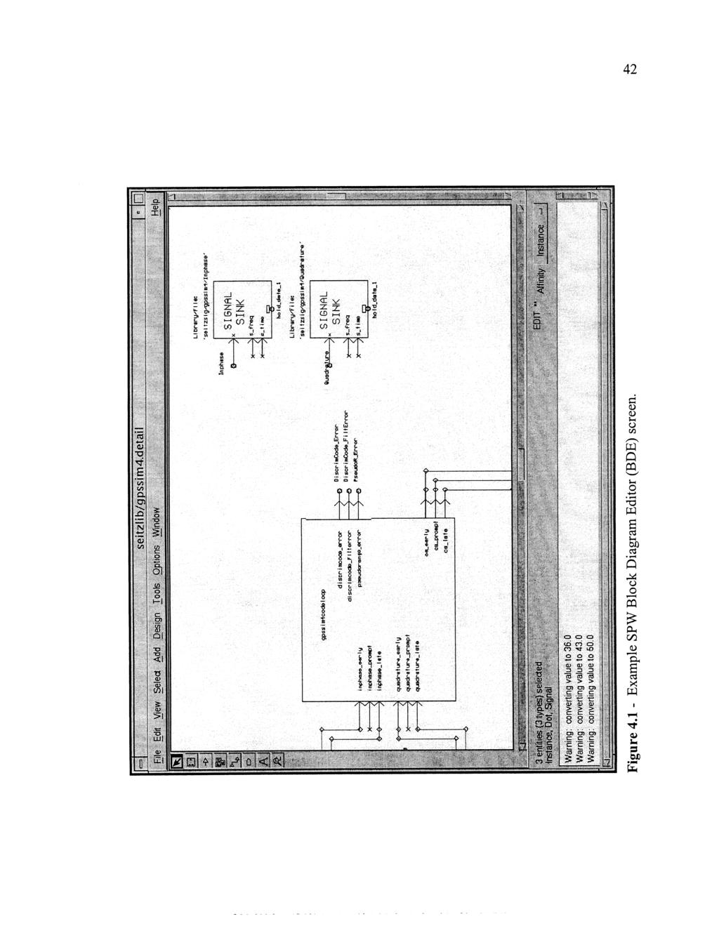
52
53 43 insert blocks both from within the SPW environment and to create user definable blocks. Each system component may have several design layers, meaning that each block may contain other blocks. Each block may be connected using a combination of wires, ports, and connectors. From here, the design may be converted into a sub-system block for use in a larger system, or may be executed using the SPW simulation tools. SigCalc is a signal analysis component within the SPW environment. Blocks are available within the BDE software component to generate and store signals. The SigCalc program is used to manipulate and view these signals. Also, SigCalc can be used to generate signals using built-in function generators such as sinusoidal waves and random processes. Some of the mathematical features within SigCalc are simple math functions such as addition/multiplication, Fourier techniques, and sarnplinglfiltering functions. Figure 4.2 shows an example SigCalc screen. Another important piece of the SPW software is the Simulation Manager. The simulation manager is responsible for executing a block diagram in a simulation environment and is shown in Figure 4.3. The user created block diagrams contain components that generate samples. These samples are passed throughout the block diagram and are manipulated by other system components. The Simulution Manager is responsible for administering the samples that are passed throughout the system. There are several different ways that a user simulation may be executed. The first method uses the SPW-I simulation language. This is a simulation process that breaks up the block diagram into network listings that may be executed using an internal SPW simulation interpreter. The second method is called SPW-C and is an optional SPW component called Code Generation System (CGS). This component generates,

54 Figure Example SPW Signal Calculator (SigCalc) screen.

55 Figure Example SPW simulation manager screen.
Satellite Navigation Principle and performance of GPS receivers
 Satellite Navigation Principle and performance of GPS receivers AE4E08 GPS Block IIF satellite Boeing North America Christian Tiberius Course 2010 2011, lecture 3 Today s topics Introduction basic idea
Spread Spectrum Techniques
 0 Spread Spectrum Techniques Contents 1 1. Overview 2. Pseudonoise Sequences 3. Direct Sequence Spread Spectrum Systems 4. Frequency Hopping Systems 5. Synchronization 6. Applications 2 1. Overview Basic
GNSS Technologies. GNSS Acquisition Dr. Zahidul Bhuiyan Finnish Geospatial Research Institute, National Land Survey
 GNSS Acquisition 25.1.2016 Dr. Zahidul Bhuiyan Finnish Geospatial Research Institute, National Land Survey Content GNSS signal background Binary phase shift keying (BPSK) modulation Binary offset carrier
Lecture 9: Spread Spectrum Modulation Techniques
 Lecture 9: Spread Spectrum Modulation Techniques Spread spectrum (SS) modulation techniques employ a transmission bandwidth which is several orders of magnitude greater than the minimum required bandwidth
LOW POWER GLOBAL NAVIGATION SATELLITE SYSTEM (GNSS) SIGNAL DETECTION AND PROCESSING
 SIGNAL DETECTION AND PROCESSING") LOW POWER GLOBAL NAVIGATION SATELLITE SYSTEM (GNSS) SIGNAL DETECTION AND PROCESSING Dennis M. Akos, Per-Ludvig Normark, Jeong-Taek Lee, Konstantin G. Gromov Stanford University James B. Y. Tsui, John Schamus
LOW POWER GLOBAL NAVIGATION SATELLITE SYSTEM (GNSS) SIGNAL DETECTION AND PROCESSING Dennis M. Akos, Per-Ludvig Normark, Jeong-Taek Lee, Konstantin G. Gromov Stanford University James B. Y. Tsui, John Schamus
GPS RECEIVER IMPLEMENTATION USING SIMULINK
 GPS RECEIVER IMPLEMENTATION USING SIMULINK C.Abhishek 1, A.Charitha 2, Dasari Goutham 3 1 Student, SCSVMV University, Kanchipuram 2 Student, kl university, Vijayawada 3 Student, SVEC college, Tirupati
QUESTION BANK EC 1351 DIGITAL COMMUNICATION YEAR / SEM : III / VI UNIT I- PULSE MODULATION PART-A (2 Marks) 1. What is the purpose of sample and hold
 1. What is the purpose of sample and hold") QUESTION BANK EC 1351 DIGITAL COMMUNICATION YEAR / SEM : III / VI UNIT I- PULSE MODULATION PART-A (2 Marks) 1. What is the purpose of sample and hold circuit 2. What is the difference between natural sampling
QUESTION BANK EC 1351 DIGITAL COMMUNICATION YEAR / SEM : III / VI UNIT I- PULSE MODULATION PART-A (2 Marks) 1. What is the purpose of sample and hold circuit 2. What is the difference between natural sampling
Analysis of Processing Parameters of GPS Signal Acquisition Scheme
 Analysis of Processing Parameters of GPS Signal Acquisition Scheme Prof. Vrushali Bhatt, Nithin Krishnan Department of Electronics and Telecommunication Thakur College of Engineering and Technology Mumbai-400101,
B SCITEQ. Transceiver and System Design for Digital Communications. Scott R. Bullock, P.E. Third Edition. SciTech Publishing, Inc.
 Transceiver and System Design for Digital Communications Scott R. Bullock, P.E. Third Edition B SCITEQ PUBLISHtN^INC. SciTech Publishing, Inc. Raleigh, NC Contents Preface xvii About the Author xxiii Transceiver
SPREAD SPECTRUM CHANNEL MEASUREMENT INSTRUMENT
 SPACE SPREAD SPECTRUM CHANNEL MEASUREMENT INSTRUMENT Satellite communications, earth observation, navigation and positioning and control stations indracompany.com SSCMI SPREAD SPECTRUM CHANNEL MEASUREMENT
Understanding GPS: Principles and Applications Second Edition
 Understanding GPS: Principles and Applications Second Edition Elliott Kaplan and Christopher Hegarty ISBN 1-58053-894-0 Approx. 680 pages Navtech Part #1024 This thoroughly updated second edition of an
GPS Receiver Architectures and Measurements
 GPS Receiver Architectures and Measurements MICHAEL S. BRAASCH, MEMBER, IEEE, AND A. J. VAN DIERENDONCK, SENIOR MEMBER, IEEE Invited Paper Although originally developed for the military, the Global Positioning
Acquisition and Tracking of IRNSS Receiver on MATLAB and Xilinx
 Acquisition and Tracking of IRNSS Receiver on MATLAB and Xilinx Kishan Y. Rathod 1, Dr. Rajendra D. Patel 2, Amit Chorasiya 3 1 M.E Student / Marwadi Education Foundation s Groups of Institute 2 Accociat
CHAPTER 2. Instructor: Mr. Abhijit Parmar Course: Mobile Computing and Wireless Communication ( )
") CHAPTER 2 Instructor: Mr. Abhijit Parmar Course: Mobile Computing and Wireless Communication (2170710) Syllabus Chapter-2.4 Spread Spectrum Spread Spectrum SS was developed initially for military and intelligence
CHAPTER 2 Instructor: Mr. Abhijit Parmar Course: Mobile Computing and Wireless Communication (2170710) Syllabus Chapter-2.4 Spread Spectrum Spread Spectrum SS was developed initially for military and intelligence
Decoding Galileo and Compass
 Decoding Galileo and Compass Grace Xingxin Gao The GPS Lab, Stanford University June 14, 2007 What is Galileo System? Global Navigation Satellite System built by European Union The first Galileo test satellite
Spread Spectrum. Chapter 18. FHSS Frequency Hopping Spread Spectrum DSSS Direct Sequence Spread Spectrum DSSS using CDMA Code Division Multiple Access
 Spread Spectrum Chapter 18 FHSS Frequency Hopping Spread Spectrum DSSS Direct Sequence Spread Spectrum DSSS using CDMA Code Division Multiple Access Single Carrier The traditional way Transmitted signal
BIT SYNCHRONIZERS FOR PSK AND THEIR DIGITAL IMPLEMENTATION
 BIT SYNCHRONIZERS FOR PSK AND THEIR DIGITAL IMPLEMENTATION Jack K. Holmes Holmes Associates, Inc. 1338 Comstock Avenue Los Angeles, California 90024 ABSTRACT Bit synchronizers play an important role in
Antenna Measurements using Modulated Signals
 Antenna Measurements using Modulated Signals Roger Dygert MI Technologies, 1125 Satellite Boulevard, Suite 100 Suwanee, GA 30024-4629 Abstract Antenna test engineers are faced with testing increasingly
GPS software receiver implementations
 GPS software receiver implementations OLEKSIY V. KORNIYENKO AND MOHAMMAD S. SHARAWI THIS ARTICLE PRESENTS A DETAILED description of the various modules needed for the implementation of a global positioning
Spread Spectrum (SS) is a means of transmission in which the signal occupies a
 is a means of transmission in which the signal occupies a") SPREAD-SPECTRUM SPECTRUM TECHNIQUES: A BRIEF OVERVIEW SS: AN OVERVIEW Spread Spectrum (SS) is a means of transmission in which the signal occupies a bandwidth in excess of the minimum necessary to send
SPREAD-SPECTRUM SPECTRUM TECHNIQUES: A BRIEF OVERVIEW SS: AN OVERVIEW Spread Spectrum (SS) is a means of transmission in which the signal occupies a bandwidth in excess of the minimum necessary to send
Mobile & Wireless Networking. Lecture 2: Wireless Transmission (2/2)
") 192620010 Mobile & Wireless Networking Lecture 2: Wireless Transmission (2/2) [Schiller, Section 2.6 & 2.7] [Reader Part 1: OFDM: An architecture for the fourth generation] Geert Heijenk Outline of Lecture
192620010 Mobile & Wireless Networking Lecture 2: Wireless Transmission (2/2) [Schiller, Section 2.6 & 2.7] [Reader Part 1: OFDM: An architecture for the fourth generation] Geert Heijenk Outline of Lecture
Signals, and Receivers
 ENGINEERING SATELLITE-BASED NAVIGATION AND TIMING Global Navigation Satellite Systems, Signals, and Receivers John W. Betz IEEE IEEE PRESS Wiley CONTENTS Preface Acknowledgments Useful Constants List of
PHASELOCK TECHNIQUES INTERSCIENCE. Third Edition. FLOYD M. GARDNER Consulting Engineer Palo Alto, California A JOHN WILEY & SONS, INC.
 PHASELOCK TECHNIQUES Third Edition FLOYD M. GARDNER Consulting Engineer Palo Alto, California INTERSCIENCE A JOHN WILEY & SONS, INC., PUBLICATION CONTENTS PREFACE NOTATION xvii xix 1 INTRODUCTION 1 1.1
QUESTION BANK SUBJECT: DIGITAL COMMUNICATION (15EC61)
") QUESTION BANK SUBJECT: DIGITAL COMMUNICATION (15EC61) Module 1 1. Explain Digital communication system with a neat block diagram. 2. What are the differences between digital and analog communication systems?
QUESTION BANK SUBJECT: DIGITAL COMMUNICATION (15EC61) Module 1 1. Explain Digital communication system with a neat block diagram. 2. What are the differences between digital and analog communication systems?
Performance of Wideband Mobile Channel with Perfect Synchronism BPSK vs QPSK DS-CDMA
 Performance of Wideband Mobile Channel with Perfect Synchronism BPSK vs QPSK DS-CDMA By Hamed D. AlSharari College of Engineering, Aljouf University, Sakaka, Aljouf 2014, Kingdom of Saudi Arabia, hamed_100@hotmail.com
Chapter 5. Clock Offset Due to Antenna Rotation
 Chapter 5. Clock Offset Due to Antenna Rotation 5. Introduction The goal of this experiment is to determine how the receiver clock offset from GPS time is affected by a rotating antenna. Because the GPS
2 INTRODUCTION TO GNSS REFLECTOMERY
 2 INTRODUCTION TO GNSS REFLECTOMERY 2.1 Introduction The use of Global Navigation Satellite Systems (GNSS) signals reflected by the sea surface for altimetry applications was first suggested by Martín-Neira
LOW DATA RATE BPSK DEMODULATION IN PRESENCE OF DOPPLER
 LOW DATA RATE BPSK DEMODULATION IN PRESENCE OF DOPPLER Aghanash Karthik 1 Ashwin.R 2, Dr.Sambasiva Rao.V 3, Prof. V. Mahadevan 4 1,2,3 Dept. of ECE, PESIT, Bangalore, 4 Dept. of TCE, PESIT, Bangalore Abstract
Exercise 3-2. Digital Modulation EXERCISE OBJECTIVE DISCUSSION OUTLINE DISCUSSION. PSK digital modulation
 Exercise 3-2 Digital Modulation EXERCISE OBJECTIVE When you have completed this exercise, you will be familiar with PSK digital modulation and with a typical QPSK modulator and demodulator. DISCUSSION
Proceedings of Al-Azhar Engineering 7 th International Conference Cairo, April 7-10, 2003.
 Proceedings of Al-Azhar Engineering 7 th International Conference Cairo, April 7-10, 2003. MODERNIZATION PLAN OF GPS IN 21 st CENTURY AND ITS IMPACTS ON SURVEYING APPLICATIONS G. M. Dawod Survey Research
GPS receivers built for various
 GNSS Solutions: Measuring GNSS Signal Strength angelo joseph GNSS Solutions is a regular column featuring questions and answers about technical aspects of GNSS. Readers are invited to send their questions
UNIT 1 - introduction to GPS
 UNIT 1 - introduction to GPS 1. GPS SIGNAL Each GPS satellite transmit two signal for positioning purposes: L1 signal (carrier frequency of 1,575.42 MHz). Modulated onto the L1 carrier are two pseudorandom
Downloaded from 1
 VII SEMESTER FINAL EXAMINATION-2004 Attempt ALL questions. Q. [1] How does Digital communication System differ from Analog systems? Draw functional block diagram of DCS and explain the significance of
CDMA Mobile Radio Networks
 - 1 - CDMA Mobile Radio Networks Elvino S. Sousa Department of Electrical and Computer Engineering University of Toronto Canada ECE1543S - Spring 1999 - 2 - CONTENTS Basic principle of direct sequence
Research on DQPSK Carrier Synchronization based on FPGA
 Journal of Information Hiding and Multimedia Signal Processing c 27 ISSN 273-422 Ubiquitous International Volume 8, Number, January 27 Research on DQPSK Carrier Synchronization based on FPGA Shi-Jun Kang,
International Journal of ISSN Systems and Technologies Vol.3, No.1, pp IJST KLEF 2010
 International Journal of ISSN 0974-2107 Systems and Technologies Vol.3, No.1, pp 127-137 IJST KLEF 2010 Use of Two-Way CDMA Ranging for Precise Orbit Determination of IRNSS Satellites T.Subramanya Ganesh
Laboratory 5: Spread Spectrum Communications
 Laboratory 5: Spread Spectrum Communications Cory J. Prust, Ph.D. Electrical Engineering and Computer Science Department Milwaukee School of Engineering Last Update: 19 September 2018 Contents 0 Laboratory
MODULATION AND MULTIPLE ACCESS TECHNIQUES
 1 MODULATION AND MULTIPLE ACCESS TECHNIQUES Networks and Communication Department Dr. Marwah Ahmed Outlines 2 Introduction Digital Transmission Digital Modulation Digital Transmission of Analog Signal
ECS455: Chapter 4 Multiple Access
 ECS455: Chapter 4 Multiple Access 4.9 Async. CDMA: Gold codes and GPS 1 Dr.Prapun Suksompong prapun.com/ecs455 Office Hours: BKD 3601-7 Tuesday 9:30-10:30 Tuesday 13:30-14:30 Thursday 13:30-14:30 Asynchronous
EE 400L Communications. Laboratory Exercise #7 Digital Modulation
 EE 400L Communications Laboratory Exercise #7 Digital Modulation Department of Electrical and Computer Engineering University of Nevada, at Las Vegas PREPARATION 1- ASK Amplitude shift keying - ASK - in
t =1 Transmitter #2 Figure 1-1 One Way Ranging Schematic
 1.0 Introduction OpenSource GPS is open source software that runs a GPS receiver based on the Zarlink GP2015 / GP2021 front end and digital processing chipset. It is a fully functional GPS receiver which
Fundamentals of Digital Communication
 Fundamentals of Digital Communication Network Infrastructures A.A. 2017/18 Digital communication system Analog Digital Input Signal Analog/ Digital Low Pass Filter Sampler Quantizer Source Encoder Channel
Evaluation of C/N 0 estimators performance for GNSS receivers
 International Conference and Exhibition The 14th IAIN Congress 2012 Seamless Navigation (Challenges & Opportunities) 01-03 October, 2012 - Cairo, Egypt Concorde EL Salam Hotel Evaluation of C/N 0 estimators
Amplitude and Phase Distortions in MIMO and Diversity Systems
 Amplitude and Phase Distortions in MIMO and Diversity Systems Christiane Kuhnert, Gerd Saala, Christian Waldschmidt, Werner Wiesbeck Institut für Höchstfrequenztechnik und Elektronik (IHE) Universität
CARRIER PHASE VS. CODE PHASE
 DIFFERENTIAL CORRECTION Code phase processing- GPS measurements based on the pseudo random code (C/A or P) as opposed to the carrier of that code. (1-5 meter accuracy) Carrier phase processing- GPS measurements
A Survey on SQM for Sat-Nav Systems
 A Survey on SQM for Sat-Nav Systems Sudarshan Bharadwaj DS Department of ECE, Cambridge Institute of Technology, Bangalore Abstract: Reduction of multipath effects on the satellite signals can be accomplished
Making Noise in RF Receivers Simulate Real-World Signals with Signal Generators
 Making Noise in RF Receivers Simulate Real-World Signals with Signal Generators Noise is an unwanted signal. In communication systems, noise affects both transmitter and receiver performance. It degrades
Lab 3.0. Pulse Shaping and Rayleigh Channel. Faculty of Information Engineering & Technology. The Communications Department
 Faculty of Information Engineering & Technology The Communications Department Course: Advanced Communication Lab [COMM 1005] Lab 3.0 Pulse Shaping and Rayleigh Channel 1 TABLE OF CONTENTS 2 Summary...
Phase-Locked Loops. Roland E. Best. Me Graw Hill. Sixth Edition. Design, Simulation, and Applications
 Phase-Locked Loops Design, Simulation, and Applications Roland E. Best Sixth Edition Me Graw Hill New York Chicago San Francisco Lisbon London Madrid Mexico City Milan New Delhi San Juan Seoul Singapore
OHIO UNIVERSITY LIBRARY
 MULTIPATH ERRORS INDUCED BY ELECTRONIC COMPONENTS IN RECEIVER HARD WARE A Thesis Presented to The Faculty of the Fritz J. and Dolores H. Russ College of Engineering and Technology Ohio University In Partial
SPREAD SPECTRUM (SS) SIGNALS FOR DIGITAL COMMUNICATIONS
 SIGNALS FOR DIGITAL COMMUNICATIONS") Dr. Ali Muqaibel SPREAD SPECTRUM (SS) SIGNALS FOR DIGITAL COMMUNICATIONS VERSION 1.1 Dr. Ali Hussein Muqaibel 1 Introduction Narrow band signal (data) In Spread Spectrum, the bandwidth W is much greater
Dr. Ali Muqaibel SPREAD SPECTRUM (SS) SIGNALS FOR DIGITAL COMMUNICATIONS VERSION 1.1 Dr. Ali Hussein Muqaibel 1 Introduction Narrow band signal (data) In Spread Spectrum, the bandwidth W is much greater
Antennas and Propagation
 Antennas and Propagation Chapter 5 Introduction An antenna is an electrical conductor or system of conductors Transmission - radiates electromagnetic energy into space Reception - collects electromagnetic
Introduction to Global Navigation Satellite System (GNSS) Signal Structure
 Signal Structure") Introduction to Global Navigation Satellite System (GNSS) Signal Structure Dinesh Manandhar Center for Spatial Information Science The University of Tokyo Contact Information: dinesh@iis.u-tokyo.ac.jp
Introduction to Global Navigation Satellite System (GNSS) Signal Structure Dinesh Manandhar Center for Spatial Information Science The University of Tokyo Contact Information: dinesh@iis.u-tokyo.ac.jp
Vector tracking loops are a type
 GNSS Solutions: What are vector tracking loops, and what are their benefits and drawbacks? GNSS Solutions is a regular column featuring questions and answers about technical aspects of GNSS. Readers are
Signals and Systems Lecture 9 Communication Systems Frequency-Division Multiplexing and Frequency Modulation (FM)
") Signals and Systems Lecture 9 Communication Systems Frequency-Division Multiplexing and Frequency Modulation (FM) April 11, 2008 Today s Topics 1. Frequency-division multiplexing 2. Frequency modulation
Signals and Systems Lecture 9 Communication Systems Frequency-Division Multiplexing and Frequency Modulation (FM) April 11, 2008 Today s Topics 1. Frequency-division multiplexing 2. Frequency modulation
Lecture 6. Angle Modulation and Demodulation
 Lecture 6 and Demodulation Agenda Introduction to and Demodulation Frequency and Phase Modulation Angle Demodulation FM Applications Introduction The other two parameters (frequency and phase) of the carrier
two computers. 2- Providing a channel between them for transmitting and receiving the signals through it.
 1. Introduction: Communication is the process of transmitting the messages that carrying information, where the two computers can be communicated with each other if the two conditions are available: 1-
Antennas and Propagation
 Mobile Networks Module D-1 Antennas and Propagation 1. Introduction 2. Propagation modes 3. Line-of-sight transmission 4. Fading Slides adapted from Stallings, Wireless Communications & Networks, Second
Understanding GPS/GNSS
 Understanding GPS/GNSS Principles and Applications Third Edition Contents Preface to the Third Edition Third Edition Acknowledgments xix xxi CHAPTER 1 Introduction 1 1.1 Introduction 1 1.2 GNSS Overview
GPS and Recent Alternatives for Localisation. Dr. Thierry Peynot Australian Centre for Field Robotics The University of Sydney
 GPS and Recent Alternatives for Localisation Dr. Thierry Peynot Australian Centre for Field Robotics The University of Sydney Global Positioning System (GPS) All-weather and continuous signal system designed
Update on GPS L1C Signal Modernization. Tom Stansell Aerospace Consultant GPS Wing
 Update on GPS L1C Signal Modernization Tom Stansell Aerospace Consultant GPS Wing Glossary BOC = Binary Offset Carrier modulation C/A = GPS Coarse/Acquisition code dbw = 10 x log(signal Power/1 Watt) E1
THE DESIGN OF C/A CODE GLONASS RECEIVER
 THE DESIGN OF C/A CODE GLONASS RECEIVER Liu Hui Cheng Leelung Zhang Qishan ABSTRACT GLONASS is similar to GPS in many aspects such as system configuration, navigation mechanism, signal structure, etc..
CDMA Principle and Measurement
 CDMA Principle and Measurement Concepts of CDMA CDMA Key Technologies CDMA Air Interface CDMA Measurement Basic Agilent Restricted Page 1 Cellular Access Methods Power Time Power Time FDMA Frequency Power
Multiple Reference Clock Generator
 A White Paper Presented by IPextreme Multiple Reference Clock Generator Digitial IP for Clock Synthesis August 2007 IPextreme, Inc. This paper explains the concept behind the Multiple Reference Clock Generator
Chapter 4. Part 2(a) Digital Modulation Techniques
 Digital Modulation Techniques") Chapter 4 Part 2(a) Digital Modulation Techniques Overview Digital Modulation techniques Bandpass data transmission Amplitude Shift Keying (ASK) Phase Shift Keying (PSK) Frequency Shift Keying (FSK) Quadrature
Chapter 4 Part 2(a) Digital Modulation Techniques Overview Digital Modulation techniques Bandpass data transmission Amplitude Shift Keying (ASK) Phase Shift Keying (PSK) Frequency Shift Keying (FSK) Quadrature
TEST RESULTS OF A HIGH GAIN ADVANCED GPS RECEIVER
 TEST RESULTS OF A HIGH GAIN ADVANCED GPS RECEIVER ABSTRACT Dr. Alison Brown, Randy Silva, Gengsheng Zhang,; NAVSYS Corporation. NAVSYS High Gain Advanced GPS Receiver () uses a digital beam-steering antenna
GPS Global Positioning System
 GPS Global Positioning System 10.04.2012 1 Agenda What is GPS? Basic consept History GPS receivers How they work Comunication Message format Satellite frequencies Sources of GPS signal errors 10.04.2012
POWERGPS : A New Family of High Precision GPS Products
 POWERGPS : A New Family of High Precision GPS Products Hiroshi Okamoto and Kazunori Miyahara, Sokkia Corp. Ron Hatch and Tenny Sharpe, NAVCOM Technology Inc. BIOGRAPHY Mr. Okamoto is the Manager of Research
Design and Implementation of a SoC-Based Real-Time Vector Tracking GPS Receiver. Brian A. Keyser
 Design and Implementation of a SoC-Based Real-Time Vector Tracking GPS Receiver by Brian A. Keyser A thesis submitted to the Graduate Faculty of Auburn University in partial fulfillment of the requirements
REAL-TIME IMPLEMENTATION AND ANALYSIS OF CHIP SHAPE-BASED SOFTWARE DEFINED RECEIVER
 REAL-TIME IMPLEMENTATION AND ANALYSIS OF CHIP SHAPE-BASED SOFTWARE DEFINED RECEIVER Thesis Submitted to The School of Engineering of the UNIVERSITY OF DAYTON In Partial Fulfillment of the Requirements
HIGH GAIN ADVANCED GPS RECEIVER
 ABSTRACT HIGH GAIN ADVANCED GPS RECEIVER NAVSYS High Gain Advanced () uses a digital beam-steering antenna array to enable up to eight GPS satellites to be tracked, each with up to dbi of additional antenna
Phase-Locked Loop Engineering Handbook for Integrated Circuits
 Phase-Locked Loop Engineering Handbook for Integrated Circuits Stanley Goldman ARTECH H O U S E BOSTON LONDON artechhouse.com Preface Acknowledgments xiii xxi CHAPTER 1 Cetting Started with PLLs 1 1.1
Chapter 2 Direct-Sequence Systems
 Chapter 2 Direct-Sequence Systems A spread-spectrum signal is one with an extra modulation that expands the signal bandwidth greatly beyond what is required by the underlying coded-data modulation. Spread-spectrum
4-2 Development of Two-Way Time and Frequency Transfer System with Dual Pseudo Random Noises
 4- Development of Two-Way Time and Frequency Transfer System with Dual Pseudo Random Noises We developed Two-Way Satellite Time and Frequency Transfer with Dual Pseudo Random Noises as a method to improve
Amplitude Frequency Phase
 Chapter 4 (part 2) Digital Modulation Techniques Chapter 4 (part 2) Overview Digital Modulation techniques (part 2) Bandpass data transmission Amplitude Shift Keying (ASK) Phase Shift Keying (PSK) Frequency
Spread Spectrum: Definition
 Spread Spectrum: Definition refers to the expansion of signal bandwidth, by several orders of magnitude in some cases, which occurs when a key is attached to the communication channel an RF communications
0.6 kbits/s, the modulation shall be aviation binary phase shift keying (A-BPSK).
.") SECTION 3 RF CHANNEL CHARACTERISTICS 3.1 Modulation 3.1.1 Modulation for channel rates 2.4 kbits/s and below. For channel rates of 2.4, 1.2 and 0.6 kbits/s, the modulation shall be aviation binary phase
SECTION 3 RF CHANNEL CHARACTERISTICS 3.1 Modulation 3.1.1 Modulation for channel rates 2.4 kbits/s and below. For channel rates of 2.4, 1.2 and 0.6 kbits/s, the modulation shall be aviation binary phase
Digital modulation techniques
 Outline Introduction Signal, random variable, random process and spectra Analog modulation Analog to digital conversion Digital transmission through baseband channels Signal space representation Optimal
Part A: Spread Spectrum Systems
 1 Telecommunication Systems and Applications (TL - 424) Part A: Spread Spectrum Systems Dr. ir. Muhammad Nasir KHAN Department of Electrical Engineering Swedish College of Engineering and Technology March
BER Calculation of DS-CDMA over Communication Channels
 BER Calculation of DS-CDMA over Communication Channels Dr. Saroj Choudhary A, Purneshwari Varshney B A Associate Professor, Department of Applied Science, Jodhpur National University, Jodhpur, Rajasthan,
COMMUNICATION SYSTEMS
 COMMUNICATION SYSTEMS 4TH EDITION Simon Hayhin McMaster University JOHN WILEY & SONS, INC. Ш.! [ BACKGROUND AND PREVIEW 1. The Communication Process 1 2. Primary Communication Resources 3 3. Sources of
Session2 Antennas and Propagation
 Wireless Communication Presented by Dr. Mahmoud Daneshvar Session2 Antennas and Propagation 1. Introduction Types of Anttenas Free space Propagation 2. Propagation modes 3. Transmission Problems 4. Fading
EE 460L University of Nevada, Las Vegas ECE Department
 EE 460L PREPARATION 1- ASK Amplitude shift keying - ASK - in the context of digital communications is a modulation process which imparts to a sinusoid two or more discrete amplitude levels. These are related
satellite terminals. Mr. Murray is with the Time and Frequency Systems Unit, Naval Research Laboratory, Washington, D.C.
 MN MODEM FOR PTT DSSEMNATON by J. A. Murray, Jr. Mr. Murray is with the Time and Frequency Systems Unit, Naval Research Laboratory, Washington, D.C. Precise comparisons of clocks are now regularly made
Outline / Wireless Networks and Applications Lecture 3: Physical Layer Signals, Modulation, Multiplexing. Cartoon View 1 A Wave of Energy
 Outline 18-452/18-750 Wireless Networks and Applications Lecture 3: Physical Layer Signals, Modulation, Multiplexing Peter Steenkiste Carnegie Mellon University Spring Semester 2017 http://www.cs.cmu.edu/~prs/wirelesss17/
Thus there are three basic modulation techniques: 1) AMPLITUDE SHIFT KEYING 2) FREQUENCY SHIFT KEYING 3) PHASE SHIFT KEYING
 AMPLITUDE SHIFT KEYING 2) FREQUENCY SHIFT KEYING 3) PHASE SHIFT KEYING") CHAPTER 5 Syllabus 1) Digital modulation formats 2) Coherent binary modulation techniques 3) Coherent Quadrature modulation techniques 4) Non coherent binary modulation techniques. Digital modulation formats:
CHAPTER 5 Syllabus 1) Digital modulation formats 2) Coherent binary modulation techniques 3) Coherent Quadrature modulation techniques 4) Non coherent binary modulation techniques. Digital modulation formats:
Chapter 2 Channel Equalization
 Chapter 2 Channel Equalization 2.1 Introduction In wireless communication systems signal experiences distortion due to fading [17]. As signal propagates, it follows multiple paths between transmitter and
Performance Comparison of RAKE and Hypothesis Feedback Direct Sequence Spread Spectrum Techniques for Underwater Communication Applications
 Performance Comparison of RAKE and Hypothesis Feedback Direct Sequence Spread Spectrum Techniques for Underwater Communication Applications F. Blackmon, E. Sozer, M. Stojanovic J. Proakis, Naval Undersea
CHAPTER. delta-sigma modulators 1.0
 CHAPTER 1 CHAPTER Conventional delta-sigma modulators 1.0 This Chapter presents the traditional first- and second-order DSM. The main sources for non-ideal operation are described together with some commonly
DSRC using OFDM for roadside-vehicle communication systems
 DSRC using OFDM for roadside-vehicle communication systems Akihiro Kamemura, Takashi Maehata SUMITOMO ELECTRIC INDUSTRIES, LTD. Phone: +81 6 6466 5644, Fax: +81 6 6462 4586 e-mail:kamemura@rrad.sei.co.jp,
THIS work focus on a sector of the hardware to be used
 DISSERTATION ON ELECTRICAL AND COMPUTER ENGINEERING 1 Development of a Transponder for the ISTNanoSAT (November 2015) Luís Oliveira luisdeoliveira@tecnico.ulisboa.pt Instituto Superior Técnico Abstract
Presentation Outline. Advisors: Dr. In Soo Ahn Dr. Thomas L. Stewart. Team Members: Luke Vercimak Karl Weyeneth. Karl. Luke
 Bradley University Department of Electrical and Computer Engineering Senior Capstone Project Presentation May 2nd, 2006 Team Members: Luke Vercimak Karl Weyeneth Advisors: Dr. In Soo Ahn Dr. Thomas L.
Second Workshop on Satellite Navigation Science and Technology for Africa April 2010
 2135-1 Second Workshop on Satellite Navigation Science and Technology for Africa 6-23 April 2010 GPS Receivers, Receiver Signals and Principals of Operation Phillip W. Ward NavWard Consultants Garland,
Time division multiplexing The block diagram for TDM is illustrated as shown in the figure
 CHAPTER 2 Syllabus: 1) Pulse amplitude modulation 2) TDM 3) Wave form coding techniques 4) PCM 5) Quantization noise and SNR 6) Robust quantization Pulse amplitude modulation In pulse amplitude modulation,
The Radio Channel. COS 463: Wireless Networks Lecture 14 Kyle Jamieson. [Parts adapted from I. Darwazeh, A. Goldsmith, T. Rappaport, P.
 The Radio Channel COS 463: Wireless Networks Lecture 14 Kyle Jamieson [Parts adapted from I. Darwazeh, A. Goldsmith, T. Rappaport, P. Steenkiste] Motivation The radio channel is what limits most radio
PERFORMANCE ANALYSIS OF DIFFERENT M-ARY MODULATION TECHNIQUES IN FADING CHANNELS USING DIFFERENT DIVERSITY
 PERFORMANCE ANALYSIS OF DIFFERENT M-ARY MODULATION TECHNIQUES IN FADING CHANNELS USING DIFFERENT DIVERSITY 1 MOHAMMAD RIAZ AHMED, 1 MD.RUMEN AHMED, 1 MD.RUHUL AMIN ROBIN, 1 MD.ASADUZZAMAN, 2 MD.MAHBUB
EXPERIMENT WISE VIVA QUESTIONS
 EXPERIMENT WISE VIVA QUESTIONS Pulse Code Modulation: 1. Draw the block diagram of basic digital communication system. How it is different from analog communication system. 2. What are the advantages of
Monitoring Station for GNSS and SBAS
 Monitoring Station for GNSS and SBAS Pavel Kovář, Czech Technical University in Prague Josef Špaček, Czech Technical University in Prague Libor Seidl, Czech Technical University in Prague Pavel Puričer,
Utilizing Batch Processing for GNSS Signal Tracking
 Utilizing Batch Processing for GNSS Signal Tracking Andrey Soloviev Avionics Engineering Center, Ohio University Presented to: ION Alberta Section, Calgary, Canada February 27, 2007 Motivation: Outline
Design and Implementation of Real Time Basic GPS Receiver System using Simulink 8.1
 Design and Implementation of Real Time Basic GPS Receiver System using Simulink 8.1 Mrs. Rachna Kumari 1, Dr. Mainak Mukhopadhyay 2 1 Research Scholar, Birla Institute of Technology, Mesra, Jharkhand,