|
|
|
- Alexander Brown
- 5 years ago
- Views:
Transcription


1

2

3


4

5

6


7
8

9


10


11 Exhibit A Proposal for Aerial Services Champaign and Piatt Counties, Illinois Issue Date: Monday, October 31, 2016 Proposal Due: 11:30 am Wednesday, November 30, 2016
12 1.0 Introduction Scope of Work Options Acquisition of Aerial Imagery Flight Specifications Digital Aerial Camera Flying Height Flight Planning Stereo Images Aerial Imagery Review Camera Station Control Supplemental Ground Control Digital Ortho-Imagery Production Digital Elevation Model Aerotriangulation Digital Ortho-imagery Non-Image Data Deliverables Quality Control of Deliverables Contractor Responsibilities Suggestions or Modifications to the Scope of Work Proposal Format / Requirements Proposal Submittal Proposal Evaluation General Information and Requirements Attachment A Attachment B Attachment C Champaign County GIS Consortium Digital Color Ortho-imagery Acquisition 2017 Page 1
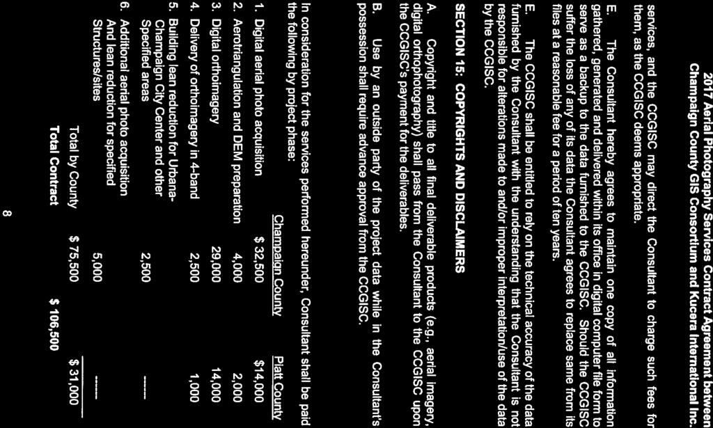
13 1.0 Introduction The Champaign County GIS Consortium (CCGISC), acting as the administrative agent for Champaign County and Piatt County solicits qualified and interested firms to submit proposals for providing the services, supervision, labor, equipment, products and materials necessary to provide digital orthoimagery services for areas within Champaign and Piatt counties as described in and meeting the specifications of the Scope of Work. The imagery and related products will be used within a GIS for parcel, infrastructure, and other mapping. Ortho-photography was last acquired for these counties in Champaign and Piatt counties are located about 135 miles south of Chicago, in the heart of East- Central Illinois. Champaign County was incorporated in 1833 and is approximately 1000 square miles in area, with a population of 201,081 (2010 census estimate). Approximately two-thirds of Champaign County s population lives within a 140 square mile area that surrounds the Cities of Champaign and Urbana, the Village of Mahomet, and the Village of Savoy. Piatt County was incorporated in 1841 and is approximately 450 square miles in area, with a population of 16,729 (2010 census estimate). The largest community in Piatt County is Monticello with a population of approximately 5,500. This RFP does not commit CCGISC, Champaign County, or Piatt County to award a contract or pay for any costs incurred in the preparation of a proposal. CCGISC reserves the right to accept or reject any or all proposals received, or to cancel, in part or in whole, this RFP. 2.0 Scope of Work The Champaign County GIS Consortium is interested in acquiring natural color aerial imagery for Champaign and Piatt counties. The aerial imagery is to be processed to produce ortho-imagery. The CCGISC is soliciting bids for 6-inch resolution ortho-imagery covering a 1694 square-mile contiguous area (Piatt 546 square-miles; Champaign 1148 square-miles). 2.1 Options All bids need to include costs for the following options. OPTION 1: Standard 6-inch resolution ortho-imagery covering a 1694 square-mile contiguous area. (Piatt 546 square-miles; Champaign 1148 square-miles) OPTION 2: 6-inch resolution ortho-imagery covering a 1694 square-mile contiguous area (Piatt 546 square-miles; Champaign 1148 square-miles) with reduced building lean in the specified Urbana-Champaign city centers (approximately 1.85 square miles). OPTION 3: 6-inch resolution ortho-imagery covering a 1694 square-mile contiguous area (Piatt 546 square-miles; Champaign 1148 square-miles) with building lean eliminated in specified areas. OPTION 4: 6-inch resolution ortho-imagery covering a 1694 square-mile contiguous area (Piatt 546 square-miles; Champaign 1148 square-miles) with reduced building lean in the specified Urbana-Champaign city centers and building lean eliminated in specified areas. See Attachment A and B for illustrations of Options 1, 2, 3, and 4. CCGISC will determine which, if any, option to proceed forward with based on the provided responses. Champaign County GIS Consortium Digital Color Ortho-imagery Acquisition 2017 Page 2
14 The resulting product is to meet the specifications as described herein. 2.2 Acquisition of Aerial Imagery The Contractor shall adhere to the following specifications for the acquisition and delivery of the requested natural-color aerial imagery Coordinate System and Datum All data shall be geo-referenced to the Illinois State Plane Coordinates, East Zone, US Survey Feet on the North American Datum (NAD) 1983 horizontal datum (2011 adjustment), and North American Vertical Datum (NAVD) Flight Specifications Imagery shall be flown when deciduous foliage is under leaf-off conditions. The target flight window shall be within February 27, 2017 and April 4, 2017, or as otherwise specified by CCGISC. The sun angle for all flights shall be at least (30) degrees above horizon. In no case shall imagery be captured when the ground is obscured by haze, snow, fog, smoke, light streaks or dust. Aerial imagery shall be flown when streams are in their normal banks and there is no evidence of temporary standing water or excessive soil moisture. The imagery shall be free of clouds and cloud shadows, and be clear, sharp, and evenly exposed. Photographs shall not contain objectionable shadows caused by building relief or low solar altitude. All airborne equipment must be properly installed and mounted in aircrafts that provide a stable aerial photography platform. These aircrafts must be properly maintained, registered, and operated according to the rules and regulations of the Federal Aviation Administration (FAA) Digital Aerial Camera The aerial camera shall be a large format precision digital camera equipped with low distortion, high-resolution optics, high geometric accuracy and forward motion compensation, and an airborne GPS and Inertial Measuring Unit (IMU). It must be capable of: Obtaining ground resolution better than 0.25-foot. Generating three-band imagery from separate co-registered red, green, and blue bands. Supporting high geometric accuracy and forward motion compensation. The successful Contractor must provide the most recent calibration report for the digital sensor Flying Height The aerial acquisition flying height shall be capable of achieving a native ground sample distance of less than 0.5-foot to produce an output resolution of 0.5-foot. Flight height shall be appropriate for the generation of 1:1,200 scale (1"=100') ortho-imagery that shall meet or exceed the American Society of Photogrammetry and Remote Sensing (ASPRS) class 1 standard at 1:1,200-scale. Proposed flying height shall be provided by the Contractor. Champaign County GIS Consortium Digital Color Ortho-imagery Acquisition 2017 Page 3
15 2.2.5 Flight Planning A flight map shall be submitted for the given project area prior to acquisition. Flight line features shall be attributed with appropriate identification information including project boundary, line numbers, exposure stations, and ground control locations. It is suggested both denser flight lines and perpendicular flight lines be used for option 2, 3 and 4. It is expected that images with reduced and/or eliminated building lean shall be incorporated into the final deliverable. The aerial mission shall be flown with coverage extending beyond the project boundary to ensure adequate coverage. All flight lines shall extend one full photo base beyond each end boundary, and all side boundaries shall be covered by a minimum of 25% of the photo image format. The Contractor shall provide a map of proposed flight lines for options 1 through 4 in their response Stereo Images Overlapping images in each flight line and between flight lines shall provide full stereoscopic coverage of the area to be mapped. Appropriate endlap and sidelap along with adjustment for crab and tilt shall be accounted for to meet output specification options 1, 2, 3, and 4. It is suggested a minimum of 60% sidelap and 80% endlap be used for options 2, 3 and 4. The Contractor shall provide proposed percentages of endlap and sidelap in their response as well as proposed tolerances for crab and camera tilt. The Contractor shall explain the proposed method that will be used to reduce/eliminate building lean (options 2, 3 and 4) in the specified areas (Attachment B) Aerial Imagery Review Contractor shall review the processed digital frames for the following: Adherence to the flight plan Ground Sample Distance Density Contrast Hot spots Clarity Shadow detail Overall quality In addition, within 4-6 weeks of the aerial flight, the Contractor shall deliver on portable USB2 external hard drives the RAW images of the aerial flight for initial photo checking. Unacceptable aerial imagery shall be corrected at no additional cost to the CCGISC. Champaign County GIS Consortium Digital Color Ortho-imagery Acquisition 2017 Page 4
16 2.2.8 Camera Station Control Airborne GPS (AGPS) - latitude, longitude and altitude - and Inertial Measurement Unit (IMU) - attitude and velocity - data shall be recorded at the instant of exposure. An AGPS/IMU data capture solution shall follow the necessary industry acceptable standards to meet the specifications as described in this Scope of Work. Geodetic positions corresponding to the photo centers at the instant of exposure shall be calculated and combined with supplemental ground control point values in an analytical aerotriangulation solution. The horizontal root-mean-square error (RMSE) shall be based on industry acceptable standards for the specified mapping scale. The contractor shall use tightly coupled AGPS/IMU collection techniques that provide high accuracy camera station coordinates. It is suggested that during the acquisition of the imagery, dual frequency GPS receivers shall be referenced to at least two reference stations. The Contractor shall produce a statistical report summarizing the results of the airborne GPS/IMU adjustment Supplemental Ground Control Surveyed ground control shall be used to support the production and meet the accuracy standards of ortho-imagery as described herein. The CCGISC will provide a Registered Professional Land Surveyor (PLS) licensed by the State of Illinois for the capture of supplemental ground control. The Contractor will be required to coordinate the needed work with the PLS supplied by CCGISC. The capture of supplemental control needs to begin by January 1, The cost of the PLS will not be incurred by the Contractor, however, the contractor will be responsible for placing any panels if needed. 2.3 Digital Ortho-Imagery Production Digital Elevation Model To support the production of the ortho-imagery, the CCGISC shall provide the Contractor with a 2008 Digital Elevation Model (DEM) that has a vertical accuracy better than 2-feet. The DEM will contain at least 4-foot horizontal spacing Aerotriangulation The Contractor shall document the used aerotriangulation process/methods and deliver a report of the analytical aerotriangulation results. Coordinates and residual values shall be reported for all points. RMSE values shall be completed and reported for the final adjustment. Discarded points shall be noted and discussed. CHECKPOINTS The calculation of the positional values (x,y,z) for the independent checkpoints shall be used for NSSDA product accuracy reporting. The CCGISC will provide a Registered Professional Land Surveyor (PLS) licensed by the State of Illinois for the capture of checkpoints. The cost of the PLS will not be incurred by the Contractor. The placement of any required panels will be the responsibility of the Contractor and the Contractor will be required to coordinate the needed work with the PLS. Checkpoint capture Champaign County GIS Consortium Digital Color Ortho-imagery Acquisition 2017 Page 5
17 must begin no later than the first week in April, 2017 to provide enough time for the PLS to complete capture by the first week in May, Digital Ortho-imagery Digital ortho-imagery shall be produced from the processed digital aerial imagery. Each processed image (raster file) shall be geo-referenced to simulate its position in space at the time of exposure. The DEM shall be applied to the raster file to rectify the image to eliminate distortion. The rectification process shall involve the solution of the appropriate photogrammetric equations for each pixel in the output image. Solution of photogrammetric equations at anchor points only, and warping the content of the original image between anchor points (rubber-sheeting) shall not be permitted. All ortho-imagery shall be edge-matched, radiometrically corrected, and color balanced. Once the imagery has been processed, it shall be structured and formatted in a seamless image database and sampled to the final output resolution of 0.5-foot ground sample distance. Reduced and/or eliminated building lean tiles (options 2, 3, and 4) shall be incorporated into the final deliverable. RADIOMETRIC CHARACTERISTICS All orthophotos shall be composed of three (3) R,G,B spectral bands: Red (R), Green (G), and Blue (B). The radiometric resolution of each band shall be eight (8) bits at minimum, where the image brightness for each band is represented by 256 levels, ranging from 0 to 255. IMAGE QUALITY Orthophotos shall not contain defects such as out-of-focus imagery, marks, scratches, or inconsistencies in tone and density between individual orthophotos. Radiometric Distortion: The Contractor shall correct distortions caused by elevated or depressed structures such as bridges, rail beds, overpasses, and steep terrain. The CCGISC shall reject any image that contains these types of distortions. Image Mosaicking: Where two or more digital orthophoto images are mosaicked, the image judged to have the best contrast shall be used as the reference image. All other images shall have their brightness values adjusted to that of the reference image. Join lines between overlapping images shall be chosen so as to minimize tonal variations. Localized adjustment of the brightness values shall be performed to minimize tonal differences between join areas. Visible seams or sutures within a digital orthophoto which exhibit a noticeable edge or feather effect shall be grounds for rejection of that digital orthophoto. Edge-Matching: All tiles shall not have more than 3 pixels offset between the principal tiles. Band to Band Registration: Misalignment between any color bands shall not exceed 1 pixel. Champaign County GIS Consortium Digital Color Ortho-imagery Acquisition 2017 Page 6
18 TILING SCHEME AND NAME The Contractor shall deliver the GeoTIFF images and associated TFW files perfectly aligned with and named according to the provided 2,500 feet x 2,500 feet index grid. DATA DELIVERY All ortho-imagery shall be delivered on USB2 external hard drive(s). Each drive shall contain the following reference information: Identification number Our name - Champaign County GIS Consortium Consultant name Date of delivery Listing of tiles PRODUCT ACCURACY AND PRODUCT ACCURACY REPORTING All inputs and processes such as aerotriangulation, control, general methodologies, and sensor calibrations used in the production of digital ortho-imagery shall be sufficient to ensure that all final digital orthoimagery deliverables meet the defined project accuracy standards. Product accuracy shall be reported according to NSSDA specifications which are available at Non-Image Data Ortho-imagery shall not contain any non-image data. Non-image data includes photographic frame borders, fiducial marks, artifacts, and titling. Non-image data also includes "fill" induced by lack of elevation surface model coverage that results in white, black, or spurious intensity values. Champaign County GIS Consortium Digital Color Ortho-imagery Acquisition 2017 Page 7
19 3.0 Deliverables All reports, documentation, and maps shall be delivered as an Adobe Acrobat (.pdf) document. The Contractor shall certify in writing that the all deliverables described herein meet the technical standards of this RFP. ACQUISITION OF AERIAL IMAGERY (SECTION 2.1) Copy of the most recent calibration report for the digital sensor. Camera certification report containing focal length, radial lens distortion, average flying height (above ground distance) and exterior orientation. GIS layers of the project area outline, flight lines, and approximate image centers flying height is also to be provided. A statistical report summarizing the results of the airborne GPS/IMU adjustment. Analytical aerotriangulation results that include the aerotriangulation process and methods. Coordinates and residual values shall be reported for all points. RMSE values and ground elevation accuracy shall be completed and reported for the final adjustment. Discarded points shall be noted and discussed. One set of RAW imagery within 4-6 weeks of aerial acquisition. DIGITAL ORTHO-IMAGERY PRODUCTION (SECTION 2.2) A report describing the aerotriangulation process. A report of the aerotriangulation results. Final product accuracy shall be reported according to most recent NSSDA guidelines. Digital orthorectified imagery in GeoTIFF format with associated TFW files, meeting all standards and specifications as described herein. METADATA FGDC compliant metadata for the ortho-imagery. 3.1 Quality Control of Deliverables The CCGISC has the right to perform its own quality control and due diligence. Any image or other deliverable not meeting the requirements of this Scope of Work may be rejected for non-compliance. CCGISC shall have ninety (90) calendar days to evaluate a deliverable. Champaign County GIS Consortium Digital Color Ortho-imagery Acquisition 2017 Page 8
20 4.0 Contractor Responsibilities It shall be the responsibility of the Contractor to obtain flight clearances for any airports or other facilities that may interfere with flight plans. Quality control and responsibility for adherence to standards and specifications described herein rest with the Contractor. The Contractor shall be responsible for obtaining any necessary clearances related to controlled air space. The Contractor must also obtain all licenses, permits, and clearances necessary for performance of the Scope of Work. 5.0 Suggestions or Modifications to the Scope of Work Contractors may and are even encouraged to provide alternate approaches or modifications to the specifications as found in Scope of Work. However, for a Contractor to be considered, a response to the provided Scope of Work following the Proposal Submittal Guidelines found in Section 6.0 must be supplied. Any modifications and or suggestions are to be supplied in addition to the response of the provided Scope of Work. 6.0 Proposal Format / Requirements All responses must follow the same format. To be accepted for evaluation, the response format must address all required components in order. The requirement of a response format is to simplify 1) the response preparation and 2) the evaluation process, to ensure that all responses receive the same orderly review. All responses must include the following components: 1. Cover Letter a. A brief statement of the respondent s understanding of the project b. The name, title, phone number, fax number, address, and street address of the person in the proposer s organization who will respond to questions about the response. c. Highlights of the respondent s proposal and ability to perform the project services 2. Company Overview a. Company Name / Address / Telephone /Fax Numbers b. Contact Person c. Type of Organization d. Total Number of Staff 3. Brief Company History Summary of Related Experience a. Project Name / Location / Dollar Value / Owner Information. Include Contact Person with Phone Number. b. Start / Finish Dates. c. Services Provided d. Key Team Members and Consultants in Project Team. Champaign County GIS Consortium Digital Color Ortho-imagery Acquisition 2017 Page 9
21 4. Financial / Legal a. Provide a Copy of Last Year-End Financial Statement or Letter from Accountant / Bank Regarding Firm's Financial Position. Financial References may be substituted for Financials if necessary, but Financial Statement would be preferred. b. State of Illinois Business License. c. Provide Insurance Coverage Certification. See Attachment C for insurance guidelines. d. Provide Statement of Current Legal Actions Relating to Current or Past Projects. 5. Project Team a. Organizational Chart b. Individual Team Members /Position Title / Job Function c. Resumes d. Preliminary Staff Allocation Schedule by Percent Per Month Overall Totals Consultants Percentage Allocation Schedule 6. Project Approach a. Describe detailed approach to Scope of Work. b. Describe unique or innovative approaches to any of the required services. c. Provide estimate of project completion term with anticipated delivery schedule of project deliverables. d. Describe experience in meeting the stated project specifications and deliverables. 7. Firm / Individual Commitment to Project a. Future Availability b. Current Contractual Commitments 8. Cost Proposal a. An itemized cost for each task including time estimates and separate costs for Champaign and Piatt counties. b. Provide costs for each of the products as described in the Scope of Work. 9. Project References a. list of at least three (3) current references for whom comparable work has been performed b. Include client name, person to contact, address and telephone number with each project reference. Champaign County GIS Consortium Digital Color Ortho-imagery Acquisition 2017 Page 10
22 7.0 Proposal Submittal One (1) printed copy and one (1) digital copy (PDF format) of the proposal must be received on or before Wednesday, November 30, 2016 at 11:30 am. The printed proposal shall be addressed to: Leanne Brehob-Riley, GIS Director Champaign County GIS Consortium Brookens Administrative Center 1776 East Washington Street Urbana, Illinois The outside of the package shall be marked with RFP , time and date of opening, November 30, 2016 at 11:30 am, and proposal subject, "Aerial Photography Services". The digital proposal shall be ed to: Leanne Brehob-Riley, GIS Director at The subject line shall state RFP : Aerial Photography Services. Inquires pertaining to Request for Proposal must include RFP Questions in the subject line. Questions should be referred via by 4:30 pm, local prevailing time, on or before Wednesday, November 9, 2016 to: Leanne Brehob-Riley, GIS Director (217) Proposal Evaluation Selection shall be made of Contractors deemed to be fully qualified and best suited among those submitting proposals, on the basis of the following factors: Proposed Scope of Services: The proposal will be evaluated based on the Contractors demonstrated understanding of the Scope of Work. Qualifications of the Project Team: The quality and experience of the proposed staff and the proper balance of relevant skills. Delivery Schedule Proposal Content: The proposal will be evaluated for brevity, professional accuracy, and content. There is no need for elaborate presentation documents or brochures. Cost: Please note that while costs shall be considered, it will not be the sole determining factor. Champaign County GIS Consortium Digital Color Ortho-imagery Acquisition 2017 Page 11
23 9.0 General Information and Requirements CONTRACT: Should a contract be awarded as a result of this RFP, the contract will be with the CCGISC. RIGHTS OF CCGISC: The CCGISC, acting as an administrative agent for Champaign and Piatt Counties reserves the right to accept or reject all or any part of any proposal, waive informalities and award the contract to the proposer that best serves its interests. REALISTIC COST ESTIMATES: While cost estimates are requested with responses, the practice of low balling a cost in response to this RFP is STRONGLY DISCOURAGED. Should a contractor attempt to negotiate project costs unjustifiably higher than estimates indicated in the RFP, the negotiations will be IMMEDIATELY TERMINATED. SUBCONTRACTORS: All proposers shall include a list of all subcontractors with their proposal. OFF SHORE SERVICES: The use of subcontractors or service providers outside of the United States of America will NOT be accepted. The contractor will provide a signed statement assuring the CCGISC that all required services will be performed within the United States of America. LICENSE REQUIREMENT: All firms doing business in Champaign County are required to be licensed in good standing with the State of Illinois. Champaign County GIS Consortium Digital Color Ortho-imagery Acquisition 2017 Page 12

24 Attachment A Champaign County GIS Consortium Digital Color Ortho-imagery Acquisition 2017 Page 13

25 Attachment B Champaign County GIS Consortium Digital Color Ortho-imagery Acquisition 2017 Page 14
26 Attachment C INSURANCE GUIDELINES 1. Binders/Certificates of Endorsements/Endorsements/Coverage Verification: All vendors submitting bids must provide binders or certificates of endorsement insurance forms as completed by authorized agent or broker. Insurance coverage must be placed with an insurance company that has at least a Best A rating. The certificates for each insurance policy are to be signed by a person authorized by that insurer to bind coverage on its behalf. CCGISC reserves the right to require complete, certified copies of all required insurance policies at any time. If subcontractors are to be utilized, vendors shall include them as insured s and shall furnish separate certificates of insurance and endorsements for each subcontractor. 2. Adjustments to Insurance Policy: Each insurance policy required by this clause shall be endorsed to state that coverage shall not be suspended, voided, cancelled by either party, reduced in coverage or in limits except after twenty (20) days prior written notice by certified mail, return receipt requested, has been given to CCGISC. 3. Minimum Limits of Insurance: Vendors shall maintain each category of insurance and its corresponding minimums- $1,000,000 combined single limit per occurrence for bodily injury, personal injury and property damage. Contractual Liability, Broad Form Property Damage, Products and Completed Operations Liability insurance is to be carried in sufficient aggregate value as to sufficiently cover this project. Policies are to contain the following provisions: 1. CCGISC, its officials and employees are to be covered as insured s as respects: liability arising out of activities performed by or on the behalf of the vendor; products and completed operations of the vendor, or all automobiles utilized by the vendor. The coverage shall contain no special limitations on the scope of protection afforded to CCGISC, its officials or employees. 2. The vendor s insurance coverage shall be primary insurance as respects CCGISC, its officials and employees. Any insurance issued to CCGISC, its officials or employees shall be in excess of that vendor s insurance and shall not contribute with it. 3. Any failure to comply with the reporting provisions of the policies shall not affect coverage provided to CCGISC, its officials or employees. 4. The vendors insurance shall apply separately to each insured against whom claim is made or suit is brought, except with respect to the limits of the insurer s liability. Champaign County GIS Consortium Digital Color Ortho-imagery Acquisition 2017 Page 15
27 Exhibit B Qualification Statement for GIS Orthoimage/Photogrammetric Proposal for 2017 Aerial Photography Services Services and Champaign Oblique and Piatt Imagery Counties, Product Illinois Project Approach PROJECT OVERVIEW Statement of Work: The primary services and associated data products Kucera International (Kucera) will furnish to the Champaign County GIS Consortium (CCGISC/Consortium) for this contract will be new, Winter-Spring 2017 leaf off condition digital aerial photography, ground control and accuracy checkpoint selection, aerotriangulation, digital elevation model (DEM) updating/preparation, and color digital orthophotography at 1 =100 scale, 0.5 resolution with associated FGDC metadata covering Champaign and Piatt Counties, Illinois, with a total project area of approximately 1664 square miles. Project Standards and Accuracies: All project work will be conducted in full accordance with CCGISC s 2017 Aerial Photography Project RFP Scope of Work, including conformance with ASPRS Class 1 accuracy standards as cited for horizontal accuracy of the 1 =100 scale orthophotography, i.e., positions for well-defined, ground-based features will be represented to within 1 RMSE (3 for each measured location) of their true (accurately surveyed) positions. Conformance with the accuracy requirements will be robustly confirmed through comparison of coordinates for selected blind (not used in dataset georeferencing) ground checkpoints against their dataset derived values. The results of the accuracy testing will be included in the project metadata. The datasets will not be considered acceptable until meeting the project accuracy standards and will be revised/reproduced by Kucera as needed to meet the standards at no added cost to the CCGISC. Note that the horizontal accuracy specifications will not apply to structure roof locations and other significantly elevated features represented in the orthophotography due to inherent radial distortion/ feature lean displacement effects, although Kucera uses technologies and procedures as subsequently described which reduce these effects, particularly for the Consortium s designated Option 2 and 3 urbanized/tall structure areas. Project Datums and Units: The project datasets will be georeferenced on the NAD83/2011 IL State Plane East Zone horizontal coordinate datum and the NAVD88 vertical datum as specified. The coordinates and elevations will be expressed in US survey feet units. Approach Phases: In order to complete the contract work in a timely, organized, and cost-effective manner while maintaining a high level of quality and accuracy, Kucera will utilize a systematic, phased approach incorporating the most advanced available, proven photogrammetric, remote sensing, surveying, and imaging technologies and procedures. The major phases of Kucera s approach in general order of performance will be as follows: 1. Project Initiation Finalize scope of work and document in project work plan. Acquire and review project source materials. 2. Ground Control and Accuracy Checkpoint Survey Selection Select photo-identifiable feature locations to be ground surveyed by CCGISC for use as georeferencing control and blind accuracy checkpoints Kucera International Inc. - Page 1 -
28 Qualification Statement for GIS Orthoimage/Photogrammetric Proposal for 2017 Aerial Photography Services Services and Champaign Oblique and Piatt Imagery Counties, Product Illinois Project Approach 3. Aerial Photography Perform aerial flyover/photography of the project area using Leica ADS100 pushbroom digital aerial cameras interfaced with airborne GPS/IMU system for in-flight position/altitude georeferencing measurement. Process and check the aerial imagery and airborne GPS/IMU survey measurements. 4. Aerotriangulation Use a softcopy aerotriangulation process with ground and airborne GPS/IMU control survey input to check and finalize the georeferencing of the project aerial imagery. 5. Digital Elevation Model (DEM) Preparation Photogrammetrically review the source DEM data against the new triangulated aerial photography and update/augment the DEM as needed to support the new ortho image rectification. 6. Digital Orthophoto Production Orient triangulated digital photo imagery and ortho rectify to prepared/updated DEM. Batch and manually process rectified imagery into final orthophotography. 7. Metadata/Project Wrap-up Produce and furnish FGDC metadata for the finalized orthoimagery. Review project specifications and transmittals/deliverable records to ensure all specified data has been received and approved. The work phases will be performed concurrently to the maximum extent possible to maximize efficiency and accelerate turnaround/completion times. Descriptions of the procedures, technologies, quality control measures, and deliverables for the various phases of the project are provided in the subsequent numbered subsections of this Proposed Approach, followed by Kucera s proposed completion schedule for the work. 1. PROJECT INITIATION 1.1 Project Review/Startup: Immediately upon notice of award, Kucera's Project Manager will convene members of the project management team to review the scope of work, specifications, deliverables, resource commitment, schedule, and administrative requirements. At this project review meeting the Project Manager will solicit questions and recommendations to be presented to the CCGISC. The Project Manager will subsequently schedule a kickoff meeting or conference with the CCGISC to establish lines of communication, review the scope of work, and address any outstanding questions/issues related to the project. 1.2 Project Work Plan: Following the kickoff meeting/conference the Project Manager will prepare a comprehensive job write-up and project work plan. The work plan will include a summary of project procedures and deliverables, project completion schedule and milestones, communication/reporting procedures, flight and control network diagrams, projectwide tile scheme, sensor calibration reports, and quality control plan/acceptance criteria for the project. The plan will be revised/updated as needed over the course of the project to reflect approved procedural changes and additional procedures/information as required. 1.3 Tile System: The tile system used for the delivery of the project orthophotography will be the CCGISC s existing buttmatched system with a 2500 x 2500 coordinate grid-bounded tile unit. In the project initation phase Kucera 2016 Kucera International Inc. - Page 2 -
29 Qualification Statement for GIS Orthoimage/Photogrammetric Proposal for 2017 Aerial Photography Services Services and Champaign Oblique and Piatt Imagery Counties, Product Illinois Project Approach will review the projectwide tile scheme with the CCGISC and make adjustments for project area coverage as needed. 1.4 Flight/Control Plan: Based on the finalized tile grid/grids, Kucera will prepare and submit for CCGISC s review/comment a projectwide flight and ground control/checkpoint plan. The plan will include the project boundary and tile scheme as needed to verify coverage of all tiles with controlled aerial imagery. The finalized plan will be followed in proceeding with the ground control survey and aerial photo flyover. 1.5 Quality Control System: Kucera will develop a quality control system specifically for the project. The system will be overseen by the designated Project and Production/QC Managers and will include the following elements: Quality control checklists and acceptance criteria (quantitative and/or qualitative) for each phase of the project. Checklists prepared by project manager and production QC managers, completed by phase managers, and reviewed, summarized, and reported by QC manager. Procedures supporting prompt internal reporting and addressing of QC issues found to production manager and project manager. Test/calibration of project equipment to ensure proper working order and operating characteristics within designated tolerances before use on project. Review of project specifications and standards by all project management team members. Pilot project or projects for CCGISC approval/selection of sample final project deliverables. Report deliverable for each project phase documenting procedures used and results achieved. Review of all project source data and prompt reporting of anomalies/deficiencies found. Full manual review of all project data deliverables before transmittal by separate dedicated QC/edit staff. Procedures/technologies for support of and response to CCGISC image review/qc process and for prompt addressing of quality control issues, including documentation of nature of issue, cause, and method of resolution. Kucera recognizes that multi-county consortiums have varying areas of priority and levels of manpower for the quality control inspection process. Kucera can accommodate a variety of inspection and approval/rejection procedures. For larger projects involving progressive delivery of completed imagery over a period of time, the preference is to receive the QC inspection results progressively corresponding chronologically to shipments previously received (e.g., QC results follow client receipt by one month). For smaller projects or where manpower does not permit, QC results can be transferred and processed following all shipments. Minor image corrections/revisions are made within days or weeks of transmittal of inspection results (depending on numbers of images involved). Where major/high incidence revisions are sought, Kucera will immediately investigate the issue and submit a written report detailing the cause and proposed course of remedial action. 1.6 Communication Plan: Kucera s Project Work Plan will include a Communication Plan documenting reporting and response procedures and Kucera points of contact. Kucera s Project Manager will provide written status reports to the CCGISC on at least a semi-monthly basis throughout the contract duration. The reports will be provided more 2016 Kucera International Inc. - Page 3 -
30 Qualification Statement for GIS Orthoimage/Photogrammetric Proposal for 2017 Aerial Photography Services Services and Champaign Oblique and Piatt Imagery Counties, Product Illinois Project Approach frequently as needed for phases of the project with more frequently changing and time/delivery-sensitive status, such as the aerial photo flyover phase. Status reports/communication will also be made promptly if any significant data delivery and/or quality issues are encountered or when information is needed from the CCGISC. Kucera s management team members will serve as secondary points of contact in the Project Manager s absence or for technical data exchange as needed. All CCGISC inquires will be responded to promptly and within 24 hours of receipt. 1.7 Project Source Data: In the project initiation phase Kucera will acquire, review and organize/document the available source data. For source data furnished by the CCGISC, Kucera will request clarifications as needed and will report any possible anomalies and missing data for review and resolution. The project source data will include: 1. Project boundary files/tile grids as available from CCGISC 2. Ground control and checkpoint survey coordinates as provided by CCGISC DEM as provided by CCGISC 4. Other existing GIS datasets/layers (e.g., structures, bridges) or records (e.g., recent major construction areas) where applicable for reference and as available from CCGISC, Counties, State 2. GROUND CONTROL AND CHECKPOINT SELECTION 2.1 Overview/Ground Control Plan: The flight/control diagram provided at the back of this proposal section show Kucera s initially proposed locations of ground control points and accuracy checkpoints in relation to the projectwide aerial photography flight lines. The ground control and checkpoints will be spread generally uniformly around the peripheries and through the interior of the projectwide and option areas. The project ground control together with the airborne GPS/IMU measurements will support accurate georeferencing of the projectwide aerial imagery and production of orthoimagery meeting the CCGISC s accuracy standards. The checkpoints will be withheld from the georeferencing processes and used to determine and report the accuracy of the projectwide orthoimagery. A total of approximately 35 ground control points and 25 projectwide checkpoints will be selected for the project. 2.2 Ground Survey Conduct: Kucera understands that CCGISC will provide the survey of the ground points and will coordinate closely with the CCGISC to ensure the selected points are received form Kucera in a timely fashion and changed in any cases of non-accessibility. All points will be selected at distinct, flat surface photo-identifiable (PID) feature locations e.g., corners of painted stop bars, corners of catch basins, etc. In the case of having no photo-identifiable features in a critical location, Kucera will request the establishment of a semi-permanent mark with recovery reference and Kucera will be responsible for targeting of the location in advance of the flyover. In the selection process Kucera will use a logical point-naming convention which distinguishes control points from accuracy checkpoints Kucera International Inc. - Page 4 -
31 Qualification Statement for GIS Orthoimage/Photogrammetric Proposal for 2017 Aerial Photography Services Services and Champaign Oblique and Piatt Imagery Counties, Product Illinois Project Approach It is assumed that the surveyed control and checkpoint coordinates and elevations will be provided in the specified project datums and will be accurate to within approximately 4cm horizontally. It is also assumed that the point data will be provided with sufficient identifying reference/location data, such as field photos. Kucera s aerotriangulation manager will coordinate with the CCGISC surveyor to ensure mutual understanding through the control and checkpoint survey process. 3. AERIAL PHOTOGRAPHY / AIRBORNE GPS-IMU SURVEY 3.1 Season/Environmental Conditions: The project aerial photography will be performed on a first-priority basis in the designated Winter -Spring 2017 flight season (approximately February 27 - April 4) before significant emergence of vegetation and as soon after flight plan approval as weather (clear, no excessive cross winds) and ground (no significant ice, snow, smoke, fog, flooding) conditions permit. The photography will only be taken during the time of day (approximately 10 a.m. to 2 p.m.) when the sun angle is greater than 30 degrees to minimize shadows. For the airborne GPS/IMU work, the aerial photography will be taken only at times when at least five satellites are observable with a PDOP of less than 3 and the cutoff angle/elevation mask is greater than 15. Weather conditions will be monitored via direct observation and weather forecasts from the US National Weather Service, the Weather Channel, and terminal forecasts from local flight service centers. Kucera s Project Manager will maintain regular contact with the CCGISC throughout the aerial photography period to report on flight conditions and completed flying. Computer files of weather sequences will be maintained as a record of photography conditions. Kucera will consult with the CCGISC as needed in cases of uncertainty of suitable ground conditions, such as recent flooding or lingering snow piles. 3.2 Aircraft Commitment/Flight Time: The aerial flyover will be performed from Kucera s twin-engine Piper Navajo Chieftain aircraft. These are lowwing, turbo-charged aircraft with a cruise speed of 180 to 200 mph, fuel capacity for six hours of continuous flight, and IFR weather instrumentation. The aircraft can be operated efficiently and safely at speeds down to 130 mph as needed for high quality aerial data capture. The aircraft are equipped with GPS-based flight management and navigational systems and have Novatel dual-frequency antennas mounted above the camera port for airborne GPS. The aircraft have two sensor ports, providing the ability to concurrently carry both the digital camera and another sensor system (e.g., lidar system). The projectwide aerial photo flyover will require approximately 12 on-line flying hours. Kucera will be committing one or more of its twin-engine aircraft to the flyover and with these aircraft will be able to complete the image capture within 3-5 flight sessions. Kucera s aircraft will be based on site until the flyover is complete to ensure the flyover is performed in the shortest possible timeframe with consistent ground and lighting conditions. By minimizing flight sessions Kucera will better ensure ability to readily achieve consistent tone and color balance in the projectwide orthophoto coverage. 3.3 Airspace Access: Kucera s flight crews have extensive experience performing aerial flyovers over large airport, military operations, and other areas having restricted airspace access. Kucera s flight crews will provide the appropriate air traffic control centers with copies of the project flight plans and a detailed description of the flight parameters, and will work closely and cooperatively with the centers throughout the flyover period to determine optimal periods of airspace access and to take advantage of all available windows of access availability in periods of suitable weather conditions. Aircraft assignments will be made so as to prioritize completion of the 2016 Kucera International Inc. - Page 5 -
32 Qualification Statement for GIS Orthoimage/Photogrammetric Proposal for 2017 Aerial Photography Services Services and Champaign Oblique and Piatt Imagery Counties, Product Illinois Project Approach flyover work in restricted areas when windows of access are open and to redirect to-from restricted and nonrestricted areas as necessary to ensure restricted area coverage is obtained as early in the flight season as possible while simultaneously making maximum progress on non-restricted image coverage. 3.4 Aerial Camera/Sensor System: The aerial camera/sensor technology used for the aerial image capture will be Kucera s latest generation Leica ADS100 pushbroom system. The ADS100 is the successor to the ADS40/80 camera technology Kucera has operated since 2006 for digital aerial photo surveys of hundreds of counties and cities, including over 30 county photo surveys in Florida. Kucera acquired the ADS100 technology in 2015 and to date has performed ADS100 aerial photo acquisition of over 50 county and city/metro areas covering over square miles. The ADS100 sensor performs 16-bit continuous-strip imaging in 4-band stereo directly at the altitude-based capture resolution through 13 forward, aft, and nadir view color, infrared, and panchromatic CCD lines/channels. The ADS100 advancements over ADS40/80 technology include increased capture swath width (from to pixels), increased resolving power (from 12 micron to 5.2 micron), addition of electronic forward motion compensation, improved exposure latitude/radiometric characteristics, more responsive camera mount, lighter weight, and solid state drive data capture. These advancements provide a greater flying height to capture resolution ratio, more efficient image capture, higher image quality, and reduced mosaicing/processing in orthophoto production. 3.5 Sensor Calibration: Kucera s ADS100 sensors have current (2015) manufacturer calibrations. Prior to commencing the photo capture for each large project and each time a sensor is moved Kucera performs a boresight calibration flight consisting of multiple crossing flight lines at multiple flight altitudes. The cross-flights are used for calibrating/referencing the camera s internal AGPS/IMU system. Antenna offset measurements are also made following each antenna movement. 3.6 Flying Height and Capture Resolution: With the ADS100 sensor technology, a flying height of approximately 6200 above ground will be used for the projectwide flyover, yielding 4-band image capture at a ground sample distance (GSD)/resolution slightly higher Exposure Settings/Parameters: The ADS100 sensor is typically operated in automatic exposure mode, with the sensor automatically determining exposure/integration time (IT) and electronic forward motion compensation time (TDI) for optimal quality capture based on the project scene radiometry, flight altitude, and lighting conditions. Threshold settings for IT and TDI are used to provide in-flight notification of possible non-optimal exposure and correction through adjustment of aircraft speed and/or use of manually determined exposure. 3.8 Camera Mount/Crab and Tilt Control: The ADS100 sensor s PAV100 camera mount is tightly-integrated with the sensor s Novatel airborne GPS/IMU system to provide near-instantaneous leveling adjustment during exposure (based on GPS/IMU measurements of aircraft orientation) and limit image crab and tilt to well within 3 at any point in a flight swath and within 1 average for an entire flight line. The mount also provides a warning of excessive turbulence or vibration which may degrade captured image quality. The mount is subject to a calibration/check procedure before commencing each project flyover Kucera International Inc. - Page 6 -
33 Qualification Statement for GIS Orthoimage/Photogrammetric Proposal for 2017 Aerial Photography Services Services and Champaign Oblique and Piatt Imagery Counties, Product Illinois 3.7 Flight Plan, Sidelap, Endlap: Project Approach Kucera s initially proposed flight plan for the projectwide aerial photo flyover is shown on the flight/control diagram provided at the back of this proposal section. The flight lines of the digital camera photography will be oriented in a north-south direction for efficiency of flying/minimized turns. The flight lines will be spaced apart so as to yield a side image coverage overlap of approximately 35% between adjacent flight lines. The 35% sidelap will generally provide coverage needed to eliminate excessive lean of trees and other vertical features at the edges of the flight swaths. Over the designated Option 2 and 3 tall structure areas, the flight line spacing will be reduced and side coverage overlap increased to at least 60% to provide optimal feature centered image views and support creation of near true (minimized radial distortion/lean) orthophoto coverage for the areas. The flight lines of digital photography will be extended and increased in number sufficiently to provide stereo image coverage beyond the project area boundaries and of all extraneous ground control points, and also ensure that all orthophoto coverage can be prepared as full image tiles. In the line of flight the digital photography will be taken with continuous (100%) stereo coverage at varying vertical exaggerations through the ADS100 camera s forward and aft looking CCD lines. Kucera uses the Leica FCMS flight management software suite for flight plan development. The FCMS program incorporates the tile index/project boundary and references a DEM of the project terrain to ensure proper flight line location/spacing and sidelap is maintained. 3.8 Crab and Tilt Control: With the ADS digital camera systems, camera tilt and crab are extremely limited and will be well within 3º at any point in a flight line and 1º average for an entire line. Tilt and crab correction are achieved using the camera s internal IMU linked to the camera s Leica PAV100 gyrostabilizing mount, providing very fast and accurate response to any altitude changes of the aircraft. Any residual crab is minimal and is removed from the oversampling of the push broom sensor head. 3.9 Image Band Acquisition: The ADS digital camera imagery will be simultaneously captured in registered 16-bit panchromatic, RGB/color, and NIR/near infrared wavelength bands in the nm spectral range ( nm for NIR). The ADS beam-splitting telecentric/trichroid lens system will provide exact separation of the PAN, R, G, B, and NIR wavelengths Image Data Recording/Downloading and Flight Logs/Collection Report: The digital camera imagery is initially captured on the camera s removable solid state drive units. Within 24 hours of capture the imagery is downloaded from the capture units to hard drive and shipped or otherwise delivered to Kucera s headquarters office for downloading on to Kucera s dedicated Condor network server for initial review and further processing. The imagery is saved on the capture drives until it has been successfully downloaded and reviewed at Kucera s headquarters. For each flight session Kucera s flight crew prepares flight logs documenting weather conditions, flight lines captured, camera system used, capture date and time, and other relevant flight data. The flight logs are used internally by Kucera in quality control and processing of the aerial imagery and will be used in a collection/acquisition report furnished as a deliverable to the CCGISC Kucera International Inc. - Page 7 -
34 Qualification Statement for GIS Orthoimage/Photogrammetric Proposal for 2017 Aerial Photography Services Services and Champaign Oblique and Piatt Imagery Counties, Product Illinois Project Approach 3.11 Airborne GPS/IMU Control Survey/Image Georeferencing: Throughout the aerial photo acquisition the position and orientation of the ADS cameras is accurately measured using Leica IPAS airborne GPS/IMU technology integrated with the camera systems. These measurements are applied to the captured imagery to initially establish the image georeferencing, which is checked against ground based control and refined as needed through the aerotriangulation process. The IPAS units include a Novatel GPS receiver linked to a GPS antenna mounted on the aircraft above the camera port for measuring position and a gyro-based inertial measuring unit (IMU) for measuring angular orientation. The airborne GPS survey is performed in a traditional kinematic fashion with simultaneous satellite position recording by the roving, camera-integrated IPAS receiver and multiple stationary ground base station receivers, or by using TerraPOS GPS processing technology which eliminates the need for ground base stations and only requires three hours of uninterrupted IPAS GPS receiver recording. In the former case, at least two base stations are operated over known/surveyed positions within approximately 50Km of the aircraft throughout each flight session. The base station recordings are independently processed together with those of the roving IPAS receiver and compared/adjusted, with further processing/comparison using recordings from any closely availably and appropriate (0.5 or 1 second recording interval) continuously operated reference stations (CORS). In all airborne GPS survey processes the primary receivers are operated at a half second epoch/recording interval to support measurement of the camera position to within 10 cm. Flight time directly on-line without a re-initializing jog to the IMU unit is limited to 20 minutes to prevent inaccuracies in orientation measurement resulting from IMU drift. Following each flight session, the GPS/IMU observation data is immediately downloaded and processed sufficiently to ensure data viability/integrity and detect any significant data gaps or errors requiring the reflight. During the AGPS post-processing, a very robust KAR kinematic ambiguity resolution (fixed integer solution) is implemented, along with an analysis of the day s satellite configuration and PDOP, satellite signal standard deviations, atmospheric interferences, and forward/reverse plotsto attain the most accurate GPS solution available. The GPS and IMU data are processed together, with the IMU data being used to fill in and adjust the GPS results as needed and the GPS data being used to minimize the effects of aircraft drift in the IMU measurements. The result is a GPS solution that is over more refined than the initial processing (the inherent drift is also removed) along with a highly accurate set of orientation angles for each exposure (a Smoothed Best Estimate of Trajectory). The AGPS/IMU reduction results are thoroughly analyzed to ensure proper IMU behavior and accuracy with the data graphs also being used to ensure that the proper flying parameters are followed for each mission Image Processing Chain/Inspection: The Leica ADS digital camera s raw (Level 0) captured digital aerial imagery is downloaded from the camera s data capture units and combined/processed with the airborne GPS/IMU data using Leica GPRO software to yield initially georeferenced (Level 1) image swaths. The Level 1 image swaths are checked for acceptable coverage, exposure/radiometry, resolution, crab and tilt level, absence of image anomalies, etc. For each flight swath image block the stereo imagery will be analyzed on a stereoplotter to verify residual parallax or bias due to airborne GPS/IMU or other georeferencing anomalies. An image quality report is prepared documenting the image inspection results and can be provided as a deliverable along with the corresponding flight logs. All rejected imagery reflown at the first possible opportunity using the same camera as used for the balance of the flight swath or block. Reflights will be made in the same flight pattern as the accepted imagery and will overlap into the accepted imagery as necessary to provide continuous photographic coverage Kucera International Inc. - Page 8 -
35 Qualification Statement for GIS Orthoimage/Photogrammetric Proposal for 2017 Aerial Photography Services Services and Champaign Oblique and Piatt Imagery Counties, Product Illinois 3.13 Preliminary Orthoimagery: Project Approach As a deliverable within 6 weeks of image capture the CCGISC will be furnished with the initially georeferenced batch and rectified digital image swaths, which in effect constitutes a preliminary version of the project orthoimagery. The CCGISC can use this preliminary/interim orthoimagery for general application purposes and for evaluation of the projectwide image coverage and coloration. 4. AEROTRIANGULATION 4.1 Procedures and Technology: A softcopy aerotriangulation process will be used to check the AGPS/IMU-derived georeferencing/orientation of the aerial photo imagery and refine/finalize the same as needed for the final ortho image rectification and DTM breakline and/or planimetric feature stereocompilation work. The initial input to the triangulation process will include the ground-based control points and the camera location/position and orientation data from the airborne GPS/IMU survey, which together will allow the process to converge to a final solution with a minimal number of iterations being required. For the softcopy process Leica ORIMA softcopy aerotriangulation workstations will use image correlation technology to derive from the stereo aerial imagery coordinates/elevations for manually selected and/or automatically generated triangulation points. ORIMA is designed specifically for processing of strip-capture image flight swaths and typically generates hundreds or thousands of triangulation points for each triangulation block, with the number of high multiple ray/image points being maximized to maximize the triangulation accuracy. The points are run through a preliminary triangulation adjustment with a limited number of measured control points to determine the point residuals, with points having greater than a small residual being filtered out. The final triangulation is performed with the accepted points and all control points being subject to thorough manual review and adjustment as needed to achieve the optimal point location and distribution. Kucera recognizes that the autocorrelation-based automated triangulation point generation process typically used in softcopy aerotriangulation may be degraded in terrain lacking availability of distinct, ground-based feature points, such as over larger expanses of wooded areas, open water, or heavily urbanized areas. For such areas Kucera will use a manual triangulation point selection as needed in the softcopy process. The ORIMA triangulation software produces a rigorous simultaneous polynomial solution with output of RMS residual values and statistics as required for robust accuracy assessment. The triangulation software applies corrections for systematic errors resulting from systematic distortion using sensor calibration data, and atmospheric refraction based on the flight height and ground level. All imagery at a particular scale/resolution will be triangulated in single or multiple large contiguous area, common resolution coverage blocks, with the latter being rigorously tied through triangulation of common flight swaths to maximize triangulation accuracy/consistency throughout the project area. For this project the triangulation will be performed in not more than three image blocks with a proper control configuration being maintained within each block. 4.2 Error Tolerances: The triangulation will support ortho image rectification meeting the project accuracy requirements, with the individual point and RMS horizontal and accuracy residual tolerances being limited to within one pixel (0.5 ) and one half pixel (0.25 ), respectively. Designated redundant photo-id or targeted control stations will be used as check points in the aerotriangulation process. These points will have triangulated coordinates determined for them, which will be compared against the actual coordinates for the points with the expectation of RMS errors 2016 Kucera International Inc. - Page 9 -
36 Qualification Statement for GIS Orthoimage/Photogrammetric Proposal for 2017 Aerial Photography Services Services and Champaign Oblique and Piatt Imagery Counties, Product Illinois Project Approach not exceeding the specified tolerances. The checkpoint triangulation sessions will be re-run until results are satisfactory. 4.3 Triangulation Report: For the completed triangulation blocks digital and hardcopy triangulation reports will be prepared and furnished as a deliverable. The triangulation reports will contain summaries of the procedures used and triangulation adjustment output showing accuracies achieved. 5. DEM UPDATE/PREPARATION 5.1 DEM Source and Update Overview: The source DEM for the project will be CCGISC s 2008 DEM. Kucera will use manual photogrammetric review with automated change detection procedures as needed to check/update the source DEM so as to ensure it supports the orthoimage rectification to the project accuracy standards. 5.2 DEM Update Process: The photogrammetric update process will involve reviewing the source DEM points in 3D on top of the stereo image of the triangulated aerial photography using BAE Socet Set digital stereoplotters. The Socet Set stereoplotters are also specially designed for highly efficient stereo viewing/panning and data capture directly from the large files of the continuous strip-captured digital camera imagery. All data is captured in three dimensions from parallax-cleared stereo imagery, and is compiled in intelligent, manual fashion. Kucera will utilize any information available from the Counties on bridge and overpass locations (typically removed from bare earth lidar DEM) and any available information on areas of recent major construction for reference in the DEM review/update process. Kucera will use surface modeling with change detection as needed and subsequently described to identify other areas of significant landscape change requiring DEM updating. To find areas of major terrain/feature change for the DEM update process, Kucera will batch-generate an autocorrelated digital surface model (DSM) coverage of the project area from the newly acquired and triangulated digital aerial imagery using advanced Leica DSM technology. This technology is unique in performing very efficient processing of strip-captured digital aerial imagery to create a DSM having the same resolution as that of the aerial imagery, i.e., an elevation is determined for each pixel of the aerial imagery. The DSM elevations have a vertical accuracy of within 1.5 times the image resolution. The newly generated DSM will be compared with source DEM data in Global Mapper software to determine/flag areas of change based on elevation differences, (i.e., elevation-based change detection). If the flagged change areas are extensive, the source DEM will not be used and a new DEM will be extracted from the generated DSM. If the change areas are not extensive, Kucera will update the DEM by removing the existing data from change areas and replacing this with DEM data newly stereocompiled from the triangulated aerial imagery and/or extracted/classified from the corresponding DSM. In the update process Kucera will also add DSM-derived points to elevated features such as bridge decks to ensure these features are properly rectified. The classification/reduction of the DSM to an ortho grade DEM is performed using TerraSolid digital modeling technology, the same technology used by Kucera for lidar data classification. The classification is performed so as to yield bare earth ground surface points and points representing elevated features requiring rectification, such as bridge decks and overpasses. Where required, the DEM will be augmented with elevated feature and grade break breaklines stereocompiled from the triangulated aerial imagery using Kucera s BAE Socet Set softcopy stereoplotters Kucera International Inc. - Page 10 -
37 Qualification Statement for GIS Orthoimage/Photogrammetric Proposal for 2017 Aerial Photography Services Services and Champaign Oblique and Piatt Imagery Counties, Product Illinois 5.3 DEM Quality Control and Deliverable: Project Approach Following initial production and/or review and before being used for the image rectification, the updated project DEM data will be subject to several quality control checks, including direct digital review of the data as a 2D point file and as 3D visuals to check for anomalies such as data gaps or data spikes, and use of Terrasolid Terrascan software to compare elevations of surveyed control and triangulation points to DEM surface and report displacement/vertical DEM accuracy over the project area. Where anomalies/ inaccuracies in the DEM data are found, the data is reviewed and restructured/recompiled as needed. The final updated DEM data files used for the final ortho image rectification will be furnished as a deliverable in GeoTIFF, shapefile, or other vector or raster format in areawide coverage or tiled form. 6. DIGITAL ORTHOPHOTO PRODUCTION 6.1 Overview: Kucera s digital orthophoto production is a multiple-stage process consisting primarily of: 1. Initial image rectification and quality control review 2. Image mosaicking/tone balancing using advanced Inpho OrthoVista image processing technology 3. Final, thorough manual quality control inspection/mosaic/edit of individual image tiles. The process includes a complete manual quality control review and edit as needed of each image tile. Kucera s numerous county and regional orthophoto clients will readily attest to the superior quality/accuracy and low rejection rate of the orthophoto imagery generated by Kucera using this process. 6.2 Digital Image Rectification: The digital orthophoto image rectification of the individual triangulated pixel carpets/swaths of the aerial photography to the source DEM data will be accomplished on Leica XPro digital orthophoto systems running on dedicated workstations. In performing the rectification work, the imagery is subjected to an initial visual quality control review and the project DEM data is processed via Trimble Terramodel software to a TIN model and point grid supporting the rectification. The imagery is oriented using digital camera calibration data and orientation parameters derived from the aerotriangulation process, with QC reports being produced and exterior orientation residuals being held to a 10-micron maximum tolerance. The oriented imagery is pixel-rectified to the processed point grid using a high-grade radiometric interpolation, with resampling to the target pixel resolutions being performed as needed using a cubic convolution resampling algorithm. For this project, the finished pixel resolution will be 0.5 as specified. Quality control procedures used in the rectification process includes: Visual inspection of imagery for observable distortions and other anomalies, with special attention given to DEM quality indicator features, such as railroads, highways, and bridge overpasses. Check geometric accuracy fit of imagery to project survey control and available existing planimetric feature data of equal or higher accuracy expecting matching with specified tolerances. Check of ties with adjacent images within and between flight lines, expecting fit within specified tolerances Kucera International Inc. - Page 11 -
38 Qualification Statement for GIS Orthoimage/Photogrammetric Proposal for 2017 Aerial Photography Services Services and Champaign Oblique and Piatt Imagery Counties, Product Illinois Project Approach Selection of imagery with minimal hot spots /glare off of water bodies and other significant reflective surfaces. Check for suitable coverage of project area and tile grid. Where rectification-related image deficiencies are found, the DEM data is reviewed and modified as necessary and the rectification is repeated. A rectification QC signoff report is generated for each rectified image and maintained by the orthophoto department manager. 6.3 Image Mosaicing OrthoVista: Following rectification, the imagery is color/tone balanced and processed into the final seamless image tiles using Inpho OrthoVista, an automated orthophoto image processing program which performs optimized radiometry adjustment, resampling, and tile formation in a batch mode. In performing the automated processing, sample images are run through the OrthoVista program and used to adjust the automated image dodging and seam removal intensity in relation to the tone of the imagery and the terrain being covered. With the parameters defined, a block of images are then batch processed to a seamless overall image representation, from which coordinate-defined tiles and/or resampled imagery is copied/extracted and output in the appropriate format. The seam lines are selected in specified/optimal image locations, with a seam editor feature being used for manual adjustment of seam lines where required. The OrthoVista software uses advanced feature detection (vs. more rudimentary adaptive feathering) and automatically selects areas of limited tone transition for seam line placement so as to avoid having seams placed through buildings and other areas where seams would be evident. Existing building footprint vector data can also be input to OrthoVista and support optimized seam line placement. For this project Kucera will be using OrthoVista to mosaic the imagery and extract the modular coordinatedefined tiles. All adjacent tiles will tie seamlessly (match perfectly) in the overlap areas since they are being extracted from the same master image mosaic. OrthoVista will also be used to produce retiled/block mosaic versions of the orthoimagery as needed for the compressed image delivery. In cases of countywide/large area imagery coverage having to be divided into multiple sub-blocks for automated mosaicing, Kucera reviews the processed sub-blocks as a projectwide image mosaic and performs additional OrthoVista processing to ensure there are no significant tone differences or color shifts between the blocks which can result in a banding effect in an areawide mosaic. This process will ensure seamless projectwide imagery with an even tone and color balance throughout. 6.4 Seam Line Review and Adjustment: Kucera s quality control following OrthoVista processing includes a full manual review of seam line locations within the imagery to check for seam anomalies, such as mis-shaped structures, significant feature breaks, double imaging, and shifts in image tone, color, or density/resolution. Seam anomalies are flagged and manually adjusted as needed to be least apparent and have least effect on the represented features, with the OrthoVista color/tone adjustment process being repeated as needed. The final seam line locations can be provided in GIS format as a deliverable supporting the CCGISC s QC review process. 6.5 Radiometric Processing: When processing digital camera imagery into orthophotography, a 3-stage process is implemented to ensure maximum image detail and consistency. First, a curved image stretch is applied to the raw 16-bit imagery, yielding a smooth bell-shaped histogram without losing any information on the high or low end. The image 2016 Kucera International Inc. - Page 12 -
39 Qualification Statement for GIS Orthoimage/Photogrammetric Proposal for 2017 Aerial Photography Services Services and Champaign Oblique and Piatt Imagery Counties, Product Illinois Project Approach strips are then matched to each other in OrthoVista using the radiometric adjustment tool. Following this process, Adobe Photoshop is used to stretch the histogram for the 8-bit mosaicked imagery to the selected color and contrast, keeping the mean DN value within approximately 108 and 147. The dataset before this final adjustment is maintained as needed for fine-tuning of tones for increased shadow or highlight detail. 6.6 Water Areas: The mosaiced imagery will be reviewed and processed with the intent of preserving and properly representing small surface features and shallow submerged features. Water color/tone will be adjusted for consistency between mosaiced images through OrthoVista subarea polygon processing tools to the extent possible without affecting visibility and accuracy of submerged feature detail. Speckling /glint and glare/reflection hotspots will be removed/reduced to the extent possible. 6.7 Imaging Ghosting: Kucera s post-mosaicing quality control includes full manual review for ghosting /image duplication, mosaic anomalies and correct of the same. Kucera uses manual seam line delineation in areas which are more prone to ghosting (e.g., built-up areas) to minimize occurrence of this anomaly. 6.8 Farm Fields: For project areas which are predominately agricultural with farm fields, Kucera puts seam lines at the field edges and strives for color/tone consistency to prevent appearance of false breaks in the fields. The timing of the aerial photo capture is also controlled so as to avoid long time spans between flight sessions and shifts in field coloration from brown/yellow to green as crops begin to emerge in the Spring. An occasionally seen visual effect that generally cannot be eliminated is the so-called Moire pattern effect, which results from image pixel representation of field lines being aligned with the viewing array of higher resolution computer monitors, creating apparent repeating line patterns at some viewing mangnifications. 6.9 Bridges, Overpasses, Elevated Features: In areas having significant bridges and overpasses, feature-centered imagery (e.g., from specifically flown flight line coverage) and/or photo-compiled breaklines will be used as needed in the orthoimage production to provide proper feature rectification and appearance. Feature centered aerial imagery is used for extraction of bridges which predominately span water, such as over large rivers. Feature edge and/or centerline breaklines are used to control rectification of bridge decks and overpasses spanning ground areas, with the breakline rectified imagery being merged with the rectified imagery representing the underlying ground and features. Edge and/or centerline breaklines are also used as needed for proper rectification and appearance of linear elevated features such as railroads and roads, with the breaklines maintaining the linear nature by controlling the image adjustment and preventing waviness which can be induced by DEM mass points which vary in proximity to the linear feature Feature Lean Control: For taller structure areas feature lean effects will be reduced using a semi-automated process involving piecing together portions of rectified imagery on which the individual tall structures are best centered and absent of lean. The editing work will be conducted by experienced image processing technicians who will make use of the OrthoVista technology s QC feature which automatically retrieves all available views for a particular feature for selection of the best view for subsequent mosaicking. The process is facilitated as needed by the use of feature-centered flight lines and increased side overlap coverage between flight lines Kucera International Inc. - Page 13 -
40 Qualification Statement for GIS Orthoimage/Photogrammetric Proposal for 2017 Aerial Photography Services Services and Champaign Oblique and Piatt Imagery Counties, Product Illinois Project Approach For structures which are not tall but cover large areas (e.g., manufacturing plants, transfer facilities, etc.), a similar process will be used to ensure that the image coverage has minimal and consistent lean and that the appearance of the building is proper and not distorted due to image seams or differences in lean direction between sides. Kucera s general criteria for structure lean control is to have no more than one quarter of adjacent features obscured Image Finalization: The image tiles produced through OrthoVista will be thoroughly manually inspected individually and together, with a quality certification for each batch of images passing inspection. Elements of the final inspection and quality certification process will include: Characteristic Acceptance Criteria Automated processing artifacts (e.g., image smears) 98% absent Tone transition < 10% variance Image artifacts (e.g., speckling) 0% visible at target scale < 5 artifacts per tile Checkpoint image position offset (from survey coordinates) Within 3 for each measured point and within 1 overall RMSE Seam line match Within approximately 2 Elevated features (bridges, railroads, etc.) Shadow/highlight areas Color/contrast/radiometry Building Lean No breaks/warping, <3 pixel waviness Good detail visible at target and magnified viewing scales, <25% features obscured by shadows Match with approved/pilot sample Mean DN < 25% of adjacent features obscured, lean displacement within 30% of roof height In general, Kucera will process the imagery in contiguous blocks and expect these to have a seamless appearance throughout when viewed at the target and reasonably (e.g., 2x) enlarged scales and have control/triangulation point displacement and seam mismatches/offsets within the target horizontal accuracy tolerance. Displacement from stereocompiled breaklines and planimetric features in the orthoimagery will be no more than twice the tolerances indicated above, accounting for the accuracy level of both the imagery and the compiled features. Correction of minor image imperfections and sharpening of tone as needed will be performed as needed using Adobe Photoshop software. The orthoimage accuracy will be based on determination of horizontal displacement between the surveyed coordinates of the project checkpoints and their corresponding ortho-measured coordinates, with all point displacements expected to be within 3 and the overall displacement RMSE being within 1 as per ASPRS Class 1 accuracy standards. An accuracy assessment report will be provided and accuracy test results included in the project metadata Pilot Project: Kucera will initially produce and deliver the final orthophotography covering a designated small, contiguous tile pilot area within each County appropriately representative of the project terrain and land cover. Kucera will 2016 Kucera International Inc. - Page 14 -
41 Qualification Statement for GIS Orthoimage/Photogrammetric Proposal for 2017 Aerial Photography Services Services and Champaign Oblique and Piatt Imagery Counties, Product Illinois Project Approach consult with the CCGISC as needed to select pilot areas representative of specific land cover types and/or showing transition between flying days. The pilot projects will be used to validate all procedures and verify that orthophotography meets each County s specifications and expectations in terms of tile naming, shadow and highlight detail, color balance, etc. The pilot image submittal can include samples of tiles with variation in color/contrast for selection of the preferred image radiometry. Following CCGISC review and comment, the pilot area imagery will be adjusted if needed and resubmitted for verification of changes. The fully approved sample imagery will be used as a standard for the balance of the image delivery and integrated with this delivery Orthophotography Delivery: The finalized orthophotography will be furnished in 24-bit 3-band natural color and (alternative 32 bit 4-band) form as uncompressed GeoTIFF tiles and in optional JPEG, SID (V2 or V3) and/or ECW compressed tile or mosaic form. The tile and mosaic naming will be as specified or selected by the CCGISC. The imagery will be delivered on properly labeled USB drive. For the optional compressed image delivery, Kucera will provide samples prepared at varying compression factors and mosaic file size information as needed for CCGISC s review and selection of the preferred compression. 7. METADATA AND PROJECT WRAP-UP 7.1 Procedures and Deliverables: With the delivery of the finalized orthophotography Kucera will provide FGDC project level metadata in XML format. A metadata questionnaire will be provided to the CCGISC to complete and return indicating points of contact, distribution process, and other County-specific information as needed to complete the metadata. Kucera will provide all technical/process details required in the metadata, technologies/methodologies used, accuracy assessment, etc. The USGS TKME metadata parser will be used for QC of the metadata format and content. In the project wrap-up phase of the project Kucera will review the project transmittals/records and specifications to ensure that all deliverables were received. The CCGISC will also be requested to review its records as well to ensure all deliverables are accounted for. A backup copy of the various project datasets (e.g., orthoimagery, DEM, etc.) in restorable/replacement form will be retained by Kucera (e.g., and appropriately stored at Kucera s headquarters facility. 7.2 Data Warranty: Kucera provides a perpetual data warranty for any major errors/anomalies found in the data deliverables, i.e., such errors/anomalies will be promptly corrected at no added cost whenever they are found. Kucera will perform minor image edits/aesthetic adjustments and replace lost data at no charge for six months from data delivery and at a minimal charge based on Kucera s cost after six months Kucera International Inc. - Page 15 -
42 Qualification Statement for GIS Orthoimage/Photogrammetric Proposal for 2017 Aerial Photography Services Services and Champaign Oblique and Piatt Imagery Counties, Product Illinois Project Approach COMPLETION SCHEDULE As described in Section 7 (Availability and Commitment) of this proposal submission, Kucera International Inc. is in an excellent position to make a major commitment of staff and equipment resources to the CCGISC 2017 aerial orthophotography contract work and complete this work in a timely fashion. Kucera s proposed completion schedule by phase, assuming a contract start date of approximately December 15, 2016 is as follows: Phase Start Complete Project initiation, work plan 12/15/16 12/25/16 Ground control and checkpoint selection 12/25/16 12/31/16 Ground control and checkpoint survey (by CCGISC) Est. 1/1/17 Est. 2/28/17 Aerial photo flyover 2/27/16 4/4/17 Aerial imagery initial processing and QC, preliminary orthoimagery 4/1/17 4/30/17 Aerotriangulation 5/1/17 5/30/17 DEM Review/preparation 6/1/17 6/30/17 Pilot project ortho submission and review 7/1/17 7/30/17 Digital orthophoto production and delivery with metadata 8/1/17 9/30/17 The CCGISC will be provided with a preliminary version of the projectwide orthoimagery by the end of April. Following a pilot project performed in July, Kucera will make final ortho deliveries by County in mid-august, early September, and mid-september. The final weeks in September will be used for metadata submission and project wrap-up. Kucera will provide written status updates on at least a semi-monthly basis throughout the contract period and will make every attempt to complete the project work and make deliveries ahead of schedule Kucera International Inc. - Page 16 -

43 Exhibit C

44


45

46
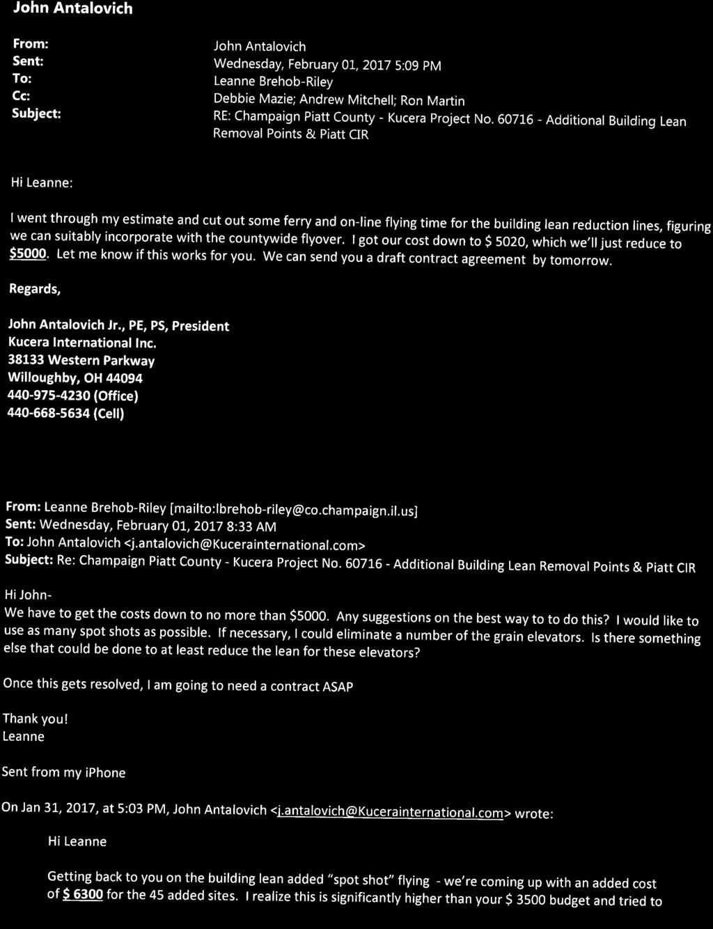
47


48
Metro Area Planning Agency. Request for Proposal Omaha-Lincoln Metro Area Imagery Project
 Metro Area Planning Agency Request for Proposal 2018 Omaha-Lincoln Metro Area Imagery Project 1. General Info 1.1. Objective The Metro Area Planning Agency ( MAPA ) in Omaha is soliciting proposals from
Baldwin and Mobile Counties, AL Orthoimagery Project Report. Submitted: March 23, 2016
 2015 Orthoimagery Project Report Submitted: Prepared by: Quantum Spatial, Inc 523 Wellington Way, Suite 375 Lexington, KY 40503 859-277-8700 Page i of iii Contents Project Report 1. Summary / Scope...
MINNESOTA DEPARTMENT OF TRANSPORTATION OFFICE OF LAND MANAGEMENT SURVEYING AND MAPPING SECTION PHOTOGRAMMETRY UNIT
 SEP. 2011 MINNESOTA DEPARTMENT OF TRANSPORTATION OFFICE OF LAND MANAGEMENT SURVEYING AND MAPPING SECTION PHOTOGRAMMETRY UNIT SPECIAL PROVISIONS FOR: GROUP 1: AERIAL PHOTOGRAPHY/PHOTOGRAMMETRIC LAB SERVICES
Acquisition of Aerial Photographs and/or Satellite Imagery
 Acquisition of Aerial Photographs and/or Satellite Imagery Acquisition of Aerial Photographs and/or Imagery From time to time there is considerable interest in the purchase of special-purpose photography
Orthoimagery Standards. Chatham County, Georgia. Jason Lee and Noel Perkins
 1 Orthoimagery Standards Chatham County, Georgia Jason Lee and Noel Perkins 2 Table of Contents Introduction... 1 Objective... 1.1 Data Description... 2 Spatial and Temporal Environments... 3 Spatial Extent
Acquisition of Aerial Photographs and/or Imagery
 Acquisition of Aerial Photographs and/or Imagery Acquisition of Aerial Photographs and/or Imagery From time to time there is considerable interest in the purchase of special-purpose photography contracted
MSB Imagery Program FAQ v1
 MSB Imagery Program FAQ v1 (F)requently (A)sked (Q)uestions 9/22/2016 This document is intended to answer commonly asked questions related to the MSB Recurring Aerial Imagery Program. Table of Contents
Leica ADS80 - Digital Airborne Imaging Solution NAIP, Salt Lake City 4 December 2008
 Luzern, Switzerland, acquired at 5 cm GSD, 2008. Leica ADS80 - Digital Airborne Imaging Solution NAIP, Salt Lake City 4 December 2008 Shawn Slade, Doug Flint and Ruedi Wagner Leica Geosystems AG, Airborne
 Proposal for Aerial Services Champaign and Piatt Counties, Illinois Issue Date: Monday, December 9, 2013 Proposals Due: 11:30 am, Wednesday, January 9, 2014 1.0 Introduction The Champaign County GIS Consortium
Basics of Photogrammetry Note#6
 Basics of Photogrammetry Note#6 Photogrammetry Art and science of making accurate measurements by means of aerial photography Analog: visual and manual analysis of aerial photographs in hard-copy format
DRAPP Product QAQC Participating Partner Process Guidelines Steve Ashbee ASPRS Certified Photogrammetrist PMI Project Management Professional Sanborn
 DRAPP Product QAQC Participating Partner Process Guidelines Steve Ashbee ASPRS Certified Photogrammetrist PMI Project Management Professional Sanborn Program Manager Area naming and other general feedback
REQUEST FOR PROPOSAL For Color Orthogonal & Color Oblique Imagery
 REQUEST FOR PROPOSAL For Color Orthogonal & Color Oblique Imagery OVERVIEW Austin County Appraisal District is seeking services from a qualified and experienced vendor for the delivery of color Orthogonal
CHAPTER 11 PRELIMINARY SITE PLAN APPROVAL PROCESS
 CHAPTER 11 PRELIMINARY SITE PLAN APPROVAL PROCESS 11.01.00 Preliminary Site Plan Approval 11.01.01 Intent and Purpose 11.01.02 Review 11.01.03 Application 11.01.04 Development Site to be Unified 11.01.05
Lesson 4: Photogrammetry
 This work by the National Information Security and Geospatial Technologies Consortium (NISGTC), and except where otherwise Development was funded by the Department of Labor (DOL) Trade Adjustment Assistance
Statewide Orthoimagery 2010 Data Delivery (excerpts for imagery review)
") Statewide Orthoimagery 2010 Data Delivery (excerpts for imagery review) Center for Geographic Information and Analysis Tim Johnson, Director March 2011 Project In Brief City of Durham PSAP Funded by NC
Statewide Orthoimagery 2010 Data Delivery (excerpts for imagery review) Center for Geographic Information and Analysis Tim Johnson, Director March 2011 Project In Brief City of Durham PSAP Funded by NC
Project Planning and Cost Estimating
 CHAPTER 17 Project Planning and Cost Estimating 17.1 INTRODUCTION Previous chapters have outlined and detailed technical aspects of photogrammetry. The basic tasks and equipment required to create various
Sample Copy. Not For Distribution.
 Photogrammetry, GIS & Remote Sensing Quick Reference Book i EDUCREATION PUBLISHING Shubham Vihar, Mangla, Bilaspur, Chhattisgarh - 495001 Website: www.educreation.in Copyright, 2017, S.S. Manugula, V.
HYDROGRAPHIC SURVEY STANDARDS AND DELIVERABLES
 TABLE OF CONTENTS 1. HYDROGRAPHIC SURVEY METHODOLOGY... 3 2. HYDROGRAPHIC SURVEY REFERENCE STANDARDS... 3 3. HYDROGRAPHIC SURVEY CRITERIA... 3 3.1 HYDROGRAPHIC SURVEYS OVER NON GAZETTED NAVIGABLE WATERS*:...
accuracy. You even hear the terms subcentimeter or even millimeter absolute accuracy during some of these
 Question: I would like to get your expert opinion on a dataset I just received. It is UAS-based imagery collected to produce a 50cm Digital Elevation Models (DEM) and 5cm resolution true color orthos.
Volume 1 - Module 6 Geometry of Aerial Photography. I. Classification of Photographs. Vertical
 RSCC Volume 1 Introduction to Photo Interpretation and Photogrammetry Table of Contents Module 1 Module 2 Module 3.1 Module 3.2 Module 4 Module 5 Module 6 Module 7 Module 8 Labs Volume 1 - Module 6 Geometry
PHOTOGRAMMETRY STEREOSCOPY FLIGHT PLANNING PHOTOGRAMMETRIC DEFINITIONS GROUND CONTROL INTRODUCTION
 PHOTOGRAMMETRY STEREOSCOPY FLIGHT PLANNING PHOTOGRAMMETRIC DEFINITIONS GROUND CONTROL INTRODUCTION Before aerial photography and photogrammetry became a reliable mapping tool, planimetric and topographic
9 LAND SURVEYING. 9.1 General. 9.2 Administrative Requirements Standards Meetings Survey Data Provided to the Design-Builder
 9 LAND SURVEYING 9.1 General The Design-Builder shall conduct all Work necessary to meet the requirements associated with land surveying, including Project and supplemental horizontal and vertical control
HIGH RESOLUTION COLOR IMAGERY FOR ORTHOMAPS AND REMOTE SENSING. Author: Peter Fricker Director Product Management Image Sensors
 HIGH RESOLUTION COLOR IMAGERY FOR ORTHOMAPS AND REMOTE SENSING Author: Peter Fricker Director Product Management Image Sensors Co-Author: Tauno Saks Product Manager Airborne Data Acquisition Leica Geosystems
REQUEST FOR PROPOSAL AERIAL PHOTOGRAPHY & DIGITAL MAPPING ROADS DEPARTMENT
 REQUEST FOR PROPOSAL AERIAL PHOTOGRAPHY & DIGITAL MAPPING ROADS DEPARTMENT The Cherokee Nation is requesting proposals from qualified professionals to provide aerial photography and digital mapping of
DRAPP 2014 DATA ACCEPTANCE TESTING (DAT) SCOPE OF WORK August 13, 2013
 SCOPE OF WORK August 13, 2013") DRAPP 2014 DATA ACCEPTANCE TESTING (DAT) SCOPE OF WORK August 13, 2013 Contents Background... 2 Summary... 2 Definitions... 2 Services to be Rendered... 3 Overview... 3 Geographic Extent... 3 Tasks and
DRAPP 2014 DATA ACCEPTANCE TESTING (DAT) SCOPE OF WORK August 13, 2013 Contents Background... 2 Summary... 2 Definitions... 2 Services to be Rendered... 3 Overview... 3 Geographic Extent... 3 Tasks and
Phase One 190MP Aerial System
 White Paper Phase One 190MP Aerial System Introduction Phase One Industrial s 100MP medium format aerial camera systems have earned a worldwide reputation for its high performance. They are commonly used
Aerial photography: Principles. Frame capture sensors: Analog film and digital cameras
 Aerial photography: Principles Frame capture sensors: Analog film and digital cameras Overview Introduction Frame vs scanning sensors Cameras (film and digital) Photogrammetry Orthophotos Air photos are
NJDEP GPS Data Collection Standards for GIS Data Development
 NJDEP GPS Data Collection Standards for GIS Data Development Bureau of Geographic Information Systems Office of Information Resource Management April 24 th, 2017 Table of Contents 1.0 Introduction... 3
GeoBase Raw Imagery Data Product Specifications. Edition
 GeoBase Raw Imagery 2005-2010 Data Product Specifications Edition 1.0 2009-10-01 Government of Canada Natural Resources Canada Centre for Topographic Information 2144 King Street West, suite 010 Sherbrooke,
TCC/SHORE TRANSIT BUS MAINTENANCE FACILITY - PHASE II
 SECTION 013300 - SUBMITTAL PROCEDURES PART 1 - GENERAL 1.1 RELATED DOCUMENTS A. Drawings and general provisions of the Contract, including General and Supplementary Conditions and other Division 01 Specification
AIRPORT MAPPING JUNE 2016 EXPLORING UAS EFFECTIVENESS GEOSPATIAL SLAM TECHNOLOGY FEMA S ROMANCE WITH LIDAR VOLUME 6 ISSUE 4
 VOLUME 6 ISSUE 4 JUNE 2016 AIRPORT MAPPING 18 EXPLORING UAS EFFECTIVENESS 29 GEOSPATIAL SLAM TECHNOLOGY 36 FEMA S ROMANCE WITH LIDAR Nearly 2,000 U.S. landfill facilities stand to gain from cost-effective
UNION COUNTY VOCATIONAL-TECHNICAL SCHOOLS West Hall Addition Project Raritan Road, Scotch Plains, NJ
 SECTION 013300 - SUBMITTAL PROCEDURES PART 1 - GENERAL 1.1 RELATED DOCUMENTS A. Drawings and general provisions of the Contract, including General and Supplementary Conditions and other Division 1 General
MONITORING RUBBLE-MOUND COASTAL STRUCTURES WITH PHOTOGRAMMETRY
 ,. CETN-III-21 2/84 MONITORING RUBBLE-MOUND COASTAL STRUCTURES WITH PHOTOGRAMMETRY INTRODUCTION: Monitoring coastal projects usually involves repeated surveys of coastal structures and/or beach profiles.
2019 NYSAPLS Conf> Fundamentals of Photogrammetry for Land Surveyors
 2019 NYSAPLS Conf> Fundamentals of Photogrammetry for Land Surveyors George Southard GSKS Associates LLC Introduction George Southard: Master s Degree in Photogrammetry and Cartography 40 years working
Request for Proposals: 2019 Flight for Ada and Canyon Counties, Idaho Flight for Ada and Canyon Counties, Idaho November 7, 2018 by 5 p.m.
 Request for Proposals: 2019 Flight for Ada and Canyon Counties, Idaho 1 RFP Summary RFP Number RFP 2019-13 RFP Title Deadline for Submittal Scope Send Submittals to Direct Inquires to COMPASS Project Manager
OLC Turnbull. wsidata.com
 OLC Turnbull wsidata.com August 26, 2013 Base station set up over control TURN_03 Data collected for: Department of Geology and Mineral Industries 800 NE Oregon Street Suite 965 Portland, OR 97232 Prepared
VisionMap A3 Edge A Single Camera for Multiple Solutions
 Photogrammetric Week '15 Dieter Fritsch (Ed.) Wichmann/VDE Verlag, Belin & Offenbach, 2015 Raizman, Gozes 57 VisionMap A3 Edge A Single Camera for Multiple Solutions Yuri Raizman, Adi Gozes, Tel-Aviv ABSTRACT
High Resolution Sensor Test Comparison with SPOT, KFA1000, KVR1000, IRS-1C and DPA in Lower Saxony
 High Resolution Sensor Test Comparison with SPOT, KFA1000, KVR1000, IRS-1C and DPA in Lower Saxony K. Jacobsen, G. Konecny, H. Wegmann Abstract The Institute for Photogrammetry and Engineering Surveys
Flood modelling and management. Glasgow University. 8 September Paul Shaw - GeoVision
 Flood modelling and management Glasgow University 8 September 2004 Paul Shaw - GeoVision How important are heights in flood modelling? Comparison of data collection technologies GPS - Global Positioning
MISSISSIPPI STATE UNIVERSITY Office of Planning Design and Construction Administration
 SECTION 01 340 - SHOP DRAWINGS, PRODUCT DATA AND SAMPLES PART 1 - GENERAL 1.1 RELATED DOCUMENTS A. Drawings and general provisions of the Contract, including General and Supplementary Conditions and other
EXAMPLES OF TOPOGRAPHIC MAPS PRODUCED FROM SPACE AND ACHIEVED ACCURACY CARAVAN Workshop on Mapping from Space, Phnom Penh, June 2000
 EXAMPLES OF TOPOGRAPHIC MAPS PRODUCED FROM SPACE AND ACHIEVED ACCURACY CARAVAN Workshop on Mapping from Space, Phnom Penh, June 2000 Jacobsen, Karsten University of Hannover Email: karsten@ipi.uni-hannover.de
JEFFERSON LAB TECHNICAL ENGINEERING & DEVELOPMENT FACILITY (TEDF ONE) Newport News, Virginia
 Newport News, Virginia") BULLETIN NO. 6 TO THE PLANS AND SPECIFICATIONS FOR JEFFERSON LAB TECHNICAL ENGINEERING & DEVELOPMENT FACILITY (TEDF ONE) Newport News, Virginia EwingCole Architects.Engineers.Interior Designers.Planners
BULLETIN NO. 6 TO THE PLANS AND SPECIFICATIONS FOR JEFFERSON LAB TECHNICAL ENGINEERING & DEVELOPMENT FACILITY (TEDF ONE) Newport News, Virginia EwingCole Architects.Engineers.Interior Designers.Planners
Planet Labs Inc 2017 Page 2
 SKYSAT IMAGERY PRODUCT SPECIFICATION: ORTHO SCENE LAST UPDATED JUNE 2017 SALES@PLANET.COM PLANET.COM Disclaimer This document is designed as a general guideline for customers interested in acquiring Planet
CALIBRATING THE NEW ULTRACAM OSPREY OBLIQUE AERIAL SENSOR Michael Gruber, Wolfgang Walcher
 CALIBRATING THE NEW ULTRACAM OSPREY OBLIQUE AERIAL SENSOR Michael Gruber, Wolfgang Walcher Microsoft UltraCam Business Unit Anzengrubergasse 8/4, 8010 Graz / Austria {michgrub, wwalcher}@microsoft.com
SECTION SUBMITTAL PROCEDURES
 SECTION 01330 - SUBMITTAL PROCEDURES PART 1 - GENERAL 1.1 RELATED DOCUMENTS A. Drawings and general provisions of the Contract, including General and Supplementary Conditions and other Division 1 Specification
Helicopter Aerial Laser Ranging
 Helicopter Aerial Laser Ranging Håkan Sterner TopEye AB P.O.Box 1017, SE-551 11 Jönköping, Sweden 1 Introduction Measuring distances with light has been used for terrestrial surveys since the fifties.
MAPPING DAMAGES CAUSED BY THE OCTOBER 2003 WILDFIRES IN CALIFORNIA
 MAPPING DAMAGES CAUSED BY THE OCTOBER 2003 WILDFIRES IN CALIFORNIA Louis Demargne & Mitch Jordan EarthData International 7320 Executive Way, Frederick, MD 21702 ABSTRACT EarthData, in coordination with
Photogrammetry. Lecture 4 September 7, 2005
 Photogrammetry Lecture 4 September 7, 2005 What is Photogrammetry Photogrammetry is the art and science of making accurate measurements by means of aerial photography: Analog photogrammetry (using films:
Abstract Quickbird Vs Aerial photos in identifying man-made objects
 Abstract Quickbird Vs Aerial s in identifying man-made objects Abdullah Mah abdullah.mah@aramco.com Remote Sensing Group, emap Division Integrated Solutions Services Department (ISSD) Saudi Aramco, Dhahran
SECTION SUBMITTAL PROCEDURES PART 1 - GENERAL 1.1 RELATED DOCUMENTS
 SECTION 01 33 00 - SUBMITTAL PROCEDURES PART 1 - GENERAL 1.1 RELATED DOCUMENTS A. Drawings and general provisions of the Contract, including General and Supplementary Conditions and other Division 01 Specification
SECTION SUBMITTAL PROCEDURES
 SECTION 013300 PART 1 - GENERAL 1.1 RELATED DOCUMENTS A. Drawings and general provisions of the Contract, including General and Supplementary Conditions and other Division 01 Specification Sections, apply
Land Records Management Division North Carolina Department of the Secretary of State. Spring 2007
 Technical Specifications for Base, Cadastral and Digital Mapping (Orthophotos) Land Records Management Division North Carolina Department of the Secretary of State Spring 2007 Page 1 of 84 PREFACE The
Configuration, Capabilities, Limitations, and Examples
 FUGRO EARTHDATA, Inc. Introduction to the New GeoSAR Interferometric Radar Sensor Bill Sharp GeoSAR Regional Director - Americas Becky Morton Regional Manager Configuration, Capabilities, Limitations,
Option 1. Design Options are diverse e.g. new route alignments covering a wide area. Option 2. Design Options are restricted
 MINIMUM STANDARD Z/16 SURVEY SPECIFICATIONS 1. GENERAL This specification sets out the Consultant s requirements for topographical survey (ground and aerial) for the Detailed Business Case (DBC) and Pre-Implementation
CHAPTER 5 PHOTOGRAMMETRIC SURVEYS
 CHAPTER 5 PHOTOGRAMMETRIC SURVEYS Chapter Contents Sec. 5.01 Sec. 5.02 Sec. 5.03 Sec. 5.04 Sec. 5.05 Sec. 5.06 Sec. 5.07 Sec. 5.08 Sec. 5.09 Sec. 5.10 Sec. 5.11 Sec. 5.12 Sec. 5.13 Sec. 5.14 Sec. 5.15
Recurring Aerial Imagery Acquisition Program
 Recurring Aerial Imagery Acquisition Program MSB Project No. 16-130 Report 4 of 5 Analysis of Aerial Imagery Acquisition Options Prepared By: Kinney Engineering, LLC 3909 Arctic Blvd, Ste 400 Anchorage,
An Introduction to Geomatics. Prepared by: Dr. Maher A. El-Hallaq خاص بطلبة مساق مقدمة في علم. Associate Professor of Surveying IUG
 An Introduction to Geomatics خاص بطلبة مساق مقدمة في علم الجيوماتكس Prepared by: Dr. Maher A. El-Hallaq Associate Professor of Surveying IUG 1 Airborne Imagery Dr. Maher A. El-Hallaq Associate Professor
Section Meetings Section Material and Equipment. None Required
 January 2000 Page 1 of 8 PART 1 GENERAL 1.01 OTHER CONTRACT DOCUMENTS 1.02 DESCRIPTION OF WORK 1.03 RELATED WORK PART 2 PRODUCTS The General Conditions of the Contract, General Requirements and Supplemental
How to. Go Smoothly. Make Your Next Project. Oblique color aerial photograph from a fl yover of the Island of Mayaguana in the Bahamas
 Color infrared aerial photograph (1:12,000) of a Cape Cod estuary for the U.S. Fish & Wildlife for use in aquatic vegetation studies Oblique color aerial photograph from a fl yover of the Island of Mayaguana
NORTHWESTERN UNIVERSITY PROJECT NAME JOB # ISSUED: 03/29/2017
 SECTION 01 3300 - SUBMITTAL PROCEDURES PART 1 - GENERAL 1.1 RELATED DOCUMENTS A. Drawings and general provisions of the Contract, including General and Supplementary Conditions and other Division 01 Specification
East Central College
 SECTION 013300 - SUBMITTAL PROCEDURES PART 1 - GENERAL 1.1 RELATED DOCUMENTS A. Drawings and general provisions of the Contract, including General and Supplementary Conditions and other Division 01 Specification
A. Action Submittals: Written and graphic information that requires Engineer's responsive action.
 SECTION 01330 - SUBMITTAL PROCEDURES PART 1 - GENERAL 1.1 RELATED DOCUMENTS A. Drawings and general provisions of the Contract, including General and Supplementary Conditions and other Division 1 Specification
SECTION CONSTRUCTION PHOTOGRAPHS AND VIDEO RECORDING
 SECTION 01321 CONSTRUCTION PHOTOGRAPHS AND VIDEO RECORDING PART 1 GENERAL 1.01 SUMMARY A. Employ a competent photographer to take construction record photographs for preconstruction conditions, periodically
Geometry of Aerial Photographs
 Geometry of Aerial Photographs Aerial Cameras Aerial cameras must be (details in lectures): Geometrically stable Have fast and efficient shutters Have high geometric and optical quality lenses They can
NEVADA DEPARTMENT OF TRANSPORTATION Addendum 3 to RFP July 28, 2017
 NEVADA DEPARTMENT OF TRANSPORTATION Addendum 3 to RFP 697-16-016 July 28, 2017 Reference is made to the Request for Proposal (RFP) to Service Providers for Nevada Shared Radio Replacement Project, upon
UltraCam and UltraMap Towards All in One Solution by Photogrammetry
 Photogrammetric Week '11 Dieter Fritsch (Ed.) Wichmann/VDE Verlag, Belin & Offenbach, 2011 Wiechert, Gruber 33 UltraCam and UltraMap Towards All in One Solution by Photogrammetry ALEXANDER WIECHERT, MICHAEL
LPIS Orthoimagery An assessment of the Bing imagery for LPIS purpose
 LPIS Orthoimagery An assessment of the Bing imagery for LPIS purpose Slavko Lemajić Wim Devos, Pavel Milenov GeoCAP Action - MARS Unit - JRC Ispra Tallinn, 24 th November 2011 Outline JRC`s Ortho specifications
UCCS University Hall Fire Sprinkler System Upgrade March 1, 2011 RTA SECTION SUBMITTAL PROCEDURES PART 1 - GENERAL
 SECTION 013300 - SUBMITTAL PROCEDURES PART 1 - GENERAL 1.1 RELATED DOCUMENTS A. Drawings and general provisions of the Contract, including General and Supplementary Conditions and other Division 01 Specification
.2 Accompany all submissions with a transmittal letter, in duplicate, containing:.4 Specification Section number for each submittal
 City of Winnipeg Brady Road Landfill Site Section 01300 New Entrance and Scale Facility Page 1 of 4 SUBMITTALS 1. SHOP DRAWINGS 1.1 General.1 Arrange for the preparation of clearly identified Shop Drawings
DIVISION 1 - GENERAL REQUIREMENTS SECTION SUBMITTALS
 DIVISION 1 - GENERAL REQUIREMENTS SECTION 01300 - SUBMITTALS PART 1 - GENERAL 1.1 STIPULATIONS A. The section "Special Requirements" forms a part of this section by this reference thereto and shall have
SECTION SUBMITTALS. A. PART A and DIVISION 1 of PART B are hereby made a part of this SECTION.
 SECTION 013300 PART 1 GENERAL 1.01 GENERAL REQUIREMENTS A. PART A and DIVISION 1 of PART B are hereby made a part of this SECTION. B. Examine all conditions as they exist at the project prior to submitting
Camera Calibration Certificate No: DMC II
 Calibration DMC II 140-036 Camera Calibration Certificate No: DMC II 140-036 For Midwest Aerial Photography 7535 West Broad St, Galloway, OH 43119 USA Calib_DMCII140-036.docx Document Version 3.0 page
Camera Calibration Certificate No: DMC II
 Calibration DMC II 230 015 Camera Calibration Certificate No: DMC II 230 015 For Air Photographics, Inc. 2115 Kelly Island Road MARTINSBURG WV 25405 USA Calib_DMCII230-015_2014.docx Document Version 3.0
Camera Calibration Certificate No: DMC II
 Calibration DMC II 140-005 Camera Calibration Certificate No: DMC II 140-005 For Midwest Aerial Photography 7535 West Broad St, Galloway, OH 43119 USA Calib_DMCII140-005.docx Document Version 3.0 page
Processing of stereo scanner: from stereo plotter to pixel factory
 Photogrammetric Week '03 Dieter Fritsch (Ed.) Wichmann Verlag, Heidelberg, 2003 Bignone 141 Processing of stereo scanner: from stereo plotter to pixel factory FRANK BIGNONE, ISTAR, France ABSTRACT With
GEO 428: DEMs from GPS, Imagery, & Lidar Tuesday, September 11
 GEO 428: DEMs from GPS, Imagery, & Lidar Tuesday, September 11 Global Positioning Systems GPS is a technology that provides Location coordinates Elevation For any location with a decent view of the sky
PLANET IMAGERY PRODUCT SPECIFICATIONS PLANET.COM
 PLANET IMAGERY PRODUCT SPECIFICATIONS SUPPORT@PLANET.COM PLANET.COM LAST UPDATED JANUARY 2018 TABLE OF CONTENTS LIST OF FIGURES 3 LIST OF TABLES 4 GLOSSARY 5 1. OVERVIEW OF DOCUMENT 7 1.1 Company Overview
CanImage. (Landsat 7 Orthoimages at the 1: Scale) Standards and Specifications Edition 1.0
 Standards and Specifications Edition 1.0") CanImage (Landsat 7 Orthoimages at the 1:50 000 Scale) Standards and Specifications Edition 1.0 Centre for Topographic Information Customer Support Group 2144 King Street West, Suite 010 Sherbrooke, QC
CanImage (Landsat 7 Orthoimages at the 1:50 000 Scale) Standards and Specifications Edition 1.0 Centre for Topographic Information Customer Support Group 2144 King Street West, Suite 010 Sherbrooke, QC
Answer: Qualification statement should be provided with the bid.
 Little Diversified Architectural Consulting, Inc. 5815 Westpark Drive Charlotte, North Carolina 28217 Phone: 704-525-6350 Fax: 704-561-8700 Lincoln County Probation Renovation 208 N. Government Street
Remote Sensing Platforms
 Types of Platforms Lighter-than-air Remote Sensing Platforms Free floating balloons Restricted by atmospheric conditions Used to acquire meteorological/atmospheric data Blimps/dirigibles Major role - news
Aerial Triangulation Radiometry Essentials Dense Matching Ortho Generation
 Radiometry Aerial Triangulation Essentials Dense Matching Ortho Generation Highly advanced photogrammetric workflow system for UltraCam images. Microsoft UltraMap is a state-of-the-art, end-to-end, complete
A. This section specifies procedural requirements for Shop Drawings, product data, samples, and other miscellaneous Work-related submittals.
 SECTION 01300 PART 1 GENERAL 1.1 SECTION INCLUDES A. Description of Requirements B. Submittal Procedures C. Specific Submittal Requirements D. Action on Submittals E. Repetitive Review 1.2 DESCRIPTION
OLC West Metro. wsidata.com
 OLC West Metro wsidata.com February 19, 2013 Hillsboro Airport, LiDAR point cloud Data collected for: Department of Geology and Mineral Industries 800 NE Oregon Street Suite 965 Portland, OR 97232 Prepared
Validation of the QuestUAV PPK System
 Validation of the QuestUAV PPK System 3cm in xy, 400ft, no GCPs, 100Ha, 25 flights Nigel King 1, Kerstin Traut 2, Cameron Weeks 3 & Ruairi Hardman 4 1 Director QuestUAV, 2 Data Analyst QuestUAV, 3 Production
Fiscal 2007 Environmental Technology Verification Pilot Program Implementation Guidelines
 Fifth Edition Fiscal 2007 Environmental Technology Verification Pilot Program Implementation Guidelines April 2007 Ministry of the Environment, Japan First Edition: June 2003 Second Edition: May 2004 Third
Camera Calibration Certificate No: DMC III 27542
 Calibration DMC III Camera Calibration Certificate No: DMC III 27542 For Peregrine Aerial Surveys, Inc. #201 1255 Townline Road Abbotsford, B.C. V2T 6E1 Canada Calib_DMCIII_27542.docx Document Version
APPLICATIONS AND LESSONS LEARNED WITH AIRBORNE MULTISPECTRAL IMAGING
 APPLICATIONS AND LESSONS LEARNED WITH AIRBORNE MULTISPECTRAL IMAGING James M. Ellis and Hugh S. Dodd The MapFactory and HJW Walnut Creek and Oakland, California, U.S.A. ABSTRACT Airborne digital frame
Camera Calibration Certificate No: DMC II
 Calibration DMC II 230 027 Camera Calibration Certificate No: DMC II 230 027 For Peregrine Aerial Surveys, Inc. 103-20200 56 th Ave Langley, BC V3A 8S1 Canada Calib_DMCII230-027.docx Document Version 3.0
Part 9: Application Procedures and Rules for Terrestrial S-DARS Undertakings (Satellite Digital Audio Radio Service)
") Issue 2 January 2009 Spectrum Management and Telecommunications Broadcasting Procedures and Rules Part 9: Application Procedures and Rules for Terrestrial S-DARS Undertakings (Satellite Digital Audio Radio
Issue 2 January 2009 Spectrum Management and Telecommunications Broadcasting Procedures and Rules Part 9: Application Procedures and Rules for Terrestrial S-DARS Undertakings (Satellite Digital Audio Radio
Application of GIS to Fast Track Planning and Monitoring of Development Agenda
 Application of GIS to Fast Track Planning and Monitoring of Development Agenda Radiometric, Atmospheric & Geometric Preprocessing of Optical Remote Sensing 13 17 June 2018 Outline 1. Why pre-process remotely
The coordinate system and vertical datum shall be noted in the drawing in the metadata.
 Purpose This document is provided for informational purposes and to assure data compatibility and compliance for as-built drawings or vector data formats specifically for the 354th Civil Engineer Squadron
Technology transactions and outsourcing deals: a practitioner s perspective. Michel Jaccard
 Technology transactions and outsourcing deals: a practitioner s perspective Michel Jaccard Overview Introduction : IT transactions specifics and outsourcing deals Typical content of an IT outsourcing agreement
SPOT 5 / HRS: a key source for navigation database
 SPOT 5 / HRS: a key source for navigation database CONTENT DEM and satellites SPOT 5 and HRS : the May 3 rd 2002 revolution Reference3D : a tool for navigation and simulation Marc BERNARD Page 1 Report
SECTION ADMINISTRATIVE REQUIREMENTS SECTION ADMINISTRATIVE REQUIREMENTS
 PART 1 GENERAL 1.01 SECTION INCLUDES A. Project Coordination. B. Preconstruction meeting. C. Progress meetings. D. Preinstallation conferences. E. Requests for information (RFI). F. Coordination drawings.
Camera Calibration Certificate No: DMC IIe
 Calibration DMC IIe 230 23522 Camera Calibration Certificate No: DMC IIe 230 23522 For Richard Crouse & Associates 467 Aviation Way Frederick, MD 21701 USA Calib_DMCIIe230-23522.docx Document Version 3.0
SUBMITTAL PROCEDURES
 SUBMITTAL PROCEDURES PART 1 GENERAL The ASPA Project Engineer (APE) may request submittals in addition to those specified when deemed necessary to adequately describe the work covered in the respective
1. Land survey Work. 2. Civil and Structural engineering services.
 SECTION 01050 FIELD ENGINEERING PART 1 - GENERAL 1.01 RELATED DOCUMENTS A. Drawings and general provisions of the Contract, including General and Supplementary Conditions and other Division-1 Specification
SANITARY SEWER SYSTEM ADMINISTRATIVE STANDARDS A.1 SANITARY SEWER SYSTEM PLAN SUBMITTAL PROCEDURES AND GENERAL REQUIREMENTS
 SANITARY SEWER SYSTEM ADMINISTRATIVE STANDARDS A.1 SANITARY SEWER SYSTEM PLAN SUBMITTAL PROCEDURES AND GENERAL REQUIREMENTS All plans for sanitary sewer main extensions, improvements and modifications
11/25/2009 CHAPTER THREE INTRODUCTION INTRODUCTION (CONT D) THE AERIAL CAMERA: LENS PHOTOGRAPHIC SENSORS
 THE AERIAL CAMERA: LENS PHOTOGRAPHIC SENSORS") INTRODUCTION CHAPTER THREE IC SENSORS Photography means to write with light Today s meaning is often expanded to include radiation just outside the visible spectrum, i. e. ultraviolet and near infrared
INTRODUCTION CHAPTER THREE IC SENSORS Photography means to write with light Today s meaning is often expanded to include radiation just outside the visible spectrum, i. e. ultraviolet and near infrared
UAS Photogrammetry Best Practices
 UAS Photogrammetry Best Practices Pennsylvania Society of Land Surveyors January 15, 2019 Bryan Baker Certified Mapping Scientist (UAS) Bryan Baker UAS Sales Manager Leica Geosystems Reality Capture Team