Image Optimization: The Sonographer s Responsibility. Prepared by Cathy Daniels, EdD, RTR, RDMS, RDCS, RVT
|
|
|
- Nelson Lucas
- 6 years ago
- Views:
Transcription
1 Image Optimization: The Sonographer s Responsibility Prepared by Cathy Daniels, EdD, RTR, RDMS, RDCS, RVT

2 Image Optimization: The Sonographer s Responsibility Cathy Daniels, EdD, RTR, RDMS, RDCS, RVT Disclosure Information: I have no financial relationships to disclose. I will not discuss off label use and/or investigational use in my presentation. I am the Director of Sonography Programs at Johnston Community College.
3 Objectives Learn what image optimization encompasses and why it is important Discern how the image needs to be improved and which tools will provide the needed enhancements Learn tips for optimal image optimization

4 What is Image Optimization? The use of various knobs or toggles to improve the visual quality of a diagnostic ultrasound image Source:

5 Why Optimize the Image? Facilitates correct interpretation Interactive questions on certification boards Expected that you optimize ALL images as a professional sonographer Source:

6 SDMS Scope of Practice Recognizes sonographic characteristics of normal and abnormal tissues, structures, and blood flow; adapts protocol as appropriate to further assess findings; adjusts scanning technique to optimize image quality and diagnostic information. Source:


7 It s YOUR responsibility as a sonographer to optimize the sonographic image. AVOID the easy button as it does not always make the image best. A machine cannot assess the image like a professional sonographer can.
8 Image Annotation ACR Guidelines (Section IV. Documentation) indicates that The initials of the operator should be accessible on the images or electronically on PACS. Images should be labeled with patient identification, facility identification, examination date, and image orientation.


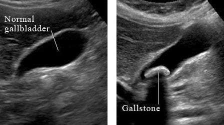
9 Upper Left corner of image Not over any anatomy or doppler waveform Never diagnose on an image Indicate the following: organ/area of interest scan plane (TRV or SAG) left or right special notations 3/ufiles/gallbladder%20web/normal-gb.jpg mages/gb2%20iow.jpeg 6V08/TQ7HB3VwGpI/AAAAAAAACJs/DsusWL8N2d U/s1600/fine-calculi-GB-blog-1a.jpg
10

11 Suggested Organ TRANS or SAG Patient position Special notes


12 Center the Area of Interest


13 Same for the Ultrasound Image


14 Patient Positioning Abdominal studies should rarely be completed with patient only SUPINE. Be creative with transducer manipulations and windows. Remove the pillow for carotids and improve distal imaging of ICA. Scan from the posterior window for a better ICA.

15 Know the Protocol Critical Thinking Skills Critique your images as you go (have an analytical process) Evaluate your image BEFORE you save it Go off axis when needed Video clip it if a still image cannot tell the story If you question what you see, so will the interpreting physician. Go ahead and answer the question. Always be humble enough to get someone else to look at it.
")

16 So How Do I Optimize the Image? (without using the easy button ) png/images/website-conversionrate-optimization.png


17 Many Tools Available Exam/Presets Transducer selection Frequency High/Low/MultiHz Harmonics Depth Focus Gain Controls Overall, TGC, LGC Sector Size Magnify/Zoom Compression/Dynamic Range B-color/Image Colorization Post-processing Sweep/Video Clip


18 Control Knobs Toggles Left Lessens or decreases Increases Usually Increases Usually Decreases
19 TGC Slide Pods Left Lessens darker Right Bright brighter


20 Exam Presets Pre-established parameters specific to study Use as a baseline for specific study and adjust accordingly Always reset preset before beginning each study m/d/l225/m/mxtg8qgpxsqp R2f503rGJBw.jpg
 Axial")

 Try")

21 Selecting the Transducer Resolution (use high frequency) Axial Resolution (determined by SPL) smaller SPL with High Frequencies better front to back resolution Depth (use low frequency) Try utilizing the multi-hertz feature too. Consider the size of near field vs. far field with the anatomy seen


22 Wider Display Format Narrow Display Format
23 Gen-L (low freq) Gen-M (higher freq)
24 PEN-H
25 Depth Shallow versus deep 2 finger widths from bottom of anatomy to bottom of image Do not clip anatomy in image Utilize depth throughout study Note: If you change depth, adjust FOCUS too.
26 Clipped Image Wasted Far Field
27 Abdominal Aorta (SAG) Example of why depth (and focus) should change throughout the exam

28 Perpendicular to Walls 90 to wall produces best reflection
 to optimize beam width Use multi-focus but at the sake of temporal")
29 Lateral Resolution Determined by Beam Width Use focus (narrowest part of sound beam) to optimize beam width Use multi-focus but at the sake of temporal resolution
30 Focus Position at the level of or just beyond the area of interest (narrower Beam Width resulting in better Lateral Resolution ) Enhances image in a specific region Utilize throughout exam as depth changes Multi-focus is best used with nonmoving structure (multi-focus decreases Temporal Resolution by slowing down the Frame Rate)

31 Single Focus vs Multi-focus Single Focus Multiple Focal Points

32 Gains 2D Overall Gain Doppler Gain Color Gain
33 Overall Gain The whole image needs correction Under gain (too little gain) Over gain (too much gain) % correction needed to optimize Too little Too much

34 Doppler Gain Enhances the doppler spectral display Useful with minimal or faint velocities Nice background and clean spectral window Too much
35 Color Gain Enhances the amount of color displayed to improve color fill-in in a vessel correct Too LOW Too HIGH

36 Color Wall Filter correct Too HIGH
37 Frequency & Color Flow Low Freq High Freq Doppler works best with lower frequencies

38 TGC/LGC cm markers Compensates for signal attenuation at different depths so all signals have similar intensity regardless of distance traveled Use according to image needs Near field Middle of image Far field LGC compensates on sides
39 Normal TGC banding
40 Adjusting TGC can make a vessel pop

41 Dual Image: Measurements Provides side to side comparison w/o measurements WITH measurements

42 Dual Image: 2D & Color Flow Provides side to side comparison w/o color WITH color


43 Temporal Resolution To image a moving structure as it the movement occurs Determined by frame rate
44 Imaging depth Frame Rate is determined by: Number of pulses per frame Number of focal points Sector size Line density The more work we ask the transducer to do, the more time it takes to do it; thereby slowing the frame rate.
45 Increase focal points = Frame Rate Single Focus Multiple Focal Points


46 Sector Size Increase sector size = frame rate due to more scan lines Less scan lines require less time and improves temporal resolution

47 Sector Size In addition, narrowing the sector size will get rid of unnecessary information and improve overall resolution image Smaller sector size

48 Line Density Increase line density = frame rate but.. The image is BETTER because of more scan lines!
49 Better resolution but slowest FR LD1 LD2 LD3 LD4
50 Imaging Depth Shallow depth = better temporal resolution Deeper depth requires more time for echo to return to Td. More time = less temporal resolution Greater the depth, less resolution. So scan deep enough to see organ. Don t waste the far field.
51 Shallow Depth Increased Depth
52 What creates the BEST temporal resolution? single focal point narrow sector size low line density

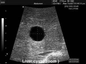
53 Zoom Enlarges the area of interest w/o loss of quality zoom
54 Dynamic Range or Compression DR = range of grays between smallest and largest signals Compression = varying shades of gray due to compressed signals Choose between hi/low contrast or gray scale
55 Range between Smallest - Largest Signals Normal Dynamic Range Less Dynamic Range More shades of gray Less shades of gray

56 Benefits of Color
57 B-color/ Image Colorization/Colorize the substitution of the basic grayscale image with a hue other than gray in order to improve visual perception of images. Not useful when using color flow Can also be helpful with doppler spectrum
58 2D image Image Colorization
59 Different Color Hues
60 May help you see PSV or EDV better Colorize PW
61 Persistence Decrease = grainy image Increase = smoothes image Persistence 0 Persistence 9 CAUTION: Increasing PERSISTENCE = frame rate due to averaging of frames


62 Edge Sharpens Lower: smoother, less noise Higher: sharper edges
63 Edge 1 Edge 7 smoother sharper

64 Still Image or Video Clip Helpful for presenting information that is best seen in real time versus still image
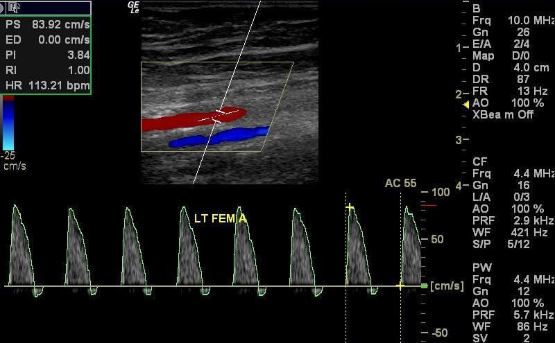
65 Doppler Optimization Scale Baseline Wall Filter

66 Scale (PRF) Optimize scale so that the waveform is not too small (decrease scale) If PRF is too low, then aliasing occurs. Hi PRF.decrease depth aliasing Doppler scale vs. color scale Don t make me squint. scale too high
67 Baseline Zero level on doppler spectrum or color bar Emphasize the side of the baseline for + or flow direction Can be adjusted to help with aliasing correct Baseline too HIGH for flow above the line
68 correct Move the baseline down to emphasize flow above the line

69 Color Baseline
70 Wall Filter Used to eliminate noise or clutter along the BL Decrease the wall filter to allow more echoes Increasing the filter takes away information along baseline and may overestimate mean velocities

71 To Correct PW Aliasing Increase scale May adjust BL Increase the scale
72 To Correct Color Aliasing Look at the center of the vessel or center of stenotic flow to see aliasing due to velocities faster than the color scale allows Flow is naturally faster in the center of the vessel Increase color scale May adjust baseline
73 Sample Volume Size & Location Gate Size/Location Increase gate size = increases signal-to-noise ratio L/C/R (use smallest angle) Angle Correct should be parallel to flow If fixed 60º, then toe-heel or move Td so vessel fits.
74 Sample Location Center of Flow Next to vessel wall Good window w/o spectral broadening Too close to vessel wall; poor angle

75 Sample Volume Size Correct Too Large Clean window + spectral broadening
")
76 Listen for the BEST Doppler signal SV in center of vessel SV not on wall Small SV Toe-Heel or Heel-Toe (produces smallest doppler angle of incident) LISTEN
")


77 L/C/R Must know direction of flow (toward or away from ) Flow toward transducer is most accurate Flow away from transducer is underestimated 90 degrees = no flow or color
78 L/C/R Steered with perpendicular incidence Good; steered toward flow
79 Carotid Imaging Center Steer 90 Toward Flow Steer Away from flow (underestimates velocity)
80 Parallel to Flow/Angle Correct 0 doppler angle is most correct if parallel to flow for consistency between studies Use angle correct correctly good poor waveform 76º

81 Remember Perpendicular to Walls 90 to wall produces best reflection

82 Perpendicular to Flow is BAD PW CF Horizontal vessel Color box is perpendicular to flow


83 Parallel to Flow 0 to flow yields most accurate velocity

84 Heel Toe to Improve PW Better: ICA is off the baseline more.
85 Heel Toe to Improve CF
86 Scenarios for identifying the best correction needed

87 Increase overall gain by 25% Decrease overall gain by 50% Decrease TGC in the far field by 50% Select a higher frequency Td

88 What s Wrong? Need to Use Correct Annotation Methods Do not diagnose on the image.

89 Increase overall gain by 25% Decrease overall gain by 25% Increase TGC in the near field by 50% Select a higher frequency Td

90 Increase PW scale by 25% Decrease PW scale by 25% Increase CF scale by 25% Decrease filter by 25%

91 What s Wrong? Do not diagnose on the image.

92 Increase scale by 50% Move baseline up Decrease scale by 25% Increase color gain by 30%
93 Remember Every image you submit is a direct reflection of your professionalism and scanning abilities. The interpreting physician depends on you. Your patient depends on you. Your images and protocol define your credibility as a highly-skilled sonographer. Let each image be your.

94 Image Optimization: YOUR Responsibility Thank you for allowing me to share with you today!
4 Working With Scan Modes
 4 Working With Scan Modes Scan Modes Overview All of the information in this chapter pertains to live imaging. Many of the controls and functions change when you freeze the scan. For information on using
Answer: TGC is needed to amplify echoes from deeper structures so that they appear as bright as similar structures located at more shallow depths.
 Q47. When performing a sonogram why the sonographer needs to use the TGC? TGC is needed to amplify echoes from deeper structures so that they appear as bright as similar structures located at more shallow
SONOGRAPHIC PHYSICS, INSTRUMENTATION & DOPPLER REVIEW Part 3
 SONOGRAPHIC PHYSICS, INSTRUMENTATION & DOPPLER REVIEW 2012 Part 3 1 Doppler Imaging 2 DOPPLER TRANSDUCER SAME FREQUENCY During Doppler operation, the reflected sound has the same frequency as the transmitted
Artifacts. Artifacts. Causes. Imaging assumptions. Common terms used to describe US images. Common terms used to describe US images
 Artifacts Artifacts Chapter 20 What are they? Simply put they are an error in imaging These artifacts include reflections that are: not real incorrect shape, size or position incorrect brightness displayed
Optimisation of Image Acquisition Bordeaux 16th November J.S. McGhie W.B. Vletter R. Frowijn No disclosures
 Optimisation of Image Acquisition Bordeaux 16th November 2016 J.S. McGhie W.B. Vletter R. Frowijn No disclosures Image optimisation: The Echo machine It looks difficult to drive an echo machine!! Some
Lesson 12: Doppler Principles. This lesson contains 50 slides plus 26 multiple-choice questions.
 Lesson 12: Doppler Principles This lesson contains 50 slides plus 26 multiple-choice questions. Accompanying text for the slides in this lesson can be found on pages 59 through 80 in the textbook: DOPPLER
Lesson 06: Pulse-echo Imaging and Display Modes. These lessons contain 26 slides plus 15 multiple-choice questions.
 Lesson 06: Pulse-echo Imaging and Display Modes These lessons contain 26 slides plus 15 multiple-choice questions. These lesson were derived from pages 26 through 32 in the textbook: ULTRASOUND IMAGING
The Physics of Echo. The Physics of Echo. The Physics of Echo Is there pericardial calcification? 9/30/13
 Basic Ultrasound Physics Kirk Spencer MD Speaker has no disclosures to make Sound Audible range 20Khz Medical ultrasound Megahertz range Advantages of imaging with ultrasound Directed as a beam Tomographic
Lesson 06: Pulse-echo Imaging and Display Modes. This lesson contains 22 slides plus 15 multiple-choice questions.
 Lesson 06: Pulse-echo Imaging and Display Modes This lesson contains 22 slides plus 15 multiple-choice questions. Accompanying text for the slides in this lesson can be found on pages 26 through 32 in
Ultrasound & Artifacts
 ISSN 2005-7881 Journal of Neurosonology 3(Suppl. 2):1-17, 2011 Ultrasound & Artifacts Siryung Han The Catholic University of Korea Artifacts False image- echoes without anatomic correlate US image dose
Physics of Ultrasound Ultrasound Imaging and Artifacts รศ.นพ.เดโช จ กราพาน ชก ล สาขาหท ยว ทยา, ภาคว ชาอาย รศาสตร คณะแพทยศาสตร ศ ร ราชพยาบาล
 Physics of Ultrasound Ultrasound Imaging and Artifacts รศ.นพ.เดโช จ กราพาน ชก ล สาขาหท ยว ทยา, ภาคว ชาอาย รศาสตร คณะแพทยศาสตร ศ ร ราชพยาบาล Diagnosis TTE TEE ICE 3D 4D Evaluation of Cardiac Anatomy Hemodynamic
The physics of ultrasound. Dr Graeme Taylor Guy s & St Thomas NHS Trust
 The physics of ultrasound Dr Graeme Taylor Guy s & St Thomas NHS Trust Physics & Instrumentation Modern ultrasound equipment is continually evolving This talk will cover the basics What will be covered?
Quick Reference Guide
 siemens.com/nx3 Quick Reference Guide ACUSON NX3 Series Contents 2 System Overview 3 Getting Started 8 2D Mode and M-mode 12 Color and Spectral Doppler 24 Measurements and Calculations 38 Text, Arrows
Diagnostic Ultrasound System. Operation Note
 M5 Diagnostic Ultrasound System Table of Contents System Introduction...3 Control Panel...4 Control Panel...5 Control Panel...6 Control Panel...7 Control Panel...8 Control Panel...9 Power ON / OFF the
DC-6. Diagnostic Ultrasound System
 DC-6 Diagnostic Ultrasound System DC-6 is a general purpose color Doppler ultrasound system aiming at most clinical areas both in exam and research with various transducers and multi software packages
Introduction to Ultrasound Physics
 Introduction to Ultrasound Physics Vassilis Sboros Medical Physics and Cardiovascular Sciences University of Edinburgh Transverse waves Water remains in position Disturbance traverse producing more wave
Pass Ultrasound Physics Exam
 Pass Ultrasound Physics Exam Match the Answers By Mansoor Khan MBBS, RDMS, RDCS 1 Copyright 2014 Blue Cube Venture, LLC All rights reserved. The Pass Ultrasound Physics Exam Match the Answers is protected
Chapter 4. Pulse Echo Imaging. where: d = distance v = velocity t = time
 Chapter 4 Pulse Echo Imaging Ultrasound imaging systems are based on the principle of pulse echo imaging. These systems require the use of short pulses of ultrasound to create two-dimensional, sectional
Principles of Ultrasound Imaging Image Optimization
 Principles of Ultrasound Imaging Image Optimization Robert A. Levine, MD, FACE, ECNU Thyroid Center of New Hampshire Geisel School of Medicine at Dartmouth College Disclosures: No relevant financial or
Doppler Ultrasound. Amanda Watson.
 Doppler Ultrasound Amanda Watson amanda.watson1@nhs.net Before we start Why does blood appear black on a B-mode image? B-mode echoes vs. Doppler echoes In B-Mode we are concerned with the position and
Ultrasound Imaging Ultr Michael Dadd 2007
 Ultrasound Imaging Ultrasound Physics & Instrumentation - Recommended Reading 1. Diagnostic Ultrasound: Principles and Instruments (7th Ed) Frederick W Kremkau W B Saunders Company 2. Applied Physics &
Architecture of Quality Imaging Mary K. Henne, MS, CNMT, RDMS, RVT Ultrasound Education Specialist GE Healthcare
 Architecture of Quality Imaging Mary K. Henne, MS, CNMT, RDMS, RVT Ultrasound Education Specialist GE Healthcare 2 DOC1292532 Architecture of Quality Imaging Agile Acoustic Architecture E-Series and XDclear
S S S2 Operation Manual
 PREPARATION 1. How to create and input patient data? In the MAIN INTERFACE, press the key, to enter into the patient exam list interface. Then, click New patient item to create new patient files. Patient
Doppler in Obstetrics: book by K Nicolaides, G Rizzo, K Hecher. Chapter on Doppler ultrasound: principles and practice by Colin Deane
 Doppler in Obstetrics: book by K Nicolaides, G Rizzo, K Hecher Chapter on Doppler ultrasound: principles and practice by Colin Deane INTRODUCTION Competent use of Doppler ultrasound techniques requires
12/26/2017. Alberto Ardon M.D.
 Alberto Ardon M.D. 1 Preparatory Work Ultrasound Physics http://www.nysora.com/mobile/regionalanesthesia/foundations-of-us-guided-nerve-blockstechniques/index.1.html Basic Ultrasound Handling https://www.youtube.com/watch?v=q2otukhrruc
Design Your Performance
 MEDISON has been a leading name in diagnostic ultrasound since its foundation in 1985. As one of the only companies dedicated solely to ultrasound imaging, we have remained at the forefront of research
Key Physics and Doppler Principles
 Key Physics and Doppler Principles Robert A. Levine, MD, FACE, ECNU Thyroid Center of New Hampshire Geisel School of Medicine at Dartmouth College AACE/ACE Advanced Neck Ultrasound Training Course Disclosures:
DC-6 Expert. Diagnostic Ultrasound System
 DC-6 Expert Diagnostic Ultrasound System MINDRAY has newly released DC-6 Expert, a general purpose color Doppler ultrasound system with full ergonomic designs, supplying more accessible exams, higher imaging
M7Vet Diagnostic Ultrasound System. Operation Note
 M7Vet Diagnostic Ultrasound System Operation Note Table of Contents Table of Contents... i 1 System Introduction... 1 2 Control Panel... 2 3 Icons on the Screens... 6 4 Power ON/ OFF... 7 5 Enter or Search
Ultrasound Physics. History: Ultrasound 2/13/2019. Ultrasound
 Ultrasound Physics History: Ultrasound Ultrasound 1942: Dr. Karl Theodore Dussik transmission ultrasound investigation of the brain 1949-51: Holmes and Howry subject submerged in water tank to achieve
PERFORM Operating Document. Use and Maintenance of G.E. Ultrasound LOGIQ E
 PERFORM Operating Document Use and Maintenance of G.E. Ultrasound LOGIQ E PC-POD-IM-001-v02 Revision History Version Reason for Revision Date 01 New POD 22/May/2013 02 Minor changes only 2.2 Change responsibility
ACUSON X150 Knobology & User Guide
 ACUSON X150 Knobology & User Guide ACUSON X150 CONTROL PANEL Table of Contents The ACUSON X150 knobology and user guide is the clinicians quick reference of system terms, functions and capabilities. This
M5 Diagnostic Ultrasound System
 V0807 M5 Diagnostic Ultrasound System Mindray s ultrasound family is now introducing a new member, M5 hand-carried color Doppler system. M5, coming in a laptop size with comprehensive ergonomic design,
Ultrasound Beamforming and Image Formation. Jeremy J. Dahl
 Ultrasound Beamforming and Image Formation Jeremy J. Dahl Overview Ultrasound Concepts Beamforming Image Formation Absorption and TGC Advanced Beamforming Techniques Synthetic Receive Aperture Parallel
Nuove tecnologie per ecografia ad ultrasuoni: da 2D a 4D
 DINFO Dipartimento di Ingegneria dell Informazione Department of Information Engineering Nuove tecnologie per ecografia ad ultrasuoni: da 2D a 4D Piero Tortoli Microelectronics Systems Design Lab 1 Introduction
Physics of Ultrasound & Doppler. Sang Jae Rhee. MD., PhD. Division of Cardiovascular Medicine Wonkwang University Hospital
 Physics of Ultrasound & Doppler Sang Jae Rhee. MD., PhD. Division of Cardiovascular Medicine Wonkwang University Hospital Classification of Sound Infrasound Audible sound Ultrasound < 20 Hz 20-20,000 Hz
Breast Ultrasound QA Phantom Recommended by Japan Association of Breast and Thyroid Sonology
 Breast Ultrasound QA Phantom Recommended by Japan Association of Breast and Thyroid Sonology Product supervision: Japan Association of Breast and Thyroid Sonology, Quality Assurance Committee Working Team.
Medical Imaging (EL582/BE620/GA4426)
") Medical Imaging (EL582/BE620/GA4426) Jonathan Mamou, PhD Riverside Research Lizzi Center for Biomedical Engineering New York, NY jmamou@riversideresearch.org On behalf of Prof. Daniel Turnbull Outline
Medical Imaging (EL582/BE620/GA4426) Jonathan Mamou, PhD Riverside Research Lizzi Center for Biomedical Engineering New York, NY jmamou@riversideresearch.org On behalf of Prof. Daniel Turnbull Outline
Printed in Japan E318
 Diagnostic Ultrasound System MODEL PROSOUND 6 The specifications, shape and color of this product are subject to change without notice. The standard components and optional items vary depending on the
UGEO H60. Performance in Style. Features
 UGEO H60 Performance in Style The UGEO H60 implements superior performance with new design principles of simplicity and lightness. Its 10.1" touchscreen improves usability while its 18.5" LED monitor enhances
Physics of ultrasound
 1 Physics of ultrasound Basic principles Nature of ultrasound Sound = longitudinal, mechanical wave particles move parallel to direction of travel Audible sound < 20 khz Ultrasound > 20 khz Sound cannot
Ultrasound physical principles in today s technology
 Education Ultrasound physical principles in today s technology Brian Starkoff M.App.Sc.(Med. Ultrasound), AMS Holland Park Brisbane Queensland Australia Correspondence to email starkoff@optusnet.com.au
Excellent Performance; Ease of Use
 Excellent Performance; Ease of Use High performance with a broad range of applications - the compact ProSound α6 is at your service. Our ProSound series has a well-established reputation in hospitals and
Biology Lab #1: Using Microscopes to Observe and Measure Cells
 Biology Lab #1: Using Microscopes to Observe and Measure Cells Make sure you have signed and submitted the CDNIS Safety Contract before you start this experiment! PURPOSE: to review the use of the microscope
SECTION I - CHAPTER 2 DIGITAL IMAGING PROCESSING CONCEPTS
 RADT 3463 - COMPUTERIZED IMAGING Section I: Chapter 2 RADT 3463 Computerized Imaging 1 SECTION I - CHAPTER 2 DIGITAL IMAGING PROCESSING CONCEPTS RADT 3463 COMPUTERIZED IMAGING Section I: Chapter 2 RADT
Discover the new Prestige and experience 3D/4D imaging beyond your imagination.
 3D/4D Beyond Imagination The Prestige ultrasound imaging system represents the pinnacle of more than a decade of technological advancement in 3D/4D ultrasound imaging at MEDISON. Inheriting a tradition
Explain what is meant by a photon and state one of its main properties [2]
![Explain what is meant by a photon and state one of its main properties [2]](/thumbs/80/82516318.jpg "Explain what is meant by a photon and state one of its main properties [2]") 1 (a) A patient has an X-ray scan taken in hospital. The high-energy X-ray photons interact with the atoms inside the body of the patient. Explain what is meant by a photon and state one of its main properties....
1 (a) A patient has an X-ray scan taken in hospital. The high-energy X-ray photons interact with the atoms inside the body of the patient. Explain what is meant by a photon and state one of its main properties....
Until now, I have discussed the basics of setting
 Chapter 3: Shooting Modes for Still Images Until now, I have discussed the basics of setting up the camera for quick shots, using Intelligent Auto mode to take pictures with settings controlled mostly
Photomultiplier Tube
 Nuclear Medicine Uses a device known as a Gamma Camera. Also known as a Scintillation or Anger Camera. Detects the release of gamma rays from Radionuclide. The radionuclide can be injected, inhaled or
Know how Pulsed Doppler radar works and how it s able to determine target velocity. Know how the Moving Target Indicator (MTI) determines target
 determines target") Moving Target Indicator 1 Objectives Know how Pulsed Doppler radar works and how it s able to determine target velocity. Know how the Moving Target Indicator (MTI) determines target velocity. Be able to
Moving Target Indicator 1 Objectives Know how Pulsed Doppler radar works and how it s able to determine target velocity. Know how the Moving Target Indicator (MTI) determines target velocity. Be able to
Kit for building your own THz Time-Domain Spectrometer
 Kit for building your own THz Time-Domain Spectrometer 16/06/2016 1 Table of contents 0. Parts for the THz Kit... 3 1. Delay line... 4 2. Pulse generator and lock-in detector... 5 3. THz antennas... 6
FREQUENTLY ASKED QUESTIONS
 FREQUENTLY ASKED S Q9: Expanding aperture is a technique in ultrasound beamforming where the objects very close to the aperture are imaged by a lower number of aperture elements. That is, as the depth
Using Curves and Histograms
 Written by Jonathan Sachs Copyright 1996-2003 Digital Light & Color Introduction Although many of the operations, tools, and terms used in digital image manipulation have direct equivalents in conventional
Endoscopic Ultrasonography System
 Endoscopic Ultrasonic Processor SU- -H-, SU- -S- Power rating Power supply rating Current consumption(rated) Dimensions Size Weight Ultrasonography Probe types image display Scanning modes Special modes*
Intro to Digital Compositions: Week One Physical Design
 Instructor: Roger Buchanan Intro to Digital Compositions: Week One Physical Design Your notes are available at: www.thenerdworks.com Please be sure to charge your camera battery, and bring spares if possible.
Simrad SX90 Long range high definition sonar system
 Simrad SX90 Long range high definition sonar system 360 omnidirectional sonar 90 vertical tip mode 20 to 30 KHz operational frequency Narrow beams Selectable beam width Hyperbolic FM Large dynamic range
IncuCyte ZOOM Fluorescent Processing Overview
 IncuCyte ZOOM Fluorescent Processing Overview The IncuCyte ZOOM offers users the ability to acquire HD phase as well as dual wavelength fluorescent images of living cells producing multiplexed data that
Lecture 4: Spatial Domain Processing and Image Enhancement
 I2200: Digital Image processing Lecture 4: Spatial Domain Processing and Image Enhancement Prof. YingLi Tian Sept. 27, 2017 Department of Electrical Engineering The City College of New York The City University
General Imaging Ultrasound in a Whole New Light. Introducing the
 General Imaging Ultrasound in a Whole New Light. Introducing the It s a Tour de Force Redefining innovation through value and performance It s the dawning of a new day in the world of compact ultrasound
Quintic Hardware Tutorial Camera Set-Up
 Quintic Hardware Tutorial Camera Set-Up 1 All Quintic Live High-Speed cameras are specifically designed to meet a wide range of needs including coaching, performance analysis and research. Quintic LIVE
Getting Started. MSO/DPO Series Oscilloscopes. Basic Concepts
 Getting Started MSO/DPO Series Oscilloscopes Basic Concepts 001-1523-00 Getting Started 1.1 Getting Started What is an oscilloscope? An oscilloscope is a device that draws a graph of an electrical signal.
Attenuation and velocity of ultrasound in solid state materials (transmission)
") Attenuation and velocity of ultrasound in solid 5.1.6.08 Related Topics Propagation of ultrasonic waves, time of flight, sound velocity, damping of ultrasonic waves (scattering, reflection, absorption),
Attenuation and velocity of ultrasound in solid 5.1.6.08 Related Topics Propagation of ultrasonic waves, time of flight, sound velocity, damping of ultrasonic waves (scattering, reflection, absorption),
Performing ultrasound probe quality assurance assessments: A How-to Guide
 Performing ultrasound probe quality assurance assessments: A How-to Guide A comprehensive quality assurance program has the potential to directly contribute to better patient outcomes. Regular testing
The Middle East Distributor for AMBISEA Technology Corp. Electro-Medical Product Line
 The Middle East Distributor for AMBISEA Technology Corp. Electro-Medical Product Line AV-9100 Single Channel ECG 1 2 AV-9300 3-Channels ECG 3 4 5 AV-9000B Multi-Parameter Patient Monitor 6 7 8 AV-9000C
3D Capture. Using Fujifilm 3D Camera. Copyright Apis Footwear
 3D Capture Using Fujifilm 3D Camera Copyright 201 4 Apis Footwear Camera Settings Before shooting 3D images, please make sure the camera is set as follows: a. Rotate the upper dial to position the red
OPERATION OF THE HITACHI S-450 SCANNING ELECTRON MICROSCOPE. by Doug Bray Department of Biological Sciences University of Lethbridge
 OPERATION OF THE HITACHI S-450 SCANNING ELECTRON MICROSCOPE by Doug Bray Department of Biological Sciences University of Lethbridge Revised September, 2000 Note: The terms in bold in this document represent
MR Advance Techniques. Flow Phenomena. Class II
 MR Advance Techniques Flow Phenomena Class II Flow Phenomena In this class we will explore different phenomenona produced from nuclei that move during the acquisition of data. Flowing nuclei exhibit different
 www.hitachi-aloka.com Revolutionary Performance; Ease of Use The ProSound 6 is the next generation of compact color ultrasound systems, providing unprecedented performance with a broad range of applications.
Echo Artifacts: The Cause and Solution
 Echo Artifacts: The Cause and Solution David Adams, RCS, RDCS, FASE Duke University Medical Center Disclosures None My Happy / Sad ratio 20% Sad 1 st talk on Sunday (post party) Talk about Artifacts Artifacts
4. Measuring Area in Digital Images
 Chapter 4 4. Measuring Area in Digital Images There are three ways to measure the area of objects in digital images using tools in the AnalyzingDigitalImages software: Rectangle tool, Polygon tool, and
Retrospective Transmit Beamformation. Whitepaper. ACUSON SC2000 Volume Imaging Ultrasound System. Answers for life.
 Whitepaper Retrospective Transmit Beamformation ACUSON SC2000 Volume Imaging Ultrasound System Chuck Bradley, Ph.D. Siemens Healthcare Sector Ultrasound Business Unit Mountain View, California USA Answers
CUSTOM PRESETS CUSTOM PRESET WINDOW CUSTOM PRESETS
 CUSTOM PRESETS With these two topside buttons, you can select and activate any of the 6 onboard custom presets, or you can turn off the presets altogether and revert to the camera s out of the box mode.
Equipment for Attenuation and velocity of ultrasound in solid state materials (transmission), experimental set-up
, experimental set-up") Attenuation and velocity of ultrasound in solid TEAS Related Topics Propagation of ultrasonic waves, time of flight, sound velocity, damping of ultrasonic waves (scattering, reflection, absorption), transmission
Attenuation and velocity of ultrasound in solid TEAS Related Topics Propagation of ultrasonic waves, time of flight, sound velocity, damping of ultrasonic waves (scattering, reflection, absorption), transmission
Evaluation of automatic time gain compensated in-vivo ultrasound sequences
 Downloaded from orbit.dtu.dk on: Dec 19, 17 Evaluation of automatic time gain compensated in-vivo ultrasound sequences Axelsen, Martin Christian; Røeboe, Kristian Frostholm; Hemmsen, Martin Christian;
Enhanced Functionality of High-Speed Image Processing Engine SUREengine PRO. Sharpness (spatial resolution) Graininess (noise intensity)
 Graininess (noise intensity)") Vascular Enhanced Functionality of High-Speed Image Processing Engine SUREengine PRO Medical Systems Division, Shimadzu Corporation Yoshiaki Miura 1. Introduction In recent years, digital cardiovascular
Vascular Enhanced Functionality of High-Speed Image Processing Engine SUREengine PRO Medical Systems Division, Shimadzu Corporation Yoshiaki Miura 1. Introduction In recent years, digital cardiovascular
EMBEDDED DOPPLER ULTRASOUND SIGNAL PROCESSING USING FIELD PROGRAMMABLE GATE ARRAYS
 EMBEDDED DOPPLER ULTRASOUND SIGNAL PROCESSING USING FIELD PROGRAMMABLE GATE ARRAYS Diaa ElRahman Mahmoud, Abou-Bakr M. Youssef and Yasser M. Kadah Biomedical Engineering Department, Cairo University, Giza,
Photoshop: Save for Web and Devices
 Photoshop: Save for Web and Devices Nigel Buckner 2011 nigelbuckner.com This handout explains how to use the Save for Web and Devices process in Photoshop. This process is useful for preparing images for
Multi-Access Biplane Lab
 Multi-Access Biplane Lab Advanced technolo gies deliver optimized biplane imaging Designed in concert with leading physicians, the Infinix VF-i/BP provides advanced, versatile patient access to meet the
ENDOSCOPIC ULTRASOUND SYSTEMS
 ENDOSCOPIC ULTRASOUND SYSTEMS DISCOVER HIGH-PRECISION DIAGNOSES AND PROCEDURES NEW ENDOSCOPIC ULTRASOUND Ultrasonography revolutionized the clinical approach to patients with digestive and respiratory
Digital Imaging started in the 1972 with Digital subtraction angiography Clinical digital imaging was employed from the 1980 ~ 37 years ago Amount of
 Digital Imaging started in the 1972 with Digital subtraction angiography Clinical digital imaging was employed from the 1980 ~ 37 years ago Amount of radiation to the population due to Medical Imaging
Introduction to Medical Engineering (Medical Imaging) Ultrasound Imaging. Ho Kyung Kim Pusan National University
 Ultrasound Imaging. Ho Kyung Kim Pusan National University") Introduction to Medical Engineering (Medical Imaging) Suetens 6 Ultrasound Imaging Ho Kyung Kim Pusan National University Sound Sonic: 20 Hz 20 khz (audible frequency) Subsonic () Ultrasound
Introduction to Medical Engineering (Medical Imaging) Suetens 6 Ultrasound Imaging Ho Kyung Kim Pusan National University Sound Sonic: 20 Hz 20 khz (audible frequency) Subsonic () Ultrasound
Ultrasound Diagnostic Scanner INSTRUCTION MANUAL
 Ultrasound Diagnostic Scanner HI VISION Avius Operation INSTRUCTION MANUAL Special Notes to Operators and Maintenance Managers Before using this system, be sure to thoroughly read this manual and make
SECTION I - CHAPTER 1 DIGITAL RADIOGRAPHY: AN OVERVIEW OF THE TEXT. Exam Content Specifications 8/22/2012 RADT 3463 COMPUTERIZED IMAGING
 RADT 3463 - COMPUTERIZED IMAGING Section I: Chapter 1 RADT 3463 Computerized Imaging 1 SECTION I - CHAPTER 1 DIGITAL RADIOGRAPHY: AN OVERVIEW OF THE TEXT RADT 3463 COMPUTERIZED IMAGING Section I: Chapter
Black and White using Photoshop
 Topics to be covered: Methods for B&W conversion Improving the image Toning Printer color management Black and White using Photoshop Various ways to get to B&W Adobe Raw Converter (ACR) in from Bridge
MAKING TRANSIENT ANTENNA MEASUREMENTS
 MAKING TRANSIENT ANTENNA MEASUREMENTS Roger Dygert, Steven R. Nichols MI Technologies, 1125 Satellite Boulevard, Suite 100 Suwanee, GA 30024-4629 ABSTRACT In addition to steady state performance, antennas
SONOACE 6000C MT DIGITAL COLOR. Affordable PC-based Digital CFM Ultrasound System. Specifications.
 Specifications Imaging Modes Gray Scale Focusing PC Monitor Speaker Measurements Image Processing Display Functions Peripheral Devices Support Physical Dimensions Electrical Parameters Probe Types Single
AF Area Mode. Face Priority
 Chapter 4: The Shooting Menu 71 AF Area Mode This next option on the second screen of the Shooting menu gives you several options for controlling how the autofocus frame is set up when the camera is in
FPGA-BASED CONTROL SYSTEM OF AN ULTRASONIC PHASED ARRAY
 The 10 th International Conference of the Slovenian Society for Non-Destructive Testing»Application of Contemporary Non-Destructive Testing in Engineering«September 1-3, 009, Ljubljana, Slovenia, 77-84
COMPUTER PHANTOMS FOR SIMULATING ULTRASOUND B-MODE AND CFM IMAGES
 Paper presented at the 23rd Acoustical Imaging Symposium, Boston, Massachusetts, USA, April 13-16, 1997: COMPUTER PHANTOMS FOR SIMULATING ULTRASOUND B-MODE AND CFM IMAGES Jørgen Arendt Jensen and Peter
Introduction. Parametric Imaging. The Ultrasound Research Interface: A New Tool for Biomedical Investigations
 The Ultrasound Research Interface: A New Tool for Biomedical Investigations Shelby Brunke, Laurent Pelissier, Kris Dickie, Jim Zagzebski, Tim Hall, Thaddeus Wilson Siemens Medical Systems, Issaquah WA
Diabetic Retinopathy Clinical Research Network (DRCR.net) UWF Optos 200Tx Imaging Protocol. Version 3.0 9/19/16
 UWF Optos 200Tx Imaging Protocol. Version 3.0 9/19/16") Diabetic Retinopathy Clinical Research Network (DRCR.net) UWF Optos 200Tx Imaging Protocol Version 3.0 9/19/16 DRCR.net UWF 200 Tx Imaging Protocol V3.0 9-19-15 Final Page 1 of 14 Table of Contents Background...
Diabetic Retinopathy Clinical Research Network (DRCR.net) UWF Optos 200Tx Imaging Protocol Version 3.0 9/19/16 DRCR.net UWF 200 Tx Imaging Protocol V3.0 9-19-15 Final Page 1 of 14 Table of Contents Background...
Histograms& Light Meters HOW THEY WORK TOGETHER
 Histograms& Light Meters HOW THEY WORK TOGETHER WHAT IS A HISTOGRAM? Frequency* 0 Darker to Lighter Steps 255 Shadow Midtones Highlights Figure 1 Anatomy of a Photographic Histogram *Frequency indicates
Lab 3: Very Brief Introduction to Micro-Cap SPICE
 Lab 3: Very Brief Introduction to Micro-Cap SPICE Starting Micro-Cap SPICE Micro-Cap SPICE is available on CoE machines under the Spectrum Software menu: Programs Spectrum Software Micro-Cap 10 Evaluation
SONAR THEORY AND APPLICATIONS
 SONAR THEORY AND APPLICATIONS EXCERPT FROM IMAGENEX MODEL 855 COLOR IMAGING SONAR USER'S MANUAL IMAGENEX TECHNOLOGY CORP. #209-1875 BROADWAY ST. PORT COQUITLAM, B.C. V3C 4Z1 CANADA TEL: (604) 944-8248
A Beginner s Guide To Exposure
 A Beginner s Guide To Exposure What is exposure? A Beginner s Guide to Exposure What is exposure? According to Wikipedia: In photography, exposure is the amount of light per unit area (the image plane
The Script of ZST + Presentation. MIS Upstream Marketing Team [ 日期 ]
![The Script of ZST + Presentation. MIS Upstream Marketing Team [ 日期 ]](/thumbs/94/119182132.jpg "The Script of ZST + Presentation. MIS Upstream Marketing Team [ 日期 ]") 1 The Script of ZST + Presentation MIS Upstream Marketing Team [ 日期 ] 1 The Script of ZST + Presentation Since Mindray was founded to develop ultrasound business, core technology has always been the engine
1 The Script of ZST + Presentation MIS Upstream Marketing Team [ 日期 ] 1 The Script of ZST + Presentation Since Mindray was founded to develop ultrasound business, core technology has always been the engine
Positive Pixel Count Algorithm. User s Guide
 Positive Pixel Count Algorithm User s Guide Copyright 2004, 2006 2008 Aperio Technologies, Inc. Part Number/Revision: MAN 0024, Revision B Date: December 9, 2008 This document applies to software versions
PULSE ECHO ULTRASOUND IMAGING SYSTEMS: PERFORMANCE TESTS AND CRITERIA
 AAPM REPORT No. 8 PULSE ECHO ULTRASOUND IMAGING SYSTEMS: PERFORMANCE TESTS AND CRITERIA Published for the American Association of Physicists in Medicine by the American Institute of Physics AAPM REPORT
QUICK GUIDE
 System Basics Chapter QUICK GUIDE 70002256 Rev. 0 (ENG) User Manual(E-CUBE 9) UG20100812 Rev.0 1 Chapter System Basics Copyright and License Reproduction, adaptation, or translation without prior written