TUTORIAL #1. Initial ft ss, psia Initial bubble point pressure, psia 800. Water-oil contact, ft ss. Porosity, percent 20
|
|
|
- Harvey Baker
- 5 years ago
- Views:
Transcription
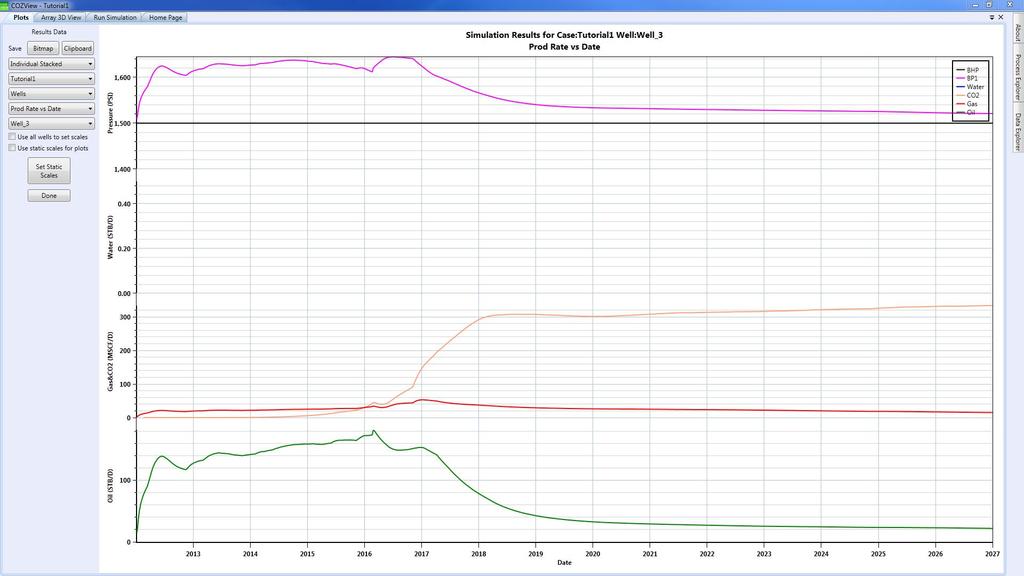
1 TUTORIAL #1 This is a 40 acre pilot test of a 5-spot pattern (10 acre well spacing) for CO2 injection in a good quality sandstone formation with a net thickness of 75 ft. Due to the small areal size the structure is relatively flat. The initial OIP was 2.75 MMSTB. There is no gas cap or associated aquifer. Well depths are approximately 5000 ft. Initial ft ss, psia 1500 Initial bubble point pressure, psia 800 Water-oil contact, ft ss NA Porosity, percent 20 Horizontal permeability, md 50 Vertical permeability, md 5 Oil gravity, API 36.3 Gas specific gravity 0.7 Reservoir Temperature, F 125 Swirr, fraction.35 Sorw, fraction.35 Sgc, fraction.03 Sorg, fraction.30 CO2 injection was initiated in 1/1/2012. The reservoir pressure was assumed to be near miscibility pressure at this time. The bottom hole injection pressure was limited to 2500 psia and the production well bottom hole pressures were not allowed to fall below 1500 psia. The maximum pilot (field) CO2 injection capacity was 1.5 MMSCF/D. The purchased CO2 was constrained at 1.2 MMSCF/D. Produced gas was not recycled. The 15 year simulation prediction resulted in a cumulative incremental oil production of 1.63 MMSTB (59.3% of OOIP). Cumulative CO2 injection was 7.5 BSCF. Cumulative CO2 production was 4.6 BSCF and 2.3 BSCF (50%) was recycled. Cumulative hydrocarbon gas production was 0.5 BSCF out of which 0.25 BSCF (50%) was recycled. 1

2 Run time was approximately 5 minute elapse time. In the course of developing the tutorial examples, some COZView screens may have changed slightly from the views shown in this document. These changes should not impact the model building and simulation process. Model Building Process The process starts with creation of a New Project. Select New Project and provide a project name on the Home Page. 2

3 Under the Process Explorer tab, select Structure in the Static Model area. The Create New Layer Structure window will appear. Input a top layer name and the net thickness (25 for this example). OK will save the information. All menus referenced in this tutorial are in the Process Explorer menu area. The model building starts with the structural surface of the productive formation. Before beginning the structural model definition, add any additional layers that are required by right-clicking the layer 1 row in the upper right of the Static Model Structure screen. Select Add New Layer and input the required data. Repeat the process as needed. In this tutorial, three layers each of thickness 25 ft. are required. 3
4 The Static Model Structure area allows the user to first Define Contours by using the resizing bars and rotation control ball. In this example the contours were not modified from the default view. Save and Continue is recommended. This is followed by Define Area Boundary (the green area shown below). The simulation model will be the area inside the green boundaries. The user selects the boundary points to reflect the reservoir area on the structure top map. 4

5 Assign Coordinates allows the user to provide coordinate positions for each of the boundary points provided. These are typically in feet as shown below. Save and Continue is recommended. 5
6 Selection of Scaled Model and Assign Elevation/Use Contours allows the user to establish the structural contour elevations. The shallowest contour elevation (smallest circle) of ft ss and the deepest contour elevation of ft ss establish the contour interval. Save and Continue is recommended. The default Minimum Cell Size displayed at the bottom of the Scaled Model area is 330 ft. Based on the model area boundary dimensions of 1320 ft by 1320 ft assigned previously, this would result in a 4 x 4 cell areal grid. For this example, which will use an injection well in the center of the area, we would prefer a 5 by 5 cell areal grid. Change the Minimum Cell Size to 250 ft and select Save and Continue. 6
7 Assign Wells allows the user to position wells on the structural surface. Once all wells are positioned their KB and TD may be defined (optional). The KB and TD data are Well KB TD Save and Continue is recommended. 7


8 Select Layer Properties 3D View to confirm the structural model and well positions in a 3D view. Layer Properties should be selected from the Static Model menu area. Values will already be input for the layers previously defined. The default units for each property are shown. The default values can be changed if appropriate. Select Done when finished to save the layer properties. 8


9 PVT should be selected from the Fluid and Saturation Properties menu area. The initial PVT properties screen will be blank. The New button should be selected to create a new set of PVT properties (table). The default values must be overridden by the user to create the PVT data shown below when the Calculate button is selected. Select Save to save the data. 9
.")
10 Saturation Functions should be selected from the Fluid and Saturation Properties menu area. The initial Saturation Function properties screen will be blank. The New button should be selected to create a new set of Saturation Function properties (table). The default values must be overridden by the user to create the Saturation Function data shown below when the Generate button is selected. Select Save to save the data. 10
11 Model Initialization should be selected from the Verify Model menu area. This screen will initially be blank. The user can verify the volumetrics of the model that has been created by inputting appropriate values in the data fields. Initially the volumetrics of the model can be checked for the original conditions, if desired. This requires identification of the Fluid PVT and Saturation Function tables previously defined. The following data should be input for the initialization (current) conditions. Initialization Date 1/1/2012 Model Type 2 phase 1500 Reference Elevation WOC (is below the model) PSATHCG 800 Selection of Initialize Model will provide the results of the volumetric calculation on the View Model Volumetrics screen. A brief view of the Simulator Runner window will appear before the volumetrics are reported. An OIP of approximately 2.75 MMSTB should be reported subject to differences in the user defined model and this example. Select Done when finished. If the user is not satisfied with the volumetric values calculated, changes to the model data created to this point can be made and saved and new volumetrics calculated. 11
12 The following steps will define well and field operating conditions for the prediction case to be run. Select Well Location from the Well Data menu area to verify previously input well locations, KB elevations and TD. This is generally informational reporting only. If additional wells are required, the user should return to the Static Model menu area and interactively locate the new well(s). KB and TD values can be change if required. Select Done to save. 12

13 Select Completions from the Well Data area to view and alter the well completions if appropriate. Initially all wells are assumed to be completed in all layers. The Active check box can be unchecked for any well layer completion, if desired. No completion changes were made to the default values for this example. It is important to keep track of the dates shown in the various well and field control screens. These must be consistent with the Initialization Date (start date for the prediction simulation run). These dates should be changed if necessary. If any changes are made to the well completions select Done to save. 13
14 Select Well Constraints from the Prediction/Well Parameters menu area. This screen will initially be blank. The Batch Generate button is a fast way to input values for multiple wells. The user can input the values noted below for the Liquid Producer wells and separately for the GAS/CO2 Injection wells. Well Constraints Injection well (Well_5): Center well in the five spot Maximum Bottom hole pressure (psia) 2500 Maximum CO2 Injection rate (MSCF/day) 5000 Producers (Well_1 Well_4) Minimum BHP (psia) 1500 Maximum Production Liquid rate (STB/day) 400 Select Done to save. 14
15 Select Well Limits from the Prediction/Well Parameters menu area. This screen will initially be blank. The Batch Generate button is a fast way to input values for multiple wells. Well limits Minimum Oil rate (STB/day) 5 Action to take Close well Select Done to save. 15
16 Select Field (Facility) Controls from the Prediction Period/Field Parameters menu area. Select New to establish the Effective Date (start date for Field Controls) and the Injection Gas Type. Please note that the default Injection Gas Type is CO2 gas. In this tutorial it is required to select CO2 as Injection Gas Type. Select OK to continue. 16

17 Field Controls Maximum Field Gas Injection Constraint (MSCF/day) 1500 Field Gas Reinjection Fraction 0.5 Available External Injection gas (MSCF/day) 1200 Select Done to save. 17
18 Select Limits from the Prediction Period/Field Parameters menu area. Check the Active box and input appropriate values. It is always wise to have a field limit specified such that the simulation run will stop when the field limit is reached. Select Done to save. It is prudent at this stage to return to the various well and field parameter screen to insure that data, particularly dates, are set appropriately. 18
19 Select Run Simulation. The Model Initialization date will be shown in the Start Date box. If this is not correct, return to the Model Initialization screen and reset the date and save. The user must provide a value in the End Date box. This must be at least one month after the Start Date. The End Date for this example is 1/1/2027. Select Go to initiate the simulation run. The Simulator Runner window will appear and update the CPU activity for the simulation run. DO NOT close the Simulator Runner window during the simulation run. It can be minimized. Closing the Simulator runner window will stop the simulation run. DO NOT close COZView during the simulation run. It can be minimized. Closing COZView will not stop the simulation run, but the simulation results will not be loaded at the conclusion of the simulation run. DO NOT change projects in COZView during a simulation run for this same reason. DO NOT turn the computer off during the simulation run. All simulation results will be lost. Two files are created early during the simulation run which may help the user track the progress of the simulation run. These are stored in the COZView directory along with various project database and result files. The files are Projectname.COZOUT and Projectname.COZDAT. The.COZDAT file is the input data deck prepared by COZView for COZSim. The.COZOUT file reports well production and injection activity for timesteps during the simulation run. It is update frequently. Both of these files can be opened with a Text editor. The.COZDAT file can be reviewed to assure that the data deck is setup as 19

20 the user anticipated. The.COZOUT file can be reviewed as the simulation run progresses. If the results are not as anticipated the run can be stopped in the Simulator Runner window. An example of the.cozout file at the end of this simulation run is shown below. DO NOT delete are change these files during the simulation run. If the same project is re-run with changes to some parameters, these files will be overwritten. When the Simulation Runner window disappears, the simulation run has completed. At the completion of the simulation run two small windows will appear which advise the user that the Map and PLT (plot) results are being loaded into COZView. Select Plots from the Simulation Results area. This will give the user access to various simulation plots for the wells and field. A sample of the available plots for this prediction simulation is shown below. It has been found prudent to close all menu tabs except the Home Page and save data as may be requested before selecting any of the Simulation Results menus. This assures that the plot, map and table files are refreshed and prior results are not shown in error. 20
21 21
22 22

23 23

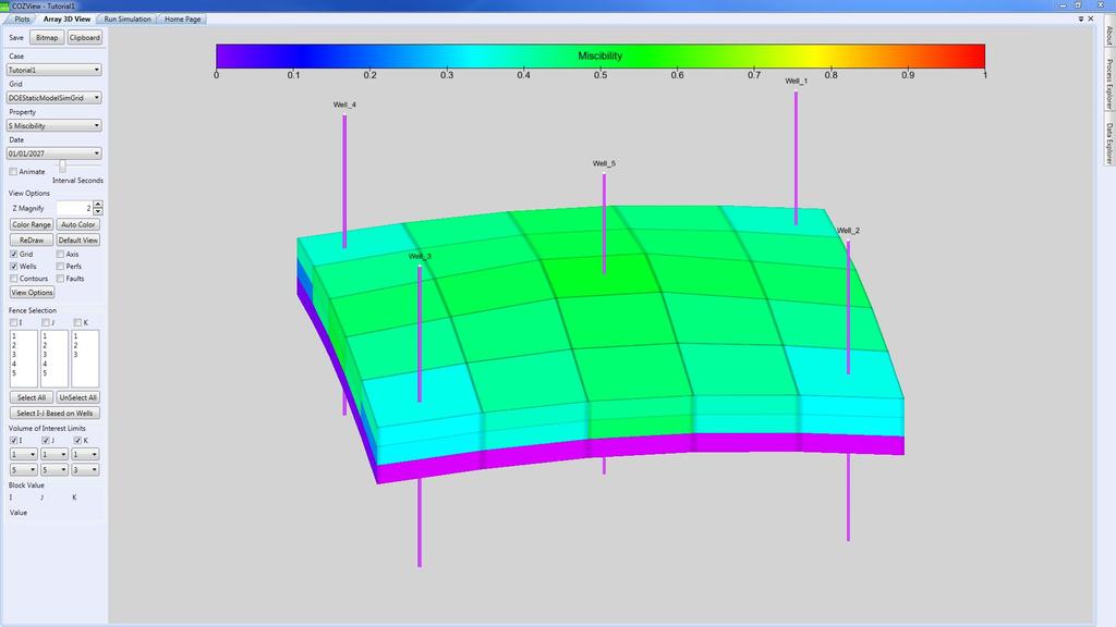
24 Select Array 3D View from the Simulation Results area. This will give the user access to various simulation maps for the field. A sample of the available maps for this prediction simulation is shown below. 24
25 25

26 26
27 The user can also select Tables from the Simulation Results area. This will provide access to tabular simulation results for wells and the field. These tables can be exported to.csv files for use in spreadsheet applications. It is also noted that any plot displays can be saved to Bitmap files or to the Clipboard for pasting into report documents. Any map displays can be saved to Bitmap files. Simulation Results The simulation results for this pilot are very interesting. First Contact miscibility was achieved (Miscibility index of 1.0) near the injection well as shown in the Miscibility map in all layers by 1/1/2015. The reservoir pressure map in Layer 1 at 1/1/2015 indicates a pressure of 1729 psia at the injection well. By 1/1/2027 the Miscibility map in Layer 1 show less than full miscibility at the injection well. This is due to a decline in the reservoir pressure. This presents the user with an opportunity to use the model to optimize the pilot performance by better management of well completions and production practices to maintain miscible conditions in the reservoir. 27
ADMS 5 MapInfo Link. User Guide CERC
 ADMS 5 MapInfo Link User Guide CERC ADMS 5 MapInfo Link User Guide November 2012 Cambridge Environmental Research Consultants Ltd 3 King s Parade Cambridge CB2 1SJ Telephone: +44 (0)1223 357773 Fax: +44
Stratigraphy Modeling Boreholes and Cross. Become familiar with boreholes and borehole cross sections in GMS
 v. 10.3 GMS 10.3 Tutorial Stratigraphy Modeling Boreholes and Cross Sections Become familiar with boreholes and borehole cross sections in GMS Objectives Learn how to import borehole data, construct a
ARCHICAD Introduction Tutorial
 Starting a New Project ARCHICAD Introduction Tutorial 1. Double-click the Archicad Icon from the desktop 2. Click on the Grey Warning/Information box when it appears on the screen. 3. Click on the Create
Example Application C H A P T E R 4. Contents
 C H A P T E R 4 Example Application This chapter provides an example application of how to perform steady flow water surface profile calculations with HEC-RAS. The user is taken through a step-by-step
Lesson 8 Tic-Tac-Toe (Noughts and Crosses)
") Lesson Game requirements: There will need to be nine sprites each with three costumes (blank, cross, circle). There needs to be a sprite to show who has won. There will need to be a variable used for switching
Lesson Game requirements: There will need to be nine sprites each with three costumes (blank, cross, circle). There needs to be a sprite to show who has won. There will need to be a variable used for switching
FlowPhase Examples Page 1 of 15. Table of Contents
 FlowPhase Examples Page 1 of 15 Table of Contents 1. VLE Flash... 2 1.1 Basic Input... 2 1.2 Entering Components... 3 1.3 Entering mol fractions... 3 1.4 Performing a flash... 4 1.5 Changing Units... 4
Stratigraphy Modeling Boreholes and Cross Sections
 GMS TUTORIALS Stratigraphy Modeling Boreholes and Cross Sections The Borehole module of GMS can be used to visualize boreholes created from drilling logs. Also three-dimensional cross sections between
Creo: Hole, Fillet, and Round Layout/Dimension Tutorial. By: Matthew Jourden Brighton High School
 Creo: Hole, Fillet, and Round Layout/Dimension Tutorial Layout of a Part with Holes 1. Open a blank drawing with your border and title block By: Matthew Jourden Brighton High School 2. Place the front,
A NEW SIMULATION OPPORTUNITY INDEX BASED SOFTWARE TO OPTIMIZE VERTICAL WELL PLACEMENTS
 A NEW SIMULATION OPPORTUNITY INDEX BASED SOFTWARE TO OPTIMIZE VERTICAL WELL PLACEMENTS FINAL PROJECT By: WARDANA SAPUTRA 12211031 Submitted in partial fulfillment of the requirements for BACHELOR OF ENGINEERING
Getting Started Guide
 SOLIDWORKS Getting Started Guide SOLIDWORKS Electrical FIRST Robotics Edition Alexander Ouellet 1/2/2015 Table of Contents INTRODUCTION... 1 What is SOLIDWORKS Electrical?... Error! Bookmark not defined.
NCSS Statistical Software
 Chapter 147 Introduction A mosaic plot is a graphical display of the cell frequencies of a contingency table in which the area of boxes of the plot are proportional to the cell frequencies of the contingency
NTL No N06 Information Requirements for EPs, DPPs and DOCDs on the OCS Effective June 18, 2010
 NTL No. 2010-N06 Information Requirements for EPs, DPPs and DOCDs on the OCS Effective June 18, 2010 Frequently Asked Questions (FAQ s) Updated July 15, 2010 Updated July 21, 2010 1. Q. What OCS areas
Modeling Basic Mechanical Components #1 Tie-Wrap Clip
 Modeling Basic Mechanical Components #1 Tie-Wrap Clip This tutorial is about modeling simple and basic mechanical components with 3D Mechanical CAD programs, specifically one called Alibre Xpress, a freely
CS108L Computer Science for All Module 3 Guide NetLogo Experiments using Random Walk and Wiggle Walk
 CS108L Computer Science for All Module 3 Guide NetLogo Experiments using Random Walk and Wiggle Walk Figure 1: Sample Interface for the Diffusion Lab. The screen capture above shows the required layout
GIS Module GMS 7.0 TUTORIALS. 1 Introduction. 1.1 Contents
 GMS 7.0 TUTORIALS 1 Introduction The GIS module can be used to display data from a GIS database directly in GMS without having to convert that data to GMS data types. Native GMS data such as grids and
1. Working with Bathymetry
 1. Working with Bathymetry The CMS setup for Shark River Inlet provides a succinct example for illustrating a number of methods and SMS tools that can be applied to most engineering projects. The area
Gerber Setup. Modified by Susan Riege on 4-Aug Parent page: WorkspaceManager Dialogs
 Gerber Setup Modified by Susan Riege on 4-Aug-2015 Parent page: WorkspaceManager Dialogs Other Related Resources Options for Project - Options Tab (Dialog) Generate Output Files (Dialog) Aperture (Dialog)
Getting Started. with Easy Blue Print
 Getting Started with Easy Blue Print User Interface Overview Easy Blue Print is a simple drawing program that will allow you to create professional-looking 2D floor plan drawings. This guide covers the
v. 8.0 GMS 8.0 Tutorial GIS Module Shapefile import, display, and conversion Prerequisite Tutorials None Time minutes
 v. 8.0 GMS 8.0 Tutorial Shapefile import, display, and conversion Objectives Learn how to import and display shapefiles with and without ArcObjects. Convert the shapefiles to GMS feature objects. Prerequisite
BSketchList 3D. BSoftware for the Design and Planning of Cabinetry and Furniture RTD AA. SketchList Inc.
 1 BSketchList 3D 1 BSoftware for the Design and Planning of Cabinetry and Furniture 2 RTD10000651AA 2 Overview of SketchList 3D SketchList 3D is a software program that aids woodworkers in the design and
Estimated Time Required to Complete: 45 minutes
 Estimated Time Required to Complete: 45 minutes This is the first in a series of incremental skill building exercises which explore sheet metal punch ifeatures. Subsequent exercises will address: placing
Importing and processing gel images
 BioNumerics Tutorial: Importing and processing gel images 1 Aim Comprehensive tools for the processing of electrophoresis fingerprints, both from slab gels and capillary sequencers are incorporated into
Sheet Metal OverviewChapter1:
 Sheet Metal OverviewChapter1: Chapter 1 This chapter describes the terminology, design methods, and fundamental tools used in the design of sheet metal parts. Building upon these foundational elements
EPS to Rhino Tutorial.
 EPS to Rhino Tutorial. In This tutorial, I will go through my process of modeling one of the houses from our list. It is important to begin by doing some research on the house selected even if you have
Published on Online Documentation for Altium Products (http://www.altium.com/documentation)
") Published on Online Documentation for Altium Products (http://www.altium.com/documentation) Home > Gerber Setup A New Era for Documentation Modified by Phil Loughhead on Jun 17, 2017 The Gerber Setup dialog
Published on Online Documentation for Altium Products (http://www.altium.com/documentation) Home > Gerber Setup A New Era for Documentation Modified by Phil Loughhead on Jun 17, 2017 The Gerber Setup dialog
PowerPoint 2016: Formatting Pictures. Introduction
 PowerPoint 2016: Formatting Pictures Introduction There are a variety of ways to format the pictures in your slide show. The picture tools in PowerPoint make it easy to personalize and modify the images
Objectives Learn how to import and display shapefiles in GMS. Learn how to convert the shapefiles to GMS feature objects. Required Components
 v. 10.3 GMS 10.3 Tutorial Importing, displaying, and converting shapefiles Objectives Learn how to import and display shapefiles in GMS. Learn how to convert the shapefiles to GMS feature objects. Prerequisite
Getting Started. Before You Begin, make sure you customized the following settings:
 Getting Started Getting Started Before getting into the detailed instructions for using Generative Drafting, the following tutorial aims at giving you a feel of what you can do with the product. It provides
MicroLab 500-series Getting Started
 MicroLab 500-series Getting Started 2 Contents CHAPTER 1: Getting Started Connecting the Hardware....6 Installing the USB driver......6 Installing the Software.....8 Starting a new Experiment...8 CHAPTER
Chief Architect X3 Training Series. Layers and Layer Sets
 Chief Architect X3 Training Series Layers and Layer Sets Save time while creating more detailed plans Why do you need Layers? Setting up Layer Lets Adding items to layers Layers and Layout Pages Layer
Quasi-static Contact Mechanics Problem
 Type of solver: ABAQUS CAE/Standard Quasi-static Contact Mechanics Problem Adapted from: ABAQUS v6.8 Online Documentation, Getting Started with ABAQUS: Interactive Edition C.1 Overview During the tutorial
Abaqus/CAE (ver. 6.14*) Plate/Shell Tutorial
 Plate/Shell Tutorial") Abaqus/CAE (ver. 6.14*) Plate/Shell Tutorial Problem Description The aluminum arch (E = 79 GPa, ν = 0.33) shown below is completely clamped along the flat faces. The arch supports a pressure of 100 MPa.
Abaqus/CAE (ver. 6.14*) Plate/Shell Tutorial Problem Description The aluminum arch (E = 79 GPa, ν = 0.33) shown below is completely clamped along the flat faces. The arch supports a pressure of 100 MPa.
House Design Tutorial
 Chapter 2: House Design Tutorial This House Design Tutorial shows you how to get started on a design project. The tutorials that follow continue with the same plan. When we are finished, we will have created
House Design Tutorial
 House Design Tutorial This House Design Tutorial shows you how to get started on a design project. The tutorials that follow continue with the same plan. When you are finished, you will have created a
Generative Drafting Overview What's New Getting Started User Tasks
 Generative Drafting Overview Conventions What's New Getting Started Defining the Drawing Sheet Part Drawing Opening a Part Creating a Front View Creating a Projection View Creating a Section View Creating
Getting Started with. Vectorworks Architect
 Getting Started with Vectorworks Architect Table of Contents Introduction...2 Section 1: Program Installation and Setup...6 Installing the Vectorworks Architect Program...6 Exercise 1: Launching the Program
House Design Tutorial
 House Design Tutorial This House Design Tutorial shows you how to get started on a design project. The tutorials that follow continue with the same plan. When you are finished, you will have created a
You can easily print images using the Capture NX print function. Here we will explain the process for printing
 Printing - Print Size Request How do you print images to fit on particular paper sizes. Response You can easily print images using the Capture NX print function. Here we will explain the process for printing
User Guide US AUS Avontus Software Corporation. All Rights Reserved
 User Guide Scaffold Designer is a simple but powerful scaffold drawing tool that allows the design of scaffold structures of any complexity and generates a bill of materials automatically. This guide covers
CONCEPTS EXPLAINED CONCEPTS (IN ORDER)
") CONCEPTS EXPLAINED This reference is a companion to the Tutorials for the purpose of providing deeper explanations of concepts related to game designing and building. This reference will be updated with
CONCEPTS EXPLAINED This reference is a companion to the Tutorials for the purpose of providing deeper explanations of concepts related to game designing and building. This reference will be updated with
Existing and Design Profiles
 NOTES Module 09 Existing and Design Profiles In this module, you learn how to work with profiles in AutoCAD Civil 3D. You create and modify profiles and profile views, edit profile geometry, and use styles
Abaqus CAE (ver. 6.9) Contact Tutorial
 Contact Tutorial") Abaqus CAE (ver. 6.9) Contact Tutorial Problem Description Note: You do not need to extrude the right vertical edge of the sensor. 2010 Hormoz Zareh 1 Portland State University, Mechanical Engineering
Abaqus CAE (ver. 6.9) Contact Tutorial Problem Description Note: You do not need to extrude the right vertical edge of the sensor. 2010 Hormoz Zareh 1 Portland State University, Mechanical Engineering
10.2. Scanning Document Camera Scoring. Page 1 of 5. How do I score answer sheets using a document camera? STEP 1
 Step by Step How do I score answer sheets using a document camera? STEP 1 Click on the Assessment icon in the top navigation bar. STEP 2 To locate your assessment in an assessment list, first select the
SolidWorks 95 User s Guide
 SolidWorks 95 User s Guide Disclaimer: The following User Guide was extracted from SolidWorks 95 Help files and was not originally distributed in this format. All content 1995, SolidWorks Corporation Contents
Alibre Design Tutorial: Loft, Extrude, & Revolve Cut Loft-Tube-1
 Alibre Design Tutorial: Loft, Extrude, & Revolve Cut Loft-Tube-1 Part Tutorial Exercise 5: Loft-Tube-1 [Complete] In this Exercise, We will set System Parameters first, then part options. Then, in sketch
CSiDETAILER USER S MANUAL. Detailing and Drawing of Structural Members. Computers and Structures, Inc. Berkeley, California, USA
 CSiDETAILER Detailing and Drawing of Structural Members USER S MANUAL Computers and Structures, Inc. Berkeley, California, USA Version 8.00 August 2004 COPYRIGHT The computer program CSiDETAILER and all
Designing in the context of an assembly
 SIEMENS Designing in the context of an assembly spse01670 Proprietary and restricted rights notice This software and related documentation are proprietary to Siemens Product Lifecycle Management Software
House Design Tutorial
 Chapter 2: House Design Tutorial This House Design Tutorial shows you how to get started on a design project. The tutorials that follow continue with the same plan. When you are finished, you will have
for Solidworks TRAINING GUIDE LESSON-9-CAD
 for Solidworks TRAINING GUIDE LESSON-9-CAD Mastercam for SolidWorks Training Guide Objectives You will create the geometry for SolidWorks-Lesson-9 using SolidWorks 3D CAD software. You will be working
Landscaping Tutorial. Chapter 5:
 Chapter 5: Landscaping Tutorial This tutorial was written to help you learn how to use Home Designer Landscape and Deck s Terrain tools. In this tutorial, you will learn how to add elevation information
Advance Steel. Tutorial
 Advance Steel Tutorial Table of contents About this tutorial... 7 How to use this guide...9 Lesson 1: Creating a building grid...10 Step 1: Creating an axis group in the X direction...10 Step 2: Creating
Quintic Software Tutorial 3
 Quintic Software Tutorial 3 Take a Picture 1 Tutorial 3 Take a Picture Contents Page 1. Photo 2. Photo Sequence a. Add shapes and angles 3. Export Analysis 2 Tutorial 3 Take a Picture 1. Photo Open the
Version 6.1. Instructional Days: 11-14
 Instructional Days: 11-14 Topic Description: In this lesson, students learn how computers can be used as a tool for visualizing data, modeling and design, and art in the context of culturally situated
PHAUCET 2012 version
 PHAUCET 2012 version 8.2.20 User Manual www.uaex.edu DISCLAIMER Although the PHAUCET program has been tested by its developers, NO warranty, expressed or implied, is made as to the accuracy and functionality
Batch Processing Converting images in a folder to JPEG
 Batch Processing Converting images in a folder to JPEG Request I would like to convert multiple RAW images (NEF files) to JPEG images all at once Response You can use a Batch Process to convert all RAW
CPM Educational Program
 CC COURSE 2 ETOOLS Table of Contents General etools... 5 Algebra Tiles (CPM)... 6 Pattern Tile & Dot Tool (CPM)... 9 Area and Perimeter (CPM)...11 Base Ten Blocks (CPM)...14 +/- Tiles & Number Lines (CPM)...16
1 Sketching. Introduction
 1 Sketching Introduction Sketching is arguably one of the more difficult techniques to master in NX, but it is well-worth the effort. A single sketch can capture a tremendous amount of design intent, and
How to Make a Run Chart in Excel
 How to Make a Run Chart in Excel While there are some statistical programs that you can use to make a run chart, it is simple to make in Excel, using Excel s built-in chart functions. The following are
midas Dshop (Basic Tutorial) Basic Tutorial Reinforced Concrete Structure - 1 -
 Basic Tutorial Reinforced Concrete Structure - 1 -") midas Dshop (Basic Tutorial) midas DrawingShop Basic Tutorial Reinforced Concrete Structure - 1 - Index Ch.1 Summary of Design 1. Summary of Building Model 2. Standards of Structural Design 3. Structural
midas Dshop (Basic Tutorial) midas DrawingShop Basic Tutorial Reinforced Concrete Structure - 1 - Index Ch.1 Summary of Design 1. Summary of Building Model 2. Standards of Structural Design 3. Structural
Chapter 6: TVA MR and Cardiac Function
 Chapter 6 Cardiac MR Introduction Chapter 6: TVA MR and Cardiac Function The Time-Volume Analysis (TVA) optional module calculates time-dependent behavior of volumes in multi-phase studies from MR. An
Tinker Tuesday Project - Wood Book Covers
 Tinker Tuesday Project - Wood Book Covers 1. On the laser engraver computer, click on the folder icon on the task bar. Then, select Thaw Space and open the document titled Living Hinge Template. 2. Measure
Sheet Metal Punch ifeatures
 Lesson 5 Sheet Metal Punch ifeatures Overview This lesson describes punch ifeatures and their use in sheet metal parts. You use punch ifeatures to simplify the creation of common and specialty cut and
Generations Automatic Stand-Alone Lace By Bernie Griffith Generations Software
 We are going to create an open Italian lace. Generations software products provide advanced image processing features allowing for the creation of stand-alone lace with just a few simple techniques. A
CONTENT INTRODUCTION BASIC CONCEPTS Creating an element of a black-and white line drawing DRAWING STROKES...
 USER MANUAL CONTENT INTRODUCTION... 3 1 BASIC CONCEPTS... 3 2 QUICK START... 7 2.1 Creating an element of a black-and white line drawing... 7 3 DRAWING STROKES... 15 3.1 Creating a group of strokes...
PASS Sample Size Software. These options specify the characteristics of the lines, labels, and tick marks along the X and Y axes.
 Chapter 940 Introduction This section describes the options that are available for the appearance of a scatter plot. A set of all these options can be stored as a template file which can be retrieved later.
Use the and buttons on the right to go line by line, or move the slider bar in the middle for a quick canning.
 How To Use The IntelliQuilter Help System The user manual is at your fingertips at all times. Extensive help messages will explain what to do on each screen. If a help message does not fit fully in the
House Design Tutorial
 Chapter 2: House Design Tutorial This House Design Tutorial shows you how to get started on a design project. The tutorials that follow continue with the same plan. When you are finished, you will have
v Introduction Images Import images in a variety of formats and register the images to a coordinate projection WMS Tutorials Time minutes
 v. 10.1 WMS 10.1 Tutorial Import images in a variety of formats and register the images to a coordinate projection Objectives Import various types of image files from different sources. Learn how to work
LSM 780 Confocal Microscope Standard Operation Protocol
 LSM 780 Confocal Microscope Standard Operation Protocol Basic Operation Turning on the system 1. Sign on log sheet according to Actual start time 2. Check Compressed Air supply for the air table 3. Switch
Creo Revolve Tutorial
 Creo Revolve Tutorial Setup 1. Open Creo Parametric Note: Refer back to the Creo Extrude Tutorial for references and screen shots of the Creo layout 2. Set Working Directory a. From the Model Tree navigate
Tinker Tuesday Project - Drinking Glasses
 Tinker Tuesday Project - Drinking Glasses 1. Open CorelDRAW and create a new document. Near the top left corner of the screen, click File, and then click Import on the resulting menu. Select an image from
Vectorworks Architect
 SAMPLE by Jonathan Pickup third edition written with version 2011 Vectorworks Architect Tutorial Manual Table of Contents Introduction... iii How to Use this Manual... iii New Ways of Drawing... iv Vectorworks
Using Siemens NX 11 Software. The connecting rod
 Using Siemens NX 11 Software The connecting rod Based on a Catia tutorial written by Loïc Stefanski. At the end of this manual, you should obtain the following part: 1 Introduction. Start NX 11 and open
CBCL Limited Sheet Set Manager Tutorial 2013 REV. 02. CBCL Design Management & Best CAD Practices. Our Vision
 CBCL Limited Sheet Set Manager Tutorial CBCL Design Management & Best CAD Practices 2013 REV. 02 Our Vision To be the most respected and successful Atlantic Canada based employeeowned firm, delivering
Engineering 3821 Fall Pspice TUTORIAL 1. Prepared by: J. Tobin (Class of 2005) B. Jeyasurya E. Gill
 B. Jeyasurya E. Gill") Engineering 3821 Fall 2003 Pspice TUTORIAL 1 Prepared by: J. Tobin (Class of 2005) B. Jeyasurya E. Gill 2 INTRODUCTION The PSpice program is a member of the SPICE (Simulation Program with Integrated Circuit
Engineering 3821 Fall 2003 Pspice TUTORIAL 1 Prepared by: J. Tobin (Class of 2005) B. Jeyasurya E. Gill 2 INTRODUCTION The PSpice program is a member of the SPICE (Simulation Program with Integrated Circuit
Revit Structure 2012 Basics:
 SUPPLEMENTAL FILES ON CD Revit Structure 2012 Basics: Framing and Documentation Elise Moss autodesk authorized publisher SDC PUBLICATIONS www.sdcpublications.com Schroff Development Corporation Structural
Hettich Atira User Guide.
 Hettich Atira User Guide. Introduction Overview The Hettich Atira Drawer Package from Solid Setup adds the Hettich Atira drawers to Cabinet Vision Solid. It provides drilling for the drawer box parts,
Getting Started with. Vectorworks Architect
 Getting Started with Vectorworks Architect Table of Contents Introduction...2 Section 1: Program Installation and Setup...6 Installing the Vectorworks Architect Program...6 Exercise 1: Launching the Program
Advance Concrete. Tutorial
 Advance Concrete Tutorial Table of contents About this tutorial... 9 How to use this guide... 10 Lesson 1: Creating a building grid... 11 Step 1: Create a default building grid... 11 Step 2: Set the distances
1 ImageBrowser Software User Guide 5.1
 1 ImageBrowser Software User Guide 5.1 Table of Contents (1/2) Chapter 1 What is ImageBrowser? Chapter 2 What Can ImageBrowser Do?... 5 Guide to the ImageBrowser Windows... 6 Downloading and Printing Images
SpeedMark Tutorial 4 Using the rotary indexer
 Using the rotary indexer SpeedMark Tutorial 4 for SpeedMarker Series V001_SM-Tutorial (08/2015) ENGLISH Content Content 1 Objectives of this tutorial... 3 2 Mechanical setup... 4 3 Software setup... 5
The Revolve Feature and Assembly Modeling
 The Revolve Feature and Assembly Modeling PTC Clock Page 52 PTC Contents Introduction... 54 The Revolve Feature... 55 Creating a revolved feature...57 Creating face details... 58 Using Text... 61 Assembling
Using Dynamic Views. Module Overview. Module Prerequisites. Module Objectives
 Using Dynamic Views Module Overview The term dynamic views refers to a method of composing drawings that is a new approach to managing projects. Dynamic views can help you to: automate sheet creation;
Page 21 GRAPHING OBJECTIVES:
 Page 21 GRAPHING OBJECTIVES: 1. To learn how to present data in graphical form manually (paper-and-pencil) and using computer software. 2. To learn how to interpret graphical data by, a. determining the
Harn Impaz Visual User Guide.
 Harn Impaz Visual User Guide. Introduction Overview The Harn Impaz Visual Package from Solid Setup adds the White Harn Impaz Standard drawers and Inner drawers (Rollouts), and the Harn Impaz Office (Black)
LAB 2: Sampling & aliasing; quantization & false contouring
 CEE 615: Digital Image Processing Spring 2016 1 LAB 2: Sampling & aliasing; quantization & false contouring A. SAMPLING: Observe the effects of the sampling interval near the resolution limit. The goal
Module 2.1, 2.2 Review. EF101 Analysis & Skills Module 2.3. Sketched Features and Operations. On-line Help Two Locations
 EF101 Analysis & Skills Module 2.3 Engineering Graphics Revolved Features Placed Features Work Features Module 2.1, 2.2 Review What are the three types of operations for adding features to the base feature?
Hydraulics and Floodplain Modeling Managing HEC-RAS Cross Sections
 v. 9.1 WMS 9.1 Tutorial Hydraulics and Floodplain Modeling Managing HEC-RAS Cross Sections Modify cross sections in an HEC-RAS model to use surveyed cross section data Objectives Build a basic HEC-RAS
Introduction. Basic Image Formatting. PowerPoint 2010 Formatting Pictures. To Crop an Image: Page 1
 PowerPoint 2010 Formatting Pictures Introduction Page 1 Once you've added pictures to your presentations, you can format them in various ways. The picture tools in PowerPoint 2010 make it easy to incorporate
Step 1: Set up the variables AB Design. Use the top cells to label the variables that will be displayed on the X and Y axes of the graph
 Step 1: Set up the variables AB Design Use the top cells to label the variables that will be displayed on the X and Y axes of the graph Step 1: Set up the variables X axis for AB Design Enter X axis label
Autodesk Advance Steel. Drawing Style Manager s guide
 Autodesk Advance Steel Drawing Style Manager s guide TABLE OF CONTENTS Chapter 1 Introduction... 5 Details and Detail Views... 6 Drawing Styles... 6 Drawing Style Manager... 8 Accessing the Drawing Style
Introduction. Basic Image Formatting. Word 2010 Formatting Pictures. To Crop an Image: Page 1
 Word 2010 Formatting Pictures Introduction Page 1 Once you've added pictures to your documents, you can format them in various ways. The picture tools in Word 2010 make it easy to incorporate images into
Hafele Alto Visual User Guide.
 Hafele Alto Visual User Guide. Introduction Overview The Hafele Alto Visual Package from Solid Setup adds the Hafele Alto drawers to Cabinet Vision Solid. It provides drilling for the drawer box parts,
GCS Member Photo & Image Editor
 GCS Member Photo & Image Editor Golf Computer Systems Image Editor Version 1.12.8.00 31 August 2010 Introduction The Golf Computer Systems Membership Management System (MMS) and FACTS (Facility and Activity
MRI Grid. The MRI Grid is a tool in MRI Cell Image Analyzer, that can be used to associate measurements with labeled positions on a board.
 Abstract The is a tool in MRI Cell Image Analyzer, that can be used to associate measurements with labeled positions on a board. Illustration 2: A grid on a binary image. Illustration 1: The interface
Converting a 3D object into a mould. With Tinkercad and Inkscape
 Converting a 3D object into a mould With Tinkercad and Inkscape What you need Tinkercad Inkscape a STL file to convert Create an account now Download for free now Pick up one for free now To make better
inphoto ID SLR Automatic ID photography With Canon SLR camera User Guide
 inphoto ID SLR Automatic ID photography With Canon SLR camera User Guide 2014 Akond company Phone/fax: +7(812)384-6430 Cell: +7(921)757-8319 e-mail: info@akond.net akondsales@gmail.com http://www.akond.net
Excel Lab 2: Plots of Data Sets
 Excel Lab 2: Plots of Data Sets Excel makes it very easy for the scientist to visualize a data set. In this assignment, we learn how to produce various plots of data sets. Open a new Excel workbook, and
Release Highlights for BluePrint-PCB Product Version 1.8
 Release Highlights for BluePrint-PCB Product Version 1.8 Introduction BluePrint Version 1.8 Build 341 is a rolling release update. BluePrint rolling releases allow us to be extremely responsive to customer
CHM 152 Lab 1: Plotting with Excel updated: May 2011
 CHM 152 Lab 1: Plotting with Excel updated: May 2011 Introduction In this course, many of our labs will involve plotting data. While many students are nerds already quite proficient at using Excel to plot