POWER CAGE CLAMP High-Current Terminal Blocks for Conductors up to 350 kcmil (185 mm 2 )
|
|
|
- Maximillian Hamilton
- 5 years ago
- Views:
Transcription


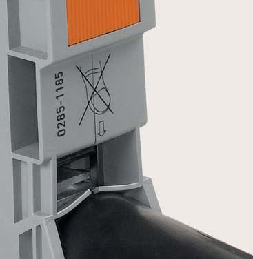


1 POWER CAGE CLAMP High-Current Terminal Blocks for Conductors up to 350 kcmil (185 mm 2 ) vibration-proof fast maintenance-free
.")
2 WAGO BENEFITS Using springs instead of screws is the key to WAGO s success. The POWER CAGE CLAMP provides the appropriate clamping force for conductors up to 2, 2/0, 4/0 AWG and 350 kcmil (35, 50, 95 and 185 mm 2 ). The Latest and Largest Member of our High-Current Family Connects: For more information visit 1/0 to 350 kcmil 310 A Up to 1000 VAC/DC 2

3 Suitable for Every Application Meets the most stringent requirements, including those applications. Heat- and cold-resistant even under the heaviest of loads Always Reliable Optimum clamping force independent of operator skill 100% reliable with vibration-proof, thermal cycling resistant, gas-tight connections Fast Termination Easy to Use Side conductor entry Orange locking tab keeps the clamp open for hands-free wiring Industry s widest range of accessories to get the job done Eliminate time-consuming preparation no ring terminals or ferrules required No expensive torque wrenches or calibration required Up to 60% faster than wiring with screw terminal blocks Vibration-Proof Fast Maintenance-Free No retightening of screws wire it once and forget it 3


4 OUR POWER TEAM Terminate Conductors up to 350 kcmil (185 mm 2 ) with Just One Turn Grounding Green/yellow terminal blocks easily identify ground function Metal snap-on mounting foot ensures the proper ground connection without the use of screws. Continuous Marking Strip Marking Marking Tags Continuous marking strip installed with a quick swipe of the thumb Marking tags installed individually above the orange locking tab Marking carrier supplements the use of tag and strip marking Conductor Termination Rotate the operating tool counterclockwise to the stop!. Next, push in the orange locking tab for hands-free wiring. Insert a stripped conductor until it hits the backstop. Hold in this position. A short counterclockwise rotation " releases the tab. The operating tool then rotates clockwise, securely clamping the conductor. 4


5 Safety Protective Warning Covers Provides visual indication for high-voltage applications and prevents access to conductor clamping mechanism as well as built-in test point Finger Guards Yellow, detachable shock protectors for unused jumper slots or conductor entries Power Tap (for 2 AWG 350 kcmil) Easy to install, space saving power tap, with marking tag holder, allows for convenient power distribution to additional loads Commoning Testing For 2 AWG Convenient push-in adjacent jumper allows for easy potential commoning. Independent jumper slots allow continuous commoning beyond two terminal blocks. For 2/0, 4/0 and 350 kcmil Comb style jumper provides convenient potential commoning. Dual jumper slot allows for max rated conductor no conductor size derating required.. Via Step-Down Jumpers with TOPJOB S Push-in, step-down distribution from 2 AWG (POWER CAGE CLAMP ) to 20-4 AWG ( Series TOPJOB S terminal blocks). Easy troubleshooting via 4 mm Ø touch-proof test plug. Use a test plug adapter ( ) for 2 AWG terminal blocks. 5


6 285 SERIES DIN RAIL MOUNT 2 AWG (35 mm 2 ) 2/0 AWG (50 mm 2 ) Conductor cross-section 8 2 AWG (6 35 mm 2) 8 2 AWG (6 35 mm 2 ) 8 2/0 AWG (10 50 (70 f-st ) mm 2 ) Rated voltage/current 880 V, 115 A U 600 V, 115 A V, 125 A EN 880 V, 150 A U 600 V, 150 A V, 150 A EN Terminal block width Strip length 16 mm/0.63 in. L 25 mm/0.98 in. 16 mm/0.63 in. L 25 mm/0.98 in. 20 mm/0.79 in. L 30 mm/1.18 in. Image Item Numbers through terminal block Only suitable for DIN 35 x 15 rails ground terminal block / Only suitable for DIN 35 x 15 rails; 2.3 mm thick through terminal block Only suitable for DIN 35 x 15 rails Accessories Adjacent jumper (l N 85 A) (l N 150 A for 1 jumper, l N 130 A for 2 4 jumpers) Step-down jumper (l N 90 A) Power tap (1x AWG) (600 V, 30 A U / 800 V, 32 A EN) (2x AWG) (600 V, 30 A U / 1000 V, 41 A EN) Current and Voltage Transformer Tap Warning cover Finger guard Operating tool (type 3, 5.5 x 0.8 mm screwdriver blade) (Allen-wrench) Marking Accessories Marking strips (plain, white, 11 mm wide, 50 m reel) (plain, white, 11 mm wide, 50 m r Requires use of marker carrier WMB Inline markers (plain, white, 1500 markers, stretchable mm) (plain, white, 1500 markers, str WMB Multi marking system (plain, white, 10 strips with 10 markers per card, stretchable mm) (plain, white, 10 strips with 10 m stretchable mm) Marker carrier For more technical data, see our Full Line Catalog, Volume 1 or visit 6
 600 V, 200 A U 600 V, 200 A 2 1000 V, 232 A EN 1000 V, 310 A U 1000 V, 310 A 2 1000 V, 353 A EN 20 mm/0.79 in. L 30 mm/1.18 in. 25 mm/0.98 in. L 35 mm/1.38 in. 25 mm/0.98 in. L 35 mm/1.38 in. 32 mm/1.")


 (600 V, 50 A U / 1000 V, 57 A EN) 285-1175 (1x24.")
 Requires use of marker carrier 2009-110 (plain, white, 11 mm wide, 50 m reel) etchable 5 5.")
7 4/0 AWG (95 mm 2 ) 350 kcmil (185 mm 2 ) 8 2/0 AWG (10 50 (70 f-st ) mm 2 ) 4 4/0 AWG (25 95 mm 2 ) 4 4/0 AWG (25 95 mm 2 ) 1/0 AWG 350 kcmil ( mm 2 ) 1/0 AWG 350 kcmil ( mm 2 ) 600 V, 200 A U 600 V, 200 A V, 232 A EN 1000 V, 310 A U 1000 V, 310 A V, 353 A EN 20 mm/0.79 in. L 30 mm/1.18 in. 25 mm/0.98 in. L 35 mm/1.38 in. 25 mm/0.98 in. L 35 mm/1.38 in. 32 mm/1.26 in. L mm/ in 32 mm/1.26 in. L mm/ in ground terminal block / Only suitable for DIN 35 x 15 rails; 2.3 mm thick, copper through terminal block Only suitable for DIN 35 x 15 rails ground terminal block / Only suitable for DIN 35 x 15 rails; 2.3 mm thick, copper through terminal block * 1 Only suitable for DIN 35 x 15 rails ground terminal block / * 1 Only suitable for DIN 35 x 15 rails; 2.3 mm thick, copper (l N 232 A for 1 jumper, l N 192 A for 2 4 jumpers) (l N 309 A for 1 jumper) (2x AWG) (600 V, 50 A U / 1000 V, 57 A EN) (1x AWG) (600 V, 50 A U / 1000 V, 57 A EN) / (250 A / 1 A Current Transformer) (Allen-wrench) (Allen-wrench) eel) (plain, white, 11 mm wide, 50 m reel) Requires use of marker carrier (plain, white, 11 mm wide, 50 m reel) etchable mm) (plain, white, 1500 markers, stretchable mm) (plain, white, 1500 markers, stretchable mm) arkers per card, (plain, white, 10 strips with 10 markers per card, stretchable mm) (plain, white, 10 strips with 10 markers per card, stretchable mm) These items have hazardous locations approvals - IECEx, ATEX, Class I, Zone 0. * Pending 7

 high-current, rail mounted")


8 WAGO HIGH CURRENT BLOCKS WITH MOUNTING FLANGES WAGO s 2/0, 4/0, and 350 kcmil (50 mm², 90 mm² and 185 mm²) high-current, rail mounted terminal blocks are also available for direct installation on a sub-panel or mounting plate. The same accessories can be used for both the panel mount and rail mount versions. For more information visit 8

9 Versions for functional ground in gray-yellow housing Nominal current: 310 A Rated voltage: up to 1000 VAC/DC Mount a 350 kcmil terminal block directly onto the plate Vibration-Proof Fast Maintenance-Free 9


10 INSTALLATION 1. First, insert coupling elements into housing slots. 2. Then, connect and align the terminal blocks. 3. Secure the terminal block to a mounting plate using two M8 cylinder-head screws and appropriate washers. The Panel Mount Versions are the Newest Edition The same reliable, vibration-proof, and maintenance-free connection as the DIN-rail mount POWER CAGE CLAMP 10
 mm 2 ) 880 V, 150 A U 600 V, 150 A 2 1000 V, 150 A EN 4... 4/0 AWG (25 95 mm 2 ) 600 V, 200 A U 600 V, 200 A 2 1000 V, 232 A EN 1/0 AWG.")

 285-495 (l N 232 A for 1 jumper, l N 192 A for 2... 4 jumpers) 285-1171 (l N 309 A for 1 jumper) Power tap 285-447 (2 x 24.")
11 285 SERIES WITH MOUNTING FLANGES 2/0 AWG (50 mm²) 4/0 AWG (95 mm²) 350 kcmil (185 mm²) Conductor cross-section Rated voltage/current /0 AWG (10 50 (70 f-st ) mm 2 ) 880 V, 150 A U 600 V, 150 A V, 150 A EN /0 AWG (25 95 mm 2 ) 600 V, 200 A U 600 V, 200 A V, 232 A EN 1/0 AWG kcmil ( mm 2 ) 1000 V, 310 A U 1000 V, 310 A V, 353 A EN Terminal block width Strip length 20 mm/0.79 in. L 30 mm/1.18 in. 25 mm/1.98 in. L 35 mm/1.38 in. 32 mm/1.26 in. L mm/ in. Image Item Numbers through terminal block through terminal block through terminal block Accessories Adjacent jumper (l N 150 A for 1 jumper, l N 130 A for jumpers) (l N 232 A for 1 jumper, l N 192 A for jumpers) (l N 309 A for 1 jumper) Power tap (2 x AWG) (600 V, 30 A U / 1000 V, 41 A EN) (2 x AWG) (600 V, 50 A U / 1000 V, 57 A EN) (2 x AWG) (600 V, 50 A U / 1000 V, 57 A EN) Current and voltage transformer tap / (250 A / 1 A Current Transformer) Coupling element Warning cover Finger guard Operating tool Marking Accessories Marking strips (plain, white, 11 mm wide, 50 m reel) WMB Inline markers (plain, white, 1500 markers, stretchable mm) WMB Multi marking system (plain, white, 10 strips with 10 markers per card, stretchable mm) Marker Carrier For more technical data, see our Full Line Catalog, Volume 1, or visit 11
12 WAGO Corporation N120 W19129 Freistadt Road Germantown, Wisconsin Telephone: 800 / DIN Rail ( ) Fax: 262 / info.us@wago.com Canada WAGO Corporation Tel. 800/DIN Rail ( ) Fax 262/ Mexico WAGO Corporation Queretaro Tel. 001/800/309/ /442/221/5946 Fax + 52/442/221/ WAGO is a registered trademark of WAGO Verwaltungsgesellschaft mbh. Copyright WAGO Kontakttechnik GmbH & Co. KG all rights reserved. The content and structure of the WAGO Websites, catalogs, videos, and other WAGO media are subject to copyright. The dissemination or changing of the content of these pages and videos is not permitted. Furthermore, the content may neither be copied nor made available to third parties for commercial purposes. Also subject to copyright are the images and videos that were made available to WAGO Kontakttechnik GmbH & Co. KG by third parties / MM² POWER CC 1.1 US 09/2016 Printed in the United States Subject to design changes
POWER CAGE CLAMP High-Current Terminal Blocks for Conductors up to 350 kcmil (185 mm 2 )
") POWER CAGE CLAMP High-Current Terminal Blocks for Conductors up to 350 kcmil (185 mm 2 ) vibration-proof fast maintenance-free WAGO BENEFITS Using springs instead of screws is the key to WAGO s success.
POWER CAGE CLAMP High-Current Terminal Blocks for Conductors up to 350 kcmil (185 mm 2 ) vibration-proof fast maintenance-free WAGO BENEFITS Using springs instead of screws is the key to WAGO s success.
ELECTRICAL INSTALLATION PRODUCTS Splicing Connectors and Chassis Mount Terminal Blocks
 ELECTRICAL INSTALLATION PRODUCTS Splicing Connectors and Chassis Mount Terminal Blocks 221 SERIES LEVER-NUTS The Next Generation of Compact Splicing Connectors 221 SERIES LEVER-NUTS The Difference is Clear:
Switching relay terminal block; Relay with 1 changeover contact (1u); with miniature switching relay
; with miniature switching relay") relay - Item No: 89-304 Switching relay terminal block; Relay with changeover contact (u); with miniature switching relay Item No: 89-304 Switching relay terminal block; Relay with changeover contact (u);
relay - Item No: 89-304 Switching relay terminal block; Relay with changeover contact (u); with miniature switching relay Item No: 89-304 Switching relay terminal block; Relay with changeover contact (u);
Through and Ground Conductor Terminal Blocks 290 Series
 11 474 Through and Ground Conductor Terminal Blocks 290 Series 0.34-1. mm"f-st" 0.31-1 mm"s" 1 00 V/6 kv/3 2 1 AWG 22-16"f-st" AWG 22-18"s" I N 13. A Terminal block width mm / 0.197 in 0.34-1. mm"f-st"
WINSTA The Connection System. Full Line Catalog 2010/2011
 WINSTA The Connection System Full Line Catalog 2010/2011 5 WAGO Registered Trademarks CAGE CLAMP CAGE CLAMP @ POWER CAGE CLAMP FIT CLAMP PUSH WIRE TOPJOB TOPJOB @ WINSTA WAGO X-COM X-COM @ JUMPFLEX TO-PASS
EPSITRON Electronic Circuit Breakers Compact and Precise ECBs for DC Circuits
 EPSITRON Electronic Circuit Breakers Compact and Precise ECBs for DC Circuits WHY SECONDARY-SIDE FUSE PROTECTION? On the secondary side, switchedmode power supplies provide DC voltage to control circuit
Reflow Technology Product Overview
 Reflow Technology Product Overview THR COMPONENT REQUIREMENTS THR Components Components for THR (Through-Hole Reflow) soldering must withstand higher temperatures than those found in standard wave soldering.
EPSITRON Advanced Power Supply System Innovations
 EPSITRON Advanced Power Supply System Innovations EPSITRON COMPACT POWER Technical Data L H W Item Number 787-1202 787-1212 Nominal input voltage 100... 240 VAC 100... 240 VAC Input voltage range 90...
Operating tools. with partially insulated shaft Type 1, 2 and 3 in set
 Accessories 40 Accessories 41 Operating Tools 42 45 Operating Tools WINSTA 46 47 Disconnection Tools 48 Cable Strippers 500 Wire Strippers 501 Cable Cutters 502 Crimping Tools 502 503 Test and Measurement
JUMPFLEX 857 Series ma ma V. Signal Conditioning/Relay and Solid State Modules
 JUMPFLEX Series Signal Conditioning/Relay and Solid State Modules...0 V 0...0 ma...0 ma JUMPFLEX Series Today s factory automation and process control applications require conversion, isolation, and transmission
Printview: 4-channel analog input module; 4-20 ma; Single-ended - Item No.:
 Printview: 4-channel analog input module; 4-20 ma; Single-ended - Item No: 70-4 4-channel analog input module; 4-20 ma; Single-ended Item No: 70-4 4-channel analog input module; 4-20 ma; Single-ended Marking
8-channel digital input module; 24 VDC; 3.0 ms; high-side switching; 1-conductor connection
 Printview: 8-channel digital input module; 24 VDC; 30 ms; high-side switching; -conductor connection - Item No: 70-430 8-channel digital input module; 24 VDC; 30 ms; high-side switching; -conductor connection
Current and Energy Measurement Technology Efficiency Is That Easy! Product Overview
 Current and Energy Measurement Technology Efficiency Is That Easy! Product Overview Content WAGO Energy Management 4 Current Transformers Selection Guide 8 Power and Energy Measurement 10 Voltage Taps
MULTI CONNECTION SYSTEM. Product Overview
 MULTI CONNECTION SYSTEM Product Overview THE ENTIRE RANGE OF MCS CONNECTORS MICRO Pin spacing: 2. mm Conductor sizes: 0.08 0. mm 2 (28 20 AWG) The Most Compact MCS MICRO Connector System with CAGE CLAMP
PHOENIX CONTACT
 Electronic circuit breaker CLIPLINE Data sheet 102898_en_03 PHOENIX CONTACT 2010-12-17 1 Description The electronic circuit breaker can be used in applications that cover all aspects of the switched-mode
PHOENIX CONTACT
 Selective circuit breaker CLIPLINE Data sheet 100464_en_05 PHOENIX CONTACT 2009-11-17 1 Description The electronic circuit breaker, which has a design width of just 12.5 mm, selectively protects all 24
Q-Zone Hoop-Frame. Assembly Instructions. Copyright July 11, 2018 Grace Company (Reproduction Prohibited) Version 1.8
 Version 1.8") Q-Zone Hoop-Frame Assembly Instructions Copyright July 11, 2018 Grace Company (Reproduction Prohibited) Version 1.8 Table of Contents Table of Contents... i Warranty... ii Parts List Box 1...iii Box 2...
Q-Zone Hoop-Frame Assembly Instructions Copyright July 11, 2018 Grace Company (Reproduction Prohibited) Version 1.8 Table of Contents Table of Contents... i Warranty... ii Parts List Box 1...iii Box 2...
REC Series Rack Installation Guide
 REC Series Rack Installation Guide 1 REC Series Rack Installation Guide TABLE OF CONTENTS SECTION SAFETY WARNINGS 1 600 WIDE EXPLODED VIEW 2 800 WIDE EXPLODED VIEW 3 SWITCHING DOOR HANDING 4 STABILIZING
Sockets. SU Series: DIN Rail Snap-Mount Sockets. F-6 USA: (800) 262-IDEC or (408) , Canada: (888) 317-IDEC ➀➁➄➅ ➁➂➃➄
 262-IDEC or (408) , Canada: (888) 317-IDEC ➀➁➄➅ ➁➂➃➄") SU Series: DIN Rail Snap-Mount SU Series: DIN Rail Snap-Mount SUS-L SUS-L -blade DIN-mount/surface mount -blade DIN-mount/surface mount Spring clamp terminals Spring clamp terminals - AWG - AWG 0A A (using
SU Series: DIN Rail Snap-Mount SU Series: DIN Rail Snap-Mount SUS-L SUS-L -blade DIN-mount/surface mount -blade DIN-mount/surface mount Spring clamp terminals Spring clamp terminals - AWG - AWG 0A A (using
MANUAL e130. Wallstation
 MANUAL 07.29.13 e130 Wallstation The Enovate Medical e130 Wallstation was designed to set a new standard in quality. Enovate Medical s goal is to provide a wallstation that is ready for years of use,
Copyright Black Box Corporation. All rights reserved Park Drive Lawrence, PA Fax
 Copyright 2003. Black Box Corporation. All rights reserved. 1000 Park Drive Lawrence, PA 15055-1018 724-746-5500 Fax 724-746-0746 JULY 2003 RM3010A RM315-R2 RM323-R2 RM329 RM451 RM457 RM3020A RM316 RM324-R2
M14 MODULAR CHASSIS SYSTEM (MOD 1) INSTRUCTION MANUAL. West Springfield, MA Phone: (866) FAX: (413)
 INSTRUCTION MANUAL. West Springfield, MA Phone: (866) FAX: (413)") M14 MODULAR CHASSIS SYSTEM (MOD 1) INSTRUCTION MANUAL Troy Industries, Inc. WWW.TROYIND.COM West Springfield, MA 01089 Phone: (866) 788-6412 FAX: (413) 383-0339 Thank You M14/M1A MODULAR CHASSIS SYSTEM
M14 MODULAR CHASSIS SYSTEM (MOD 1) INSTRUCTION MANUAL Troy Industries, Inc. WWW.TROYIND.COM West Springfield, MA 01089 Phone: (866) 788-6412 FAX: (413) 383-0339 Thank You M14/M1A MODULAR CHASSIS SYSTEM
OPERATOR S MANUAL Model 77E Pneumatic Cable Stripper
 110 Fairgrounds Drive P.O. Box 188 Manlius, NY 13104-0188 USA 315.682.9176 FAX: 315.682.9160 OPERATOR S MANUAL Model 77E Pneumatic Cable Stripper PRODUCTION WIRE PROCESSING EQUIPMENT Website: www.carpentermfg.com
Brochure. SNK series Terminal blocks Screw technology
 Brochure SNK series Terminal blocks Screw technology SNK series Terminal blocks Screw technology Rely on our expertise ABB screw clamp technology benefits from years of experience. Billions of our screw
Vdc 9 to 30 (unregulated) and 5 ±0.5 (regulated) Supply voltage
 and 5 ±0.5 (regulated) Supply voltage") NRH280DP dual output no contact rotary sensor PERFORMANCE Measurement range 20 to 360 in 1 increments Supply voltage 9 to 30 (unregulated) and 5 ±0.5 (regulated) Over voltage protection Up to 40 (-40 to
NRH280DP dual output no contact rotary sensor PERFORMANCE Measurement range 20 to 360 in 1 increments Supply voltage 9 to 30 (unregulated) and 5 ±0.5 (regulated) Over voltage protection Up to 40 (-40 to
ABM International, Inc.
 ABM International, Inc. Lightning Stitch required 1 1.0: Parts List head and motor assembly (Qty. 1) Reel stand (Qty. 1) Needle bar frame clamp (Qty. 1) Motor drive (Qty. 1) 2 Cable harness with bracket
Three-phase monitoring relay CM-PFS
 Data sheet Three-phase monitoring relay CM-PFS The CM-PFS is a three-phase monitoring relay that is used to monitor three phase mains for incorrect phase sequence and phase failure. All devices are available
Install the Housing. Installation Instructions for Entra Round or Square Type IC, Air-tight New Construction Adjustable LED Housing EN3_-LH9_ 1.
 Installation Instructions for Entra Round or Square Type IC, Air-tight New Construction Adjustable LED Housing 90ENTRA EN_-LH9_. LED - ROUND/ SQUARE GENERAL PRODUCT I NFORMATION: This product is safety
Main catalogue. SNK Series Terminal Blocks Accessories Marking Solutions
 Main catalogue SNK Series Terminal Blocks Accessories Marking Solutions 10 5.2 mm m 0.205 in spacing 53 2.09" 26.7 1.05" 3 4 5 6 7 8 9 10 Save space by connecting s up to 4 mm2 (CB certified) 12 AWG in
V-Groover SIMPLEX INSTRUCTION AND OPERATION MANUAL M O DEL 703. For best results use only authentic Logan blades.
 www.logangraphic.com SIMPLEX M O DEL 703 INSTRUCTION AND OPERATION MANUAL For best results use only authentic Logan blades CAUTION: BLADES EXTREMELY SHARP Use replacement blades #1258 Logan Graphic Products,
.00025" PER CLICK. As you turn the adjustment screw you should be able to feel a click. Each click will change the part diameter.00025".
 ULTRA PRECISION DIAMETER ADJUSTMENT.00025" PER CLICK The ultra precision diameter adjustment is extremely accurate, as well as, quick and easy to use. The adjustment mechanism is spring loaded to take
Tapping Screw (W/Flange) 46 Cord Armor 47 Tube (D) 48 Cord. 45 Cord Clip. Tapping Screw (W/Flange) 10 Gear Cover Ass'y. 12 Socket (B) Ass'y
 46 Cord Armor 47 Tube (D) 48 Cord. 45 Cord Clip. Tapping Screw (W/Flange) 10 Gear Cover Ass'y. 12 Socket (B) Ass'y") W8VB The exploded assembly drawing should be used only for authoized service center. W8VB Item No. Part time 1 Magnetic Hex. Socket 2 Sub Stopper 3 O-Ring (S-16) 4 Locator (A) 5 Lock Sleeve (A) 6 O-Ring
W8VB The exploded assembly drawing should be used only for authoized service center. W8VB Item No. Part time 1 Magnetic Hex. Socket 2 Sub Stopper 3 O-Ring (S-16) 4 Locator (A) 5 Lock Sleeve (A) 6 O-Ring
Preference Collection 5580 Treatment Console INSTALLATION GUIDE
 Preference Collection 5580 Treatment Console INSTALLATION GUIDE 0 WARNING Failure to install the 5580 as described in this installation guide may cause the unit to collapse, resulting in serious injury
Current monitoring relays CM-SRS.1 For single-phase AC/DC currents
 Data sheet Current monitoring relays CM-SRS.1 For single-phase AC/DC currents The CM-SRS.1 is an electronic current monitoring relay that protects single-phase mains (DC or AC) from over- and undercurrent
Lab Style Table Frame Part No Assembly Guide Automation Technology
 Ergonomic Workstations Lab Style Table Frame Part No. 8 0 Assembly Guide 7 90 70 Automation Technology SPECIFICATIONS Lab style frame part number... 80 Height... 70 mm (8.") Width... 90 mm (.7") Depth...
Tools for crimp contacts
 Tools for crimp termination D-Sub-S, D-Sub-HD, DIN 41 612 Identification Service crimp tool standard contacts high density contacts Part No. 09 99 000 0175 09 99 000 0596 HARTING- Crimp tool for 500 bandoliered
Voltage monitoring relays CM-ESS.2 For single-phase AC/DC voltages
 Data sheet Voltage monitoring relays CM-ESS.2 For single-phase AC/DC voltages The CM-ESS.2 is an electronic voltage monitoring relay that provides reliable monitoring of voltages as well as detection of
MCR-SL-CUC Universal current transducer. Data sheet _en_05. 1 Description
 Universal current transducer Data sheet 104059_en_05 PHOENIX CONTACT 2011-03-09 1 Description MCR-SL-CUC-...-I and MCR-SL-CUC-...-U active current transducers convert DC, AC, and distorted currents into
LAN Locker Adjustable Shelves
 Adjustable Shelves LAN LOCKER ADJUSTABLE SHELVES * Adjustable Shelves are available for LAN LOCKER widths: 24, 30, 48, 60, and 72. * When installing more than one Adjustable Shelf, it is recommended that
INSTALLATION: D1-NOTCH DRYWALL TRIM FLANGE
 T F W 604.549.979 604.549.9555 fluxwerx.com INSTALLATION: D1-NOTCH DRYWALL TRIM FLANGE fixture housing endcap kit optic kit join kit notch 2 cross section notch 4 cross section 4 4" 4-11/2" 4 /8 (111)
Closet Carousel Installation Instructions. Models TKA 5 Through TKA 14 Equipped with Footswitch Controls
 Tools Required: Phillips Screwdriver (#2) Adjustable Wrench Level Tape Measure Utility Knife Electric Drill Drill Bits for Anchors Ladder (4 foot) Models TKA 5 Through TKA 14 Equipped with Footswitch Controls
Current monitoring relays CM-SRS.2 For single-phase AC/DC currents
 Data sheet Current monitoring relays CM-SRS.2 For single-phase AC/DC currents The CM-SRS.2 is an electronic current monitoring relay that protects single-phase mains (DC or AC) from over- and undercurrent
Installation and Assembly - Universal Articulating Swivel Double-Arm for 42" - 60" Plasma Screens
 Installation and Assembly - Universal Articulating Swivel Double-Arm for 42" - 60" Plasma Screens Models: PLAV 70-UNL, PLAV 70-UNL-S PLAV 70-UNLP, PLAV 70-UNLP-S R This product is UL Listed. It must be
Installing flat panels on the MPL15 wall mount
 Installing flat panels on the MPL15 wall mount The MPL15 (DS-VW775) is a full-service video wall mount that can accommodate tiled LCD panels with up to a 400 x 400 mm VESA pattern in portrait and landscape
STOP. V00029AC Rev. 04 READ ALL OF THE FOLLOWING INSTRUCTIONS BEFORE REMOVING CABINET FROM SKID TOOL LIST. NET-ACCESS S-Type Network Cabinets
 Rev. 04 STOP READ ALL OF THE FOLLOWING INSTRUCTIONS BEFORE REMOVING CABINET FROM SKID NET-ACCESS S-Type Network Cabinets -Phillips screwdriver -Flatblade screwdriver -22mm socket wrench -15mm socket wrench
Aluminum Frame Type Instruction Manual
 Aluminum Frame TypeInstruction Manual Thank you for selecting our product. Before starting installation, please read this manual thoroughly to ensure correct installation. Please keep this manual at hand
Three-phase monitoring relays CM-PSS CM-PSS.31 and CM-PSS.41
 Data sheet Three-phase monitoring relays CM-PSS CM-PSS.31 and CM-PSS.41 The three-phase monitoring relays CM-PSS.x1 monitor the phase parameters phase sequence, phase failure as well as over- and undervoltage.
Three-phase monitoring relays CM-PVS.81
 Data sheet Three-phase monitoring relays CM-PVS.81 The three-phase monitoring relay CM-PVS.81 monitors the phase parameters phase sequence, phase failure as well as over- and undervoltage. The device is
Privacy Wall Glass Selections - Polished Edge Slider Door
 Privacy Wall Glass Selections - Polished Edge Slider Door 3/6" HEX BIT PUTTY KNIFE #2 ACR BIT SUCTION CUP HOLDERS DOOR LEAF: Satin Tempered Clear Tempered LOCTITE 425 SIDE LIGHT ETCHED GLASS STYLES: Satin
HARTING Han GND. People Power Partnership
 98 42 937 0201 HARTING Han GND People Power Partnership Han GND - Mateable Potential Equalization The new Han GND series now enables pluggable grounding systems Han GND (Han Ground) is the innovative HARTING
Voltage monitoring relay CM-EFS.2 For single-phase AC/DC voltages
 Data sheet Voltage monitoring relay CM-EFS.2 For single-phase AC/DC voltages The CM-EFS.2 is an electronic voltage monitoring relay that provides reliable monitoring of voltages as well as detection of
Electronic timer CT-WBS.22 Impulse generating and flashing with 2 c/o (SPDT) contacts
 contacts") Data sheet Electronic timer CT-WBS.22 Impulse generating and flashing with 2 c/o (SPDT) contacts The CT-WBS.22 is a multifunctional electronic timer from the CT-S range. It provides 10 timing functions
Data sheet Electronic timer CT-WBS.22 Impulse generating and flashing with 2 c/o (SPDT) contacts The CT-WBS.22 is a multifunctional electronic timer from the CT-S range. It provides 10 timing functions
TorqueMaster Replacement Spring
 TorqueMaster Replacement Spring Installation Instructions NOTE: Use these installation instructions in conjunction with the TorqueMaster Repair / Replacement Spring Program literature. Copyright 999 Wayne-Dalton
HE Insert Series. Application Specification Apr 26 th, 2016 Rev. A. Table of contents
 HE Insert Series Table of contents 1. INTRODUCTION... 2 2. SUPPORTING DOCUMENTS... 2 2.1. Customer drawings... 2 2.2. Product specification... 2 2.3. Application Specification... 2 2.4. Standards... 2
PHOENIX CONTACT - 09/2009
 Electronic miniature circuit-breaker CLIPLINE Data sheet 03906_en_0 PHOENIX CONTACT - 09/2009 Description The EC-E... electronic miniature circuit-breaker selectively protects all 24 V DC load circuits
Data sheet. W-Series WDU 2.5
 The versatile and extensive range of products - from 0.05 mm² to 300 mm² - means that you have diverse options for your applications at your disposal. Hardened steel for mechanical strength and high-quality
EPSITRON Electronic Circuit Breakers For Secondary Side DC Protection
 EPSITRON Electronic Circuit Breakers For Secondary Side DC Protection WHY SECONDARY-SIDE PROTECTION? Switched-mode power supplies provide secondary side DC voltage to control circuits and loads such as
Three-phase monitoring relays CM-PVS CM-PVS.31, CM-PVS.41 and CM-PVS.81
 Data sheet Three-phase monitoring relays CM-PVS CM-PVS.31, CM-PVS.41 and CM-PVS.81 The three-phase monitoring relays CM-PVS.x1 monitor the phase parameters phase sequence, phase failure as well as over-
Digital Input Output Module 24 V for Ex n Zone 2 Series 9472/35
 www.stahl.de > 16 channels can be adjusted in pairs as digital inputs or outputs > Suitable for NAMUR proximity switches, 3-wire PNP proximity switches, contacts and solenoid valves (24 V / 0.5 A). > Up
THIS SHEET CONTAINS IMPORTANT SAFETY INSTRUCTIONS. SAVE THESE INSTRUCTIONS.
 LumeLEX 2026 SERIES INSTALLATION INSTRUCTIONS Important THIS SHEET CONTAINS IMPORTANT SAFETY INSTRUCTIONS. SAVE THESE INSTRUCTIONS. Warning This product must be installed in accordance with National Electrical
N. 15th Street, Middlesboro, KY FLIP TARP DUMP BODY INSTALLATION INSTRUCTIONS
 1-800-248-7717 1002 N. 15th Street, Middlesboro, KY 40965 FLIP TARP DUMP BODY INSTALLATION INSTRUCTIONS Congratulations on your purchase of a Mountain Flip Tarp Dump Body tarping system. With tarping systems
Electronic timer CT-MVS.23 Multifunctional with 2 c/o (SPDT) contacts
 contacts") Data sheet Electronic timer CT-MVS.23 Multifunctional with 2 c/o (SPDT) contacts The CT-MVS.23 is a multifunctional electronic timer from the CT-S range. It provides 11 timing functions and 10 time ranges.
Data sheet Electronic timer CT-MVS.23 Multifunctional with 2 c/o (SPDT) contacts The CT-MVS.23 is a multifunctional electronic timer from the CT-S range. It provides 11 timing functions and 10 time ranges.
F l a t S c r e e n A R M S I n s t a l l a t i o n
 ITEM NUMBERS (1) #TOACAORG16 (2) #TOACAORG20 (3) #TOACATRP24 (4) #TOACATRP30 (5) #TOACATRPDS (6) #TOACATRPSS TOOLS REQUIRED (1) 3/8 Wrench (not provided) (2) Phillips head screwdriver (not provided) (1)
The series terminals are state of the art based on technical enhancements, changes in power engineering, their applications and properties.
 w TERMINALS SERIES IK6 GENERAL INFORMATION The series terminals are state of the art based on technical enhancements, changes in power engineering, their applications and properties. 402 Since series terminals
Electronic Circuit Breaker with reset input ESS20-1..
 Electronic Circuit Breaker with reset input ESS0-.. Description The special device ESS0-.. is a further extension of the product line electronic circuit breakers. Type ESS0-.. has a width of only. mm and
1. Turn off or disconnect power to unit (machine). 2. Push IN the release bar on the quick change base plate. Locking latch will pivot downward.
. 2. Push IN the release bar on the quick change base plate. Locking latch will pivot downward.") Figure 1 Miniature Quick Change Applicators, of the end feed type, are designed to crimp end feed strip terminals to prestripped wires. Each applicator is set up to accept the strip form of certain specific
Figure 1 Miniature Quick Change Applicators, of the end feed type, are designed to crimp end feed strip terminals to prestripped wires. Each applicator is set up to accept the strip form of certain specific
INSTALLATION RECOMMENDATIONS For The Con-Tech ODYSSEY Line Voltage Flexible Track System
 INSTALLATION RECOMMENDATIONS For The Con-Tech ODYSSEY Line Voltage Flexible Track System IMPORTANT SAFETY INSTRUCTIONS: Read all instructions before installation. Save these instructions for later use.
Bulletin 800H Hazardous Location Push Buttons Product Overview/Specifications. Table of Contents See below.
 Bulletin H Product verview/specifications Bulletin H/ Hazardous locations push buttons and stations Classes I, II & III Divisions & / in. - NPSM barrel Type & Explosion-proof operators Table of Contents
Wooden Frame Type Instruction Manual
 Wooden Frame TypeInstruction Manual Thank you for selecting our product. Before starting installation, please read this manual thoroughly to ensure correct installation. Please keep this manual at hand
Electronic timer CT-AHS.22 OFF-delayed with 2 c/o (SPDT) contacts
 contacts") Data sheet Electronic timer CT-AHS.22 OFF-delayed with 2 c/o (SPDT) contacts The CT-AHS.22 is an electronic timer from the CT-S range with OFF-delay and 10 time ranges. All electronic timers from the CT-S
Data sheet Electronic timer CT-AHS.22 OFF-delayed with 2 c/o (SPDT) contacts The CT-AHS.22 is an electronic timer from the CT-S range with OFF-delay and 10 time ranges. All electronic timers from the CT-S
REFLOW TECHNOLOGY. Product Overview
 REFLOW TECHNOLOGY Product Overview THR COMPONENT REQUIREMENTS THR Components Components for THR (Through-Hole Reflow) soldering must withstand higher temperatures than those found in standard wave soldering.
Basic steps to time the Gammill quilting machine s rotary sewing hook
 Basic steps to time the Gammill quilting machine s rotary sewing hook 1.) Turn the machine off and unplug it. 2.) With the needle bar in the raised position, remove the bobbin and bobbin case. 3.) Remove
Operating Manual. Belt band attachment. Version 1.0. Published by: ZSK Stickmaschinen GmbH - Dokumentation - D Krefeld-Bockum
 Operating Manual Belt band attachment Version 1.0 Published by: ZSK Stickmaschinen GmbH - Dokumentation - D-47800 Krefeld-Bockum Magdeburger Str. 38-40 99 by ZSK, Printed in Germany Contents Belt band
Liquid level monitoring relay CM-ENS.2x
 Data sheet Liquid level monitoring relay CM-ENS.2x The CM-ENS.2x is served to regulate and control liquid levels and ratios of mixtures of conductive fluids. It can be used for overflow protection, dry
Cam Handle Service Guide
 Cam Handle Service Guide Page 2. Introduction Page 3. Troubleshooting guide Page 4-5. Adjusting the clamp force Page 6-7. Disassembling, greasing and replacing components Page 8-9. Replacing the post bearings
SCITEX Dual Roll Kit. User s guide
 SCITEX Dual Roll Kit User s guide 2011 Hewlett-Packard Development Company, L.P. First edition Legal notices The information contained herein is subject to change without notice. The only warranties for
e997 Articulating Wall Arm MANUAL IM004-03
 e997 Articulating Wall Arm MANUAL 10.18.16 IM004-03 0 WELCOME The Enovate Medical e997 Articulating Wall Arm was designed to set a new standard in quality. Enovate Medical s goal is to provide a wall arm
ma. JUMPFLEX 857 Series. Transducers / Relay and Optocoupler Modules
 0 0 ma 0 V...0 ma JUMPFLEX Series Transducers / Relay and Optocoupler Modules JUMPFLEX Series A Complete Product Line is Available, Bringing Each Signal into Shape. The perfect match of housing and electronics
Assembly Instructions and Parts Manual JPSF-1 Fence and JPSR Rail Set
 Assembly Instructions and Parts Manual JPSF-1 Fence and JPSR Rail Set WALTER MEIER (Manufacturing) Inc. 427 New Sanford Road LaVergne, Tennessee 37086 Part No. M-708482 Ph.: 800-274-6848 Revision C2 02/2013
7878 K940. Checkpoint Antenna. Kit Instructions. Issue B
 7878 K940 Checkpoint Antenna Kit Instructions Issue B Revision Record Issue Date Remarks A July 7, 2009 First issue B Nov2013 Revised the Checkpoint installation procedures for 7878 and 7874 scanners Added
Voltage monitoring relays CM-ESS.M For single-phase AC/DC voltages
 Data sheet Voltage monitoring relays CM-ESS.M For single-phase AC/DC voltages The CM-ESS.M is an electronic voltage monitoring relay that provides reliable monitoring of voltages as well as detection of
SECTION 9: PARTS. Table Breakdown REF PART # DESCRIPTION REF PART # DESCRIPTION
 SECTION 9: PARTS Table Breakdown 1 2 3 4 5 6 7 8 9 10 11 12 13 14 15 16 17 18 19 20 21 22 23 24 23 25 17 26 27 8 1 P0675001 CAP SCREW M8-1.25 X 30 15 P0675015 SUPPORT BLOCK 2 P0675002 TABLE SUPPORT BLOCK
To remove sanding pad, turn counterclockwise.
 Disassembly Instructions - Dynorbital EXTREME Models: All Important: Disconnect sander from the air supply. Notice: Use these instructions along with the tool manual. To avoid damage, use the special repair
HOLE CUTTER SHARPENER ASSEMBLY & SERVICE MANUAL
 HOLE CUTTER SHARPENER ASSEMBLY & SERVICE MANUAL WARNING You must thoroughly read and understand this manual before operating the equipment, paying particular attention to the Warning & Safety instructions.
PORTABLE PULL TESTER
 2425 West Vineyard Avenue, Escondido, California 92029-222 Phone: (800) 284-4460 Fax: (760) 746-4295 PORTABLE CABLE TERMINAL PULL TESTER AT520CT (Revised July 2003) AT520CT Portable Cable Terminal Pull
FlexFrame - Storage Components and Skins
 FlexFrame - Storage Components and Skins 1/4 Square Drive Ball-Point Hex-Bit Socket 1/8 Short Hex, 1-1/2 Overall Length McMaster Part # 54075A44 Table of Contents Topic Page Storage Components 2 General
PLATE JOINER 4 INCH. ASSEMBLY and OPERATING INSTRUCTIONS. Distributed Exclusively by Harbor Freight Tools
 PLATE JOINER 4 INCH 38437 ASSEMBLY and OPERATING INSTRUCTIONS Distributed Exclusively by Harbor Freight Tools 3491 Mission Oaks Blvd., Camarillo, CA 93011 Copyright 1998 by Harbor Freight Tools. All rights
Current monitoring relays CM-SRS.M1 For single-phase AC/DC currents
 Data sheet Current monitoring relays CM-SRS.M1 For single-phase AC/DC currents The CM-SRS.M1 is an electronic current monitoring relay that monitors single-phase mains (DC or AC) for over- and undercurrent
MEC Auto-Mate Assembly Manual. For MEC 9000G/GN and 8567 Grabber Series
 MEC Auto-Mate Assembly Manual For MEC 9000G/GN and 8567 Grabber Series Thank you We really appreciate your support of our product line. But our commitment to you hardly ends here. We won't be satisfied
TV Floor Cart and Accessories
 11. Adjustment INSTALLATION MANUAL Flo Cart and Accessies Loosen the knobs to adjust the display to the desired angle and tighten the knobs to secure. +5 /-12 + - + - 1200mm 1250mm 1300mm 1350mm 1400mm
Bulletin 1492 Spring-Clamp Connection Terminal Blocks Introduction
 Bulletin Introduction The Allen-Bradley Line of Spring-Clamp Terminal Blocks The Bulletin -L line of internationally approved spring-clamp IEC-style terminal blocks offers a variety of products that can
Multifunctional three-phase monitoring relays CM-MPS CM-MPS.23
 Data sheet Multifunctional three-phase monitoring relays CM-MPS CM-MPS.23 The three-phase monitoring relay CM-MPS.23 monitors the phase parameters phase sequence, phase failure, over- and undervoltage
GENERAL OPERATIONAL PRECAUTIONS PRECAUTIONS ON USING DISC GRINDER
 GENERAL OPERATIONAL PRECAUTIONS WARNING! When using electric tools, basic safety precautions should always be followed to reduce the risk of fire, electric shock and personal injury, including the following.
Hand Crimp Tool Operating Instruction Sheet and Specifications Part No Eng. No. RHT 2749-CC (Replaces )
") FEATURES Hand Crimp Tool Operating Instruction Sheet and Specifications Part No. 64001-5200 Eng. No. RHT 2749-CC (Replaces 19285-0025) A full cycle ratcheting hand tool ensures complete crimps Long handles
FEATURES Hand Crimp Tool Operating Instruction Sheet and Specifications Part No. 64001-5200 Eng. No. RHT 2749-CC (Replaces 19285-0025) A full cycle ratcheting hand tool ensures complete crimps Long handles
INSTALLATION INSTRUCTIONS SMALL FLAT PANEL ADJUSTABLE PITCH WALL MOUNT Model: FTR Series
 INSTALLATION INSTRUCTIONS SMALL FLAT PANEL ADJUSTABLE PITCH WALL MOUNT Model: FTR Series Specifications: Designed for installation on single wood studs or drywall (1/2" minimum thickness); either option
MKKDSH 3/ 2. Extract from the online catalog. Order No.:
 Extract from the online catalog MKKDSH 3/ 2 Order No.: 1721045 The illustration shows a 2-position version PC terminal block, Nominal current: 24 A, Nom. voltage: 250 V, Pitch: 5 mm, Number of positions:
1904, 1904Pg, 1904PgSB, and 1906SB High Capacity Ratchet Knockout Drivers
 INSTRUCTION MANUAL 1904, 1904Pg, 1904PgSB, and 1906SB High Capacity Ratchet Knockout Drivers Read and understand all of the instructions and safety information in this manual before operating or servicing
Hand Crimp Tool Operating Instruction And Specifications Sheet Order No Eng. No. RHT 7050 (Replaces )
") RHT7050 Hand Crimp Tool Hand Crimp Tool Operating Instruction And Specifications Sheet Order No. 64001-0900 Eng. No. RHT 7050 (Replaces 19285-0053) FEATURES ΠΠΠA full cycle ratcheting hand tool ensures
RHT7050 Hand Crimp Tool Hand Crimp Tool Operating Instruction And Specifications Sheet Order No. 64001-0900 Eng. No. RHT 7050 (Replaces 19285-0053) FEATURES ΠΠΠA full cycle ratcheting hand tool ensures
Multiples EM_ 1.4. Install 1X1/1X2/1X3/1X4 Housings. Installation Instructions for. This product is suitable for indoor locations.
 Installation Instructions for 90EMULTI Multiples EM_. GENERAL PRODUCT I NFORMATION: This product is suitable for indoor locations. This product can be dimmed with a standard electronic dimmer or a 0-0V