e997 Articulating Wall Arm MANUAL IM004-03
|
|
|
- Elisabeth Robinson
- 6 years ago
- Views:
Transcription


1 e997 Articulating Wall Arm MANUAL IM

2 WELCOME The Enovate Medical e997 Articulating Wall Arm was designed to set a new standard in quality. Enovate Medical s goal is to provide a wall arm that is ready for years of use, and backed by a commitment of exemplary service and support. Thank you for purchasing the Enovate Medical e997 Articulating Wall Arm! 2
3 TABLE OF CONTENTS WELCOME... 2 WARNINGS... 4 COMPONENTS AND HARDWARE... 6 MOUNTING ASSEMBLY CABLE MANAGEMENT ADJUSTMENTS ACCESSORIES MOVEMENT PARTS LIST PARTS INDEX
4 WARNINGS Important Warnings Electrical Shock Warning The above symbols represent safety warnings that require significant attention when seen on this product or in this user manual. Failure to follow these warnings could result in minor injury, major injury, or even death. Read the entire manual before you begin. MOUNTING Installer must verify that the entire wall will safely support the combined weight of all attached equipment and hardware. Improper installation of this product can cause extensive property damage or serious personal injury, either during or after installation. It is the responsibility of the installer to ensure that all applications including wood, concrete, block, brick, steel, etc. are secured properly and are in compliance with local and national building codes. California installations could require specific anchorage, and additional mounting screws. Check with local authorities for codes in your area. Other seismic states have similar regulations. WARNING: Because wall surfaces and construction methods and materials vary, it is imperative that you consult with the appropriate engineering, architectural, or construction professional to ensure that your wall computing station is mounted properly to handle the applied loads. ELECTRICAL SHOCK HAZARD: Cutting or drilling into electrical wires and cables can cause FIRE, DEATH or SERIOUS PERSONAL INJURY. Always make certain the area behind the mounting surface is free of electrical wires and cables before drilling into wall. EXPLOSION AND FIRE HAZARD: Drilling into gas plumbing can cause EXPLOSION, FIRE, DEATH or SERIOUS PERSONAL INJURY. Always make certain the area behind the mounting surface is free of gas, water, waste, or any other plumbing before drilling into wall. WARNING: Weight restrictions apply. See table on page 5 for more information. 4
 must not exceed: If Desk Type Is: COMBINED WEIGHT* of equipment (monitor, AIO, printer, scanner, badge reader, etc.) must not exceed: AM0400163 (700N light duty) Standard 12 lbs.")
5 Riser Arm Part Number If desk type is: COMBINED WEIGHT* of equipment (monitor, AIO, printer, scanner, badge reader, etc.) must not exceed: If Desk Type Is: COMBINED WEIGHT* of equipment (monitor, AIO, printer, scanner, badge reader, etc.) must not exceed: AM (700N light duty) Standard 12 lbs. edesk Not Available AM (850N medium duty) Standard 22 lbs. edesk 15 lbs. AM (1050N heavy duty) Standard 36 lbs. edesk 29 lbs. *Note: The weight of the monitor or AIO must NOT exceed 20 lbs. SERVICE AND REPLACEMENT Warranty will be void if an attempt to service or replace any part of the Enovate Medical Wall Arm is made unless directed to do so through Enovate Medical approved documentation (i.e., this User Manual or other instructions). Only Enovate Medical or an Enovate-certified entity may service or replace the Enovate Medical Wall Arm components. If any component on the Enovate Medical Wall Arm is missing or damaged, the Wall Arm must not be used. Contact Enovate Medical immediately to request service. If the unit is not working properly, please contact Enovate Medical customer service via your computer or phone at the locations shown below. enovatemedical.com/support toll free 5
 Wall Track (32\", 42\", 48\") 32\"")

 AM0400157 (850N medium")

6 COMPONENTS AND HARDWARE VESA Plate Bottom of Wall Track STANDARD COMPONENTS Description Part Number(s) Wall Track (32", 42", 48") 32" AM " AM " AM Wall Track End Cap (2x) AM Wall Track Cable Cover 32" AM " AM " AM Monitor Pole Assembly AM Pivot Mount AM Riser Arm and Cable Cover AM (770N light duty) AM (850N medium duty) AM (1050N heavy duty) AM (cable cover) Standard Keyboard Tray AM Mouse Holder Standard Tray HC Adhesive Mouse Pad AM

")
 Small CPU Bracket AM0400030")

7 Cable Cover Note: These optional CPU enclosures are mounted using the instructions for the small CPU bracket, as shown on page 22. OPTIONAL COMPONENTS Description Part Number(s) Extension Arm and Cable Cover AM (arm) AM (cable cover) Small CPU Bracket AM CPU Bracket Thumb Screw AM edesk AM Large Locking CPU Enclosure Box HC Small Locking CPU Enclosure Box HC


 Part HX-WHDS.25-14 x 2.")


 Large Slotted Pan Head Screw Part AM0700047 Cable")
8 HARDWARE INCLUDED See page 31 for parts list. 6-8x* SNAPTOGGLE Anchor Part WS x* 1/4" 20 x 2 1/2" Cross Drive Metal Screw (for use with SNAPTOGGLE installations) Part CR-PHMS 1/4-20 x 2.5 x 2.5 ZNC 6-8x* 1/4" 14 x 2 1/2" Hex Head Self Tapping Metal Screw (for metal stud mounting only) Part HX-WHDS x 2.50 ZNC 2x Plastic Washer Part AM x* 1/4" x 1" Phenolic Washer Part PH-WSH.25 x x* 1/4" x 1" Wide Flat Washer Part SWFW 1/4 x 1.00 TYPE A ZNC 1x 3/4-10 Nylock Jam Nut Part x x 1/2" Button Head Screw Part BHSC x.500 x.500 SS 4x M4 x 16mm Pan Head Screw Part CR-PHMS M4 x 0.7 x 16 ZNC 4x #10 x 1/4" Standoff Part HC x (Pre-installed on the riser arm) Large Slotted Pan Head Screw Part AM Cable tie 1 length Cable Loom Part P x Dual Lock Pads Part P * Quantity varies by wall track length installed. Adhesive Pad tie 5x (Shown with cable tie) Cable Tie Adhesive Pad Part WS


9 TOOLS NEEDED Drill Level Pencil 1/8" Allen Wrench 4mm Allen Wrench 3/16" Allen Wrench 5/16" Allen Wrench 3/8" Drive Socket Wrench 1/2" Socket Tape Measure 1 1/16" Combination Boxed/Open End Wrench Phillips Screwdriver Stud Finder Flat Head Screwdriver 9

10 MOUNTING The following procedures must be performed as described to ensure proper installation. NOTE: Always mount the e997 to a wall stud. MOUNTING HEIGHT DIAGRAM Note: Maximum vertical riser arm movement is 14 inches. X Y Z Max Keyboard Height Min Keyboard Height Mounting Height 46" 32" 36.5" 42" 28" 32.5" 38" 24" 28.5" Item Part Number SNAPTOGGLE Quantity 48" Wall Track AM " Wall Track Cable Cover AM " Wall Track AM " Wall Track Cable Cover AM " Wall Track AM " Wall Track Cable Cover AM
 OR HEAVIER METAL STUD (Preferred method of mounting) STEP 1 For easier installation, install the Wall Track End Cap to the wall track using two 10-24 x 1/2\" Button Head Screws before mounting")
11 20 GAGE (.035") OR HEAVIER METAL STUD (Preferred method of mounting) STEP 1 For easier installation, install the Wall Track End Cap to the wall track using two x 1/2" Button Head Screws before mounting the track to the wall. STEP 2 Determine the desired keyboard height. Use the chart on page 10 for standard keyboard heights; adjust vertical dimensions as required for desired keyboard height. STEP 3 Locate the exact center line of the wall stud where the track will be mounted. STEP 4 Using a level, mark the hole locations for the appropriate track size using the dimensions to the left (make note of the bottom of the track). STEP 5 Place the track against the wall and secure with the Wide Flat Washer, the Phenolic Washer and the Hex Head Self Tapping Metal Screw. DO NOT DRILL PILOT HOLES. STEP 6 Ensure track is level before fully tightening screws. DO NOT OVER TIGHTEN SCREWS. For stripped holes in metal studs, see page 13. Description Part Number 1/4-14 x 2 1/2" Hex Head Self Tapping Metal Screw HX-WHDS x 2.5 ZNC Wide Flat Washer SWFW 1/4 x 1.00 TYPE A ZNC Phenolic Washer PH-WSH.25 x 1.0 Note: When mounting in California, please refer to OSHPD code OPA

12 WOOD STUD MOUNTING (Hardware not included) STEP 1 For easier installation, install the Wall Track End Cap to the wall track using two x 1/2" Button Head Screws before mounting the track to the wall. STEP 2 Determine the desired keyboard height. Use the chart on page 10 for standard keyboard heights; adjust vertical dimensions as required for desired keyboard height. STEP 3 Locate the exact center line of the wall stud where the track will be mounted. STEP 4 Drill a 3/16" pilot hole into each of the marked mounting locations. Use the Wide Flat Washer, Phenolic Washer, and the Hex Head Wood Screw to secure the track to the wall. STEP 5 Ensure wall track is level before fully tightening screws. Description Part Number 1/4-14 x 4" Hex Head Wood Screw* HX-WLAG.25 x 4.0 ZNC Wide Flat Washer SWFW 1/4 x 1.00 TYPE A ZNC Phenolic Washer PH-WSH.25 x 1.0 * This part may be ordered from Enovate Medical. Please see PARTS ORDERING information on page


13 FOR STRIPPED HOLES IN METAL STUDS STEP 1 For easier installation, install the Wall Track End Cap to the wall track using two x 1/2" Button Head Screws before mounting the track to the wall. STEP 2 Determine the desired keyboard height. Use the chart on page 10 for standard keyboard heights; adjust vertical dimensions as required for desired keyboard height. STEP 3 Locate the exact center line of the wall stud where the track will be mounted. STEP 4 Drill a 1/2" hole through the center of the stripped hole and install SNAPTOGGLE brand hollow wall anchors. Follow the wall anchor installation instructions shown next. SNAPTOGGLE STEP A Drill a 1/2" hole through center of metal stud. Hold metal channel flat alongside plastic straps and slide channel through hole. SNAPTOGGLE STEP B Hold ends of straps between thumb and forefinger and pull toward you until channel rests flush behind wall. Slide plastic cap along straps with other hand until flange of cap is flush with wall. SNAPTOGGLE STEP C Snap straps at wall by pushing side to side, snapping off straps level with flange of cap. Patented under one or more of the following U.S. Patent Nos.: 4,993,901; 5,028,186; 5,161,296; 5,938,385; 6,161,999; 7,144,212; 7,320,569; and foreign counterparts thereof and of 4,650,386 and 4,752,170. Other patents pending. TOGGLER and typeface, symbol, TA, TB, TC, TH, ALLIGATOR, SNAPTOGGLE, and SnapSkru are worldwide registered trademarks of Mechanical Plastics Corp. STEP 5 Ensure track is level before fully tightening. Tighten with cross drive 1/4" 20 x 2 1/2" screws. 13

; level and secure")
 Slide pivot mount with")

14 ASSEMBLY STEP 1 (NON-EXTENSION ARM) Slide pivot mount to bottom of wall track (you may need to pull the pivot mount towards you while sliding); level and secure screws tightly with 3/16" Allen wrench. (EXTENSION ARM) Slide pivot mount with extension arm to bottom of wall track; level and secure screws tightly with 3/16" Allen wrench. 14


15 STEP 2 Working on a flat surface, insert monitor pole stem through plastic washer into riser arm. STEP 3 Place the remaining plastic washer on to the monitor pole stem and insert through the keyboard tray pivot mount. After assembly is complete, secure with the 3/4-10 Nylock Jam Nut (part ). Tighten the nut to the point where there is no space between the washers, but not to the point where movement is inhibited. NOTE: When tightening the 3/4-10 Nylock Jam Nut, hold the monitor pole straight with the keyboard tray (or edesk). This will ensure the monitor is aligned correctly with the keyboard tray (or edesk). 15

 Insert riser arm stem through plastic washer into")
16 STEP 4 (NON-EXTENSION ARM) Insert riser arm stem through plastic washer into pivot mount, and secure with large slotted pan head screw. (EXTENSION ARM) Insert riser arm stem through plastic washer into extension arm and secure with large slotted pan head screw. 16


 #10 Standoffs (if needed) to compensate for the extra-long monitor screws.")
17 MOUNTING THE MONITOR Note: To maintain monitor tilt action, the weight of the mounted monitor must not exceed 12 lbs. Monitors weighing between 12 lbs. and 20 lbs. (maximum weight) must be mounted in a fixed position with no tilt option. STEP 1 Loosely insert two M4 x 16mm screws with standoffs into the top two holes of the VESA pattern on the back of the monitor. STEP 2 Align screws with the quick mount slots in the monitor pole VESA plate. Slide the monitor into place and tighten the screws. STEP 3 Insert the additional two M4 x 16mm screws and standoffs into the bottom two holes of the monitor pole VESA plate to properly secure the monitor. NOTE: Use the (4) #10 Standoffs (if needed) to compensate for the extra-long monitor screws. ADHESIVE MOUSE PAD Place the adhesive mouse pad in the far left or right of the keyboard tray before mounting the keyboard. MOUNTING THE KEYBOARD Mount keyboard to keyboard tray using dual lock pads provided. Dual lock pad 17


18 CABLE MANAGEMENT STANDARD KEYBOARD CABLE MANAGEMENT STEP 1 Remove the plastic cover plate and the rubber cable management insert. Run the mouse and keyboard cables through the keyboard notch, letting them hang out of the bottom of the keyboard tray. Keyboard Tray Table Notch STEP 2 Replace the rubber cable management insert and plastic cover plate. 18


19 edesk CABLE MANAGEMENT STEP 1 Extend keyboard tray. STEP 2 Push the keyboard tray release tabs to the right and remove the keyboard tray. STEP 3 Place adhesive pad with cable tie into place as shown. STEP 4 Lay the mouse and keyboard cables into place and allow the ends of the cables to hang out of the bottom of the edesk. Cable Tie Adhesive Pad 19
 during the cable management installation.")
20 STEP 5 Tie cables into place. Take care to leave the appropriate amount of slack in the cables to open and close the keyboard tray properly. Keyboard Tray Table Notch Note: It is important to pull the keyboard tray to the fully extended position (54") during the cable management installation. This will allow adequate cable length to ensure that the keyboard functions correctly. STEP 6 Replace the keyboard tray and place the mouse and keyboard into place. STEP 7 Run the mouse and keyboard cables through the keyboard notch and replace the rubber keyboard cable management insert. STEP 8 Replace the plastic cover plate. 20


 and up wall track.")

21 RISER ARM CABLE MANAGEMENT STEP 1 Run video and power cables down monitor pole and riser arm. Also run mouse and keyboard cables into riser arm. Snap cable covers into place. Install cable loom to the cables that are exposed between the riser and the extension arm. STEP 2 Run cables along extension arm (if applicable) and up wall track. Snap cable cover into place. STEP 3 Install wall track cable cover; place a single side into place, then starting at one end, flex cover inward until opposite side snaps into place. 21


22 STEP 4 (WITHOUT CPU BRACKET) Secure top plate with x 1/2" button head screws and a 1/8" Allen wrench. (WITH CPU BRACKET) Note: See Optional Components, page 7, for additional CPU housing options. Insert CPU bracket into wall track. Top of wall track install Bottom of wall track install Remove CPU bracket mount and replace as shown. STEP 5 Place CPU into CPU Bracket, adjust front plate until it securely holds the CPU, then tighten thumb screws. CPU STEP 6 Secure top/bottom plate. The placement of this plate is determined by the location of the CPU bracket. 22


23 ADJUSTMENTS RISER ARM VERTICAL TENSION ADJUSTMENT Adjustments should be made only after all peripherals are installed. STEP 1 Ensure riser arm is parallel to the floor. STEP 2 Using 5/16" Allen wrench, adjust screw clockwise or counterclockwise. CLOCKWISE = TIGHTEN TENSION COUNTERCLOCKWISE = LOOSEN TENSION 23

24 MONITOR POLE TENSION ADJUSTMENT STEP 1 Remove plastic cover. Heyco Shorty Plug Part AM STEP 2 Using a 1/2" socket wrench, adjust nut to tighten or loosen tension. CLOCKWISE = TIGHTEN TENSION COUNTERCLOCKWISE = LOOSEN TENSION 24


25 WORK SURFACE AND MONITOR LEVELING Movement when folded Movement when extended STEP 1 With the arm folded as close to the wall as possible, lower riser arm to access set screws. STEP 2 Using a 1/8" Allen wrench, loosen set screw #1 (approximately 2 3 turns). This will unlock the adjustment pin. STEP 3 Using a 4mm Allen wrench, turn set screw #2 to the right or left to level. When level, raise the riser arm to its highest position. Wall STEP 4 With the riser arm in its highest position, tighten set screw #1. NOTE: Do not over-tighten set screws. Set Screw #1 (1/8") Set Screw #2 (4mm) Keyboard Tray 25


26 KEYBOARD TILT STEP 1 Fold Standard Keyboard Tray/eDesk to stored position. STEP 2 Remove plastic cover plate. STEP 3 Locate the set screw. STEP 4 Using a 1/8" Allen wrench, turn the set screw clockwise to the desired position. STEP 5 Replace plastic cover plate. 26


27 ACCESSORIES MOUNTING MOUSE HOLDER (STANDARD TRAY) STEP 1 Peel backing from two-sided tape on back of mouse holder. STEP 2 Raise the standard keyboard tray and attach the adhesive mouse holder (see drawing below). 27


 must be mounted in a fixed")
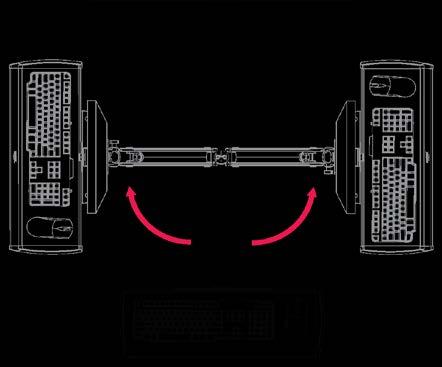
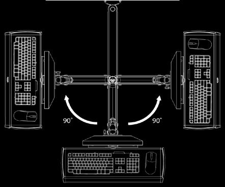
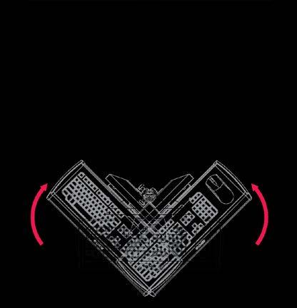
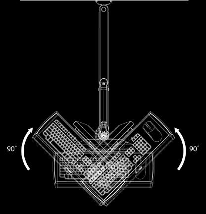
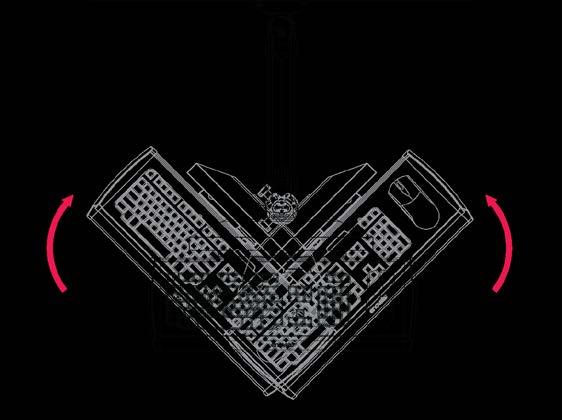
28 MOVEMENT ARM EXTENSION Both arms extended: 57" from wall One arm extended: 31" from wall No extension: 16 3/8" from wall KEYBOARD TILT MONITOR TILT* *Note: To maintain monitor tilt action, the weight of the mounted monitor must not exceed 12 lbs. Monitors weighing between 12 lbs. and 20 lbs. (maximum weight) must be mounted in a fixed position with no tilt option. 28


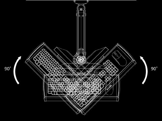
29 RANGE OF MOVEMENT (WITH EXTENSION ARM) 29


30 RANGE OF MOVEMENT (NO EXTENSION ARM) 30
31 PARTS LIST PARTS ORDERING: Contact Enovate Medical Technical Services department at (615) , ext. 1 or (888) , ext. 1. Description Part Number Adhesive Mouse Pad AM Cable Loom P Cable Tie Adhesive Pad WS CPU Brackets Small CPU Bracket AM Small Locking CPU Enclosure Box HC Large Locking CPU Enclosure Box HC Dual Lock Pads P edesk AM Extension Arm AM Extension Arm Cable Cover AM Heyco Shorty Plug AM Keyboard Tray, Standard AM Monitor Pole Assembly AM Monitor Pole Cable Cover AM Mouse Holder, Standard Tray HC Nut, 3/4-10 Nylock Jam Pivot Mount AM N light duty AM Riser Arm 850N medium duty AM N heavy duty AM Riser Arm Cable Cover AM Screws Button Head Screw, x 1/2" BHSC x.500 x.500 SS CPU Bracket Thumb Screw AM Cross Drive Metal Screw, 1/4" 20 x 2 1/2" CR-PHMS 1/4-20 x 2.5 x 2.5 ZNC Hex Head Self Tapping Metal Screw, 1/4"-14 x 2 1/2" HX-WHDS x 2.50 ZNC Hex Head Wood Screw HX-WLAG.25 x 4.0 ZNC Large Slotted Pan Head Screw AM Pan Head Screw, M4 x 16mm CR-PHMS M4 x 0.7 x 16 ZNC SNAPTOGGLE WS Standoff, #10 x 1/4" HC " AM Wall Track 42" AM " AM " AM Wall Track Cable Cover 42" AM " AM Wall Track End Cap AM Washers Wide Flat Washer, 1/4" x 1" SWFW 1/4 x 1.00 TYPE A ZNC Phenolic Washer, 1/4" x 1" PH-WSH.25 x 1.0 Plastic Washer AM
32 PARTS INDEX Adhesive Mouse Pad... 6, 17 Button Head Screw...8, 11, 12, 13 Cable Cover... 6, 21 Cable Loom... 8, 21 Cable Tie Adhesive Pad... 8, 19 CPU Bracket, Small... 7, 22 Cross Drive Metal Screw... 8, 13 Dual Lock Pads... 8, 17 edesk... 5, 7, 15, 19, 26 Extension Arm... 7, 14, 16, 21, 29 Hex Head Self Tapping Metal Screw... 8, 11 Hex Head Wood Screw Keyboard Tray, Standard... 6, 15, 17, 18, 19, 20, 26 Large Slotted Pan Head Screw... 8, 16 Locking CPU Enclosure Box... 7 Monitor Pole Assembly... 6, 15, 17, 21, 24 Mouse Holder... 6, 27 Nylock Jam Nut... 8, 15 Pan Head Screw, M4 x 16mm... 8, 17 Phenolic Washer... 8, 11, 12 Pivot Mount...6, 14, 15, 16 Plastic Washer... 8, 15, 16 Riser Arm... 5, 6, 15, 21, 23, 25 SNAPTOGGLE... 8, 10, 13 Standoff... 8, 17 Thumb Screw... 7, 22 Wall Track... 6, 10, 11, 12, 13 Wall Track Cable Cover... 6, 10, 21 Wall Track End Cap...6, 11, 12, 13 Wide Flat Washer... 8, 11, Park Avenue Murfreesboro, TN p. (888) f. (615) IM Enovate Medical, Inc. 32
MANUAL e130. Wallstation
 MANUAL 07.29.13 e130 Wallstation The Enovate Medical e130 Wallstation was designed to set a new standard in quality. Enovate Medical s goal is to provide a wallstation that is ready for years of use,
Midmark Care Exchange 6282 Standard Duty Wall Mounted Workstation
 INSTALLATION MANUAL Midmark Care Exchange 6282 Standard Duty Wall Mounted Workstation Weight Capacity 5-20 lbs 1210180MD Rev. C TABLE OF CONTENTS Tools Required / Installation Warnings / Disclaimer / Safety
FOR WALL MOUNT WORKSTATION
 INSTALLATION MANUAL FOR WALL MOUNT WORKSTATION Weight Capacity 5-20 lbs. 1210180 Rev. C TABLE OF CONTENTS Tools Required / Installation Warnings / Disclaimer / Safety Warning / Adjustment Notification...3
INSTALLATION INSTRUCTIONS Small Flat Panel Height-Adjustable, Extended Pitch Swing Arm Wall Mount Model KWE-110
 INSTALLATION INSTRUCTIONS Small Flat Panel Height-Adjustable, Extended Pitch Swing Arm Wall Mount Model KWE-110 The KWE dual swing arm wall mount is designed to provide a broad range of viewing for Small
Installation Instruction
 Tools Needed for Assembly Stud finder (for wood stud wall) Pencil Mark Electric drill Wood Stud Wall Installation Step 1. Locate the Wood Studs Installation Instruction Drill bit (for wood stud wall) Masonry
TITAN2-EDGE Public Access Computer Station Dual Track
 TITAN2-EDGE Public Access Computer Station Dual Track TITAN2-EDGE Rev A 6/17 Model TITAN2-EDGE ASSEMBLY AND ADJUSTMENT TITAN2-EDGE PARTS AND TOOLS PLEASE REVIEW these instructions before beginning the
SAM. Model: STV-C65 LCD Mobile Visualized Stand Instruction Manual. Weight Capacity: 1251bs / 56.7kg Suits LCD Flat Panel Display: 42"-55" Page 20
 SAM Model: STV-C65 LCD Mobile Visualized Stand Instruction Manual Weight Capacity: 1251bs / 56.7kg Suits LCD Flat Panel Display: 42"-55" 20 Step 6 LCD Mobile Lift Stand Model: STV-C65 Cable management
OB1U INSTALLATION INSTRUCTIONS. Interactive Flat Panel Over White Board Mount
 INSTALLATION INSTRUCTIONS Interactive Flat Panel Over White Board Mount Spanish Product Description German Product Description Portuguese Product Description Italian Product Description Dutch Product Description
INSTALLATION INSTRUCTIONS Small Flat Panel Mounts Model: F-Series
 INSTALLATION INSTRUCTIONS Small Flat Panel Mounts Model: F-Series This Instruction Manual covers most of the F-Series wall and desk mounts, as well as selected F-Series pole mounts. NOTE: Some F-Series
LC200DS1 Double Stud Articulating Wall Mount for Flat Panel Screens up to 32" with up to 200mm x 200mm VESA Mounting Patterns
 Page 1 of 6 LC200DS1 Double Stud Articulating Wall Mount for Flat Panel Screens up to 32" with up to 200mm x 200mm VESA Mounting Patterns A multi-position dual articulating arm for flat screens up to 60
INSTALLATION INSTRUCTIONS HEAVY DUTY TILT WALL MOUNT Model: PPH-2000
 INSTALLATION INSTRUCTIONS HEAVY DUTY TILT WALL MOUNT Model: PPH-2000 Specifications: Accomodates Akira and Orion 84" displays without interface bracket; accomodates other large flat panel displays with
4 BAY Low Profile WALL MOUNT CABINET
 D1/347 SSEMLY INSTRUCTIONS 4 Y Low Profile WLL MOUNT CINET TIP HZRD WRNING! Cabinet must be affixed to wall. For use to prevent tipping in compliance with capacity of cabinet specified. Use with heavier
INSTALLATION INSTRUCTIONS Small Flat Panel FMA Pivot Arrays Models: FMA-220 and FMA-320
 INSTALLATION INSTRUCTIONS Small Flat Panel FMA Pivot Arrays The FMA-220 and FMA-320 pivot array allow both horizontal and vertical display pitch adjustment. The pitch adjustment range is 30 (15 up / 15
Installing flat panels on the MPL15 wall mount
 Installing flat panels on the MPL15 wall mount The MPL15 (DS-VW775) is a full-service video wall mount that can accommodate tiled LCD panels with up to a 400 x 400 mm VESA pattern in portrait and landscape
MM540 Installation Instructions IMPORTANT SAFETY INSTRUCTIONS - SAVE THESE INSTRUCTIONS
 MM50 Installation Instructions IMPORTANT SAFETY INSTRUCTIONS - SAVE THESE INSTRUCTIONS Please read this entire manual before you begin. Do not unpack any contents until you verify all requirements on PAGE.
Small Flat Panel Height-Adjustable Dual Swing Arm Wall Mount With Universal Slat Wall Mount (MSP-JS-KWG-110)
") INSTALLATION INSTRUCTIONS Small Flat Panel Height-Adjustable Dual Swing Arm Wall Mount With Universal Slat Wall Mount () The dual swing arm desk mount is a sleek design providing a broad range of viewing
INSTALLATION INSTRUCTIONS Small Flat Panel Height-Adjustable Dual Swing Arm Wall Mount With Universal Slat Wall Mount () The dual swing arm desk mount is a sleek design providing a broad range of viewing
LARGE FLAT PANEL DISPLAY STATIC MOUNT PST 2000 Series
 INSTALLATION INSTRUCTIONS LARGE FLAT PANEL DISPLAY STATIC MOUNT The PST static wall mount accommodates large flat screens weighing up to 200 lbs (90.72kg). The teardrop holes in the mount allow for quick
Installation and Assembly - Universal Articulating Swivel Double-Arm for 42" - 60" Plasma Screens
 Installation and Assembly - Universal Articulating Swivel Double-Arm for 42" - 60" Plasma Screens Models: PLAV 70-UNL, PLAV 70-UNL-S PLAV 70-UNLP, PLAV 70-UNLP-S R This product is UL Listed. It must be
4 BAY Low Profile-Dual Displays WALL MOUNT CABINET
 D1/347M2 SSEMLY INSTRUTIONS 4 Y Low Profile-Dual Displays WLL MOUNT INET TIP HZRD WRNING! abinet must be affixed to wall. For use with video monitors weighing 175lbs (80kg) or less. Use with heavier televisions
Model MSPPWRTW Large Flat Panel Single Arm Wall Mount
 INSTALLATION INSTRUCTIONS Model Large Flat Panel Single Arm Wall Mount The is wall-mounted, rugged, versatile, and installer-friendly. The mount is compatible with the standard (14 x 14 ) PSB interface
INSTALLATION GUIDE. Model:B60 RECESSED IN WALL MOUNT
 INSTALLATION GUIDE Model:B60 RECESSED IN WALL MOUNT Features: Installs between 16 (406mm) wood stud centers Mounting Pattern Compliance: VESA 100*100mm up to 600 x 400mm Level 5 degree horizontal adjustment
INSTALLATION MANUAL PBL-UMP
 INSTALLATION MANUAL PBL-UMP Table of Contents Warning Statements... 4 Parts List... 5 Installation Tools... 5 Features... 7 Projector Preparation... 8 Bracket Installation... 10 Leveling the Mounting Bracket...
Medium Flat Panel Dual Swing Arm Wall Mount JWD-V
 INSTALLATION Medium Flat Panel Dual Swing Arm Wall Mount The single swing arm wall mount is designed for mounting a medium sized flat panel display. The can swing out from, or fold against, the wall depending
Installation and Assembly: In-wall Mount for 32" to 71" Flat Panel Screens
 Installation and Assembly: In-wall Mount for 32" to 71" Flat Panel Screens Model# IM760P, IM760P-S IM760PU, IM760PU-S Screen size range 32" to 71" (81 to 180 cm) 32" to 60" (81 to 152 cm) IM760P IM760P-S
LC200DS2 Double Stud Dual Articulating Wall Mount for Flat Panel Screens up to 32" with up to 200mm x 200mm VESA Mounting Patterns
 LC200DS2 Double Stud Dual Articulating Wall Mount for Flat Panel Screens up to 32" with up to 200mm x 200mm VESA Mounting Patterns Multi-position triple pivoting arms allows you to position the monitor
4 BAY Low Profile - SINGLE XL DISPLAY WALL MOUNT CABINET
 D1/347Mxl SSEMLY INSTRUCTIONS 4 Y Low Profile - SINGLE XL DISPLY WLL MOUNT CINET TIP HZRD WRNING! Cabinet must be affixed to wall. For use with video monitors weighing 300 lbs (136kg) or less. Use with
Flat Panel Dual Swing Arm Wall Mount (FWD-110) MSP-SA
 MSP-SA") INSTALLATION INSTRUCTIONS Flat Panel Dual Swing Arm Wall Mount (FWD-110) The dual arm wall mount was designed to support flat panel displays with 10 to 30 diagonal screens and weighing a maximum of 40
INSTALLATION INSTRUCTIONS Flat Panel Dual Swing Arm Wall Mount (FWD-110) The dual arm wall mount was designed to support flat panel displays with 10 to 30 diagonal screens and weighing a maximum of 40
SB-WM-ART1-M-BL. Weatherproof Universal Single-Arm Articulating Mount for Medium Displays INSTALLATION MANUAL
 SB-WM-ART1-M-BL Weatherproof Universal Single-Arm Articulating Mount for Medium Displays INSTALLATION MANUAL WARNING The maximum weight of this wall mount is 90 lbs (41 kg). Use with heavier than the maximum
INSTALLATION INSTRUCTIONS SMALL FLAT PANEL ADJUSTABLE PITCH WALL MOUNT Model: FTR Series
 INSTALLATION INSTRUCTIONS SMALL FLAT PANEL ADJUSTABLE PITCH WALL MOUNT Model: FTR Series Specifications: Designed for installation on single wood studs or drywall (1/2" minimum thickness); either option
19 to 39 TV WALL MOUNT - FULL MOTION
 19 to 39 TV WALL MOUNT - FULL MOTION RF-HTVMMAB For wood-stud and concrete wall installations Safety information and specifications...2 Tools needed...2 Package contents...3 Installation instructions...5
INSTALLATION INSTRUCTIONS SMALL FLAT PANEL ADJUSTABLE PITCH WALL MOUNT Model: FTR Series
 INSTALLATION INSTRUCTIONS SMALL FLAT PANEL ADJUSTABLE PITCH WALL MOUNT Model: FTR Series Specifications: Designed for installation on single wood studs or drywall (1/2" minimum thickness); either option
Articulating TV/Monitor Wall Mount Model: WA300S (Butterfly Series)
") P Articulating TV/Monitor Wall Mount Model: WA300S (Butterfly Series) Instruction Manual Images may different from actual product Disclaimer It is Dyconn s intention to have all the correct information
P Articulating TV/Monitor Wall Mount Model: WA300S (Butterfly Series) Instruction Manual Images may different from actual product Disclaimer It is Dyconn s intention to have all the correct information
Fixed Wall Arm. Installation Guide. Part number Rev E 2012 PolyVision Corporation All rights reserved
 Fixed Wall Arm Installation Guide Part number 2002003-001 Rev E 2012 PolyVision Corporation All rights reserved Table of contents Important Safety Instructions... 3 Overview... 4 Important considerations...
MM340 Installation Instructions IMPORTANT SAFETY INSTRUCTIONS - SAVE THESE INSTRUCTIONS
 MM30 Installation Instructions IMPORTANT SAFETY INSTRUCTIONS - SAVE THESE INSTRUCTIONS Please read this entire manual before you begin. Do not unpack any contents until you verify all requirements on PAGE.
PART #MSP-DCCST Flat Panel Tilt Mount
 INSTALLATION INSTRUCTIONS PART # Flat Panel Tilt Mount The Flat Panel Tilt Mount is a quick disconnect mounting solution for flat panel displays. The mount features adjustability between 0 and 15 degrees
INSTALLATION INSTRUCTIONS. Large Flat Panel Wall Mount Model: PRO-2000 Series
 INSTALLATION INSTRUCTIONS Large Flat Panel Wall Mount Model: PRO-2000 Series PRO-2000 Series Wall Mount Features: Accommodates large flat screens weighing up to 200 lbs (90.7 kg). Mounting brackets adapt
Yes 20 Charging Wall Cabinet for Tablets
 Built with Anthro-DNA Owner's Manual for Yes 20 Charging Wall Cabinet for Tablets Part # YESCABGMPW Components at a Glance 1 2 4 5 8 7 10 3 6 9 Front of Cabinet (closed) 1. Locking front door to User area.
Installation and Assembly - Universal Articulating Swivel Double-Arm for 42" - 60" Plasma Screens
 Installation and Assembly - Universal Articulating Swivel Double-Arm for 42" - 60" Plasma Screens Models: PLAV 70-UNL, PLAV 70-UNL-S PLAV 70-UNLP, PLAV 70-UNLP-S R This product is UL Listed. It must be
MM750 Installation Instructions
 MM750 Installation Instructions IMPORTANT SAFETY INSTRUCTIONS - SAVE THESE INSTRUCTIONS Please read this entire manual before you begin. Do not unpack any contents until you verify all requirements on
INSTALLATION INSTRUCTIONS Flat Panel Static Wall Mount Model: GSM-111
 INSTALLATION INSTRUCTIONS Flat Panel Static Wall Mount Model: GSM-111 The GSM-111 static wall mount fits most 23" to 30" displays. The GSM-111 is designed to adapt to VESA 200mm/ 100mm compliant displays.
INSTALLATION MANUAL PBC-UMS
 INSTALLATION MANUAL. PBC-UMS Premier Mounts 3130 E. Miraloma Avenue Anaheim, CA 92806 Phone: (800) 368-9700 Fax: (800) 832-4888 mounts@mounts.com www.mounts.com Rev. 01 PBL-110 Projector Mount Page 2 Installation
Tilting & Swiveling Plasma/LCD Flat Panel Wall Mount Installation Guide Model: A380SM
 Tilting & Swiveling Plasma/LCD Flat Panel Wall Mount Installation Guide Model: A380SM Easy installation Built-in level for easy positioning Corrective leveling adjustments after installation Forward /
DX-TVMLPTB03. Low-Profile TV Wall Mount ASSEMBLY GUIDE. For either wood-stud or concrete wall installations
 ASSEMBLY GUIDE DX-TVMLPTB03 Low-Profile TV Wall Mount For either wood-stud or concrete wall installations Safety information and specifications...2 Tools needed...........................3 Package contents......................3
Flat Panel Tilt Wall Mount (GPM-111)
") INSTALLATION INSTRUCTIONS Flat Panel Tilt Wall Mount () The tilt wall mount fits most 23 to 30 displays. The is designed to adapt to VESA 200mm/100mm compliant displays. This mount will also adapt to standard
INSTALLATION INSTRUCTIONS Flat Panel Tilt Wall Mount () The tilt wall mount fits most 23 to 30 displays. The is designed to adapt to VESA 200mm/100mm compliant displays. This mount will also adapt to standard
Installation and Assembly: Flat Video Wall Mount For 40" to 65" Flat Panel Displays
 Installation and Assembly: Flat Video Wall Mount For 40" to 65" Flat Panel Displays Model: DS-VW665 Maximum Load Capacity: 125 lb (57 kg) 1 of 11 ISSUED: 03-22-12 SHEET #: 125-9288-4 06-25-13 NOTE: Read
NW2F8-12. Fixed Wall Racks INSTALLATION INSTRUCTIONS
 INSTALLATION INSTRUCTIONS Fixed Wall Racks Spanish Product Description German Product Description Portuguese Product Description Italian Product Description Dutch Product Description French Product Description
Powered by. For further installation assistance: prxperformance.com/pages/murphy-rack
 Powered by The 90 Fold-in Murphy Rack is made by the creators of the original Profile Folding Rack at PRx Performance and is Patent Pending. An up-to-date record of patents and patent pending items can
QLF215 INSTRUCTION MANUAL
 QLF215 INSTRUCTION MANUAL We ll Make It Stress-Free If you have any questions along the way, just give us a call. 1-800-359-5520. We re ready to help! 1 2 3 IMPORTANT SAFETY INSTRUCTIONS SAVE THESE INSTRUCTIONS
ASSEMBLY INSTRUCTIONS. enook Pro
 ASSEMBLY INSTRUCTIONS enook Pro Product enook Pro for Monitors, 36w Part# EPM3616zz/xx Anthro Corporation 10450 SW Manhasset Dr. Tualatin, OR 97062 Toll-free: 800.325.3841 Fax: 800.325.0045 email: sales@anthro.com
MantelMount. TM1A Installation Instructions IMPORTANT SAFETY INSTRUCTIONS - SAVE THESE INSTRUCTIONS
 MantelMount TMA Installation Instructions IMPORTANT SAFETY INSTRUCTIONS - SAVE THESE INSTRUCTIONS TM Thank you for choosing the MantelMount television wall mount. Please read this entire manual before
MEDIUM FLAT PANEL DISPLAY TILT MOUNT MSP-MT (MTR-V)
") INSTALLATION INSTRUCTIONS MEDIUM FLAT PANEL DISPLAY TILT MOUNT (MTR-V) The tilt mount accommodates medium flat panel displays weighing up to 100 lbs (45.36kgs). The teardrop holes in the mount allow for
INSTALLATION INSTRUCTIONS MEDIUM FLAT PANEL DISPLAY TILT MOUNT (MTR-V) The tilt mount accommodates medium flat panel displays weighing up to 100 lbs (45.36kgs). The teardrop holes in the mount allow for
ASSEMBLY AND ADJUSTMENT
 EPPA MONITOR ARM EPPA Rev A 10/17 Model EPPA-XXX ASSEMBLY AND ADJUSTMENT EPPA MONITOR ARM PARTS AND TOOLS PLEASE REVIEW these instructions before beginning the assembly and adjustment procedures. Check
INSTALLATION INSTRUCTIONS
 INSTALLATION INSTRUCTIONS Universal Low Profile Tilt Mount Model: U.S. Toll Free: 1-866-752-6271 Outside N. America: 1-503-748-5799 E-mail: ts@planar.com FRANCE Phone: +33 5 6378 3810 E-mail: emeats@planar.com
Elo Touch Solutions Wallmounting Kit for the 7001L IDS Touchmonitors
 Installation Manual Elo Touch Solutions Wallmounting Kit for the 7001L IDS Touchmonitors SW602083 Rev E Table of Contents Chapter 1: Safety Warning... 3 Chapter 2: Kit Contents... 4 Included in Kit...
INSTALLATION INSTRUCTIONS
 INSTALLATION INSTRUCTIONS Universal Low Profile Flat Mount Model: U.S. Toll Free: 1-866-752-6271 Outside N. America: 1-503-748-5799 E-mail: ts@planar.com FRANCE Phone: +33 5 6378 3810 E-mail: emeats@planar.com
SB-WM-ART2-L-BL SB-WM-ART2-XL-BL
 SB-WM-ART2-L-BL SB-WM-ART2-XL-BL Weatherproof Universal Dual-Arm Articulating Mount for Large TVs INSTALLATION MANUAL WARNING The maximum weight of this wall mount is 150 lbs (68.04 kg). Use with heavier
INSTALLATION INSTRUCTIONS
 INSTALLATION INSTRUCTIONS PARTS REQUIRED Single QuickStand Lite Parts A (1) Lower Arm A B C D B (1) Upper Arm C (1) Base D (1) Base Plate E (1) M8 Dynamic Arm Long F (1) Clamp Bracket G H (1) VESA Plate
MPA-9000 Universal Ceiling Projector Mount Kit
 I N S T R U C T I O N M A N U A L Universal Ceiling Projector Mount Kit The Universal Ceiling Projector Mount provides a unique, simplified method of ceiling mounting your inverted projector. This low
INSTALL INSTRUCTIONS WELCOME TO THE NEWAGE PERFORMANCE CABINETRY SERIES NEWAGE STEEL WELDED CABINETRY
 NEWAGE STEEL WELDED CABINETRY WELCOME TO THE NEWAGE PERFORMANCE CABINETRY SERIES ALL CABINETS MUST BE MOUNTED TO STUDS ON A SECURE WALL, AS PER THESE INSTRUCTIONS. FAILURE TO DO SO MAY RESULT IN SERIOUS
Installation and Assembly: Full Service Video Wall Mount
 Installation and Assembly: Full Service Video Wall Mount Model: DS-VW765-LAND Max UL Load Capacity: 125 lb (57 kg) 1 of 12 ISSUED: 05-13-11 SHEET #: 145-9011-5 05-21-12 Note: Read entire instruction sheet
PFW 6851 Display Wall Mount, Turn & Tilt 80 kg INSTALLATION INSTRUCTIONS
 Display Wall Mount, Turn & Tilt 80 kg INSTALLATION INSTRUCTIONS 9531-007-Z00-01 Table of Contents Warning Statements 2 Parts List 3 Installation Tools 3 Wood Stud Installation 5 Concrete Surface Installation
Video Wall Installation Instructions 2W X 3H, 3W X 3H
 Video Wall Installation Instructions 2W X 3H, 3W X 3H www.microndisplaysolutions.com Table of Contents Important Safety Instructions... 3 Configuration... 4 Package Contents, included and optional items...
Dual Arm Tilt LCD Mount
 Installation Manual model # 51324 M o u n t i n g S y s t e m s Dual Arm Tilt LCD Mount Fits Displays 13 to 32 Supports Up to 50 lbs (23 kgs) Projection from Wall from 3 to 17 Meets VESA Standards 50/75/100,
QLF214 INSTRUCTION MANUAL
 QLF214 INSTRUCTION MANUAL We ll Make It Stress-Free If you have any questions along the way, just give us a call. 1-800-359-5520. (UK: 0800 056 2853) We re ready to help! CAUTION: IMPORTANT SAFETY INSTRUCTIONS
6 BAY AV CREDENZA WITH DUAL DISPLAY MOUNT
 D2/367M2 SSEMLY INSTRUCTIONS 6 Y V CREDENZ WITH DUL DISPLY MOUNT TIP HZRD WRNING! For use with video monitors weighing 175lbs (80kg) or less. Use with heavier televisions may result in instability causing
INSTRUCTION BOOKLET #C20
 INSTRUCTION BOOKLET #C0 WARNING! ALL MURPHY/WALLBED SYSTEMS CONTAIN STORED ENERGY. FAILURE TO USE AND FOLLOW THESE INSTRUCTIONS DURING THE INSTALLATION PROCESS COULD RESULT IN SEVERE PERSONAL INJURY TO
INSTALLATION INSTRUCTIONS
 INSTALLATION INSTRUCTIONS SPORTSMAN WINCH MOUNT GRILLE GUARD APPLICATION: 2016-2018 Toyota Tacoma PART NUMBER: 40-93885, 45-93880, 46-23885 ITEM QUANTITY DESCRIPTION TOOLS NEEDED 1 1 WINCH TRAY 15MM SOCKET
INSTRUCTION BOOKLET #C21. For Wallbed models: KING SIZE
 For Wallbed models: KING SIZE INSTRUCTION BOOKLET #C1 WARNING! ALL MURPHY/WALLBED SYSTEMS CONTAIN STORED ENERGY. FAILURE TO USE AND FOLLOW THESE INSTRUCTIONS DURING THE INSTALLATION PROCESS COULD RESULT
QLF214 INSTRUCTION MANUAL
 QLF214 INSTRUCTION MANUAL We ll Make It Stress-Free If you have any questions along the way, just give us a call. 1-800-359-5520 We re ready to help! Scan for easy install video san.us/1145 CAUTION: IMPORTANT
FSM / FULL SWING WALL MOUNT. For Flat Panel Screens. User Manual
 FSM- 3760 / FULL SWING WALL MOUNT For 37-60 Flat Panel Screens User Manual Thank you for choosing Gabor. Thank you for choosing Gabor s full swing flat panel screen wall mount. This heavy-duty wall mount
INSTALLATION INSTRUCTIONS Medium Flat Panel Model MSP-SI1
 INSTALLATION INSTRUCTIONS Medium Flat Panel Model MSP-SI1 IMPORTANT! : The MSP-S11 Mount is designed for use with Sharp 45" LCD displays that have a 200mm x 200mm mounting pattern. IMPORTANT! : The mount
Hatch Whiteboard: Portable Stand Installation Instructions
 Hatch Whiteboard: Portable Stand Installation Instructions Remove Projector Wall Plate 1. Open the wall mount for the projector. 2. Remove the shipping screw from the front center of the mount arm. 1 P
3 BAY AV CREDENZA WITH SINGLE DISPLAY MOUNT
 D2/337M1 SSEMLY INSTRUCTIONS 3 Y V CREDENZ WITH SINGLE DISPLY MOUNT TIP HZRD WRNING! For use with video monitors weighing 175lbs (80kg) or less. Use with heavier televisions may result in instability causing
EPPA2-KIT DUAL MONITOR ARM CONVERSION
 EPPA2-KIT DUAL MONITOR ARM CONVERSION EPPA2-KIT Rev A 10/17 Model EPPA2-KIT-XXX ASSEMBLY AND ADJUSTMENT EPPA2-KIT PARTS AND TOOLS PLEASE REVIEW these instructions before beginning the assembly and adjustment
 Menu Board Tilt or Fixed Mount Installation Instructions MDS1T-200, MDS1T-300, MDS1T-400 MDS2T-200, MDS2T-300, MDS2T-400 MDS3T-200, MDS3T-300, MDS3T-400 MDS4T-200, MDS4T-300, MDS4T-400 MDS5T-200, MDS5T-300,
ēno one Adjustable Wall Mount and Adjustable Mobile Stand Installation Guide
 Installation Guide Part number 2002105-001 Rev B 2011 PolyVision Corporation All rights reserved Table of contents Overview... 3 Important considerations... 3 Adjustable Wall Mount considerations... 3
LCD MONITOR/TV WALL MOUNT
 INSTALLATION INSTRUCTIONS LCD MONITOR/TV WALL MOUNT DUAL DESK CLAMP (RFCD-110) S CAUTION CAUTION A alerts you to the possibility of serious injury or death if you do not follow the instructions. A CAUTION
INSTRUCTION BOOKLET #34. For Wallbed models: KING SIZE SIERRA WITH STORAGE HEADBOARD
 For Wallbed models: KING SIZE SIERRA WITH STORAGE HEADBOARD INSTRUCTION BOOKLET #34 WARNING! ALL MURPHY/WALLBED SYSTEMS CONTAIN STORED ENERGY. FAILURE TO USE AND FOLLOW THESE INSTRUCTIONS DURING THE INSTALLATION
PHTM200 - Phantom 200 Flat Screen Wall Mount with Wafer Thin Projection Fits Screens up to 50 lbs with 200mm Mounting Patterns
 PHTM200 - Phantom 200 Flat Screen Wall Mount with Wafer Thin Projection Fits Screens up to 50 lbs with 200mm Mounting Patterns Features: Durable high quality gloss black baked on powder coat finish Fits
Installation and Assembly: In-wall Mount for 32" to 71" Flat Panel Displays
 Installation and Assembly: In-wall Mount for 32" to 71" Flat Panel Displays Model# Display size range IM760P, IM760P-S 32" to 71" (81 to 180 cm) IM760PU, IM760PU-S 32" to 65" (81 to 165 cm) This product
IMPORTANT WARNINGS AND CAUTIONS!
 I N S T R U C T I O N M A N U A L The Christie Vivid Green ceiling mount will suspend your Christie Vivid Green projector in an upright position to compliment conference rooms, classrooms or home theater
Barn Door & Hardware Installation Guide
 Barn Door & Hardware Guide INTRODUCTION Thank you for purchasing our hardware. Our barn door and hardware will add a stunning accent to your living environment and maximize its space. This manual covers
Assembly Instructions for model: VMPR1
 Assembly Instructions for model: VMPR1 Congratulations on your purchase! The VMPR1 ceiling mount provides a unique, simplified method of ceiling mounting inverted LCD/DLP projectors. Its low profile design
Model : TLX-350FM. TV Mount Installation Guide
 Model : TLX-350FM TV Mount Installation Guide Thank you for choosing Stanley the hardware of choice for Architects, Contractors, and Home Owners for its quality, performance and dependability. Following
Linear Hook- on Worksurfaces
 Linear Hook- on Worksurfaces Linear Hook-On Worksurfaces come in three depths and seven lengths. Different worksurfaces have different reqirements for installation that are outlined below. 27 inch deep
ASSEMBLY AND CARE INSTRUCTIONS JUST FOR KIDS 355
 ASSEMBLY AND CARE INSTRUCTIONS VERSION: 8920100 (Revised 06/16) JUST FOR KIDS 355 SALES AND SERVICE spiethamerica.com Canada and International 135 Forestview Road, PO Box 40 Orillia, Ontario, Canada L3V
Installing Brackets to Minimize Distortion in Your SMART Board 685ix Interactive Whiteboard System s Projected Image
 UX60-RFK-685 Installing Brackets to Minimize Distortion in Your SMART Board 685ix Interactive Whiteboard System s Projected Image Follow these instructions to install brackets on your SMART Board 685ix
Full Motion Gas Spring TV Wall Mount - 24" to 55" Installation Instructions
 Full Motion Gas Spring TV Wall Mount - 24" to 55" Installation Instructions 04-1102A Caution Prior to installation of this product, the installation instructions should be read and completely understood.
User and Installation Manual. For Tandem Arm and Slim Line Models. Tandem Arm. Slim Line
 Tandem Arm User and Installation Manual For Tandem Arm and Slim Line Models Tandem Arm Slim Line Table of Contents Warnings... 4 Box Contents... 5 Hardware Kits... 6 Parts... 7 Tandem Arm Installation...
ETX Powered Loudspeaker Accessories
 ETX Powered Loudspeaker Accessories ETX-BRKT10, ETX-BRKT12, ETX-BRKT15, ETX-TCA-S, ETX-TCA-L, and ETX-BRKT35 en Installation Guide en 3 Table of contents 1 Safety 4 2 Installation 6 2.1 Wall mount bracket
ASSEMBLY INSTRUCTIONS TALL CABINET - MODEL CS30
 ASSEMLY INSTRUCTIONS TALL CAINET - MOEL CS30 To avoid SERIOUS INJURY or AMAGE to personal belongings: O NOT overload the cabinet or the shelves, maximum weight limit for feet or caster installation is
SM-RAZOR-ART2-L / SM-RAZOR-ART2-XL
 SM-RAZOR-ART2-L / SM-RAZOR-ART2-XL Strong Razor Series Articulating Mount for Large and Extra Large Displays INSTRUCTION MANUAL Installation Manual Warnings: Installation of this product should be done
Installation Manual Flat Track Series
 Manual Flat Track Series Contents Safety...1 Parts...2 Hardware.......................................... 2 Tools Required..................................... 4.............................................
Equilibrium. Conference Table. Installation Instruction. Revision B 11/07/16
 Equilibrium Conference Table Installation Instruction Revision B 11/07/16 Equilibrium End User Agreement Enwork Equilibrium table bases must be installed directly onto a four inch minimum thickness concrete
F l a t S c r e e n A R M S I n s t a l l a t i o n
 ITEM NUMBERS (1) #TOACAORG16 (2) #TOACAORG20 (3) #TOACATRP24 (4) #TOACATRP30 (5) #TOACATRPDS (6) #TOACATRPSS TOOLS REQUIRED (1) 3/8 Wrench (not provided) (2) Phillips head screwdriver (not provided) (1)
Copyright Black Box Corporation. All rights reserved Park Drive Lawrence, PA Fax
 Copyright 2003. Black Box Corporation. All rights reserved. 1000 Park Drive Lawrence, PA 15055-1018 724-746-5500 Fax 724-746-0746 JULY 2003 RM3010A RM315-R2 RM323-R2 RM329 RM451 RM457 RM3020A RM316 RM324-R2
https://www.wallbedsbywilding.com/wallbed-installation-studio-series/
 For Wallbed models: KING SIZE INSTRUCTION BOOKLET #C1 Watch step by step installation instructions at: https://www.wallbedsbywilding.com/wallbed-installation-studio-series/ WARNING! ALL MURPHY/WALLBED
TIP FOR GETTING STARTED
 Tip for getting started TIP FOR GETTING STARTED Be careful not to drill into any electrical wires, ductwork, plumbing or other damagable components. If you have any questions on the locations of these
ATLANTIS RAIL Contact Information
 ATLANTIS RAIL Contact Information Customer Service (800) 541-6829 (508) 732-9191 Spectrum System Installation Instructions Atlantis Rail s Spectrum System is an easy to install, universal cable railing
SM-RAZOR-T-M/L/XL. Strong Low Profile Tilt Mount for Ultra-Thin Flat-Panel TVs INSTRUCTION MANUAL
 SM-RAZOR-T-M/L/XL Strong Low Profile Tilt Mount for Ultra-Thin Flat-Panel TVs INSTRUCTION MANUAL WARNINGS: Installation of this product should be done by a qualified professional. Do not begin installation