Autodesk Inventor Tips and Tricks. Carsten John Jacobsen
|
|
|
- Dustin Montgomery
- 5 years ago
- Views:
Transcription


1 Autodesk Inventor Tips and Tricks Carsten John Jacobsen
2 Tips and Tricks Summary If you are new to the Autodesk collection or you have been using the application for a decade you will learn something from this short quick paced presentation of tips and tricks We will outline tips and tricks in the Autodesk applications that are most familiar to you These tips and tricks will outline some of the less obvious commands or features that may be used in your daily design tasks
3 Inventor


4 Interface Autodesk Screen Cast Illustrate your point with screencast Capture video and mouse clicks Record, edit and share Share online with other users or keep private Download here, for FREE:
5

6 Interface Annotation Scale Application Options Tools>Application Options>General>Annotation scale Struggle to see annotation no more with this options Increase the value and watch your annotations scale up Including constraint glyphs
7

8 Interface New Window View Tab on Ribbon>Window Panel>New Have multiple windows of your model open at the same time This will not open another session of Inventor Activate the windows by using the open file tabs in the status bar
9


10 Interface Supplier Content In combination with Inventor Any CAD function Use supplier content directly in the application Inventor ribbon>collaborate>supplier Content Save and import from PARTSolutions, 3DModelSpace and TraceParts NOTE: try GrabCAD too!
11

12 Interface Mini Toolbar Turn on and off the mini toolbar The mini toolbar was introduced in earlier versions, with no on and off Inventor ribbon>view>user Interface>Mini Toolbar When on you will only use the mini toolbar all dialog boxes will be collapsed
13


14 Sketch Trim in extend and extend in trim As you use the trim or extend tool in the sketch environment hold shift Trim and extend in one command (as per ACAD) Hold Ctrl to specify the trim segment Left click and drag to get lasso
15


16 Sketch Create construction or centerlines lines during line creation When drawing lines in sketches Right click and choose construction or centerline All in one command No need to exit the line command to convert lines
17

18 Sketch Disable infer constraints temporarily Hold ctrl when sketch command is active This will disable infer constraints Allow to work with no constraints Release ctrl to work as normal
19


20 Sketch Extrude Interfering Sketches Problems selecting extruded profiles? Add sketch points to line intersections, this will allow a clear profile selection when extruding
21

22 Sketch Sketch dimensions to line not point Apply dimensions as intended Select lines for linear dimensions If points are selected, when the geometry is edited constraints can fall from the sketch and cause unconstrained sketches
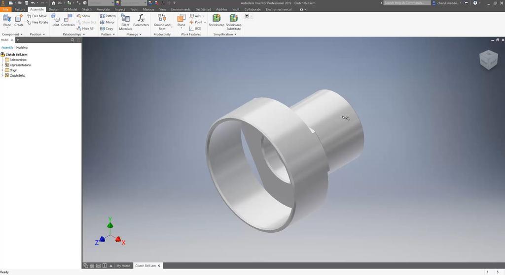
23

24 Part Sketch driven pattern Drive the location of a feature using sketch points Stop replicating the same feature and save time One sketch can drive the feature positions
25


26 Part Split Tool & Move Bodies When creating Multi-Body designs consider: Using the split tool to split one solid to two solids Then using the move bodies command create gaps Linear or rotation directions
27
28 Part Extend start hole creation When using the hole command tick the box for extend start This will extend the start face of the hole The new option removes the fragment that used to be left after certain holes where created
29


30 Assembly Perspective View in Assemblies Orthographic view is set as default Changing this view to perspective within and assembly allows: Zoom movement passes through parts/components Allowing visibility of internal parts/components
31

32 Assembly Move faces in Assembly Move faces command within the assembly environment: Move faces parametrically within assemblies Changes can be made to reflect future variations (concept)
33

34 Assembly Alt-Drag constrain Hold down Alt key on the keyboard Click and hold on a component in the graphics window near where constraint will be placed Drag to location Constraint is created NOTE: When there are options, use Space bar to cycle though constraint placement
35


36 Assembly Place and drag constraints Place parts and add constraints by: During placement of parts select faces, edges or points Then select the corresponding face, edge or point Constraints will be placed
37

38 Assembly Ground and root components Use ground and root component to move and ground a component to the assembly origin Choose from the new list: Ground at origin Create origin flush constraints Reposition to the top of the browser
39


40 Drawings Automated Centerlines After view creation right click and choose automated centerlines This will create centerlines selected by feature or pattern Save time applying each centerline individually
41

42 Drawings Hold Ctrl when creating sections When creating Section views Hold down the Ctrl key This will break alignment as you place the view
43

44 Drawings Copy drawing recources folder Right click the Drawing resources folder from the drawing browser Then select Copy In the new drawing, right click on the drawing resources folder and paste Any resources that exist in the new drawing with the same name can be replaced or created as new resources
45


46 Drawings Text Border Annotate tab>text panel>text or Leader Text Format Text dialog box Border Options dropdown list Detail view will move geometry if change is made NOTE: Text box grips can resize the border
47
48 Q & A
Introduction to Autodesk Inventor for F1 in Schools (Australian Version)
") Introduction to Autodesk Inventor for F1 in Schools (Australian Version) F1 in Schools race car In this course you will be introduced to Autodesk Inventor, which is the centerpiece of Autodesk s Digital
Introduction to Autodesk Inventor for F1 in Schools (Australian Version) F1 in Schools race car In this course you will be introduced to Autodesk Inventor, which is the centerpiece of Autodesk s Digital
ME Week 2 Project 2 Flange Manifold Part
 1 Project 2 - Flange Manifold Part 1.1 Instructions This project focuses on additional sketching methods and sketching commands. Revolve and Work features are also introduced. The part being modeled is
Appendix R5 6. Engineering Drafting. Broken View
 Updating Using Autodesk Inventor to Release 5 Appendix R5 6 Engineering Drafting Chapter 6 delineates the concepts of engineering drafting. You output orthographic views from solid parts and orthographic
Quick Start for Autodesk Inventor
 Quick Start for Autodesk Inventor Autodesk Inventor Professional is a 3D mechanical design tool with powerful solid modeling capabilities and an intuitive interface. In this lesson, you use a typical workflow
Toothbrush Holder. A drawing of the sheet metal part will also be created.
 Prerequisite Knowledge Previous knowledge of the following commands is required to complete this lesson; Sketch (Line, Centerline, Circle, Add Relations, Smart Dimension,), Extrude Boss/Base, and Edit
Module 2: Radial-Line Sheet-Metal 3D Modeling and 2D Pattern Development: Right Cone (Regular, Frustum, and Truncated)
") Inventor (5) Module 2: 2-1 Module 2: Radial-Line Sheet-Metal 3D Modeling and 2D Pattern Development: Right Cone (Regular, Frustum, and Truncated) In this tutorial, we will learn how to build a 3D model
Inventor (5) Module 2: 2-1 Module 2: Radial-Line Sheet-Metal 3D Modeling and 2D Pattern Development: Right Cone (Regular, Frustum, and Truncated) In this tutorial, we will learn how to build a 3D model
An Introduction to Autodesk Inventor 2011 and AutoCAD Randy H. Shih SDC PUBLICATIONS. Schroff Development Corporation
 An Introduction to Autodesk Inventor 2011 and AutoCAD 2011 Randy H. Shih SDC PUBLICATIONS www.sdcpublications.com Schroff Development Corporation An Introduction to Autodesk Inventor 2011 and AutoCAD 2011
Parametric Modeling. with. Autodesk Inventor Randy H. Shih. Oregon Institute of Technology SDC
 Parametric Modeling with Autodesk Inventor 2009 Randy H. Shih Oregon Institute of Technology SDC PUBLICATIONS Schroff Development Corporation www.schroff.com Better Textbooks. Lower Prices. iii Table of
Lesson 6 2D Sketch Panel Tools
 Lesson 6 2D Sketch Panel Tools Inventor s Sketch Tool Bar contains tools for creating the basic geometry to create features and parts. On the surface, the Geometry tools look fairly standard: line, circle,
Autodesk Inventor 2016
 Parametric Modeling with Autodesk Inventor 2016 Randy H. Shih SDC PUBLICATIONS Better Textbooks. Lower Prices. www.sdcpublications.com Powered by TCPDF (www.tcpdf.org) Visit the following websites to learn
Creo Parametric Primer
 PTC Creo Parametric - Primer Student and Academic Editions 02 Helpful hints are enclosed in red brackets or round bubbles like this one! Creo Parametric Primer THIS VERSION OF THE CREO PRIMER HAS BEEN
Up to Cruising Speed with Autodesk Inventor (Part 1)
") 11/29/2005-8:00 am - 11:30 am Room:Swan 1 (Swan) Walt Disney World Swan and Dolphin Resort Orlando, Florida Up to Cruising Speed with Autodesk Inventor (Part 1) Neil Munro - C-Cubed Technologies Ltd. and
11/29/2005-8:00 am - 11:30 am Room:Swan 1 (Swan) Walt Disney World Swan and Dolphin Resort Orlando, Florida Up to Cruising Speed with Autodesk Inventor (Part 1) Neil Munro - C-Cubed Technologies Ltd. and
Pull Down Menu View Toolbar Design Toolbar
 Pro/DESKTOP Interface The instructions in this tutorial refer to the Pro/DESKTOP interface and toolbars. The illustration below describes the main elements of the graphical interface and toolbars. Pull
Creo Parametric Primer
 Creo Parametric Primer Creo Parametric Primer Education Editions 2 C2-SE-L1-004-1.0 Written by Tim Brotherhood and Adam Haas Conditions of use Acknowledgements Feedback tbrotherhood@ptc.com Product code
Tools for Design. with VEX Robot Kit: Randy H. Shih Oregon Institute of Technology SDC PUBLICATIONS
 Tools for Design with VEX Robot Kit: AutoCAD 2011 and Autodesk Inventor 2011 2D Drawing 3D Modeling Hand Sketching Randy H. Shih Oregon Institute of Technology INSIDE: SUPPLEMENTAL FILES ON CD SDC PUBLICATIONS
Getting Started. Chapter. Objectives
 Chapter 1 Getting Started Autodesk Inventor has a context-sensitive user interface that provides you with the tools relevant to the tasks being performed. A comprehensive online help and tutorial system
8 Working Drawings in AutoCAD
 8 Working Drawings in AutoCAD Most engineering designs consist of more than a single part. Usually there are a several or many parts that must fit and work together. When we are creating the drawings of
Module 1E: Parallel-Line Flat Pattern Development of Sheet- Metal Folded Model Wrapping the 3D Space of An Oblique Circular Cylinder
 Inventor (10) Module 1E: 1E- 1 Module 1E: Parallel-Line Flat Pattern Development of Sheet- Metal Folded Model Wrapping the 3D Space of An Oblique Circular Cylinder In this Module, we will explore the topic
Revit Structure 2012 Basics:
 SUPPLEMENTAL FILES ON CD Revit Structure 2012 Basics: Framing and Documentation Elise Moss autodesk authorized publisher SDC PUBLICATIONS www.sdcpublications.com Schroff Development Corporation Structural
Learning. Autodesk Inventor 2019 SDC. Modeling, Assembly and Analysis. Randy H. Shih. Better Textbooks. Lower Prices.
 Learning Autodesk Inventor 2019 Modeling, Assembly and Analysis Randy H. Shih SDC PUBLICATIONS Better Textbooks. Lower Prices. www.sdcpublications.com Powered by TCPDF (www.tcpdf.org) Visit the following
Estimated Time Required to Complete: 45 minutes
 Estimated Time Required to Complete: 45 minutes This is the first in a series of incremental skill building exercises which explore sheet metal punch ifeatures. Subsequent exercises will address: placing
Creo Parametric Primer
 Creo Parametric Primer Creo Parametric Primer Education Editions C1-SE-L1-004-1.0 Written by Tim Brotherhood and Adam Haas Conditions of use Acknowledgements Feedback tbrotherhood@ptc.com Product code
Module 1G: Creating a Circle-Based Cylindrical Sheet-metal Lateral Piece with an Overlaying Lateral Edge Seam And Dove-Tail Seams on the Top Edge
 Inventor (10) Module 1G: 1G- 1 Module 1G: Creating a Circle-Based Cylindrical Sheet-metal Lateral Piece with an Overlaying Lateral Edge Seam And Dove-Tail Seams on the Top Edge In Module 1A, we have explored
Chapter 1. Creating, Profiling, Constraining, and Dimensioning the Basic Sketch. Learning Objectives. Commands Covered
 Chapter 1 Creating, Profiling, Constraining, and Dimensioning the Basic Sketch Learning Objectives After completing this chapter, you will be able to: Draw the basic outline (sketch) of designer model.
Modeling an Airframe Tutorial
 EAA SOLIDWORKS University p 1/11 Difficulty: Intermediate Time: 1 hour As an Intermediate Tutorial, it is assumed that you have completed the Quick Start Tutorial and know how to sketch in 2D and 3D. If
Drawing a Plan of a Paper Airplane. Open a Plan of a Paper Airplane
 Inventor 2014 Paper Airplane Drawing a Plan of a Paper Airplane In this activity, you ll create a 2D layout of a paper airplane. Please follow these directions carefully. When you have a question, reread
Lesson 4 Holes and Rounds
 Lesson 4 Holes and Rounds 111 Figure 4.1 Breaker OBJECTIVES Sketch arcs in sections Create a straight hole through a part Complete a Sketched hole Understand the Hole Tool Use Info to extract information
SolidWorks Part I - Basic Tools SDC. Includes. Parts, Assemblies and Drawings. Paul Tran CSWE, CSWI
 SolidWorks 2015 Part I - Basic Tools Includes CSWA Preparation Material Parts, Assemblies and Drawings Paul Tran CSWE, CSWI SDC PUBLICATIONS Better Textbooks. Lower Prices. www.sdcpublications.com Powered
2809 CAD TRAINING: Part 1 Sketching and Making 3D Parts. Contents
 Contents Getting Started... 2 Lesson 1:... 3 Lesson 2:... 13 Lesson 3:... 19 Lesson 4:... 23 Lesson 5:... 25 Final Project:... 28 Getting Started Get Autodesk Inventor Go to http://students.autodesk.com/
Inventor 2016 Essentials Plus
 Autodesk NEW Features a chapter on sheet metal design Inventor 2016 Essentials Plus Daniel T. Banach & Travis Jones SDC PUBLICATIONS Better Textbooks. Lower Prices. www.sdcpublications.com Powered by TCPDF
User Guide V10 SP1 Addendum
 Alibre Design User Guide V10 SP1 Addendum Copyrights Information in this document is subject to change without notice. The software described in this document is furnished under a license agreement or
Alternatively, the solid section can be made with open line sketch and adding thickness by Thicken Sketch.
 Sketcher All feature creation begins with two-dimensional drawing in the sketcher and then adding the third dimension in some way. The sketcher has many menus to help create various types of sketches.
Ball Valve Assembly. On completion of the assembly, we will create the exploded view as shown on the right.
 Ball Valve Assembly Supplied are the main components of a ball valve. In this exercise you will assemble the valve as shown below Left. (N.B. Socket head cap screws are not supplied these will be created
Diane Burton, STEM Outreach.
 123D Design Tutorial: LED decoration Before using these instructions, it is very helpful to watch this video screencast of the CAD drawing actually being done in the software. Click this link for the video
Drawing and Assembling
 Youth Explore Trades Skills Description In this activity the six sides of a die will be drawn and then assembled together. The intent is to understand how constraints are used to lock individual parts
Engineering Technology
 Engineering Technology Introduction to Parametric Modelling Engineering Technology 1 See Saw Exercise Part 1 Base Commands used New Part This lesson includes Sketching, Extruded Boss/Base, Hole Wizard,
Assemble This! [Part 1]
![Assemble This! [Part 1]](/thumbs/74/69963588.jpg "Assemble This! [Part 1]") 11/30/2006-3:00 pm - 4:30 pm Room:Marcello - 4401 (MSD Campus) Assemble This! [Part 1] Alan Kalameja - Trident Technical College and Kevin Robinson (Assistant); Patrik Chartrand (Assistant) MA34-1L This
11/30/2006-3:00 pm - 4:30 pm Room:Marcello - 4401 (MSD Campus) Assemble This! [Part 1] Alan Kalameja - Trident Technical College and Kevin Robinson (Assistant); Patrik Chartrand (Assistant) MA34-1L This
When you complete this assignment you will:
 Objectives When you complete this assignment you will: 1. sketch and create models using basic commands. 2. create a multi-part model using the assembly drawings. 3. sketch and dimension problems. 3. extrude
Las Vegas, Nevada, December 3 6, Speaker Name: Alan Kalameja. Course Title: Autodesk Inventor Assembly Modeling.
 Las Vegas, Nevada, December 3 6, 2002 Speaker Name: Alan Kalameja Course Title: Autodesk Inventor Assembly Modeling Course ID: MA31-1 Course Outline: This class is designed to take an individual through
A Quick Spin on Autodesk Revit Building
 11/28/2005-3:00 pm - 4:30 pm Room:Americas Seminar [Lab] (Dolphin) Walt Disney World Swan and Dolphin Resort Orlando, Florida A Quick Spin on Autodesk Revit Building Amy Fietkau - Autodesk and John Jansen;
Module 1H: Creating an Ellipse-Based Cylindrical Sheet-metal Lateral Piece
 Inventor (10) Module 1H: 1H- 1 Module 1H: Creating an Ellipse-Based Cylindrical Sheet-metal Lateral Piece In this Module, we will learn how to create an ellipse-based cylindrical sheetmetal lateral piece
AEROPLANE. Create a New Folder in your chosen location called Aeroplane. The four parts that make up the project will be saved here.
 AEROPLANE Prerequisite Knowledge Previous knowledge of the following commands is required to complete this lesson. Sketching (Line, Rectangle, Arc, Add Relations, Dimensioning), Extrude, Assemblies and
Revit Structure 2014 Basics
 Revit Structure 2014 Basics Framing and Documentation Elise Moss Authorized Author SDC P U B L I C AT I O N S Better Textbooks. Lower Prices. www.sdcpublications.com Powered by TCPDF (www.tcpdf.org) Visit
Parametric Design 1
 Western Technical College 10606115 Parametric Design 1 Course Outcome Summary Course Information Description Career Cluster Instructional Level Total Credits 3 This course is designed to introduce students
Module 1C: Adding Dovetail Seams to Curved Edges on A Flat Sheet-Metal Piece
 1 Module 1C: Adding Dovetail Seams to Curved Edges on A Flat Sheet-Metal Piece In this Module, we will explore the method of adding dovetail seams to curved edges such as the circumferential edge of a
Creo Parametric 4.0 Basic Design
 Creo Parametric 4.0 Basic Design Contents Table of Contents Introduction...1 Objective of This Textbook...1 Textbook Outline...2 Textbook Conventions...3 Exercise Files...3 System Configuration...4 Notes
Lesson 4 Extrusions OBJECTIVES. Extrusions
 Lesson 4 Extrusions Figure 4.1 Clamp OBJECTIVES Create a feature using an Extruded protrusion Understand Setup and Environment settings Define and set a Material type Create and use Datum features Sketch
Autodesk Inventor. In Engineering Design & Drafting. By Edward Locke
 Autodesk Inventor In Engineering Design & Drafting By Edward Locke Engineering Design Drafting Essentials Working Drawings: Orthographic Projection Views (multi-view, auxiliary view, details and sections)
AutoCAD Civil 3D 2009 ESSENTIALS
 AutoCAD Civil 3D 2009 ESSENTIALS SDC PUBLICATIONS Schroff Development Corporation www.schroff.com Better Textbooks. Lower Prices. Alignments and Profiles Section 2: Profiles In this section you learn how
The Revolve Feature and Assembly Modeling
 The Revolve Feature and Assembly Modeling PTC Clock Page 52 PTC Contents Introduction... 54 The Revolve Feature... 55 Creating a revolved feature...57 Creating face details... 58 Using Text... 61 Assembling
Getting Started with. Vectorworks Architect
 Getting Started with Vectorworks Architect Table of Contents Introduction...2 Section 1: Program Installation and Setup...6 Installing the Vectorworks Architect Program...6 Exercise 1: Launching the Program
Lesson 16 Helical Sweeps and Annotations
 Lesson 16 Helical Sweeps and Annotations Figure 16.1 Helical Compression Spring Drawing OBJECTIVES Create a helical compression spring with a Helical Sweep Use sweeps to create hooks on extension springs
Sheet Metal Punch ifeatures
 Lesson 5 Sheet Metal Punch ifeatures Overview This lesson describes punch ifeatures and their use in sheet metal parts. You use punch ifeatures to simplify the creation of common and specialty cut and
Tutorial Guide to AutoCAD 2014
 Tutorial Guide to AutoCAD 2014 2D Drawing, 3D Modeling Shawna Lockhart SDC P U B L I C AT I O N S For Microsoft Windows Better Textbooks. Lower Prices. www.sdcpublications.com Visit the following websites
1. Creating geometry based on sketches 2. Using sketch lines as reference 3. Using sketches to drive changes in geometry
 4.1: Modeling 3D Modeling is a key process of getting your ideas from a concept to a read- for- manufacture state, making it core foundation of the product development process. In Fusion 360, there are
< Then click on this icon on the vertical tool bar that pops up on the left side.
 Pipe Cavity Tutorial Introduction The CADMAX Solid Master Tutorial is a great way to learn about the benefits of feature-based parametric solid modeling with CADMAX. We have assembled several typical parts
Tutorial Guide to AutoCAD 2013
 Tutorial Guide to AutoCAD 2013 2D Drawing, 3D Modeling Shawna Lockhart SDC P U B L I C AT I O N S Schroff Development Corporation For Microsoft Windows Better Textbooks. Lower Prices. www.sdcpublications.com
Tutorial Guide to AutoCAD 2015
 Tutorial Guide to AutoCAD 2015 2D Drawing, 3D Modeling Shawna Lockhart SDC P U B L I C AT I O N S For Microsoft Windows Better Textbooks. Lower Prices. www.sdcpublications.com Powered by TCPDF (www.tcpdf.org)
Tools for Design. Using AutoCAD 2016 and Autodesk Inventor 2016 SDC. Hand Sketching, 2D Drawing and 3D Modeling. Randy H. Shih
 Tools for Design Using AutoCAD 2016 and Autodesk Inventor 2016 Hand Sketching, 2D Drawing and 3D Modeling Randy H. Shih SDC PUBLICATIONS Better Textbooks. Lower Prices. www.sdcpublications.com Powered
Modeling Basic Mechanical Components #1 Tie-Wrap Clip
 Modeling Basic Mechanical Components #1 Tie-Wrap Clip This tutorial is about modeling simple and basic mechanical components with 3D Mechanical CAD programs, specifically one called Alibre Xpress, a freely
Cube in a cube Fusion 360 tutorial
 Cube in a cube Fusion 360 tutorial n Before using these instructions, it is helpful to watch this video screencast of the CAD drawing actually being done in the software. Click to link to the video tutorial.
Revit Structure 2013 Basics
 Revit Structure 2013 Basics Framing and Documentation Elise Moss Supplemental Files SDC P U B L I C AT I O N S Schroff Development Corporation Better Textbooks. Lower Prices. www.sdcpublications.com Tutorial
AUTODESK INVENTOR Trial Projects
 AUTODESK INVENTOR Trial Projects Drawing Creation Create detailed drawings of a collar flange PART 1: CREATING DRAWING VIEWS page: 2 1. 2. 3. Start by clicking the Projects icon in the ribbon. Navigate
On completion of this exercise you will have:
 Prerequisite Knowledge To complete this exercise you will need; to be familiar with the SolidWorks interface and the key commands. basic file management skills the ability to rotate views and select faces
ADA Curriculum for Pre-Engineering Students Correlation Guide
 ADA Curriculum for Pre-Engineering Students Correlation Guide Madsen/Autodesk Inventor 7: Basics Through Advanced Note: The concepts presented in the ADA Curriculum are covered in the text as they pertain
Chair. Bottom Rail. on the Command Manager. on the Weldments toolbar.
 Chapter 2 Chair Bottom Rail A. Weldments Toolbar. Step 1. Click File Menu > New, click Part and OK. Step 2. Right click Sketch on the Command Manager toolbar and select Weldments, Fig. 1. Step 3. Click
Introduction to Sheet Metal Features SolidWorks 2009
 SolidWorks 2009 Table of Contents Introduction to Sheet Metal Features Base Flange Method Magazine File.. 3 Envelopment & Development of Surfaces.. 14 Development of Transition Pieces.. 23 Conversion to
Getting Started with. Vectorworks Architect
 Getting Started with Vectorworks Architect Table of Contents Introduction...2 Section 1: Program Installation and Setup...6 Installing the Vectorworks Architect Program...6 Exercise 1: Launching the Program
Part 8: The Front Cover
 Part 8: The Front Cover 4 Earpiece cuts and housing Lens cut and housing Microphone cut and housing The front cover is similar to the back cover in that it is a shelled protrusion with screw posts extruding
SMALL OFFICE TUTORIAL
 SMALL OFFICE TUTORIAL in this lesson you will get a down and dirty overview of the functionality of Revit Architecture. The very basics of creating walls, doors, windows, roofs, annotations and dimensioning.
Table of Contents. Lesson 1 Getting Started
 NX Lesson 1 Getting Started Pre-reqs/Technical Skills Basic computer use Expectations Read lesson material Implement steps in software while reading through lesson material Complete quiz on Blackboard
Making a Custom Symbol. Making a Custom Symbol in Chief Architect
 TIP in Chief Architect INTRODUCTION Being able to make your own symbols in Chief Architect can be very useful. Not many users take the time to learn how to do this because they believe it to be a difficult
Conquering the Rubicon
 Autodesk Inventor R10 Fundamentals: Conquering the Rubicon Elise Moss SDC PUBLICATIONS Schroff Development Corporation www.schroff.com www.schroff-europe.com Schroff Development Corporation P.O. Box 1334
Using Siemens NX 11 Software. The connecting rod
 Using Siemens NX 11 Software The connecting rod Based on a Catia tutorial written by Loïc Stefanski. At the end of this manual, you should obtain the following part: 1 Introduction. Start NX 11 and open
Activity Sketch Plane Cube
 Activity 1.5.4 Sketch Plane Cube Introduction Have you ever tried to explain to someone what you knew, and that person wanted you to tell him or her more? Here is your chance to do just that. You have
J. La Favre Fusion 360 Lesson 4 April 21, 2017
 In this lesson, you will create an I-beam like the one in the image to the left. As you become more experienced in using CAD software, you will learn that there is usually more than one way to make a 3-D
Autodesk Inventor 11 Certified User and Expert Exam Preparation Class [Part 1]
![Autodesk Inventor 11 Certified User and Expert Exam Preparation Class [Part 1]](/thumbs/74/69833255.jpg "Autodesk Inventor 11 Certified User and Expert Exam Preparation Class [Part 1]") 11/29/2006-3:00 pm - 4:30 pm Room:Marcello - 4404 (MSD Campus) Autodesk Inventor 11 Certified User and Expert Exam Preparation Class [Part 1] Daniel Banach - MasterGraphics MA24-2 Are you preparing to
11/29/2006-3:00 pm - 4:30 pm Room:Marcello - 4404 (MSD Campus) Autodesk Inventor 11 Certified User and Expert Exam Preparation Class [Part 1] Daniel Banach - MasterGraphics MA24-2 Are you preparing to
Inventor 2013 What s New!
 Reference 2011070 28 th March 2012 Guide by Luke Davenport Inventor 2013 What s New! A brief snapshot of the most exciting new features in the 2013 release, as selected by CADline. The complete list of
Inventor-Parts-Tutorial By: Dor Ashur
 Inventor-Parts-Tutorial By: Dor Ashur For Assignment: http://www.maelabs.ucsd.edu/mae3/assignments/cad/inventor_parts.pdf Open Autodesk Inventor: Start-> All Programs -> Autodesk -> Autodesk Inventor 2010
Bottom Rail. Chapter 2. Chair. A. Weldments Toolbar. Step 1. Click File Menu > New, click Part and OK. B. 3D Sketch.
 Chapter 2 Chair Bottom Rail A. Weldments Toolbar. Step 1. Click File Menu > New, click Part and OK. Step 2. Right click Sketch on the Command Manager toolbar and select Weldments, Fig. 1. Step 3. Click
Drawing with precision
 Drawing with precision Welcome to Corel DESIGNER, a comprehensive vector-based drawing application for creating technical graphics. Precision is essential in creating technical graphics. This tutorial
SolidWorks 2005 Tutorial. and MultiMedia CD. A Step-by-step Project Based Approach Utilizing 3D Solid Modeling
 INSIDE: MultiMedia CD An audio/visual presentation of the tutorial projects SolidWorks 2005 Tutorial and MultiMedia CD A Step-by-step Project Based Approach Utilizing 3D Solid Modeling David C. Planchard
Objectives. Inventor Part Modeling MA 23-1 Presented by Tom Short, P.E. Munro & Associates, Inc
 Objectives Inventor Part Modeling MA 23-1 Presented by Tom Short, P.E. Munro & Associates, Inc To demonstrate most of the sketch tools and part features in : Inventor Release 6 And, to show logical techniques
Software Development & Education Center NX 8.5 (CAD CAM CAE)
") Software Development & Education Center NX 8.5 (CAD CAM CAE) Detailed Curriculum Overview Intended Audience Course Objectives Prerequisites How to Use This Course Class Standards Part File Naming Seed
Software Development & Education Center NX 8.5 (CAD CAM CAE) Detailed Curriculum Overview Intended Audience Course Objectives Prerequisites How to Use This Course Class Standards Part File Naming Seed
GEN20604 Intelligent AutoCAD Model Documentation Made Easy
 GEN20604 Intelligent AutoCAD Model Documentation Made Easy David Cohn 4D Technologies Learning Objectives Learn how to create base views and projected views from 3D models Learn how to create and control
Introduction to ANSYS DesignModeler
 Lecture 4 Planes and Sketches 14. 5 Release Introduction to ANSYS DesignModeler 2012 ANSYS, Inc. November 20, 2012 1 Release 14.5 Preprocessing Workflow Geometry Creation OR Geometry Import Geometry Operations
SolidWorks 95 User s Guide
 SolidWorks 95 User s Guide Disclaimer: The following User Guide was extracted from SolidWorks 95 Help files and was not originally distributed in this format. All content 1995, SolidWorks Corporation Contents
Siemens NX11 tutorials. The angled part
 Siemens NX11 tutorials The angled part Adaptation to NX 11 from notes from a seminar Drive-to-trial organized by IBM and GDTech. This tutorial will help you design the mechanical presented in the figure
Autodesk Inventor Introduction to Solid Modeling
 Autodesk Inventor Introduction to Solid Modeling Course Length: 5 days The Autodesk Inventor Introduction to Solid Modeling training course provides you with an understanding of the parametric design philosophy
Datum Tutorial Part: Cutter
 Datum Tutorial Part: Cutter Objective: Learn to apply Datums in different ways Directions 1. Datum Axis Creation a. First we need to create a center axis for the cutter b. Model Tab > Datum > Select Axis
SOLIDWORKS 2015 and Engineering Graphics
 SOLIDWORKS 2015 and Engineering Graphics An Integrated Approach Randy H. Shih SDC PUBLICATIONS Better Textbooks. Lower Prices. www.sdcpublications.com Powered by TCPDF (www.tcpdf.org) Visit the following
Introduction to Parametric Modeling AEROPLANE. Design & Communication Graphics 1
 AEROPLANE Design & Communication Graphics 1 Object Analysis sheet Design & Communication Graphics 2 Aeroplane Assembly The part files for this assembly are saved in the folder titled Aeroplane. Open an
Getting Started. Right click on Lateral Workplane. Left Click on New Sketch
 Getting Started 1. Open up PTC Pro/Desktop by either double clicking the icon or through the Start button and in Programs. 2. Once Pro/Desktop is open select File > New > Design 3. Close the Pallet window
Create Compelling 2D Sections, Details, and Auxiliary Views from AutoCAD 3D Models
 GEN20552-L Create Compelling 2D Sections, Details, and Auxiliary Views from AutoCAD 3D Models J.C. Malitzke Digital JC CAD Learning Objectives Learn how to create drawing views of AutoCAD 3D models for
AutoCAD Inventor - Solid Modeling, Stress and Dynamic Analysis
 PDHonline Course G280 (15 PDH) AutoCAD Inventor - Solid Modeling, Stress and Dynamic Analysis Instructor: John R. Andrew, P.E. 2012 PDH Online PDH Center 5272 Meadow Estates Drive Fairfax, VA 22030-6658
Chapter 2. Drawing Sketches for Solid Models. Learning Objectives
 Chapter 2 Drawing Sketches for Solid Models Learning Objectives After completing this chapter, you will be able to: Start a new template file to draw sketches. Set up the sketching environment. Use various
AutoDesk Inventor: Creating Working Drawings
 AutoDesk Inventor: Creating Working Drawings Inventor allows you to quickly and easily make quality working drawings from your 3D models. This tutorial will walk you through the steps in creating a working